EP2241666B1 - Verfahren zur Herstellung eines Waschaggregats mit einem Laugenbehälter aus Kunststoff - Google Patents
Verfahren zur Herstellung eines Waschaggregats mit einem Laugenbehälter aus Kunststoff Download PDFInfo
- Publication number
- EP2241666B1 EP2241666B1 EP10007272A EP10007272A EP2241666B1 EP 2241666 B1 EP2241666 B1 EP 2241666B1 EP 10007272 A EP10007272 A EP 10007272A EP 10007272 A EP10007272 A EP 10007272A EP 2241666 B1 EP2241666 B1 EP 2241666B1
- Authority
- EP
- European Patent Office
- Prior art keywords
- hole
- producing
- supporting contour
- core
- bearing housing
- Prior art date
- Legal status (The legal status is an assumption and is not a legal conclusion. Google has not performed a legal analysis and makes no representation as to the accuracy of the status listed.)
- Expired - Lifetime
Links
- 238000000034 method Methods 0.000 title claims abstract description 9
- 238000005406 washing Methods 0.000 title claims description 33
- 239000004033 plastic Substances 0.000 title claims description 24
- 229920003023 plastic Polymers 0.000 title claims description 24
- 238000004519 manufacturing process Methods 0.000 title claims description 17
- 239000000463 material Substances 0.000 claims abstract description 13
- 238000002347 injection Methods 0.000 claims abstract description 12
- 239000007924 injection Substances 0.000 claims abstract description 12
- 229910001018 Cast iron Inorganic materials 0.000 claims abstract description 6
- 239000002184 metal Substances 0.000 claims abstract description 6
- 229910052751 metal Inorganic materials 0.000 claims abstract description 6
- 238000007789 sealing Methods 0.000 claims description 6
- 238000001125 extrusion Methods 0.000 claims 3
- 239000011248 coating agent Substances 0.000 claims 1
- 238000000576 coating method Methods 0.000 claims 1
- 238000007765 extrusion coating Methods 0.000 claims 1
- 238000005507 spraying Methods 0.000 claims 1
- 239000011152 fibreglass Substances 0.000 abstract description 4
- 238000000465 moulding Methods 0.000 abstract description 2
- 239000007788 liquid Substances 0.000 abstract 1
- 239000006223 plastic coating Substances 0.000 description 4
- 239000002585 base Substances 0.000 description 3
- 229910001220 stainless steel Inorganic materials 0.000 description 3
- 239000010935 stainless steel Substances 0.000 description 3
- 238000003754 machining Methods 0.000 description 2
- 241000239290 Araneae Species 0.000 description 1
- 240000006829 Ficus sundaica Species 0.000 description 1
- 239000003513 alkali Substances 0.000 description 1
- 238000005452 bending Methods 0.000 description 1
- 238000005266 casting Methods 0.000 description 1
- 238000009833 condensation Methods 0.000 description 1
- 230000005494 condensation Effects 0.000 description 1
- 238000010276 construction Methods 0.000 description 1
- 230000008878 coupling Effects 0.000 description 1
- 238000010168 coupling process Methods 0.000 description 1
- 238000005859 coupling reaction Methods 0.000 description 1
- 238000005336 cracking Methods 0.000 description 1
- 230000001419 dependent effect Effects 0.000 description 1
- 238000009826 distribution Methods 0.000 description 1
- 238000005538 encapsulation Methods 0.000 description 1
- 239000003365 glass fiber Substances 0.000 description 1
- 230000017525 heat dissipation Effects 0.000 description 1
- 238000010438 heat treatment Methods 0.000 description 1
- 238000001746 injection moulding Methods 0.000 description 1
- 238000012986 modification Methods 0.000 description 1
- 230000004048 modification Effects 0.000 description 1
- 229920000642 polymer Polymers 0.000 description 1
- 238000002360 preparation method Methods 0.000 description 1
- 230000003014 reinforcing effect Effects 0.000 description 1
- 239000002689 soil Substances 0.000 description 1
- 125000006850 spacer group Chemical group 0.000 description 1
- 238000003860 storage Methods 0.000 description 1
- XLYOFNOQVPJJNP-UHFFFAOYSA-N water Substances O XLYOFNOQVPJJNP-UHFFFAOYSA-N 0.000 description 1
Images


Classifications
-
- B—PERFORMING OPERATIONS; TRANSPORTING
- B29—WORKING OF PLASTICS; WORKING OF SUBSTANCES IN A PLASTIC STATE IN GENERAL
- B29C—SHAPING OR JOINING OF PLASTICS; SHAPING OF MATERIAL IN A PLASTIC STATE, NOT OTHERWISE PROVIDED FOR; AFTER-TREATMENT OF THE SHAPED PRODUCTS, e.g. REPAIRING
- B29C45/00—Injection moulding, i.e. forcing the required volume of moulding material through a nozzle into a closed mould; Apparatus therefor
- B29C45/14—Injection moulding, i.e. forcing the required volume of moulding material through a nozzle into a closed mould; Apparatus therefor incorporating preformed parts or layers, e.g. injection moulding around inserts or for coating articles
- B29C45/14065—Positioning or centering articles in the mould
-
- D—TEXTILES; PAPER
- D06—TREATMENT OF TEXTILES OR THE LIKE; LAUNDERING; FLEXIBLE MATERIALS NOT OTHERWISE PROVIDED FOR
- D06F—LAUNDERING, DRYING, IRONING, PRESSING OR FOLDING TEXTILE ARTICLES
- D06F23/00—Washing machines with receptacles, e.g. perforated, having a rotary movement, e.g. oscillatory movement, the receptacle serving both for washing and for centrifugally separating water from the laundry
- D06F23/02—Washing machines with receptacles, e.g. perforated, having a rotary movement, e.g. oscillatory movement, the receptacle serving both for washing and for centrifugally separating water from the laundry and rotating or oscillating about a horizontal axis
-
- D—TEXTILES; PAPER
- D06—TREATMENT OF TEXTILES OR THE LIKE; LAUNDERING; FLEXIBLE MATERIALS NOT OTHERWISE PROVIDED FOR
- D06F—LAUNDERING, DRYING, IRONING, PRESSING OR FOLDING TEXTILE ARTICLES
- D06F37/00—Details specific to washing machines covered by groups D06F21/00 - D06F25/00
- D06F37/26—Casings; Tubs
- D06F37/261—Tubs made by a specially selected manufacturing process or characterised by their assembly from elements
- D06F37/262—Tubs made by a specially selected manufacturing process or characterised by their assembly from elements made of plastic material, e.g. by injection moulding
-
- D—TEXTILES; PAPER
- D06—TREATMENT OF TEXTILES OR THE LIKE; LAUNDERING; FLEXIBLE MATERIALS NOT OTHERWISE PROVIDED FOR
- D06F—LAUNDERING, DRYING, IRONING, PRESSING OR FOLDING TEXTILE ARTICLES
- D06F37/00—Details specific to washing machines covered by groups D06F21/00 - D06F25/00
- D06F37/26—Casings; Tubs
- D06F37/261—Tubs made by a specially selected manufacturing process or characterised by their assembly from elements
- D06F37/263—Tubs made by a specially selected manufacturing process or characterised by their assembly from elements assembled from at least two elements connected to each other; Connecting or sealing means therefor
-
- D—TEXTILES; PAPER
- D06—TREATMENT OF TEXTILES OR THE LIKE; LAUNDERING; FLEXIBLE MATERIALS NOT OTHERWISE PROVIDED FOR
- D06F—LAUNDERING, DRYING, IRONING, PRESSING OR FOLDING TEXTILE ARTICLES
- D06F37/00—Details specific to washing machines covered by groups D06F21/00 - D06F25/00
- D06F37/26—Casings; Tubs
- D06F37/264—Tubs provided with reinforcing structures, e.g. ribs, inserts, braces
-
- D—TEXTILES; PAPER
- D06—TREATMENT OF TEXTILES OR THE LIKE; LAUNDERING; FLEXIBLE MATERIALS NOT OTHERWISE PROVIDED FOR
- D06F—LAUNDERING, DRYING, IRONING, PRESSING OR FOLDING TEXTILE ARTICLES
- D06F37/00—Details specific to washing machines covered by groups D06F21/00 - D06F25/00
- D06F37/26—Casings; Tubs
- D06F37/265—Counterweights mounted to the tub; Mountings therefor
-
- D—TEXTILES; PAPER
- D06—TREATMENT OF TEXTILES OR THE LIKE; LAUNDERING; FLEXIBLE MATERIALS NOT OTHERWISE PROVIDED FOR
- D06F—LAUNDERING, DRYING, IRONING, PRESSING OR FOLDING TEXTILE ARTICLES
- D06F37/00—Details specific to washing machines covered by groups D06F21/00 - D06F25/00
- D06F37/26—Casings; Tubs
- D06F37/267—Tubs specially adapted for mounting thereto components or devices not provided for in preceding subgroups
- D06F37/269—Tubs specially adapted for mounting thereto components or devices not provided for in preceding subgroups for the bearing of the rotary receptacle
-
- F—MECHANICAL ENGINEERING; LIGHTING; HEATING; WEAPONS; BLASTING
- F16—ENGINEERING ELEMENTS AND UNITS; GENERAL MEASURES FOR PRODUCING AND MAINTAINING EFFECTIVE FUNCTIONING OF MACHINES OR INSTALLATIONS; THERMAL INSULATION IN GENERAL
- F16C—SHAFTS; FLEXIBLE SHAFTS; ELEMENTS OR CRANKSHAFT MECHANISMS; ROTARY BODIES OTHER THAN GEARING ELEMENTS; BEARINGS
- F16C35/00—Rigid support of bearing units; Housings, e.g. caps, covers
- F16C35/04—Rigid support of bearing units; Housings, e.g. caps, covers in the case of ball or roller bearings
- F16C35/042—Housings for rolling element bearings for rotary movement
-
- B—PERFORMING OPERATIONS; TRANSPORTING
- B29—WORKING OF PLASTICS; WORKING OF SUBSTANCES IN A PLASTIC STATE IN GENERAL
- B29C—SHAPING OR JOINING OF PLASTICS; SHAPING OF MATERIAL IN A PLASTIC STATE, NOT OTHERWISE PROVIDED FOR; AFTER-TREATMENT OF THE SHAPED PRODUCTS, e.g. REPAIRING
- B29C45/00—Injection moulding, i.e. forcing the required volume of moulding material through a nozzle into a closed mould; Apparatus therefor
- B29C45/14—Injection moulding, i.e. forcing the required volume of moulding material through a nozzle into a closed mould; Apparatus therefor incorporating preformed parts or layers, e.g. injection moulding around inserts or for coating articles
- B29C45/14065—Positioning or centering articles in the mould
- B29C2045/14131—Positioning or centering articles in the mould using positioning or centering means forming part of the insert
-
- B—PERFORMING OPERATIONS; TRANSPORTING
- B29—WORKING OF PLASTICS; WORKING OF SUBSTANCES IN A PLASTIC STATE IN GENERAL
- B29C—SHAPING OR JOINING OF PLASTICS; SHAPING OF MATERIAL IN A PLASTIC STATE, NOT OTHERWISE PROVIDED FOR; AFTER-TREATMENT OF THE SHAPED PRODUCTS, e.g. REPAIRING
- B29C45/00—Injection moulding, i.e. forcing the required volume of moulding material through a nozzle into a closed mould; Apparatus therefor
- B29C45/14—Injection moulding, i.e. forcing the required volume of moulding material through a nozzle into a closed mould; Apparatus therefor incorporating preformed parts or layers, e.g. injection moulding around inserts or for coating articles
- B29C45/1418—Injection moulding, i.e. forcing the required volume of moulding material through a nozzle into a closed mould; Apparatus therefor incorporating preformed parts or layers, e.g. injection moulding around inserts or for coating articles the inserts being deformed or preformed, e.g. by the injection pressure
- B29C45/14221—Injection moulding, i.e. forcing the required volume of moulding material through a nozzle into a closed mould; Apparatus therefor incorporating preformed parts or layers, e.g. injection moulding around inserts or for coating articles the inserts being deformed or preformed, e.g. by the injection pressure by tools, e.g. cutting means
-
- B—PERFORMING OPERATIONS; TRANSPORTING
- B29—WORKING OF PLASTICS; WORKING OF SUBSTANCES IN A PLASTIC STATE IN GENERAL
- B29C—SHAPING OR JOINING OF PLASTICS; SHAPING OF MATERIAL IN A PLASTIC STATE, NOT OTHERWISE PROVIDED FOR; AFTER-TREATMENT OF THE SHAPED PRODUCTS, e.g. REPAIRING
- B29C45/00—Injection moulding, i.e. forcing the required volume of moulding material through a nozzle into a closed mould; Apparatus therefor
- B29C45/14—Injection moulding, i.e. forcing the required volume of moulding material through a nozzle into a closed mould; Apparatus therefor incorporating preformed parts or layers, e.g. injection moulding around inserts or for coating articles
- B29C45/14819—Injection moulding, i.e. forcing the required volume of moulding material through a nozzle into a closed mould; Apparatus therefor incorporating preformed parts or layers, e.g. injection moulding around inserts or for coating articles the inserts being completely encapsulated
-
- B—PERFORMING OPERATIONS; TRANSPORTING
- B29—WORKING OF PLASTICS; WORKING OF SUBSTANCES IN A PLASTIC STATE IN GENERAL
- B29K—INDEXING SCHEME ASSOCIATED WITH SUBCLASSES B29B, B29C OR B29D, RELATING TO MOULDING MATERIALS OR TO MATERIALS FOR MOULDS, REINFORCEMENTS, FILLERS OR PREFORMED PARTS, e.g. INSERTS
- B29K2705/00—Use of metals, their alloys or their compounds, for preformed parts, e.g. for inserts
-
- F—MECHANICAL ENGINEERING; LIGHTING; HEATING; WEAPONS; BLASTING
- F16—ENGINEERING ELEMENTS AND UNITS; GENERAL MEASURES FOR PRODUCING AND MAINTAINING EFFECTIVE FUNCTIONING OF MACHINES OR INSTALLATIONS; THERMAL INSULATION IN GENERAL
- F16C—SHAFTS; FLEXIBLE SHAFTS; ELEMENTS OR CRANKSHAFT MECHANISMS; ROTARY BODIES OTHER THAN GEARING ELEMENTS; BEARINGS
- F16C19/00—Bearings with rolling contact, for exclusively rotary movement
- F16C19/02—Bearings with rolling contact, for exclusively rotary movement with bearing balls essentially of the same size in one or more circular rows
- F16C19/04—Bearings with rolling contact, for exclusively rotary movement with bearing balls essentially of the same size in one or more circular rows for radial load mainly
- F16C19/06—Bearings with rolling contact, for exclusively rotary movement with bearing balls essentially of the same size in one or more circular rows for radial load mainly with a single row or balls
-
- F—MECHANICAL ENGINEERING; LIGHTING; HEATING; WEAPONS; BLASTING
- F16—ENGINEERING ELEMENTS AND UNITS; GENERAL MEASURES FOR PRODUCING AND MAINTAINING EFFECTIVE FUNCTIONING OF MACHINES OR INSTALLATIONS; THERMAL INSULATION IN GENERAL
- F16C—SHAFTS; FLEXIBLE SHAFTS; ELEMENTS OR CRANKSHAFT MECHANISMS; ROTARY BODIES OTHER THAN GEARING ELEMENTS; BEARINGS
- F16C19/00—Bearings with rolling contact, for exclusively rotary movement
- F16C19/54—Systems consisting of a plurality of bearings with rolling friction
- F16C19/56—Systems consisting of a plurality of bearings with rolling friction in which the rolling bodies of one bearing differ in diameter from those of another
Definitions
- the invention relates to a method for producing a washing unit for a washing machine with a substantially hollow cylindrical tub, consisting of two end faces and a jacket, arranged with a tub in the tub, about a horizontal or oblique axis rotatable, also hollow cylindrical drum, and with a in the field an end face arranged supporting contour, in the center of a bearing seat for flying mounting of the drum is arranged by receiving a shaft journal connected to it.
- washing machines with a washing unit in which the tub is made of stainless steel sheet, for example, from DE-OS 2719 336 known.
- Stainless steel tubs are also used in the washing machines manufactured and sold by the applicant. For flying storage of the drum, these have a shaft journal which is received by two spaced-apart bearings. These two bearings are arranged in a sleeve-shaped bearing seat.
- a spider made of cast iron In the aforementioned washing machines used for holding and fixing the bearing seat on the tub a spider made of cast iron. Support or bearing cross including bearing seat and tub are made as separate components and subsequently connected by screws or clamping rings. From the DE 199 11 139 A1 an aggregate is known in which the support contour is screwed to the front-side rear wall.
- washing machines with plastic tubs are for example from the EP 0 043 429 A1 , of the EP 0 374 519 A2 , of the GB 2 272 913 A and the DE 298 21 140 U1 known.
- a cylindrical bearing housing made of metal usually a machined cast iron construction
- Variants in which a support cross is manufactured separately and attached to the tub as in the stainless steel tub are not known and not useful, since the coupling points are loaded very high for reasons explained below, which can lead to cracking of the plastic.
- German patent application DE 199 60 501 A1 discloses a plastic tub, which contains a cylindrical bearing housing.
- This bearing housing contains a additional rotationally symmetrical collar, which serves to receive and attach a stator for a direct drive.
- the encapsulation of the plastic extends only to the outer edge, or the outer end of the collar. Since this bearing housing with integrated Statortragteil has only a small diameter, it transmits very large forces on the back wall of the tub, which must be compensated with high design complexity, such as reinforcing ribs.
- the heat dissipation of the bearing is not guaranteed advantageous, so that it can lead to temperature peaks or strong temperature differences within the rear wall of the tub.
- German patent application DE 102 16 517 A1 discloses a method of making a plastic lye tub.
- mechanical functional parts are inserted into the injection mold and attached by overmolding on the tub liquor.
- further measures are necessary for the accurate and reliable positioning of mechanical functional parts.
- the invention thus raises the problem of disclosing a simple and efficient method for producing such a washing unit.
- the achievable with the invention advantages are in addition to a good heat and power dissipation from the field of bearings in an increase in the strength of the tub base.
- This can be applied to the standard washing machines with plastic tubs conventional stiffening struts are omitted, resulting in a material saving.
- the from the EP 0 043 429 A1 known stiffening of the soil also common in series washing machines account for different depths sectors and in an advantageous embodiment, the side facing the tub interior side of the end face are formed approximately flat. As a result, noises are formed, which arise during the movement of the wash liquor in the pockets formed by the deeper sectors.
- the support contour has in the installed state at least one or more radially extending arms, based on the surface of the tub base.
- a machining of the bearing seat and the supporting cross-containing end face (the tub bottom) and the jacket of the tub are made in one piece.
- the component produced in this way can be completed in a simple manner by the missing end face, for the production of which at least one balance weight can be encapsulated with a glass-fiber-reinforced plastic such that the counterweight (s) is embedded at least approximately completely in the material of the end face is (are).
- at least one balance weight can be encapsulated with a glass-fiber-reinforced plastic such that the counterweight (s) is embedded at least approximately completely in the material of the end face is (are).
- a core is inserted into said outflow bore for producing a drainage bore in the region of the seal arrangement for the shaft journal of the drum, wherein one end of the core protrudes from the end of the drainage bore opposite the seal arrangement.
- the core is removed, providing a continuous drainage hole. It is expedient here to arrange a further drainage hole in the area between the radial roller bearings.
- the inserted core has a smaller diameter than the drainage bore in the bearing housing, so that a plastic coating is produced between the core and the inner wall of the bore.
- the drainage bore in the bearing housing has a larger diameter in an outer region and a smaller diameter in an inner region. The introduced into the bore core is in this case dimensioned so that when encapsulating the plastic passes only in the outer region between the core and the inner wall of the drain hole in the bearing housing, wherein the inner region is not covered with plastic.
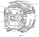
- FIG. 1 Lye container (1) shown is used in the washing unit of a coat-loadable washing machine, a so-called top loader.
- the tub container jacket (2) is provided with an opening (3) which corresponds to the opening in the shell of a drum, not shown in the drawings.
- the opening in the front deck is arranged (closed at the top loader, s. FIG. 4 ).
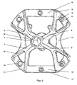
- the drum has in a known manner a shaft journal which is received by two spaced-apart bearings (not shown). These two bearings are arranged in a sleeve-shaped bearing seat (4) which is located in the center of a in FIG. 2 shown supporting contour (5) is located.
- the supporting contour (5) has at least one or more radially extending arms, wherein in an advantageous embodiment the supporting contour (5) has four arms (6, 7, 8, 9), two of which run diagonally in the installed state. In the end region, all four arms (6, 7, 8, 9) branches (10), whose ends are connected to each other by radially outwardly curved struts (11).
- the two upper arms (6, 9) and the two lower arms (7, 8) are each connected by straight struts (12). Between the two left arms (6, 7) and the two right arms (8, 9) inwardly curved struts (13) are arranged.
- the struts (11, 12, 13) of the closed circumference of the supporting contour (5) is formed, which is cut by two pairs of diagonally extending pairs of arms (6, 8 and 7, 9) and in the center of the bearing seat (4 ) wearing.
- the struts 11 and 12 and the two upper arms (6, 9) are provided with bearing lugs (14) or centering lugs (15) whose function is explained later.
- the entire support contour (5) is made as a one-piece molded part made of cast iron. In the area of the bore (16) which forms the bearing seat (4), a machining operation takes place after the casting in order to precisely define the fit for the bearings.
- the above-described supporting contour (5) is inserted into an injection mold (not shown).
- the bore (16) is placed on a mandrel (not shown), the centering lugs (15) are used for angular fixing and the bearing lugs (14) prevent tilting of the contour (5) in the mold.
- the mold is almost completely encapsulated with a glass fiber reinforced plastic, only the bearing and centering lugs and the bore (16) remain free.
- a one-piece tub is produced, which forms the shell (2) and the first end face of the bottom (17) of the tub (1), wherein the contour (5) completely in the material of the bottom (17 ) is embedded.
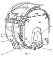
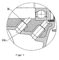
- FIG. 3 shows in a section the embedding of the contour (5).
- the inner surface of the bottom (17) is flat except for a bulge (18) in the region of the bearing seat (4).
- the vat is replaced by a in FIG. 4 represented front cap (19), which then forms the second end face, to a tub (1) completed.
- a in FIG. 4 represented front cap (19), which then forms the second end face, to a tub (1) completed.
- a tub (1) completed For mutual attachment of the two parts erdome (20) are provided. It has proved to be advantageous to provide for each attachment point domes (20) with two threaded holes (21, 22). As a result, even after damage to the thread (21) in a mandrel (20) - about after repeated loosening of the screws - a secure and tight connection of the tub and front cap by using the second thread (22) possible.
- balance weight On the front cap (19) is a horseshoe-shaped balance weight (23), advantageously made of cast iron, attached via further screw domes (24).
- the balance weight can be encapsulated similar to the supporting contour and so be embedded by the material of the front cap. This eliminates the separate attachment.
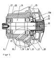
- FIG. 5 shows the bearing assembly of a washing unit for a washing machine in the side view in section.
- the washing unit has a substantially cylindrical tub (1) and a rotatably mounted therein, also cylindrical drum (31) for receiving the laundry (not shown).
- the tub (1) is made of alkali-resistant plastic and has in the center of its bottom (17) has an opening (16), behind which a bearing housing (4) is arranged. The latter is carried by a bearing cross, not shown.
- the connection of bearing cross and bearing housing (4) with the tub (1) is part of the manufacturing process described later.
- a shaft journal (30) connected to the drum (31) via a flange (32) is passed through the opening (16).
- the bearing for the drum consists of a front and a rear radial ball bearing (26, 27) which are fixed by press fitting in the receiving bore (16) of the bearing housing (4) and receive the shaft journal (30).
- the front bearing (26) is protected by a radial shaft sealing ring (28) which is inserted into the opening (16a) of the suds container bottom (17) located in front of the bearing housing (4).
- In the bearing housing (4) there are two continuous drainage holes (33, 34), of which one (33) in the region of the radial shaft seal (28) and the other (34) between the two bearings (27, 28) in the receiving bore (16 ) opens.
- the bearing housing (4) with the two drainage holes (33, 34) is provided.
- This tub consists of the jacket (2) and the bottom (17) of the tub (1).
- the receiving bore (16) on a mandrel (not shown) inserted.
- two cores (not shown) are driven, the ends of which protrude from the radial shaft sealing ring (28) opposite end.
- bearing housing (4), cores and bearing cross are molded with a polymeric mass of glass fiber reinforced plastic, only the receiving bore (16) remains free. In this way, the tub is made in one piece.
- the front and the rear core are pulled out with a slide from the respective outflow bore (33, 34) and there are two free flows in the plastic jacket (25) surrounding the bearing housing (4). 35, 36).
- this accumulated condensation water from the bore (16) in the outer region (29) of the bearing housing (4) are derived.
- the inner wall of the bore (33, 34) are also coated with plastic (37).
- the core has a smaller diameter than the bore (33, 34), wherein the thickness of the plastic coating from half the difference between the diameter of the bore (33, 34) in the bearing housing and the diameter of the core is determined or fixed.
- FIG. 7 a further advantageous embodiment of the bore (33, 34) is shown, in which the inner wall is coated only in a partial area with plastic (37 a).
- the bore (33, 34) in the bearing housing in a front region has a first diameter and in a rear region a second diameter, wherein the first diameter is greater than the second diameter.
- the core is inserted only in the first area of the bore (33, 34) and seals at the offset (38) to the rear of the bore.
- the core has a smaller diameter, as the bore (33, 34) in the first region, wherein the thickness of the plastic coating of half the difference between the first diameter of the bore (33, 34) results in the bearing housing and the diameter of the core.
Landscapes
- Engineering & Computer Science (AREA)
- Textile Engineering (AREA)
- General Engineering & Computer Science (AREA)
- Mechanical Engineering (AREA)
- Manufacturing & Machinery (AREA)
- Main Body Construction Of Washing Machines And Laundry Dryers (AREA)
- Injection Moulding Of Plastics Or The Like (AREA)
- Processing And Handling Of Plastics And Other Materials For Molding In General (AREA)
- Moulds For Moulding Plastics Or The Like (AREA)
Priority Applications (1)
| Application Number | Priority Date | Filing Date | Title |
|---|---|---|---|
| PL10007272T PL2241666T3 (pl) | 2003-10-29 | 2004-10-06 | Sposób wytwarzania agregatu piorącego z pojemnikiem na detergenty wykonanym z tworzywa sztucznego |
Applications Claiming Priority (3)
| Application Number | Priority Date | Filing Date | Title |
|---|---|---|---|
| DE10350793 | 2003-10-29 | ||
| DE10350794A DE10350794A1 (de) | 2003-10-29 | 2003-10-29 | Verfahren zur Herstellung eines Waschaggregats für eine Waschmaschine |
| EP04023746A EP1528136B1 (de) | 2003-10-29 | 2004-10-06 | Waschaggregat für eine Waschmaschine mit einem Laugenbehälter aus Kunststoff |
Related Parent Applications (1)
| Application Number | Title | Priority Date | Filing Date |
|---|---|---|---|
| EP04023746.3 Division | 2004-10-06 |
Publications (2)
| Publication Number | Publication Date |
|---|---|
| EP2241666A1 EP2241666A1 (de) | 2010-10-20 |
| EP2241666B1 true EP2241666B1 (de) | 2011-11-23 |
Family
ID=34424341
Family Applications (2)
| Application Number | Title | Priority Date | Filing Date |
|---|---|---|---|
| EP10007272A Expired - Lifetime EP2241666B1 (de) | 2003-10-29 | 2004-10-06 | Verfahren zur Herstellung eines Waschaggregats mit einem Laugenbehälter aus Kunststoff |
| EP04023746A Expired - Lifetime EP1528136B1 (de) | 2003-10-29 | 2004-10-06 | Waschaggregat für eine Waschmaschine mit einem Laugenbehälter aus Kunststoff |
Family Applications After (1)
| Application Number | Title | Priority Date | Filing Date |
|---|---|---|---|
| EP04023746A Expired - Lifetime EP1528136B1 (de) | 2003-10-29 | 2004-10-06 | Waschaggregat für eine Waschmaschine mit einem Laugenbehälter aus Kunststoff |
Country Status (5)
| Country | Link |
|---|---|
| EP (2) | EP2241666B1 (pl) |
| AT (2) | ATE493535T1 (pl) |
| DE (1) | DE502004012051D1 (pl) |
| ES (2) | ES2354424T3 (pl) |
| PL (2) | PL1528136T3 (pl) |
Families Citing this family (27)
| Publication number | Priority date | Publication date | Assignee | Title |
|---|---|---|---|---|
| DE102004047996A1 (de) * | 2004-10-01 | 2006-04-06 | BSH Bosch und Siemens Hausgeräte GmbH | Tragstern für eine Waschmaschine |
| DE102005018190B3 (de) * | 2005-04-19 | 2006-08-24 | Miele & Cie. Kg | Kunststofflaugenbehälter für eine Waschmaschine und Verfahren zur Herstellung eines Kunststofflaugenbehälters |
| DE102005019414B3 (de) * | 2005-04-25 | 2006-05-18 | Miele & Cie. Kg | Kunststofflaugenbehälter für eine Waschmaschine |
| DE102005045178B3 (de) * | 2005-09-21 | 2006-10-12 | Miele & Cie. Kg | Kunststofflaugenbehälter für eine Waschmaschine und Verfahren zur Herstellung eines Kunststofflaugenbehälters |
| DE102005046010B3 (de) * | 2005-09-26 | 2006-10-12 | Miele & Cie. Kg | Kunststofflaugenbehälter für eine Waschmaschine und Verfahren zur Herstellung eines Kuststofflaugenbehälters |
| DE102005054968B3 (de) * | 2005-11-16 | 2006-11-02 | Miele & Cie. Kg | Kunststofflaugenbehälter für eine Wäschebehandlungsmaschine und Wäschebehandlungsmaschine |
| DE102006036133B3 (de) * | 2006-08-01 | 2007-09-06 | Miele & Cie. Kg | Mantelbeschickbare Waschmaschine bzw. Toplader-Waschmaschine |
| EP2129823B1 (en) * | 2007-02-21 | 2011-10-19 | Meccanica Generale S.R.L. | Washing machine tank provided with external reinforcing cap on bottom wall |
| US8677789B2 (en) | 2007-09-20 | 2014-03-25 | Bsh Bosch Und Siemens Hausgerate Gmbh | Plastic suds tub for a washing machine or a washer/dryer |
| DE102007044882A1 (de) | 2007-09-20 | 2009-04-09 | BSH Bosch und Siemens Hausgeräte GmbH | Kunststoff-Laugenbehälter für eine Waschmaschine oder einen Waschtrockner |
| DE102007061526A1 (de) | 2007-12-20 | 2009-06-25 | BSH Bosch und Siemens Hausgeräte GmbH | Kunststoff-Laugenbehälter für eine Waschmaschine oder einen Waschtrockner und Verfahren zur Herstellung des Laugenbehälters |
| ITMC20080007A1 (it) * | 2008-01-16 | 2009-07-17 | Meccanica Generale Srl | Metodo per la realizzazione di un supporto portacuscinetti in lamiera stampata. |
| DE102008053250A1 (de) * | 2008-10-25 | 2010-04-29 | Aksys Gmbh | Vorrichtung zum Auffangen von Flüssigkeiten und Verfahren zur Herstellung einer derartigen Vorrichtung |
| IT1398582B1 (it) * | 2010-03-09 | 2013-03-01 | Skf Ab | Cannotto costampabile con vasche di lavatrici |
| IT1399001B1 (it) * | 2010-03-25 | 2013-03-28 | Skf Ab | Cannotto costampabile. |
| EP2659049B1 (en) * | 2010-12-29 | 2016-11-16 | Arçelik Anonim Sirketi | A washing machine comprising a plastic bearing sleeve |
| CN103255599B (zh) * | 2012-02-20 | 2015-07-15 | 苏州三星电子有限公司 | 滚筒洗衣机及其平衡结构 |
| ITTO20130745A1 (it) * | 2013-09-13 | 2015-03-14 | Skf Ab | Cannotto costampabile con vasche di lavatrici |
| DE102013113391B4 (de) | 2013-12-03 | 2020-03-26 | Miele & Cie. Kg | Laugenbehälter aus Kunststoff für Waschmaschinen und Waschtrockner und Verfahren zu dessen Herstellung |
| DE102015102932A1 (de) * | 2015-03-02 | 2016-09-08 | Miele & Cie. Kg | Laugenbehälter für eine Waschmaschine |
| DE102015103013A1 (de) | 2015-03-03 | 2016-09-08 | Miele & Cie. Kg | Laugenbehälter aus Kunststoff für Waschmaschinen und Waschtrockner |
| CN104963953A (zh) * | 2015-06-05 | 2015-10-07 | 惠而浦(中国)股份有限公司 | 一种滚筒洗衣机的轴承座 |
| CN104963167A (zh) * | 2015-06-05 | 2015-10-07 | 惠而浦(中国)股份有限公司 | 滚筒洗衣机外桶后端部组件 |
| CN107780139B (zh) * | 2016-08-29 | 2020-12-25 | 青岛海尔洗衣机有限公司 | 一种结构加强型洗衣机外桶及洗衣机 |
| CN107365096A (zh) * | 2017-08-15 | 2017-11-21 | 徐州蓝湖信息科技有限公司 | 一种保温混凝土聚苯乙烯骨料制备装置 |
| CN109402958B (zh) * | 2017-08-16 | 2022-05-27 | 青岛海尔滚筒洗衣机有限公司 | 一种洗衣机 |
| KR102557578B1 (ko) | 2018-08-23 | 2023-07-20 | 엘지전자 주식회사 | 세탁장치 |
Family Cites Families (12)
| Publication number | Priority date | Publication date | Assignee | Title |
|---|---|---|---|---|
| DE2719336A1 (de) | 1977-04-30 | 1978-11-09 | Miele & Cie | Wasch- und schleudermaschine |
| IT1136452B (it) | 1980-07-03 | 1986-08-27 | Zanussi A Spa Industrie | Vasca in materia plastica per macchine lavabiancheria |
| DE8622028U1 (de) * | 1986-08-16 | 1986-12-18 | Chemieschutz Gesellschaft für Säurebau mbH, 6140 Bensheim | Abstandshalter zum Zentrieren von im Spritzgußverfahren zu ummantelnden Kernen im Gießformhohlraum |
| IT1225857B (it) | 1988-12-21 | 1990-12-07 | Industre Zanussi S P A | Procedimento di fabbricazione di vasche in plastica per macchinelavabiancheria e vasca cosi' ottenuta |
| IT1246496B (it) * | 1989-12-22 | 1994-11-19 | Bosch Siemens Hausgeraete | Procedimento per produrre organi di trascinamento in materia artificiale per tamburi di macchine lavatrici e organo di trascinament con esso prodotto. |
| DE4011653A1 (de) * | 1990-04-11 | 1991-10-17 | Schaeffler Waelzlager Kg | Vorrichtung zum umspritzen oder umgiessen eines metallringes mit einem polymeren werkstoff |
| GB2272913A (en) | 1992-11-26 | 1994-06-01 | Caradon Rolinx | Tub for a top-loading washing machine |
| IT245289Y1 (it) * | 1998-01-20 | 2002-03-20 | Electrolux Zanussi Elettrodome | Vasca in plastica perfezionata per macchina lavabiancheriae simili |
| DE19911139A1 (de) * | 1999-03-12 | 2000-09-14 | Bsh Bosch Siemens Hausgeraete | Antriebsvorrichtung für eine von vorn beschickbare Waschmaschine |
| DE19960501A1 (de) * | 1999-12-15 | 2001-06-21 | Bsh Bosch Siemens Hausgeraete | Laugenbehälter für eine Waschmaschine |
| DE10040319C1 (de) | 2000-08-17 | 2001-09-27 | Whirlpool Co | Trommellagerung für eine Frontlader-Waschmaschine |
| DE10216517A1 (de) * | 2002-04-15 | 2003-09-11 | Ticona Gmbh | Laugenbottich für Waschmaschinen, Geschirrspülmaschinen oder dergleichen und Verfahren zu seiner Herstellung |
-
2004
- 2004-10-06 EP EP10007272A patent/EP2241666B1/de not_active Expired - Lifetime
- 2004-10-06 PL PL04023746T patent/PL1528136T3/pl unknown
- 2004-10-06 ES ES04023746T patent/ES2354424T3/es not_active Expired - Lifetime
- 2004-10-06 DE DE502004012051T patent/DE502004012051D1/de not_active Expired - Lifetime
- 2004-10-06 EP EP04023746A patent/EP1528136B1/de not_active Expired - Lifetime
- 2004-10-06 ES ES10007272T patent/ES2373781T3/es not_active Expired - Lifetime
- 2004-10-06 AT AT04023746T patent/ATE493535T1/de active
- 2004-10-06 AT AT10007272T patent/ATE534764T1/de active
- 2004-10-06 PL PL10007272T patent/PL2241666T3/pl unknown
Also Published As
| Publication number | Publication date |
|---|---|
| EP1528136A2 (de) | 2005-05-04 |
| PL1528136T3 (pl) | 2011-04-29 |
| EP2241666A1 (de) | 2010-10-20 |
| ATE534764T1 (de) | 2011-12-15 |
| PL2241666T3 (pl) | 2012-03-30 |
| ATE493535T1 (de) | 2011-01-15 |
| ES2354424T3 (es) | 2011-03-14 |
| EP1528136B1 (de) | 2010-12-29 |
| ES2373781T3 (es) | 2012-02-08 |
| DE502004012051D1 (de) | 2011-02-10 |
| EP1528136A3 (de) | 2008-04-23 |
Similar Documents
| Publication | Publication Date | Title |
|---|---|---|
| EP2241666B1 (de) | Verfahren zur Herstellung eines Waschaggregats mit einem Laugenbehälter aus Kunststoff | |
| EP2040354B2 (de) | Spaltrohr eines Antriebsmotors für ein Pumpenaggregat | |
| EP2201167B1 (de) | Kunststoff-laugenbehälter für eine waschmaschine oder einen waschtrockner | |
| EP1240376B1 (de) | Laugenbehälter für eine waschmaschine | |
| DE3650511T2 (de) | Verfahren zur Herstellung eines Waschmaschinenbehälters und mittels eines solchen Verfahrens hergestellter Behälter | |
| EP2203583B1 (de) | Kunststoff-laugenbehälter für eine waschmaschine oder einen waschtrockner | |
| DE69634136T2 (de) | Beschichtete rolle und verfahren zu ihrer herstellung | |
| DE3523518A1 (de) | Ringfoermiger schaufelkoerper mit einem integralen schaufelring und verfahren zur herstellung desselben | |
| EP2040352B1 (de) | Spaltrohr sowie Verfahren zum Herstellen eines Spaltrohres | |
| EP1767686B1 (de) | Kunststofflaugenbehälter für eine Waschmaschine und Verfahren zur Herstellung eines Kunststofflaugenbehälters | |
| EP1715096B1 (de) | Kunststofflaugenbehälter für eine Waschmaschine und Verfahren zur Herstellung eines Kunststofflaugenbehälters | |
| WO2009080421A1 (de) | Kunststoff-laugenbehälter für eine waschmaschine oder einen waschtrockner und verfahren zur herstellung des laugenbehälters | |
| EP3521631B1 (de) | Pumpenlaufrad, verfahren zur herstellung eines pumpenlaufrads und pumpe mit dem pumpenlaufrad | |
| DE10350794A1 (de) | Verfahren zur Herstellung eines Waschaggregats für eine Waschmaschine | |
| EP3757272B1 (de) | Manschette für ein wäschebehandlungsgerät, wäschebehandlungsgerät und verfahren zum einstellen eines spaltmasses | |
| DE112006003872B4 (de) | Wanne für eine Waschmaschine | |
| DE10345848A1 (de) | Laugenbehälter für Waschmaschinen oder Trockner aus Kunststoff | |
| DE112006003878B4 (de) | Waschmaschine | |
| EP1788137B1 (de) | Kunststofflaugenbehälter für eine Wäschebehandlungsmaschine und Wäschebehandlungsmaschine | |
| EP2512769B1 (de) | Kunststoff-laugenbehälter, und verfahren zur herstellung des kunststoff-laugenbehälters | |
| DE10227036C1 (de) | Waschaggregat für eine Waschmaschine | |
| EP3530793B1 (de) | Waschmaschine mit einer dichtanordnung für eine lageranordnung eines laugenbehälters der waschmaschine | |
| DE102017206089A1 (de) | Nassläufer-Pumpe und Haushaltsgerät | |
| DE19911491B4 (de) | Injektionseinheit | |
| CN109967712A (zh) | 用于不同材料的离心铸造装置 |
Legal Events
| Date | Code | Title | Description |
|---|---|---|---|
| PUAI | Public reference made under article 153(3) epc to a published international application that has entered the european phase |
Free format text: ORIGINAL CODE: 0009012 |
|
| AC | Divisional application: reference to earlier application |
Ref document number: 1528136 Country of ref document: EP Kind code of ref document: P |
|
| AK | Designated contracting states |
Kind code of ref document: A1 Designated state(s): AT BE BG CH CY CZ DE DK EE ES FI FR GB GR HU IE IT LI LU MC NL PL PT RO SE SI SK TR |
|
| 17P | Request for examination filed |
Effective date: 20100923 |
|
| GRAP | Despatch of communication of intention to grant a patent |
Free format text: ORIGINAL CODE: EPIDOSNIGR1 |
|
| 17Q | First examination report despatched |
Effective date: 20110429 |
|
| RIC1 | Information provided on ipc code assigned before grant |
Ipc: B29C 45/14 20060101ALI20110517BHEP Ipc: D06F 23/02 20060101ALI20110517BHEP Ipc: D06F 37/26 20060101AFI20110517BHEP |
|
| GRAS | Grant fee paid |
Free format text: ORIGINAL CODE: EPIDOSNIGR3 |
|
| GRAA | (expected) grant |
Free format text: ORIGINAL CODE: 0009210 |
|
| AC | Divisional application: reference to earlier application |
Ref document number: 1528136 Country of ref document: EP Kind code of ref document: P |
|
| AK | Designated contracting states |
Kind code of ref document: B1 Designated state(s): AT BE BG CH CY CZ DE DK EE ES FI FR GB GR HU IE IT LI LU MC NL PL PT RO SE SI SK TR |
|
| REG | Reference to a national code |
Ref country code: GB Ref legal event code: FG4D Free format text: NOT ENGLISH |
|
| REG | Reference to a national code |
Ref country code: CH Ref legal event code: EP |
|
| REG | Reference to a national code |
Ref country code: IE Ref legal event code: FG4D Free format text: LANGUAGE OF EP DOCUMENT: GERMAN |
|
| REG | Reference to a national code |
Ref country code: GB Ref legal event code: 746 Effective date: 20111219 |
|
| REG | Reference to a national code |
Ref country code: ES Ref legal event code: GC2A Effective date: 20120116 Ref country code: DE Ref legal event code: R096 Ref document number: 502004013093 Country of ref document: DE Effective date: 20120126 |
|
| REG | Reference to a national code |
Ref country code: DE Ref legal event code: R084 Ref document number: 502004013093 Country of ref document: DE Effective date: 20111208 |
|
| REG | Reference to a national code |
Ref country code: ES Ref legal event code: FG2A Ref document number: 2373781 Country of ref document: ES Kind code of ref document: T3 Effective date: 20120208 |
|
| REG | Reference to a national code |
Ref country code: NL Ref legal event code: VDEP Effective date: 20111123 |
|
| REG | Reference to a national code |
Ref country code: PL Ref legal event code: T3 Ref country code: PL Ref legal event code: LICE Effective date: 20120112 |
|
| PG25 | Lapsed in a contracting state [announced via postgrant information from national office to epo] |
Ref country code: SI Free format text: LAPSE BECAUSE OF FAILURE TO SUBMIT A TRANSLATION OF THE DESCRIPTION OR TO PAY THE FEE WITHIN THE PRESCRIBED TIME-LIMIT Effective date: 20111123 Ref country code: SE Free format text: LAPSE BECAUSE OF FAILURE TO SUBMIT A TRANSLATION OF THE DESCRIPTION OR TO PAY THE FEE WITHIN THE PRESCRIBED TIME-LIMIT Effective date: 20111123 Ref country code: GR Free format text: LAPSE BECAUSE OF FAILURE TO SUBMIT A TRANSLATION OF THE DESCRIPTION OR TO PAY THE FEE WITHIN THE PRESCRIBED TIME-LIMIT Effective date: 20120224 Ref country code: NL Free format text: LAPSE BECAUSE OF FAILURE TO SUBMIT A TRANSLATION OF THE DESCRIPTION OR TO PAY THE FEE WITHIN THE PRESCRIBED TIME-LIMIT Effective date: 20111123 Ref country code: PT Free format text: LAPSE BECAUSE OF FAILURE TO SUBMIT A TRANSLATION OF THE DESCRIPTION OR TO PAY THE FEE WITHIN THE PRESCRIBED TIME-LIMIT Effective date: 20120323 |
|
| REG | Reference to a national code |
Ref country code: IE Ref legal event code: FD4D |
|
| PG25 | Lapsed in a contracting state [announced via postgrant information from national office to epo] |
Ref country code: CY Free format text: LAPSE BECAUSE OF FAILURE TO SUBMIT A TRANSLATION OF THE DESCRIPTION OR TO PAY THE FEE WITHIN THE PRESCRIBED TIME-LIMIT Effective date: 20111123 |
|
| PG25 | Lapsed in a contracting state [announced via postgrant information from national office to epo] |
Ref country code: BG Free format text: LAPSE BECAUSE OF FAILURE TO SUBMIT A TRANSLATION OF THE DESCRIPTION OR TO PAY THE FEE WITHIN THE PRESCRIBED TIME-LIMIT Effective date: 20120223 Ref country code: IE Free format text: LAPSE BECAUSE OF FAILURE TO SUBMIT A TRANSLATION OF THE DESCRIPTION OR TO PAY THE FEE WITHIN THE PRESCRIBED TIME-LIMIT Effective date: 20111123 Ref country code: DK Free format text: LAPSE BECAUSE OF FAILURE TO SUBMIT A TRANSLATION OF THE DESCRIPTION OR TO PAY THE FEE WITHIN THE PRESCRIBED TIME-LIMIT Effective date: 20111123 Ref country code: SK Free format text: LAPSE BECAUSE OF FAILURE TO SUBMIT A TRANSLATION OF THE DESCRIPTION OR TO PAY THE FEE WITHIN THE PRESCRIBED TIME-LIMIT Effective date: 20111123 Ref country code: EE Free format text: LAPSE BECAUSE OF FAILURE TO SUBMIT A TRANSLATION OF THE DESCRIPTION OR TO PAY THE FEE WITHIN THE PRESCRIBED TIME-LIMIT Effective date: 20111123 Ref country code: CZ Free format text: LAPSE BECAUSE OF FAILURE TO SUBMIT A TRANSLATION OF THE DESCRIPTION OR TO PAY THE FEE WITHIN THE PRESCRIBED TIME-LIMIT Effective date: 20111123 |
|
| PG25 | Lapsed in a contracting state [announced via postgrant information from national office to epo] |
Ref country code: RO Free format text: LAPSE BECAUSE OF FAILURE TO SUBMIT A TRANSLATION OF THE DESCRIPTION OR TO PAY THE FEE WITHIN THE PRESCRIBED TIME-LIMIT Effective date: 20111123 |
|
| PLBE | No opposition filed within time limit |
Free format text: ORIGINAL CODE: 0009261 |
|
| STAA | Information on the status of an ep patent application or granted ep patent |
Free format text: STATUS: NO OPPOSITION FILED WITHIN TIME LIMIT |
|
| 26N | No opposition filed |
Effective date: 20120824 |
|
| REG | Reference to a national code |
Ref country code: DE Ref legal event code: R097 Ref document number: 502004013093 Country of ref document: DE Effective date: 20120824 |
|
| BERE | Be: lapsed |
Owner name: MIELE & CIE. K.G. Effective date: 20121031 |
|
| PG25 | Lapsed in a contracting state [announced via postgrant information from national office to epo] |
Ref country code: MC Free format text: LAPSE BECAUSE OF NON-PAYMENT OF DUE FEES Effective date: 20121031 |
|
| REG | Reference to a national code |
Ref country code: CH Ref legal event code: PL |
|
| PG25 | Lapsed in a contracting state [announced via postgrant information from national office to epo] |
Ref country code: FI Free format text: LAPSE BECAUSE OF FAILURE TO SUBMIT A TRANSLATION OF THE DESCRIPTION OR TO PAY THE FEE WITHIN THE PRESCRIBED TIME-LIMIT Effective date: 20111123 |
|
| PG25 | Lapsed in a contracting state [announced via postgrant information from national office to epo] |
Ref country code: CH Free format text: LAPSE BECAUSE OF NON-PAYMENT OF DUE FEES Effective date: 20121031 Ref country code: LI Free format text: LAPSE BECAUSE OF NON-PAYMENT OF DUE FEES Effective date: 20121031 Ref country code: BE Free format text: LAPSE BECAUSE OF NON-PAYMENT OF DUE FEES Effective date: 20121031 |
|
| REG | Reference to a national code |
Ref country code: AT Ref legal event code: MM01 Ref document number: 534764 Country of ref document: AT Kind code of ref document: T Effective date: 20121031 |
|
| PG25 | Lapsed in a contracting state [announced via postgrant information from national office to epo] |
Ref country code: AT Free format text: LAPSE BECAUSE OF NON-PAYMENT OF DUE FEES Effective date: 20121031 |
|
| PG25 | Lapsed in a contracting state [announced via postgrant information from national office to epo] |
Ref country code: LU Free format text: LAPSE BECAUSE OF NON-PAYMENT OF DUE FEES Effective date: 20121006 |
|
| PG25 | Lapsed in a contracting state [announced via postgrant information from national office to epo] |
Ref country code: HU Free format text: LAPSE BECAUSE OF FAILURE TO SUBMIT A TRANSLATION OF THE DESCRIPTION OR TO PAY THE FEE WITHIN THE PRESCRIBED TIME-LIMIT Effective date: 20041006 |
|
| REG | Reference to a national code |
Ref country code: FR Ref legal event code: PLFP Year of fee payment: 12 |
|
| REG | Reference to a national code |
Ref country code: FR Ref legal event code: PLFP Year of fee payment: 13 |
|
| REG | Reference to a national code |
Ref country code: FR Ref legal event code: PLFP Year of fee payment: 14 |
|
| REG | Reference to a national code |
Ref country code: FR Ref legal event code: PLFP Year of fee payment: 15 |
|
| PGFP | Annual fee paid to national office [announced via postgrant information from national office to epo] |
Ref country code: DE Payment date: 20191031 Year of fee payment: 16 |
|
| PGFP | Annual fee paid to national office [announced via postgrant information from national office to epo] |
Ref country code: FR Payment date: 20191025 Year of fee payment: 16 Ref country code: IT Payment date: 20191024 Year of fee payment: 16 Ref country code: ES Payment date: 20191125 Year of fee payment: 16 |
|
| PGFP | Annual fee paid to national office [announced via postgrant information from national office to epo] |
Ref country code: TR Payment date: 20191003 Year of fee payment: 16 |
|
| PGFP | Annual fee paid to national office [announced via postgrant information from national office to epo] |
Ref country code: GB Payment date: 20191029 Year of fee payment: 16 |
|
| PGFP | Annual fee paid to national office [announced via postgrant information from national office to epo] |
Ref country code: PL Payment date: 20200810 Year of fee payment: 17 |
|
| REG | Reference to a national code |
Ref country code: DE Ref legal event code: R119 Ref document number: 502004013093 Country of ref document: DE |
|
| GBPC | Gb: european patent ceased through non-payment of renewal fee |
Effective date: 20201006 |
|
| PG25 | Lapsed in a contracting state [announced via postgrant information from national office to epo] |
Ref country code: DE Free format text: LAPSE BECAUSE OF NON-PAYMENT OF DUE FEES Effective date: 20210501 Ref country code: FR Free format text: LAPSE BECAUSE OF NON-PAYMENT OF DUE FEES Effective date: 20201031 |
|
| PG25 | Lapsed in a contracting state [announced via postgrant information from national office to epo] |
Ref country code: GB Free format text: LAPSE BECAUSE OF NON-PAYMENT OF DUE FEES Effective date: 20201006 |
|
| PG25 | Lapsed in a contracting state [announced via postgrant information from national office to epo] |
Ref country code: IT Free format text: LAPSE BECAUSE OF NON-PAYMENT OF DUE FEES Effective date: 20201006 |
|
| REG | Reference to a national code |
Ref country code: ES Ref legal event code: FD2A Effective date: 20220119 |
|
| PG25 | Lapsed in a contracting state [announced via postgrant information from national office to epo] |
Ref country code: ES Free format text: LAPSE BECAUSE OF NON-PAYMENT OF DUE FEES Effective date: 20201007 |
|
| PG25 | Lapsed in a contracting state [announced via postgrant information from national office to epo] |
Ref country code: TR Free format text: LAPSE BECAUSE OF NON-PAYMENT OF DUE FEES Effective date: 20201006 |
|
| PG25 | Lapsed in a contracting state [announced via postgrant information from national office to epo] |
Ref country code: PL Free format text: LAPSE BECAUSE OF NON-PAYMENT OF DUE FEES Effective date: 20211006 |