EP2240972B1 - Schutzmantel - Google Patents
Schutzmantel Download PDFInfo
- Publication number
- EP2240972B1 EP2240972B1 EP20080862328 EP08862328A EP2240972B1 EP 2240972 B1 EP2240972 B1 EP 2240972B1 EP 20080862328 EP20080862328 EP 20080862328 EP 08862328 A EP08862328 A EP 08862328A EP 2240972 B1 EP2240972 B1 EP 2240972B1
- Authority
- EP
- European Patent Office
- Prior art keywords
- protective jacket
- wall
- heat insulating
- insulating material
- sheet
- Prior art date
- Legal status (The legal status is an assumption and is not a legal conclusion. Google has not performed a legal analysis and makes no representation as to the accuracy of the status listed.)
- Not-in-force
Links
- 230000001681 protective effect Effects 0.000 title claims abstract description 336
- 239000011324 bead Substances 0.000 claims abstract description 329
- 239000011810 insulating material Substances 0.000 claims description 317
- 239000006260 foam Substances 0.000 claims description 224
- -1 polypropylene Polymers 0.000 claims description 110
- 239000004743 Polypropylene Substances 0.000 claims description 106
- 229920001155 polypropylene Polymers 0.000 claims description 106
- 238000003466 welding Methods 0.000 claims description 23
- 239000000463 material Substances 0.000 claims description 20
- 238000004519 manufacturing process Methods 0.000 claims description 14
- 239000010410 layer Substances 0.000 description 115
- 238000009413 insulation Methods 0.000 description 33
- 238000005520 cutting process Methods 0.000 description 28
- 238000004026 adhesive bonding Methods 0.000 description 19
- 238000003825 pressing Methods 0.000 description 16
- 230000015572 biosynthetic process Effects 0.000 description 15
- 238000000034 method Methods 0.000 description 13
- 230000006835 compression Effects 0.000 description 11
- 238000007906 compression Methods 0.000 description 11
- 239000004698 Polyethylene Substances 0.000 description 4
- 239000011888 foil Substances 0.000 description 4
- 238000003475 lamination Methods 0.000 description 4
- 229920000573 polyethylene Polymers 0.000 description 4
- 229920000098 polyolefin Polymers 0.000 description 4
- 229920001577 copolymer Polymers 0.000 description 3
- 229920001971 elastomer Polymers 0.000 description 2
- 239000004744 fabric Substances 0.000 description 2
- 238000005304 joining Methods 0.000 description 2
- VGGSQFUCUMXWEO-UHFFFAOYSA-N Ethene Chemical compound C=C VGGSQFUCUMXWEO-UHFFFAOYSA-N 0.000 description 1
- 239000005977 Ethylene Substances 0.000 description 1
- 239000004793 Polystyrene Substances 0.000 description 1
- 230000004308 accommodation Effects 0.000 description 1
- NIXOWILDQLNWCW-UHFFFAOYSA-N acrylic acid group Chemical group C(C=C)(=O)O NIXOWILDQLNWCW-UHFFFAOYSA-N 0.000 description 1
- 230000000694 effects Effects 0.000 description 1
- 239000000806 elastomer Substances 0.000 description 1
- 238000001125 extrusion Methods 0.000 description 1
- 238000010030 laminating Methods 0.000 description 1
- 239000002861 polymer material Substances 0.000 description 1
- 239000013047 polymeric layer Substances 0.000 description 1
- 229920002223 polystyrene Polymers 0.000 description 1
- QQONPFPTGQHPMA-UHFFFAOYSA-N propylene Natural products CC=C QQONPFPTGQHPMA-UHFFFAOYSA-N 0.000 description 1
- 125000004805 propylene group Chemical group [H]C([H])([H])C([H])([*:1])C([H])([H])[*:2] 0.000 description 1
- 229920001169 thermoplastic Polymers 0.000 description 1
- 229920002725 thermoplastic elastomer Polymers 0.000 description 1
- 229920001187 thermosetting polymer Polymers 0.000 description 1
- 239000004416 thermosoftening plastic Substances 0.000 description 1
Images


Classifications
-
- H—ELECTRICITY
- H01—ELECTRIC ELEMENTS
- H01M—PROCESSES OR MEANS, e.g. BATTERIES, FOR THE DIRECT CONVERSION OF CHEMICAL ENERGY INTO ELECTRICAL ENERGY
- H01M10/00—Secondary cells; Manufacture thereof
- H01M10/60—Heating or cooling; Temperature control
- H01M10/62—Heating or cooling; Temperature control specially adapted for specific applications
- H01M10/625—Vehicles
-
- H—ELECTRICITY
- H01—ELECTRIC ELEMENTS
- H01M—PROCESSES OR MEANS, e.g. BATTERIES, FOR THE DIRECT CONVERSION OF CHEMICAL ENERGY INTO ELECTRICAL ENERGY
- H01M10/00—Secondary cells; Manufacture thereof
- H01M10/60—Heating or cooling; Temperature control
- H01M10/61—Types of temperature control
- H01M10/617—Types of temperature control for achieving uniformity or desired distribution of temperature
-
- H—ELECTRICITY
- H01—ELECTRIC ELEMENTS
- H01M—PROCESSES OR MEANS, e.g. BATTERIES, FOR THE DIRECT CONVERSION OF CHEMICAL ENERGY INTO ELECTRICAL ENERGY
- H01M10/00—Secondary cells; Manufacture thereof
- H01M10/60—Heating or cooling; Temperature control
- H01M10/65—Means for temperature control structurally associated with the cells
- H01M10/658—Means for temperature control structurally associated with the cells by thermal insulation or shielding
-
- H—ELECTRICITY
- H01—ELECTRIC ELEMENTS
- H01M—PROCESSES OR MEANS, e.g. BATTERIES, FOR THE DIRECT CONVERSION OF CHEMICAL ENERGY INTO ELECTRICAL ENERGY
- H01M50/00—Constructional details or processes of manufacture of the non-active parts of electrochemical cells other than fuel cells, e.g. hybrid cells
- H01M50/10—Primary casings; Jackets or wrappings
- H01M50/116—Primary casings; Jackets or wrappings characterised by the material
- H01M50/124—Primary casings; Jackets or wrappings characterised by the material having a layered structure
-
- H—ELECTRICITY
- H01—ELECTRIC ELEMENTS
- H01M—PROCESSES OR MEANS, e.g. BATTERIES, FOR THE DIRECT CONVERSION OF CHEMICAL ENERGY INTO ELECTRICAL ENERGY
- H01M50/00—Constructional details or processes of manufacture of the non-active parts of electrochemical cells other than fuel cells, e.g. hybrid cells
- H01M50/20—Mountings; Secondary casings or frames; Racks, modules or packs; Suspension devices; Shock absorbers; Transport or carrying devices; Holders
- H01M50/233—Mountings; Secondary casings or frames; Racks, modules or packs; Suspension devices; Shock absorbers; Transport or carrying devices; Holders characterised by physical properties of casings or racks, e.g. dimensions
- H01M50/24—Mountings; Secondary casings or frames; Racks, modules or packs; Suspension devices; Shock absorbers; Transport or carrying devices; Holders characterised by physical properties of casings or racks, e.g. dimensions adapted for protecting batteries from their environment, e.g. from corrosion
-
- H—ELECTRICITY
- H01—ELECTRIC ELEMENTS
- H01M—PROCESSES OR MEANS, e.g. BATTERIES, FOR THE DIRECT CONVERSION OF CHEMICAL ENERGY INTO ELECTRICAL ENERGY
- H01M50/00—Constructional details or processes of manufacture of the non-active parts of electrochemical cells other than fuel cells, e.g. hybrid cells
- H01M50/50—Current conducting connections for cells or batteries
- H01M50/572—Means for preventing undesired use or discharge
- H01M50/598—Guarantee labels
-
- Y—GENERAL TAGGING OF NEW TECHNOLOGICAL DEVELOPMENTS; GENERAL TAGGING OF CROSS-SECTIONAL TECHNOLOGIES SPANNING OVER SEVERAL SECTIONS OF THE IPC; TECHNICAL SUBJECTS COVERED BY FORMER USPC CROSS-REFERENCE ART COLLECTIONS [XRACs] AND DIGESTS
- Y02—TECHNOLOGIES OR APPLICATIONS FOR MITIGATION OR ADAPTATION AGAINST CLIMATE CHANGE
- Y02E—REDUCTION OF GREENHOUSE GAS [GHG] EMISSIONS, RELATED TO ENERGY GENERATION, TRANSMISSION OR DISTRIBUTION
- Y02E60/00—Enabling technologies; Technologies with a potential or indirect contribution to GHG emissions mitigation
- Y02E60/10—Energy storage using batteries
Definitions
- the present invention relates to a protective jacket, which could be used to protect batteries and especially car batteries from excessive, repeated and/or unwanted temperature variations.
- the French patent application FR 2691291 describes for example a protective box comprising a lid, which may be fixed to it using a system on pins and holes to get a closed protective box.
- the closed protective box made for example of polystyrene thus protects a battery located inside the box from excessive, repeated and/or unwanted temperature variations.
- the international patent application WO 01/61769 discloses the use of a protective box comprising two parts, which may be welded together to get a closed protective box.
- the international patent application WO 04/064082 discloses the use of a protective box comprising at least a lid, a bottom element and a sidewall, which may be fixed for example by gluing or by using hooks and loops to get a protective box.
- the patent application JP 09120812 discloses the use of a protective box comprising an exterior case equipped with a lid and an acrylic foam which completely surrounds a battery located inside the exterior case.
- All these protective devices may achieve to get a better protection of a battery against excessive, repeated and/or unwanted temperature variations compared to batteries, which are used unprotected. This may be important because excessive, repeated and/or unwanted temperature variations may have negative effects on the ability of a battery to function and/or on its performance and/or on the battery's lifetime. This may be especially important as far as car batteries are concerned, because users want their cars and their car batteries to be highly reliable and providing high performance.
- the placement of the protective device may also be an important issue.
- a quick and/or easy placement of the protective device may be often highly desired to facilitate the implementation of the placement during industrial manufacturing and/or handling processes.
- To facilitate the use of a protective device it should thus be very quick and/or easy to place, while providing a good protection of a battery against excessive, repeated and/or unwanted temperature variations.
- the protective devices proposed in the art lag to provide a good protection of a battery against excessive, repeated and/or unwanted temperature variations, while also allowing an easy and/or quick placement.
- the object of the present invention is therefore to provide a protective jacket allowing a good protection of a battery against excessive, repeated and/or unwanted temperature variations, while also allowing a quick and/or easy placement of the protective jacket on the battery.
- this objective is achieved by a protective jacket having the features of the independent Claim 1.
- Advantageous refinements of the protective jacket are set forth in the subordinate Claims 2 through 17.
- the objective of the present invention is also achieved by a method to produce a protective jacket according to Claim 18.
- Advantageous embodiments of the method are likewise set forth in the subordinate Claims 19 through 20.
- the advantage of the protective jacket according to the present invention and of the appertaining method to produce a protective jacket according to the present invention lies in the effective and reliable protection of a battery against excessive, repeated and/or unwanted temperature variations, while also allowing a quick and/or easy placement of the protective jacket.
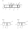
- a battery may be protected against excessive, repeated and/or unwanted temperature variations, by a protective jacket comprising at least four wall-elements linked one to another, each by at least two edges, whereby each of these wall-elements comprises at least one protruding bead arranged in a way, so that each protruding bead may be directed towards the inside of the protective jacket.
- a protective jacket comprising at least four wall-elements linked one to another, each by at least two edges, whereby each of these wall-elements comprises at least one protruding bead arranged in a way, so that each protruding bead may be directed towards the inside of the protective jacket.
- Directed towards the inside of the protective jacket may thereby mean that the protruding bead(s) may face an object to be protected, especially a battery or car battery, on which the protective jacket may be placed.
- a wall-element my thereby for example be a polygonal and preferably square like or even more preferred rectangular part of a plate and/or sheet of a heat insulating material used for the protective jacket.
- Each wall-element and/or each plate and/or sheet of a heat insulating material may have a certain thickness and dimensions, which may be slightly bigger than the dimensions of one side of an object to be protected and especially of a battery or car battery.
- Each wall-element may have different dimensions or the same dimensions depending on the design of the object to be protected and especially on design of the battery or car battery.
- the thickness of a plate and/or sheet of a heat insulating material used for the protective jacket and thus the thickness of a wall-element may be comprised for example between 1 mm and 40 mm, preferably between 1,5 mm and 30 mm, further preferred between 2 mm and 20 mm, further preferred between 2,5 mm and 10 mm, further preferred 3 and 6 mm. With an increasing thickness the protection of a battery against excessive, repeated and/or unwanted temperature variations becomes better.
- an increasing thickness may also allow to accommodate some production tolerances concerning the dimensions of an object to be protected, especially a battery or car battery, as well as concerning the dimensions of the protective jacket, although allowing a good fitting of the protective jacket on an object to be protected, especially a battery or car battery. This may allow a quick and/or easy placement of the protective jacket.
- the wall-elements may each have the same or different thicknesses. Moreover, at least one part of at least one wall-element may have a different thickness than at least one other part of this wall-element. This allows obtaining a good fitting of the protective jacket to an object to be protected, especially a battery or car battery.
- Dimensions which may be slightly bigger for the wall-element(s) than the dimensions of one side of an object to be protected and especially of a battery or car battery, may mean that the dimensions of the wall-element(s) are chosen to allow an open box without bottom part nor lid formed by the four wall-elements linked one to another, each by at least two edges, to be placed by sliding on an object to be protected, especially a battery or car battery, so that the protective jacket exactly fits the object to be protected and especially the battery or car battery and keeps at least partially in contact with the object to be protected, especially the battery or car battery.
- That the protective jacket keeps at least partially in contact with an object to be protected, especially a battery or car battery, may mean there may be a contact between at least one part of the protective jacket and specially between at least one of the protruding beads of the protective jacket and at least one part of an object to be protected and especially at least one part of a battery or car battery.
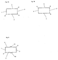
- the wall-elements of the protective jacket according to the present invention are linked one to another, each by at least two edges. This may be realized for example by using one or preferably two or even three or four plate(s) and/or sheet(s) of a heat insulating material used for assembling the protective jacket comprising each at least one wall-element.
- the plate(s) and/or sheet(s) of a heat insulating material used for the protective jacket may comprise one or more than one wall-element.
- one and the same plate and/or sheet comprises more than one wall-element especially two, three or four wall-elements
- At least two different wall-elements may however then be defined using at least one plate and/or sheet of a heat insulating material used for the protective jacket by folding this/these plate(s) and/or sheet(s) of a heat insulating material used for the protective jacket in an appropriate way, so that at least two polygonal parts of this/these plate(s) and/or sheet(s) of a heat insulating material used for the protective jacket, with dimensions that may be slightly bigger than the dimensions of one side of an object to be protected, especially of a battery or car battery may be defined.
- the protective jacket according the present invention is provided fully assembled, so that the at least four wall-elements are already linked one to another, each by at least two edges. It may therefore become possible to place the protective very quickly and/or easily on and/or around the object to be protected, especially the battery or car battery, preferably simply by sliding it on the object to be protected, especially the battery or car battery.
- no parts of the protective jacket have to be assembled, fixed together or to something else, glued together or to something else, welded together or with something else during and/or after the placement of the protective jacket, so that preferably no assembling, fixing, gluing or welding step or the like may therefore be required during and/or after the placement of the protective jacket.
- the placement of the protective jacket is thereby further facilitated.
- the wall-elements may all be part of the same plate and/or sheet of an heat insulating material used for the protective jacket, each wall-element being defined by folding the plate and/or sheet of a heat insulating material used for the protective jacket in an appropriate way, so that at least four polygonal parts of this plate and/or sheet of a heat insulating material used for the protective jacket, with dimensions that may be slightly bigger, than the dimensions of one side of an object to be protected and especially of a battery or car battery may be defined.
- one edge of this plate and/or sheet of an heat insulating material used for the protective jacket may be linked to another edge this plate and/or sheet of a heat insulating material used for the protective jacket to get a four walled box without lid nor bottom part, so that all wall-elements are linked one to another, each by at least two edges.
- This may mean that in this case at least two wall- elements may be linked together for example by gluing or welding or by any other suitable mean or technique, as two edges of the same plate and/or sheet of a heat insulating material used for the protective jacket may be linked together.
- the link between the two edges of this plate and/or sheet of a heat insulating material may thereby be provided for example by gluing and/or by welding or by any other suitable means or technique.
- the protective jacket may comprise at least two plates and/or sheets of a heat insulating material, which may each comprise at least one and preferably at least two wall-element(s).
- Two wall-elements may be defined by folding each plate and/or sheet of a heat insulating material, so that at least two polygonal parts of a plate and/or sheet of a heat insulating material, with dimensions that may be slightly bigger than the dimensions of one side of an object to be protected and especially of a battery or car battery may be defined.
- the different plates and/or sheets of a heat insulating material may be linked together preferably each by at least two of their edges to form four walled box without lid nor bottom part, so that all wall-elements are linked one to another, each by at least two edges.
- at least two plates and/or sheets of a heat insulating material used for the protective jacket may be linked together for example by gluing or welding or by any other suitable mean or technique, as two edges of at least one plate and/or sheet of a heat insulating material used for the protective jacket may be linked to at least two other edges of at least another plate and/or sheet of a heat insulating material used for the protective jacket.
- the link between the edges of these wall-elements and/or plates and/or sheets of a heat insulating material may thereby also be provided for example by gluing and/or by welding or by any other suitable mean or technique.
- Suitable means or techniques to provide a link between at least one edge of at least one wall-element and/or of at least one plate and/or sheet of a heat insulating material with at least another edge of at least another wall-element and/or of at least another or even of the same plate and/or sheet of a heat insulating material may for example be the lamination by applying heat and/or pressure of at least two wall-elements and/or at least one plate and/or sheet of a heat insulating material with a linking layer, which may be for example a polymeric layer especially a polymeric sheet, a woven or specially preferred a non woven layer specially for example a felt layer, so that all the wall-elements and/or all the plates and/or sheets of a heat insulating material laminated with the same linking layer are linked one to another by this linking layer.
- a linking layer which may be for example a polymeric layer especially a polymeric sheet, a woven or specially preferred a non woven layer specially for example a felt layer
- each wall-element may correspond to an individual plate and/or sheet of a heat insulating material.
- each wall-element and/or each plate and/or sheet of a heat insulating material may be linked to at least two other wall-elements and/or at least two other plates and/or sheets of a heat insulating material to form a four walled box without lid nor bottom part, so that all wall-elements are linked one to another, each by at least two edges.
- each wall-element corresponding to an individual plate and/or sheet of a heat insulating material may thus be linked to the other wall-elements and/or the other plate(s) and/or sheet(s) of a heat insulating material by at least two edges.
- the linking may thereby also be provided for example by gluing and/or by welding or by any other suitable mean or technique.
- wall-element(s) and plate(s) and/or sheet(s) of a heat insulating material may be used as synonyms, as each wall-elements correspond to an individual plate and/or sheet of a heat insulating material.
- wall-elements which correspond to an individual plate and/or sheet of a heat insulating material may allow more flexibility concerning the design of individual wall-elements, so that an object to be protected, especially a battery or car battery, may get the optimum protection against excessive, repeated and/or unwanted temperature variations.
- each wall-element and/or each plate and/or sheet of a preferably heat insulting material may comprise at least one protruding bead.
- a protruding bead in the sense of the present invention may thereby be any bead and/or bulge and/or embossment, which protrudes from a wall-element.
- Protruding from a wall-element in the sense of the present invention may mean that it may be outstanding, overhanging and/or projecting from this wall-element and/or that it may extend beyond at least one edge of this wall-element.
- the cross section of a protruding bead may thereby have any appropriated design.
- the cross section of a protruding bead may for example be semi-circular, semi-ellipsoidal, square like, rectangular or even square like or rectangular respectively with one semi-circular or semi-ellipsoidal end.
- the thickness of a protruding bead may thereby be comprised for example between 1 mm and 40 mm, preferably between 1,5 mm and 30 mm, further preferred between 2 mm and 20 mm, further preferred between 2,5 mm and 10 mm, further preferred 3 and 6 mm.
- the protruding bead(s) may thereby comprise a heat insulating material.
- the protruding bead(s) may thereby preferably comprise the same heat insulating material as the heat insulating material used for the wall-elements and/or the plate(s) and/or sheet(s) of a heat insulating material.
- the heat insulating material is compressible, an increasing thickness may allow to accommodate some production tolerances or some variations concerning the dimensions of an object to be protected, especially a battery or car battery, as well as concerning the dimensions of the protective jacket, although allowing a good fitting of the protective jacket on an object to be protected, especially a battery or car battery. This may allow a quick and easy placement of the protective jacket.
- the protruding beads may each have the same or different thickness. Moreover, at least one part of at least one protruding bead may have a different thickness than at least one other part of this protruding bead. This allows more flexibility concerning the design of the protruding bead(s) to obtain a good fitting of the protective jacket to an object to be protected, especially a battery or car battery.
- At least one protruding bead preferably at least two or even more preferred all protruding bead(s), which may be parallel and preferably adjacent to an upper and/or lower edge of the protective jacket, may comprise an increased thickness near the corner(s) of the protective jacket preferably in at least one region with a reduced thickness of the plate(s) and/or sheet(s) of a heat insulating material used for the protective jacket, so that the protruding bead(s) may be preferably for example thicker near the comer(s) of the protective jacket compared to the part(s) of the protruding bead(s) located at greater distance from the corners.
- the protruding beads especially the protruding beads, which may be parallel and preferably adjacent to an upper and/or lower edge of the protective jacket and/or of two joining wall-elements and/or of two joining plates and/or sheets of a heat insulating material used for the protective jacket, may thus come in contact and/or even slightly overlap near the corners of the protective jacket, which may preferably correspond to a region with a reduced thickness of the protective jacket and/or of the plate(s) and/or sheet(s) of a heat insulating material used for the protective jacket.
- the protruding bead(s), especially the protruding beads which may be parallel and preferably adjacent to an upper and/or lower edge of the protective jacket and/or of at least one wall-element of the protective jacket and/or of at least one plate and/or sheet of a heat insulating material, and at least one part of an object to be protected, especially a battery or car battery, preferably along the whole protruding bead(s) and/or along the whole edge(s) of at least one wall-element and/or along the whole edge(s) of at least one plate and/or sheet of a heat insulating material used for the protective jacket and/or along the edge(s) of at least one wall-element and/or of at least one plate and/or sheet of a heat insulating material from at least one protruding bead to at least another protruding bead and even in the corners of the protective jacket, which may preferably correspond to a region with reduced thickness of the
- This may increase the efficiency of the protection of an object to be protected, especially a battery or car battery, against excessive, repeated and/or unwanted temperature variations, because at least one layer of air formed between at least one wall-element of the protective jacket placed on an object to be protected, especially a battery or car battery, at least one protruding bead of this wall-element, the object to be protected and at least one other protruding bead of this wall-element or the surface, on which an object to be protected, especially a battery or car battery, may be placed, may thus be well insulated from the outside, so that an excellent heat insulation may be achieved, even in the corners of the protective jacket, which may preferably correspond to a region with reduced thickness of the protective jacket and/or of the plate(s) and/or sheet(s) of a heat insulating material used for the protective jacket, where the contact between a protruding bead and especially a protruding bead, which may be parallel and preferably adjacent to an upper and/or lower edge of the protective jacket
- An air layer which may be well insulated from the outside, in the sense of the present invention may thereby mean the that air layer may be completely separated from the outside, so that no air may pass from the outside to the air layer and/or from the air layer to the outside.
- This may be preferably achieved for example by providing protruding beads arranged parallel and preferably adjacent to the upper and/or lower edge of each wall-element, so that each of these protruding beads may be in contact with the object to be protected, along the whole protruding bead. This means that these protruding beads may be all completely in contact with the object to be protected, so that at least one air layer, which is well insulated from the outside may be formed.
- the cross section of a protruding bead may have a shape, so that it facilitates the engagement of the protective jacket on an object to be protected, especially a battery or car battery.
- This may for example be done by using a protruding bead, which starts thin at a side directed toward an edge, that may be considered as being parallel to the protruding bead, and becomes thicker when the distance to this edge increases.
- a protruding bead may for example have a cross-section, which may at least approximately correspond to a triangular and especially a right-angled triangle like cross section. The placement of the protective jacket on an object to be protected, especially a battery or car battery, may thereby become easier and quicker using this kind of bead design.
- each protruding bead should be arranged to be directed towards the inside of the protective jacket, so that each protruding bead may face an object to be protected, especially a battery or car battery, on which the protective jacket may be placed to ensure protection against excessive, repeated and/or unwanted temperature variations.
- the protective jacket thus keeps often at least partially in contact with an object to be protected, especially a battery or car battery, by an at least partial contact between at least one protruding bead of the protective jacket and at least one part of an object to be protected, and especially at least one part of a battery or car battery.
- each protruding bead which may be at least partially in contact with an object to be protected, especially a battery or car battery, may thus contribute to the formation of at least one air layer, which may be preferably well insulated from the outside, between the protective jacket placed on an object to be protected, especially a battery or car battery, and an object to be protected, especially a battery or car battery, especially between at least one wall-element of the protective jacket placed on an object to be protected, especially a battery or car battery, at least one protruding bead of this wall-element, the object to be protected and at least one other protruding bead of this wall-element or the surface, on which an object to be protected, especially a battery or car battery, may be placed.
- This/these air layer(s) which may be preferably well insulated from the outside, may improve the protection against excessive, repeated and/or unwanted temperature variations provided by the protective jacket, as air may be considered as providing a very good heat insulation.
- each wall-element and/or each plate and/or sheet of a heat insulating material may comprise at least two protruding beads, so that each protruding bead, which may be at least partially in contact with an object to be protected, especially a battery or car battery, may thus contribute to the formation of at least one air layer, which may be preferably well insulated from the outside, between the protective jacket placed on an object to be protected, especially a battery or car battery, and the object to be protected, especially a battery or car battery, especially between at least one wall-element of the protective jacket placed on an object to be protected, especially a battery or car battery, at least one protruding bead of this wall-element, the object to be protected and at least one other protruding bead of this wall-element or the surface, on which an object to be protected, especially a battery or car battery, may be placed.
- This/these air layer(s) may improve the protection against excessive, repeated and/or unwanted temperature variations provided by the protective
- At least one protruding bead may be arranged near to at least one edge of at least one wall-element and/or near to at least one edge of at least one plate and/or sheet of a heat insulating material used for the protective jacket.
- Arranged near to an edge of at least one wall-element and/or of at least one plate and/or sheet of a heat insulating material used for the protective jacket may mean on this edge of at least one wall-element and/or of at least one plate and/or sheet of a heat insulating material used for the protective jacket or along this edge of at least one wall-element and/or of at least one plate and/or sheet of a heat insulating material used for the protective jacket or beside this edge of at least one wall-element and/or of at least one plate and/or sheet of a heat insulating material used for the protective jacket or even adjacent to this edge of at least one wall-element and/or of at least one plate and/or sheet of a heat insulating material used for the protective jacket.
- At least one protruding bead may either be located at a certain distance of an edge of at least one wall-element and/or of at least one plate and/or sheet of a heat insulating material used for the protective jacket or preferably that at least one protruding bead may be alternatively adjacent to at least one edge of at least one wall-element and/or of at least one plate and/or sheet of a heat insulating material used for the protective jacket.
- Adjacent to an element of the protective jacket for example to an edge, to a link, to a region with a reduced thickness or to a pleated region may mean located directly next to this element of the protective jacket, so that the element of the protective jacket is bordered.
- the location of the protruding bead(s) may determine which part of an object to be protected, especially a battery or car battery, may be protected against excessive, repeated and/or unwanted temperature variations by at least one air layer, which may be preferably well insulated from the outside, especially by at least one air layer, which may be preferably well insulated from the outside, formed between at least one wall-element of the protective jacket placed on an object to be protected, especially a battery or car battery, at least one protruding bead of this wall-element, the object to be protected and at least one other protruding bead of this wall-element or the surface, on which an object to be protected, especially a battery or car battery, may be placed.
- the protruding bead(s) may therefore preferably be arranged adjacent to at least one edge of at least one wall-element and/or of at least one plate and/or sheet of a heat insulating material used for the protective jacket, while it/they may keep at least partially in contact with at least a part of an object to be protected, especially a battery or car battery, when the protective jacket is placed on an object to be protected.
- a location of the protruding bead(s) adjacent to at least one edge of at least one wall-element and/or of at least one plate and/or sheet of a heat insulating material used for the protective jacket, while it/they may keep at least partially in contact with at least a part of an object to be protected, especially a battery or car battery, when the protective jacket is placed on the object to be protected may thus allow to increase the efficiency of the protection of an object to be protected, especially a battery or car battery, which may be protected by at least one air layer formed especially between at least one wall-element of the protective jacket placed on an object to be protected, especially a battery or car battery, at least one protruding bead of this wall-element, the object to be protected and at least one other protruding bead of this wall-element or the surface, on which an object to be protected, especially a battery or car battery, may be placed, because being located adjacent to an/the edge(s) of at least one wall-element and/or of at least one
- At least one protruding bead may be arranged parallel to at least one edge of at least one wall-element and/or of at least one plate and/or sheet of a heat insulating material used for the protective jacket, which may preferably be the upper and/or the lower edge of at least one wall-element and/or of at least one plate and/or sheet of a heat insulating material used for the protective jacket.
- An arrangement of the protruding bead(s) parallel to at least one edge of one wall-element may be easy to produce, as a sheet or/plate of a heat insulating material may be easily produced for example by extrusion through an appropriate nozzle, so that at least one protruding bead may be arranged parallel to at least one edge of at least one wall-element and/or of at least one plate and/or sheet of a heat insulating material used for the protective jacket.
- the protruding bead(s) may be arranged parallel to the upper and/or lower of at least one wall-element, this may allow the protruding bead(s) to contribute to the formation of at least one air layer, which may be preferably well insulated from the outside, between at least one wall-element of the protective jacket placed on an object to be protected, especially a battery or car battery, at least one protruding bead of this wall-element, the object to be protected and at least one other protruding bead of this wall-element or the surface, on which an object to be protected, especially a battery or car battery, may be placed
- the upper or lower edge(s) of the protective jacket and/or of a/the wall-element(s) of the protective jacket and/or of a/the plate(s) and/or sheet(s) of a heat insulating material used for the protective jacket according to the present invention may refer to the edge(s), which may be respectively close or preferably as close as possible to the upper or lower part of an object to be protected, especially a battery or car battery, when the protective jacket is placed on an object to be protected, especially a battery or car battery.
- the right or left edge(s) of a/the wall-element(s) of the protective jacket and/or of a/the plate(s) and/or sheet(s) of a heat insulating material used for the protective jacket according to the present invention may refer to the edge(s) which may be perpendicular to the upper and/or lower edge(s), while being located respectively on the right and on the left side of a/the wall-element(s) of the protective jacket and/or of a/the plate(s) and/or sheet(s) of a heat insulating material used for the protective jacket.
- At least one protruding bead may be arranged parallel to the right and/or left edge of at least one wall-element and/or of at least one plate and/or sheet of a heat insulating material preferably at a certain distance from the right and/or left edge of the wall-element(s) and/or of the plate(s) and/or sheet(s) of a heat insulating material.
- This/these protruding bead(s) may extend along the whole wall-element and/or along the whole one plate and/or sheet of a heat insulating material and/or from at least one protruding bead to at least another protruding bead.
- This may be used to define different compartments within at least one air layer, which may be preferably well insulated from the outside and formed between at least one wall-element of the protective jacket placed on an object to be protected, especially a battery or car battery, at least one protruding bead of this wall-element, the object to be protected and at least one other protruding bead of this wall-element or the surface, on which an object to be protected, especially a battery or car battery, may be placed.
- a compartment may thus be any part of an air layer, which may be preferably well insulated from the outside and formed between at least one wall-element of the protective jacket placed on an object to be protected, especially a battery or car battery, at least one protruding bead of this wall-element, the object to be protected and at least one other protruding bead of this wall-element or the surface, on which an object to be protected, especially a battery or car battery, may be placed, which may be separated from at least one other part of this air layer, by at least one protruding bead, which may be at least partially in contact with at least one part of an object to be protected, especially a battery or car battery and preferably along the whole protruding bead.
- compartments may for example improve the efficiency of the protection of an object to be protected, especially a battery or car battery, against excessive, repeated and/or unwanted temperature variations, as the heat conduction within at least one formed and preferably well insulated air layer by heat convection may be reduced by forming compartments.
- at least one protruding bead which may be arranged parallel to the upper and/or lower edge of at least one wall-element and/or of at least one plate and/or sheet of a heat insulating material, may also cross at least one protruding bead, which may be arranged parallel to the left and/or right edge of at least one wall-element and/or of at least one plate and/or sheet of a heat insulating material.
- At least one protruding bead may be arranged parallel especially near and/or preferably adjacent to each of the edges which may be linked together for example by gluing, by welding, by lamination with a linking layer or by any other suitable mean or technique to get a protective jacket according to the present invention.
- These edges may be preferably to the right and/or left edge of at least one wall-element and/or of at least one plate and/or sheet of a heat insulating material used for the protective jacket.
- At least one and preferably at least one protruding bead(s) may be arranged parallel and preferably adjacent to one preferably to each link between at least two wall-elements and/or at least two plates and/or sheets of a heat insulating material, so that the protruding bead may be arranged near and/or preferably adjacent to a one preferably to each link between at least two wall-elements and/or at least two plates and/or sheets of a heat insulating material.
- the air layer(s), which may be preferably well insulated from the outside, formed on the left and/or on the right of a link may thus be limited by at least one protruding bead arranged parallel preferably adjacent to this link before reaching the link, where the contact between the protective jacket and especially at least one protruding bead preferably arranged parallel and/or adjacent to an upper and/or lower edge of the protective jacket and/or of at least one wall-element and/or of at least one plate and/or sheet of a heat insulating material and at least one part of an object to be protected, especially a battery or car battery, may not be optimal, because a link may correspond to a region of a plate and/or sheet of a heat insulating material with a reduced thickness.
- protruding beads which are preferably in contact with at least one part of an object to be protected, especially a battery or car battery, along the whole protruding bead(s) and/or along the whole link(s) and/or along the whole wall-element(s) and/or along the whole plate(s) and/or sheet(s) of a heat insulating material used for the protective jacket next and/or adjacent to the link(s)andlor along the link(s) from at least one protruding bead to at least another protruding bead, are arranged parallel and preferably adjacent to one and preferably each link, so that when at least two protruding beads parallel and preferably adjacent to a link between two edges of at least two wall-element and/or of at least two plates and/or sheets of a heat insulating material used for the protective jacket are provided at least one of these protruding beads may be located on the right of the link and at least another may be located on the left of the link, the air layer(s),
- This may increase the efficiency of the protection of an object to be protected, especially a battery or car battery, against excessive, repeated and/or unwanted temperature variations, because the layer of air formed between at least one wall-element of the protective jacket placed on an object to be protected, especially a battery or car battery, at least one protruding bead of this wall-element, the object to be protected and at least one other protruding bead of this wall-element or the surface, on which an object to be protected, especially a battery or car battery, may be placed, may thus be very well insulated from the outside even near a link, so that an excellent heat insulation may be achieved.
- At least two protruding beads may be arranged parallel and preferably adjacent to the upper and/or lower edge of at least one wall-element and/or at least one plate and/or sheet of a heat insulating material and preferably of all the wall-elements and/or of all plates and/or sheets of a heat insulating material, preferably, so that at least one protruding bead may be arranged preferably adjacent to the upper edge of at least one wall-element and/or at least one plate and/or sheet of a heat insulating material and preferably of all wall-elements and/or of all plates and/or sheets of a heat insulating material and that at least another protruding bead may be arranged preferably adjacent to the lower edge of the same wall-element and/or of the same plate and/or sheet of a heat insulating material and preferably of all wall-elements and/or all plates and/or sheets of a heat insulating material.
- protruding beads arranged parallel to at least one upper and/or lower edge of at least one wall-element and/or of at least one plate and/or sheet of a heat insulating material and/or arranged parallel to the left and/or right edge of at least one wall-element and/or of at least one plate and/or sheet of a heat insulating material may be provided to define some compartments within at least one air layer formed between at least one wall-element of the protective jacket placed on an object to be protected, especially a battery or car battery, the object to be protected, especially the battery or car battery, and the at least two protruding beads of this and preferably of all wall-element(s) and/or plate(s) and/or sheet(s) of a heat insulating material, of which at least one may be arranged parallel and preferably adjacent to the upper edge and at least another may be arranged parallel and preferably adjacent to the lower edge of the this wall-element and/or plate and/or sheet of a heat insulating material and
- protruding bead arranged parallel and preferably adjacent to the upper or the lower edge of at least one wall-element and/or of at least one plate and/or sheet of a heat insulating material and preferably of all the wall-elements and/or of all plates and/or sheets of a heat insulating material may be provided, it may also be possible to turn the protective jacket, so that the protruding bead may be located close to the lower side of an object to be protected, especially a battery or car battery, to allow the heated air to escape by convection from at least one air layer, which is not insulated from the outside, formed between at least one wall-element and the object to be protected. This may permit to cool the object to be protected.
- At least one, preferably two, further preferred three, further preferred four and even further preferred all protruding bead(s) extend(s) from at least one edge of at least one wall-element and/or at least one plate and/or sheet of a heat insulating material to at least another edge of this wall-element and/or of this plate and/or sheet of a heat insulating material.
- At least one air layer which may be preferably well insulated from the outside, between at least one wall-element of the protective jacket placed on an object to be protected, especially a battery or car battery, at least one protruding bead of this wall-element, the object to be protected and at least an other protruding bead of this wall-element or the surface, on which an object to be protected, especially a battery or car battery, may be placed, because (a) protruding bead(s), which extend(s) from one edge of at least one wall-element and/or at least one plate and/or sheet of a heat insulating material, to another edge of this wall-element and/or of this plate and/or sheet of a heat insulating material may help to keep contact between the protruding bead and the object to be protected, especially the battery or car battery, efficiently and preferably along the whole protruding bead(s) and/or along the whole edge(s) of the wall-e
- extending from at least one edge of at least one wall-element and/or of at least one plate and/or sheet of a heat insulating material to at least another edge of this wall-element and/or of this plate and/or sheet of a heat insulating material and/or along the whole edge(s) of the wall-element(s) and/or of the plate(s) and/or sheet(s) of a heat insulating material may especially for protruding beads, which are not arranged parallel to the upper and/or lower edge of at least one wall-element, mean from at least one protruding bead to at least another protruding bead.
- a heat insulating material in the sense of the present invention may be any material. which achieves an insulation of one side of this material against heat produced/located on the other side of this material.
- a heat insulating material may be any kind of polymeric material, comprising for example elastomers, especially rubber, or thermoplastics or even thermoplastic elastomers or thermoset polymers, which may achieve insulation against heat, as most polymer materials do not transmit heat very well.
- each wall- element may comprise at least one foamed material and especially preferred a polymeric foam.
- the heat insulating material used for a/the wall-element(s) may be a at least one foamed material and especially preferred a polymeric foam and/or that at least one foamed material and especially preferred a polymeric foam me be used in addition to the heat insulating material used for a/the wall-element(s).
- This may be useful as foamed materials and/or polymeric foams may considered to provide very good heat insulating properties, thus allowing a very good protection of an object to be protected, especially a battery or car battery against excessive, repeated and/or unwanted temperature variations.
- the polymeric foam may be a polyolefin foam or a foam comprising polyolefin copolymers and especially for example a polyethylene or polypropylene foam or a foam comprising copolymers of ethylene and propylene.
- This may be useful as this kind of foams foam may be considered as providing excellent heat insulating properties as well as an eventually desired strength, stability, flexibility and/or compressibility, thus allowing an even better protection of an object to be protected, especially a battery or car battery, against excessive, repeated and/or unwanted temperature variations.
- At least one protruding bead preferably two protruding beads, further preferred at least two protruding beads arranged parallel and preferably adjacent to the upper and/or lower edge, so that at least one protruding bead may be arranged adjacent to the upper edge and that at least another protruding bead may be arranged adjacent to the lower edge of each wall-element and even further preferred all the protruding beads of each wall-element and/or of each plate and/or sheet of a heat insulating material may be (an) inherent part(s) of this wall-element and/or of this plate and/or sheet of a heat insulating material.
- the protective jacket and/or a plate and/or sheet of a heat insulating material used for the protective jacket comprises at least one region with a reduced thickness.
- the plate(s) and/or sheet(s) of a heat insulating material used for the protective jacket may comprise at least one region with a thickness, which may be reduced compared to the thickness of at least one other region of the plate(s) and/or sheet(s) of a heat insulating material used for the protective jacket.
- a region may thereby be any part of a sheet and/or plate of a heat insulating material.
- the region(s) with a reduced thickness may preferably be perpendicular to the upper and/or lower edge of the protective jacket and/or of at least one wall-element and/or of at least one plate and/or sheet of a heat insulating material.
- the reduction of thickness may thereby for example be provided by cutting preferably vertically into a plate and/or sheet of a heat insulating material, preferably a polymeric foam and even more preferred a polypropylene foam, until a certain depth but without cutting through it or by applying pressure and/or heat to the heat insulating material, locally in a region, so that it's thickness becomes reduced in this region and that it remains reduced even after the compression and/or the application of heat stopped.
- the reduction of thickness for example by cutting and/or compressing (with or without applying heat) may thereby for example be achieved by cutting into or applying pressure and or heat only to one or on the other side of the plate(s) and/or sheet(s) of a heat insulating material, preferably a polymeric foam and even more preferred a polypropylene foam, depending on the folding which may be desired and especially depending on the direction to which the folding should occur and/or may be desired.
- the reduction of thickness may thus occur preferably only on the side of the of the plate(s) and/or sheet(s) of a heat insulating material which may be preferably opposite to the direction and/or side to which the folding should occur and/or may be desired, so that the folding in this direction and/or to this side may be facilitated.
- the cutting may be made vertically or with a certain angle.
- the cutting may be possible to cut a prismatic piece with a triangular base out of the preferably heat insulting material by making two cuttings until a certain depth without cutting through the heat insulating material, so that two slants are formed to reduce the thickness in a given region of the plate and/or sheet of the heat insulating material.
- This/these region(s) with a reduced thickness may preferably become the fold(s) separating different wall-elements, so that the region(s) with a reduced thickness may act as some articulation(s) between different wall-element.
- the region with a with a reduced thickness may facilitate the folding of the plate(s) and/or sheet(s) of a heat insulating material, which may be required to define the wall-elements of the protective jacket and/or to form a pleated region.
- At least one and preferably at least two protruding beads may be arranged parallel and preferably adjacent to a and preferably each region with a reduced thickness, so that when at least two protruding beads are provided at least one of these protruding beads may be located on the right of the region(s) with a reduced thickness and at least another may be located on the left of the region(s) with a reduced thickness.
- the air layer(s), which may be preferably well insulated from the outside, formed on the left and/or on the right of a region with a reduced thickness may be limited by at least one protruding bead arranged parallel and preferably adjacent to this region with a reduced thickness before reaching such a region, where the contact between the protective jacket and especially at least one protruding bead crossing a region with a reduced thickness and at least one part of an object to be protected, especially a battery or car battery, may not be optimal.
- protruding bead(s) which may preferably be in contact with at least one part of an object to be protected, especially a battery or car battery, along the whole protruding bead(s) and/or along the whole region(s) with a reduced thickness and/or along the whole wall-element(s) and/or along the whole plate(s) and/or sheet(s) of a heat insulating material next and/or adjacent to the region(s) with a reduced thickness and/or along the region(s) with a reduced thickness from at least one protruding bead to at least another protruding bead, are arranged parallel and preferably adjacent to a and preferably each region with a reduced thickness, so that when at least two protruding beads parallel and preferably adjacent to a region with a reduced thickness are provided at least one of these protruding beads may be located on the right of the region(s) with a reduced thickness and at least another may be located on the left of the region(s) with a reduced thickness
- This may increase the efficiency of the protection of an object to be protected, especially a battery or car battery, against excessive, repeated and/or unwanted temperature variations, because the air layer, which may be preferably well insulated from the outside, formed between at least one wall-element of the protective jacket placed on an object to be protected, especially a battery or car battery, at least one protruding bead of this wall-element, the object to be protected and at least one other protruding bead of this wall-element or the surface, on which an object to be protected, especially a battery or car battery, may be placed, may thus be very well insulated from the outside, so that an excellent heat insulation may be achieved.
- the protective jacket comprises at least one additional layer.
- This/these additional layer(s) may be useful as linking layer(s), additional heat insulating layer(s) or as layer(s) providing a nice finish.
- This/these optional additional layer(s) may also facilitate the welding, since they may reduce the sticking of the preferably heat insulating material to the tool(s) used for applying heat and/or pressure during the welding.
- the additional layer(s) comprise for example a polymeric foil, a metallic foil, an additional layer of a foamed material especially a polymeric foam, a cloth layer, a woven layer or a non-woven layer, especially a felt layer.
- This/these additional layer may be fixed o the insulating material by laminating the insulating material and/or the additional layer(s) together, by applying pressure and/or heat.
- the protective jacket comprises at least one pleated region.
- a pleated region in the sense of the present invention may be any part of the protective jacket were a plate and/or sheet of a heat insulating material may be folded, so that small parts of this plate and/or sheet of a heat insulating material are folded one on another to form an accordion like structure, which may unfold to a certain extend under pulling and may return to a certain extend to it's folded state once the pulling stops.
- This/these pleated regions may extend to some extend for example under pulling and retract to some extend for example after the pulling stopped, so that the protective jacket may fit on objects the be protected, especially batteries or car batteries of different dimensions.
- differences concerning the dimensions of an object to be protected, especially of a battery or car battery which may be accommodated may result from production tolerances during the production of an object to be protected, especially a battery or car battery, or simply from using objects to be protected, especially batteries or car batteries of various dimensions.
- differences concerning the dimensions of an object to be protected, especially of a battery or car battery which may be accommodated may depend of the on the number of pleated regions, on the size of each the pleated region, on the size of the parts of the plate and/or sheet of a heat insulating material, which are folded one on to another, to form the pleated region and/or on the number of pleats.
- a protective jacket comprising at least one pleated region may thus be very easily and quickly placed on object to protected, especially batteries or car batteries of different dimensions, while keeping a good contact between at least one part of the protective jacket and especially at least one part of at least one protruding bead preferably along the whole protruding bead and at least one part of an object to be protected, especially a battery or car battery.
- the pleated region(s) may be located at a/the comer(s) of the protective jacket. This may allow to fold the plate(s) and/or sheet(s) of a heat insulating material to define at least two wall-elements along this/these pleated region(s) without the need for at least one region of the plate(s) and/or sheet(s) of a heat insulating material used for the protective jacket with a reduced thickness. This may simplify the design and the production of the protective jacket according to the present invention.
- At least one protruding bead and preferably all protruding beads keep in contact along their whole length and/or along the whole upper and/or lower edge of the protective jacket placed on an object to be protected, especially a battery or car battery, and/or along the whole upper and/or lower edge of at least one wall-element and/or of at least one plate and/or sheet of a heat insulating material used for the protective jacket and/or from at least one protruding bead to at least another protruding bead with at least one part of an object to be protected, especially a battery or car battery.
- This may increase the efficiency of the protection of an object to be protected, especially a battery or car battery, against excessive, repeated and/or unwanted temperature variations, because the layer of air formed between at least one wall-element of the protective jacket and/or plate and/or sheet of a heat insulating material used for the protective jacket placed on an object to be protected, especially a battery or car battery, at least one protruding bead of this wall-element and/or plate and/or sheet of a heat insulating material, the object to be protected and at least one other protruding bead of this wall-element or the surface, on which an object to be protected, especially a battery or car battery, may be placed, may thus be very well insulated from the outside, so that an excellent heat insulation may be achieved.
- the reduced size of the parts of a plate and/or sheet of a heat insulating material, which are folded one on another to form the pleated region may ensure a good and/or close fitting of the protective jacket on an object to be protected, especially a battery or car battery, simply because small parts of the plate and/or sheet of a heat insulating material, which are folded one upon another to form the pleated region allow to a better accommodation of the form of the object to be protected, especially a battery or car battery, because small parts may better wrap around an object to be protected, especially a battery or car battery and/or parts thereof.
- the protruding bead(s) may thus contribute to the formation of at least one air layer, which may be preferably well insulated from the outside, between at least one wall-element of the protective jacket placed on an object to be protected especially a battery or car battery, at least one protruding bead of this wall-element, the object to be protected and at least one other protruding bead of this wall-element or the surface, on which an object to be protected, especially a battery or car battery, may be placed, even in the pleated region. This may increase the protection of an object to be protected, especially a battery or car battery, against excessive, repeated and/or unwanted temperature variations, especially in a pleated region.
- At least one and preferably at least two protruding beads may be arranged parallel and preferably adjacent to a and preferably each pleated region, so that when at least two protruding beads are provided at least one of these protruding beads may be located on the right of the pleated region(s) and at least another may be located on the left of the pleated region(s).
- At least one and preferably at least two protruding beads arranged parallel and preferably adjacent to a pleated region, so that when at least two protruding beads are provided at least one of these protruding beads may be located on the right of the pleated region(s) and at least another may be located on the left of the pleated region(s), may limit the air layer(s), which may be preferably well insulated, formed on the left and/or on the right of a pleated region between at least one wall-element of the protective jacket placed on an object to be protected, especially a battery or car battery, at least one protruding bead of this wall-element, the object to be protected and at least one other protruding bead of this wall-element or the surface, on which an object to be protected, especially a battery or car battery, may be placed, before reaching such a region, so that the air layer(s), may be well insulated from the outside, even if the contact between the protective jacket and especially at least one protruding bead,
- the air layer(s), which may be preferably well insulated from the outside, formed on the left and/or on the right of a pleated region may be limited by at least one protruding bead arranged parallel and preferably adjacent to this pleated region before reaching such a region, where the contact between the protective jacket and especially at least one protruding bead crossing a pleated region and at least one part of an object to be protected, especially a battery or car battery, may not be optimal.
- the protruding bead(s) which are preferably in contact with at least one part of an object to be protected, especially a battery or car battery, along the whole protruding bead(s) and/or along the whole pleated region(s) and/or along the whole wall-element(s) and/or along the whole plate(s) and/or sheet(s) of a heat insulating material next to the pleated region(s) and/or along the pleated region(s) from at least one protruding bead to at least another protruding bead, are arranged parallel and preferably adjacent to a and preferably each pleated region, so that when at least two protruding beads parallel and preferably adjacent to a pleated region are provided at least one of these protruding beads may be located on the right of the pleated region(s) and at least another may be located on the left of the pleated region(s), the air layer(s), which may be preferably well insulated from the outside, formed at one and preferably at both
- This may increase the efficiency of the protection of an object to be protected, especially a battery or car battery, against excessive, repeated and/or unwanted temperature variations, because the air layer, which may be preferably well insulated from the outside, formed between at least one wall-element of the protective jacket placed on an object to be protected, especially a battery or car battery, at least one protruding bead of this wall-element, the object to be protected and at least one other protruding bead of this wall-element or the surface, on which an object to be protected, especially a battery or car battery, may be placed, may thus be very well insulated from the outside, so that an excellent heat insulation may be achieved.
- the invention concerns a method for producing a protective jacket according to the present invention whereby at least one wall-element and/or plate and/or sheet of a heat insulating material used for the protective jacket comprising a protruding part may be extruded through an adequate nozzle, so that the protruding part belongs to this/these wall-element(s) and/or this plate(s) and/or sheet(s) of a heat insulating material used for the protective jacket.
- This may allow to very simply produce a/the wall-element(s) and/or the plate(s) and or sheet(s) of a heat insulating material used for the protective jacket.
- An adequate nozzle may mean that the nozzle allows to obtain a plate and/or sheet of a heat insulating material comprising at least one protruding bead with a desired cross-section, which may preferably be arranged parallel and/or adjacent to at least one edge of the plate and/or sheet of a heat insulating material. Furthermore, this ensures the protruding part are always correctly arranged and fixed on/to the wall-element(s) and/or to a/the plate(s) and/or sheet(s) of a heat insulating material.
- At least one wall-element and/or plate and/or plate and/or sheet of a heat insulating material used for the protective jacket comprising a protruding part may be extruded as foamed polymeric material, preferably as polyolefin foam or as foam comprising copolymers of polyolefins and especially as polyethylene or polypropylene foam or as foam comprising copolymers of polyethylene and polypropylene, through an adequate nozzle, so that the protruding part belongs to this/these wall-element(s) and/or to this/these plate(s) and/or sheet(s) of a heat insulating material.
- This may allow to get an excellent protection of an object to be protected, especially a battery or car battery, against excessive, repeated and/or unwanted temperature variations, because foamed polymeric materials and especially foamed polyethylene or polypropylene are excellent heat insulating materials.
- At least one wall-element and/or plate and/or sheet of a heat insulating material used for the protective jacket may be laminated with at least one additional layer.
- the lamination may be performed by applying pressure and/or heat to at least a part of one wall-element and/or plate and/or sheet of a heat insulating material used for the protective jacket this/these additional layer(s) may comprise for example a polymeric foil, a metallic foil, an additional layer of a foamed material especially a polymeric foam, a cloth layer, a woven layer or a non-woven layer, especially a felt layer.
- This/these additional layer(s) may be for example useful as linking layer(s), as (an) additional heat insulating layer(s) or as a layer(s) providing a nice finish.
- At least two wall-elements and/or at least two plate(s) and/or sheet(s) of the protective jacket are linked together for example by welding.
- the welding my be achieved by applying pressure and/or heat at least to one part of the two wall-elements and/or plate(s) and/or sheet(s) of the protective jacket.
- the protruding beads which may be arranged parallel to the right and/or left edge of at least one wall-element and/or of at least one plate and or sheet of a heat insulating material may be produced for example by compressing and/or applying heat (to) the heat insulating material and especially the preferably foamed material or even more preferred the preferably polymeric foam in at least one region and preferably in at least two regions located on both sides of the protruding bead to be formed, for example by applying pressure and/or heat, so that the thickness of the heat insulating material and especially the preferably foamed material or even more preferred the preferably polymeric foam may be reduced in this/these region(s), while the heat insulating material and especially the preferably foamed material or even more preferred the preferably polymeric foam does not return to it's initial state, thus allowing the formation of (a) protruding bead(s).
Landscapes
- Chemical & Material Sciences (AREA)
- Chemical Kinetics & Catalysis (AREA)
- Electrochemistry (AREA)
- General Chemical & Material Sciences (AREA)
- Engineering & Computer Science (AREA)
- Manufacturing & Machinery (AREA)
- Battery Mounting, Suspending (AREA)
- Secondary Cells (AREA)
Claims (14)
- Schutzmantel, der mindestens eine Platte und/oder ein Bogen eines Wärmedämmmaterials umfasst, der zum Schützen einer Batterie vor übermäßigen, wiederholten und/oder unerwünschten Temperaturschwankungen verwendet werden kann,
dadurch gekennzeichnet, dass
er mindestens zwei Wandelemente umfasst, die, jedes durch mindestens zwei Kanten, miteinander verbunden sind, wobei jedes dieser Wandelemente mindestens eine vorstehende Wulst umfasst, die in einer Weise angeordnet ist, dass jede vorstehende Wulst in Richtung des Innern des Schutzmantels gerichtet ist, wobei mindestens eine vorstehende Wulst in der Nähe einer Kante mindestens eines Wandelements und/oder mindestens einer Platte und/oder eines Bogens eines Wärmedämmmaterials angeordnet ist. - Schutzmantel nach Anspruch 1,
dadurch gekennzeichnet, dass
mindestens zwei Wandelemente des Schutzmantels und/oder mindestens zwei Platten und/oder Bögen eines für den Schutzmantel verwendeten Wärmedämmmaterials durch Schweißen miteinander verbunden sind. - Schutzmantel nach einem oder mehr als einem der Ansprüche 1 oder 2,
dadurch gekennzeichnet, dass
mindestens eine vorstehende Wulst parallel zu mindestens einer Kante mindestens eines Wandelements und/oder mindestens einer Platte und/oder einem Bogen eines Wärmedämmmaterials angeordnet ist. - Schutzmantel nach einem oder mehr als einem der Ansprüche 1 oder 3,
dadurch gekennzeichnet, dass
mindestens eine vorstehende Wulst angrenzend an mindestens eine Kante und/oder parallel zu der oberen und/oder zu der unteren Kante mindestens eines Wandelements und/oder mindestens einer Platte und/oder eines Bogens eines Wärmedämmmaterials angeordnet ist. - Schutzmantel nach einem oder mehr als einem der Ansprüche 1 bis 4,
dadurch gekennzeichnet, dass
mindestens eine vorstehende Wulst von einer Kante mindestens eines Wandelements und/oder mindestens einer Platte und/oder eines Bogens eines Wärmedämmmaterials zu einer anderen Kante dieses Wandelements und/oder dieser Platte und/oder dieses Bogens eines Wärmedämmmaterials verläuft. - Schutzmantel nach einem oder mehr als einem der Ansprüche 1 bis 5,
dadurch gekennzeichnet, dass
mindestens ein Wandelement und/oder mindestens eine Platte und/oder ein Bogen eines Wärmedämmmaterials mindestens einen Schaumstoff und/oder einen Polypropylenschaum umfasst. - Schutzmantel nach einem oder mehr als einem der Ansprüche 1 bis 6,
dadurch gekennzeichnet, dass
mindestens eine vorstehende Wulst jedes Wandelements und/oder jeder Platte und/oder jedes Bogens eines Wärmedämmmaterials ein inhärenter Bestandteil dieses Wandelements und/oder dieser Platte und/oder dieses Bogens eines Wärmedämmmaterials ist. - Schutzmantel nach einem oder mehr als einem der Ansprüche 1 bis 7,
dadurch gekennzeichnet, dass
der Schutzmantel mindestens ein Gebiet mit einer verringerten Dicke umfasst. - Schutzmantel nach einem oder mehr als einem der Ansprüche 1 bis 8,
dadurch gekennzeichnet, dass
mindestens ein Wandelement des Schutzmantels und/oder mindestens eine Platte und/oder ein Bogen eines für den Schutzmantel verwendeten Wärmedämmmaterials mindestens eine zusätzliche Schicht und/oder mindestens eine Vliesschicht umfasst. - Schutzmantel nach einem oder mehr als einem der Ansprüche 1 bis 9,
dadurch gekennzeichnet, dass
der Schutzmantel mindestens einen gefalteten Abschnitt umfasst und/oder dass die mindestens eine vorstehende Wulst parallel zu mindestens einem gefalteten Abschnitt angeordnet ist. - Schutzmantel nach einem oder mehr als einem der Ansprüche 1 bis 10,
dadurch gekennzeichnet, dass
mindestens zwei vorstehende Wülste parallel zu jedem gefalteten Abschnitt in einer Weise angeordnet sind, dass sich mindestens eine dieser vorstehenden Wülste rechts von dem gefalteten Abschnitt befindet und mindestens eine andere links von dem gefalteten Abschnitt befindet. - Verfahren zum Herstellen eines Schutzmantels nach einem oder mehr als einem der Ansprüche 1 bis 11,
dadurch gekennzeichnet, dass
mindestens ein Wandelement des Schutzmantels und/oder mindestens eine Platte und/oder ein Bogen eines für den Schutzmantel verwendeten Wärmedämmmaterials, das mindestens einen vorstehenden Teil umfasst, als Schaumstoffbogen durch eine angemessene Düse in der Weise extrudiert wird, sodass das vorstehende Teil zu dem Wandelement und/oder zu der Platte und/oder dem Bogen eines Wärmedämmmaterials gehört. - Verfahren zum Herstellen eines Schutzmantels nach Anspruch 12,
dadurch gekennzeichnet, dass
mindestens ein Wandelement des Schutzmantels und/oder mindestens einer Platte und/oder eines Bogens eines für den Schutzmantel verwendeten Wärmedämmmaterials und/oder Teil des Schutzmantels mit mindestens einer Vliesschicht laminiert wird. - Verfahren zum Herstellen eines Schutzmantels nach einem oder mehr als einem der Ansprüche 12 und 13,
dadurch gekennzeichnet, dass
mindestens zwei Wandelemente des Schutzmantels und/oder mindestens zwei Platten und/oder Bögen eines für den Schutzmantel verwendeten Wärmedämmmaterials miteinander verschweißt werden.
Priority Applications (1)
| Application Number | Priority Date | Filing Date | Title |
|---|---|---|---|
| EP20080862328 EP2240972B1 (de) | 2007-12-18 | 2008-12-12 | Schutzmantel |
Applications Claiming Priority (3)
| Application Number | Priority Date | Filing Date | Title |
|---|---|---|---|
| EP20070024488 EP2073293A1 (de) | 2007-12-18 | 2007-12-18 | Schutzmantel |
| EP20080862328 EP2240972B1 (de) | 2007-12-18 | 2008-12-12 | Schutzmantel |
| PCT/EP2008/010582 WO2009077131A1 (en) | 2007-12-18 | 2008-12-12 | Protective jacket |
Publications (2)
| Publication Number | Publication Date |
|---|---|
| EP2240972A1 EP2240972A1 (de) | 2010-10-20 |
| EP2240972B1 true EP2240972B1 (de) | 2011-11-02 |
Family
ID=40568244
Family Applications (2)
| Application Number | Title | Priority Date | Filing Date |
|---|---|---|---|
| EP20070024488 Withdrawn EP2073293A1 (de) | 2007-12-18 | 2007-12-18 | Schutzmantel |
| EP20080862328 Not-in-force EP2240972B1 (de) | 2007-12-18 | 2008-12-12 | Schutzmantel |
Family Applications Before (1)
| Application Number | Title | Priority Date | Filing Date |
|---|---|---|---|
| EP20070024488 Withdrawn EP2073293A1 (de) | 2007-12-18 | 2007-12-18 | Schutzmantel |
Country Status (4)
| Country | Link |
|---|---|
| EP (2) | EP2073293A1 (de) |
| AT (1) | ATE532224T1 (de) |
| ES (1) | ES2375325T3 (de) |
| WO (1) | WO2009077131A1 (de) |
Families Citing this family (3)
| Publication number | Priority date | Publication date | Assignee | Title |
|---|---|---|---|---|
| DE102008015624A1 (de) * | 2008-03-26 | 2009-10-01 | Iq Power Licensing Ag | Verfahren zur Isolierung einer Batterie |
| GB2487922A (en) * | 2011-02-08 | 2012-08-15 | Laurence Millar | Car Battery Cover |
| JP6607137B2 (ja) * | 2016-04-21 | 2019-11-20 | 株式会社デンソー | 蓄電装置 |
Family Cites Families (7)
| Publication number | Priority date | Publication date | Assignee | Title |
|---|---|---|---|---|
| FR2691291B3 (fr) | 1992-05-18 | 1994-07-29 | Bracker Patrick | Dispositif de protection pour batterie de vehicule. |
| JPH0737567A (ja) * | 1993-07-19 | 1995-02-07 | Kanegafuchi Chem Ind Co Ltd | バッテリーの断熱装置 |
| US5558949A (en) * | 1993-12-27 | 1996-09-24 | Honda Giken Kogyo Kabushiki Kaisha | Battery box |
| JPH09120812A (ja) | 1995-10-27 | 1997-05-06 | Fuji Elelctrochem Co Ltd | 集合電池 |
| AU6444001A (en) | 2000-02-18 | 2001-08-27 | Iordan Stavar | Box for automobile accumulators |
| JP2006515104A (ja) | 2003-01-04 | 2006-05-18 | スリーエム イノベイティブ プロパティズ カンパニー | 車両バッテリパック絶縁体 |
| US7919203B2 (en) * | 2004-10-08 | 2011-04-05 | Honda Motor Co., Ltd. | Battery box structure, inter-locking structure of electrical equipment box, and electrical equipment box structure |
-
2007
- 2007-12-18 EP EP20070024488 patent/EP2073293A1/de not_active Withdrawn
-
2008
- 2008-12-12 WO PCT/EP2008/010582 patent/WO2009077131A1/en not_active Ceased
- 2008-12-12 EP EP20080862328 patent/EP2240972B1/de not_active Not-in-force
- 2008-12-12 AT AT08862328T patent/ATE532224T1/de active
- 2008-12-12 ES ES08862328T patent/ES2375325T3/es active Active
Also Published As
| Publication number | Publication date |
|---|---|
| EP2073293A1 (de) | 2009-06-24 |
| ATE532224T1 (de) | 2011-11-15 |
| WO2009077131A1 (en) | 2009-06-25 |
| ES2375325T3 (es) | 2012-02-28 |
| EP2240972A1 (de) | 2010-10-20 |
Similar Documents
| Publication | Publication Date | Title |
|---|---|---|
| US12286285B2 (en) | Box liner | |
| CA2843668C (en) | Flexible folding battery cover | |
| CA2847935A1 (en) | Thermal container, thermal liner for same and dies for making the thermal liner | |
| CA2683765C (en) | Partition assembly made with multiple ply partitions | |
| AU2025202153A1 (en) | Box Liner | |
| EP2240972B1 (de) | Schutzmantel | |
| WO2020136920A1 (ja) | 制振材 | |
| US7923092B2 (en) | Die cut insulation blanket and method for producing same | |
| JP7109067B2 (ja) | 吸音ユニット及び遮音構造体用組立キット | |
| JP5650462B2 (ja) | 中空樹脂板及びその製造方法 | |
| JP7066166B2 (ja) | 遮音構造体 | |
| ITMI981309A1 (it) | Schermi in lamina metallica a piu'strati ondulata flassibile e procedimento realizzato | |
| JP6065830B2 (ja) | プロテクタ、電線モジュール、およびプロテクタの製造方法 | |
| JPH05305880A (ja) | 車輌用衝撃吸収材及び車輌用構造材 | |
| JPWO2020152864A1 (ja) | 車両用内装材 | |
| WO2019142895A1 (ja) | 吸音ユニット及び遮音構造体用組立キット | |
| JP6937493B2 (ja) | 折畳み式包装箱 | |
| JP7599810B2 (ja) | 補強ボード及び補強ボードの製造方法 | |
| JP4133647B2 (ja) | 段ボール緩衝材 | |
| JP3039970U (ja) | 梱包緩衝材 | |
| JP2025179552A (ja) | 中空構造体 | |
| JP2001018951A (ja) | 紙製保冷箱 | |
| JP2021045936A (ja) | 中空構造体 | |
| JP2005047517A (ja) | 段ボール緩衝材 | |
| ITTO20030092U1 (it) | Separatore a busta per piastre di elettrodi di accumulatori di tipo pe rfezionato. |
Legal Events
| Date | Code | Title | Description |
|---|---|---|---|
| PUAI | Public reference made under article 153(3) epc to a published international application that has entered the european phase |
Free format text: ORIGINAL CODE: 0009012 |
|
| 17P | Request for examination filed |
Effective date: 20100719 |
|
| AK | Designated contracting states |
Kind code of ref document: A1 Designated state(s): AT BE BG CH CY CZ DE DK EE ES FI FR GB GR HR HU IE IS IT LI LT LU LV MC MT NL NO PL PT RO SE SI SK TR |
|
| AX | Request for extension of the european patent |
Extension state: AL BA MK RS |
|
| DAX | Request for extension of the european patent (deleted) | ||
| GRAP | Despatch of communication of intention to grant a patent |
Free format text: ORIGINAL CODE: EPIDOSNIGR1 |
|
| GRAS | Grant fee paid |
Free format text: ORIGINAL CODE: EPIDOSNIGR3 |
|
| GRAA | (expected) grant |
Free format text: ORIGINAL CODE: 0009210 |
|
| AK | Designated contracting states |
Kind code of ref document: B1 Designated state(s): AT BE BG CH CY CZ DE DK EE ES FI FR GB GR HR HU IE IS IT LI LT LU LV MC MT NL NO PL PT RO SE SI SK TR |
|
| REG | Reference to a national code |
Ref country code: GB Ref legal event code: FG4D |
|
| REG | Reference to a national code |
Ref country code: CH Ref legal event code: EP |
|
| REG | Reference to a national code |
Ref country code: IE Ref legal event code: FG4D |
|
| REG | Reference to a national code |
Ref country code: DE Ref legal event code: R096 Ref document number: 602008011156 Country of ref document: DE Effective date: 20111229 |
|
| REG | Reference to a national code |
Ref country code: NL Ref legal event code: VDEP Effective date: 20111102 |
|
| REG | Reference to a national code |
Ref country code: ES Ref legal event code: FG2A Ref document number: 2375325 Country of ref document: ES Kind code of ref document: T3 Effective date: 20120228 |
|
| REG | Reference to a national code |
Ref country code: SK Ref legal event code: T3 Ref document number: E 10865 Country of ref document: SK |
|
| LTIE | Lt: invalidation of european patent or patent extension |
Effective date: 20111102 |
|
| PG25 | Lapsed in a contracting state [announced via postgrant information from national office to epo] |
Ref country code: IS Free format text: LAPSE BECAUSE OF FAILURE TO SUBMIT A TRANSLATION OF THE DESCRIPTION OR TO PAY THE FEE WITHIN THE PRESCRIBED TIME-LIMIT Effective date: 20120302 Ref country code: LT Free format text: LAPSE BECAUSE OF FAILURE TO SUBMIT A TRANSLATION OF THE DESCRIPTION OR TO PAY THE FEE WITHIN THE PRESCRIBED TIME-LIMIT Effective date: 20111102 Ref country code: NO Free format text: LAPSE BECAUSE OF FAILURE TO SUBMIT A TRANSLATION OF THE DESCRIPTION OR TO PAY THE FEE WITHIN THE PRESCRIBED TIME-LIMIT Effective date: 20120202 |
|
| PG25 | Lapsed in a contracting state [announced via postgrant information from national office to epo] |
Ref country code: PT Free format text: LAPSE BECAUSE OF FAILURE TO SUBMIT A TRANSLATION OF THE DESCRIPTION OR TO PAY THE FEE WITHIN THE PRESCRIBED TIME-LIMIT Effective date: 20120302 Ref country code: GR Free format text: LAPSE BECAUSE OF FAILURE TO SUBMIT A TRANSLATION OF THE DESCRIPTION OR TO PAY THE FEE WITHIN THE PRESCRIBED TIME-LIMIT Effective date: 20120203 Ref country code: HR Free format text: LAPSE BECAUSE OF FAILURE TO SUBMIT A TRANSLATION OF THE DESCRIPTION OR TO PAY THE FEE WITHIN THE PRESCRIBED TIME-LIMIT Effective date: 20111102 Ref country code: PL Free format text: LAPSE BECAUSE OF FAILURE TO SUBMIT A TRANSLATION OF THE DESCRIPTION OR TO PAY THE FEE WITHIN THE PRESCRIBED TIME-LIMIT Effective date: 20111102 Ref country code: LV Free format text: LAPSE BECAUSE OF FAILURE TO SUBMIT A TRANSLATION OF THE DESCRIPTION OR TO PAY THE FEE WITHIN THE PRESCRIBED TIME-LIMIT Effective date: 20111102 Ref country code: NL Free format text: LAPSE BECAUSE OF FAILURE TO SUBMIT A TRANSLATION OF THE DESCRIPTION OR TO PAY THE FEE WITHIN THE PRESCRIBED TIME-LIMIT Effective date: 20111102 Ref country code: SE Free format text: LAPSE BECAUSE OF FAILURE TO SUBMIT A TRANSLATION OF THE DESCRIPTION OR TO PAY THE FEE WITHIN THE PRESCRIBED TIME-LIMIT Effective date: 20111102 Ref country code: SI Free format text: LAPSE BECAUSE OF FAILURE TO SUBMIT A TRANSLATION OF THE DESCRIPTION OR TO PAY THE FEE WITHIN THE PRESCRIBED TIME-LIMIT Effective date: 20111102 |
|
| PG25 | Lapsed in a contracting state [announced via postgrant information from national office to epo] |
Ref country code: CY Free format text: LAPSE BECAUSE OF FAILURE TO SUBMIT A TRANSLATION OF THE DESCRIPTION OR TO PAY THE FEE WITHIN THE PRESCRIBED TIME-LIMIT Effective date: 20111102 |
|
| PG25 | Lapsed in a contracting state [announced via postgrant information from national office to epo] |
Ref country code: DK Free format text: LAPSE BECAUSE OF FAILURE TO SUBMIT A TRANSLATION OF THE DESCRIPTION OR TO PAY THE FEE WITHIN THE PRESCRIBED TIME-LIMIT Effective date: 20111102 Ref country code: MC Free format text: LAPSE BECAUSE OF NON-PAYMENT OF DUE FEES Effective date: 20111231 Ref country code: EE Free format text: LAPSE BECAUSE OF FAILURE TO SUBMIT A TRANSLATION OF THE DESCRIPTION OR TO PAY THE FEE WITHIN THE PRESCRIBED TIME-LIMIT Effective date: 20111102 Ref country code: BG Free format text: LAPSE BECAUSE OF FAILURE TO SUBMIT A TRANSLATION OF THE DESCRIPTION OR TO PAY THE FEE WITHIN THE PRESCRIBED TIME-LIMIT Effective date: 20120202 |
|
| PG25 | Lapsed in a contracting state [announced via postgrant information from national office to epo] |
Ref country code: RO Free format text: LAPSE BECAUSE OF FAILURE TO SUBMIT A TRANSLATION OF THE DESCRIPTION OR TO PAY THE FEE WITHIN THE PRESCRIBED TIME-LIMIT Effective date: 20111102 |
|
| PLBE | No opposition filed within time limit |
Free format text: ORIGINAL CODE: 0009261 |
|
| STAA | Information on the status of an ep patent application or granted ep patent |
Free format text: STATUS: NO OPPOSITION FILED WITHIN TIME LIMIT |
|
| REG | Reference to a national code |
Ref country code: AT Ref legal event code: MK05 Ref document number: 532224 Country of ref document: AT Kind code of ref document: T Effective date: 20111102 |
|
| REG | Reference to a national code |
Ref country code: IE Ref legal event code: MM4A |
|
| 26N | No opposition filed |
Effective date: 20120803 |
|
| PG25 | Lapsed in a contracting state [announced via postgrant information from national office to epo] |
Ref country code: IE Free format text: LAPSE BECAUSE OF NON-PAYMENT OF DUE FEES Effective date: 20111212 |
|
| REG | Reference to a national code |
Ref country code: DE Ref legal event code: R097 Ref document number: 602008011156 Country of ref document: DE Effective date: 20120803 |
|
| PG25 | Lapsed in a contracting state [announced via postgrant information from national office to epo] |
Ref country code: AT Free format text: LAPSE BECAUSE OF FAILURE TO SUBMIT A TRANSLATION OF THE DESCRIPTION OR TO PAY THE FEE WITHIN THE PRESCRIBED TIME-LIMIT Effective date: 20111102 |
|
| PG25 | Lapsed in a contracting state [announced via postgrant information from national office to epo] |
Ref country code: MT Free format text: LAPSE BECAUSE OF FAILURE TO SUBMIT A TRANSLATION OF THE DESCRIPTION OR TO PAY THE FEE WITHIN THE PRESCRIBED TIME-LIMIT Effective date: 20111102 |
|
| PG25 | Lapsed in a contracting state [announced via postgrant information from national office to epo] |
Ref country code: LU Free format text: LAPSE BECAUSE OF NON-PAYMENT OF DUE FEES Effective date: 20111212 |
|
| PG25 | Lapsed in a contracting state [announced via postgrant information from national office to epo] |
Ref country code: FI Free format text: LAPSE BECAUSE OF FAILURE TO SUBMIT A TRANSLATION OF THE DESCRIPTION OR TO PAY THE FEE WITHIN THE PRESCRIBED TIME-LIMIT Effective date: 20111102 |
|
| REG | Reference to a national code |
Ref country code: CH Ref legal event code: PL |
|
| GBPC | Gb: european patent ceased through non-payment of renewal fee |
Effective date: 20121212 |
|
| PG25 | Lapsed in a contracting state [announced via postgrant information from national office to epo] |
Ref country code: TR Free format text: LAPSE BECAUSE OF FAILURE TO SUBMIT A TRANSLATION OF THE DESCRIPTION OR TO PAY THE FEE WITHIN THE PRESCRIBED TIME-LIMIT Effective date: 20111102 |
|
| PG25 | Lapsed in a contracting state [announced via postgrant information from national office to epo] |
Ref country code: LI Free format text: LAPSE BECAUSE OF NON-PAYMENT OF DUE FEES Effective date: 20121231 Ref country code: HU Free format text: LAPSE BECAUSE OF FAILURE TO SUBMIT A TRANSLATION OF THE DESCRIPTION OR TO PAY THE FEE WITHIN THE PRESCRIBED TIME-LIMIT Effective date: 20111102 Ref country code: CH Free format text: LAPSE BECAUSE OF NON-PAYMENT OF DUE FEES Effective date: 20121231 |
|
| PG25 | Lapsed in a contracting state [announced via postgrant information from national office to epo] |
Ref country code: GB Free format text: LAPSE BECAUSE OF NON-PAYMENT OF DUE FEES Effective date: 20121212 |
|
| PGFP | Annual fee paid to national office [announced via postgrant information from national office to epo] |
Ref country code: SK Payment date: 20141211 Year of fee payment: 7 Ref country code: DE Payment date: 20141231 Year of fee payment: 7 Ref country code: CZ Payment date: 20141210 Year of fee payment: 7 Ref country code: ES Payment date: 20141226 Year of fee payment: 7 |
|
| PGFP | Annual fee paid to national office [announced via postgrant information from national office to epo] |
Ref country code: FR Payment date: 20141219 Year of fee payment: 7 |
|
| PGFP | Annual fee paid to national office [announced via postgrant information from national office to epo] |
Ref country code: IT Payment date: 20141218 Year of fee payment: 7 |
|
| PGFP | Annual fee paid to national office [announced via postgrant information from national office to epo] |
Ref country code: BE Payment date: 20141219 Year of fee payment: 7 |
|
| PG25 | Lapsed in a contracting state [announced via postgrant information from national office to epo] |
Ref country code: BE Free format text: LAPSE BECAUSE OF NON-PAYMENT OF DUE FEES Effective date: 20151231 |
|
| REG | Reference to a national code |
Ref country code: DE Ref legal event code: R119 Ref document number: 602008011156 Country of ref document: DE |
|
| PG25 | Lapsed in a contracting state [announced via postgrant information from national office to epo] |
Ref country code: CZ Free format text: LAPSE BECAUSE OF NON-PAYMENT OF DUE FEES Effective date: 20151212 |
|
| REG | Reference to a national code |
Ref country code: SK Ref legal event code: MM4A Ref document number: E 10865 Country of ref document: SK Effective date: 20151212 |
|
| REG | Reference to a national code |
Ref country code: FR Ref legal event code: ST Effective date: 20160831 |
|
| PG25 | Lapsed in a contracting state [announced via postgrant information from national office to epo] |
Ref country code: DE Free format text: LAPSE BECAUSE OF NON-PAYMENT OF DUE FEES Effective date: 20160701 |
|
| PG25 | Lapsed in a contracting state [announced via postgrant information from national office to epo] |
Ref country code: FR Free format text: LAPSE BECAUSE OF NON-PAYMENT OF DUE FEES Effective date: 20151231 Ref country code: SK Free format text: LAPSE BECAUSE OF NON-PAYMENT OF DUE FEES Effective date: 20151212 |
|
| PG25 | Lapsed in a contracting state [announced via postgrant information from national office to epo] |
Ref country code: IT Free format text: LAPSE BECAUSE OF NON-PAYMENT OF DUE FEES Effective date: 20151212 |
|
| REG | Reference to a national code |
Ref country code: ES Ref legal event code: FD2A Effective date: 20170127 |
|
| PG25 | Lapsed in a contracting state [announced via postgrant information from national office to epo] |
Ref country code: ES Free format text: LAPSE BECAUSE OF NON-PAYMENT OF DUE FEES Effective date: 20151213 |