EP2240726B1 - Hotte aspirante avec dispositif d'amélioration de l'extraction - Google Patents
Hotte aspirante avec dispositif d'amélioration de l'extraction Download PDFInfo
- Publication number
- EP2240726B1 EP2240726B1 EP09701561.4A EP09701561A EP2240726B1 EP 2240726 B1 EP2240726 B1 EP 2240726B1 EP 09701561 A EP09701561 A EP 09701561A EP 2240726 B1 EP2240726 B1 EP 2240726B1
- Authority
- EP
- European Patent Office
- Prior art keywords
- exhaust
- hood
- exhaust hood
- distribution channel
- air
- Prior art date
- Legal status (The legal status is an assumption and is not a legal conclusion. Google has not performed a legal analysis and makes no representation as to the accuracy of the status listed.)
- Active
Links
- 239000003570 air Substances 0.000 claims description 41
- 239000012080 ambient air Substances 0.000 claims description 12
- 238000010411 cooking Methods 0.000 claims description 10
- 230000000694 effects Effects 0.000 claims description 2
- 230000003416 augmentation Effects 0.000 description 7
- 239000003517 fume Substances 0.000 description 7
- 238000007599 discharging Methods 0.000 description 6
- 239000003344 environmental pollutant Substances 0.000 description 3
- 230000007246 mechanism Effects 0.000 description 3
- 231100000719 pollutant Toxicity 0.000 description 3
- 238000009423 ventilation Methods 0.000 description 3
- 239000004519 grease Substances 0.000 description 2
- 239000002245 particle Substances 0.000 description 2
- 238000003491 array Methods 0.000 description 1
- 230000001419 dependent effect Effects 0.000 description 1
- 230000002093 peripheral effect Effects 0.000 description 1
Images

Classifications
-
- F—MECHANICAL ENGINEERING; LIGHTING; HEATING; WEAPONS; BLASTING
- F24—HEATING; RANGES; VENTILATING
- F24C—DOMESTIC STOVES OR RANGES ; DETAILS OF DOMESTIC STOVES OR RANGES, OF GENERAL APPLICATION
- F24C15/00—Details
- F24C15/20—Removing cooking fumes
- F24C15/2028—Removing cooking fumes using an air curtain
Definitions
- the present invention relates to an exhaust hood with an exhaust enhancement apparatus.
- US 6044838A discloses a fume exhaust apparatus comprising a hood chamber including a plurality of air inlets and a plurality of air outlet apertures; a primary air duct associated with the air inlets; a plurality of air tracks communicably conjoined with the primary air duct and adapted to direct airflow through said air outlet apertures; a blower mechanism adapted to draw air through the air inlets and expel the air through the primary air duct, said air tracks and air outlet apertures; a plurality of control mechanisms operably connected to said air tracks and adapted to direct the angle of rotation of said air outlet apertures whereby grease particles and fumes immediately beneath the space defined by the perimeter of said hood chamber may be contained within that space by way of the expelled air; and a fume exhaust assembly adapted to remove the grease particles and fumes from the contained space.
- CH 682512 A5 discloses an extractor hood which has an extractor housing containing an extractor fan at the rear of a suction surface which is enclosed by a blast jet opening over at least part of its periphery having a number of slit apertures coupled to a ventilation fan, for providing an air curtain around the hob surface, wherein the jet blast opening is defined between the peripheral edge of the extractor housing and the inside face of a surrounding ventilation hood, with limited adjustment of the air flow direction at its exit.
- a capture augmentation device may include a plenum module with a plurality of apertures and a first portion positioned at a forward edge of the exhaust hood, a second portion positioned at one of the descending side edges of the exhaust hood, and a third portion positioned at the other descending side edge of the exhaust hood; and a fan module to force ambient air toward the plenum module.
- the first, second and third curtain jets may be generated by discharging pressurized ambient air from the first, second and third portions of the plenum module respectively through the plurality of apertures.
- the fan module may include a mechanism for changing a flow rate of the ambient air moving toward the plenum module.
- the fan module may include an ambient air inlet grill and fan to draw ambient air through the grill and discharge it into the distribution plenum.
- the fan module may further include a flow rate controller configured to vary a flow rate of the ambient air discharged thereby.
- the first and second plenum portions may be cylindrical with circular cross-sections.
- the capture augmentation device may be detachable from the exhaust hood.
- Exhaust hoods for ventilation of pollutants from cooking appliances promote capture and containment by providing a buffer zone above the pollutant source where buoyancy-driven momentum transients can be dissipated before pollutants are extracted.
- the effective capture zone of an exhaust supply can be increased.
- the effective capture and containment capability of the exhaust hood can be enhanced by the use of air curtain jets positioned around a perimeter of the exhaust hood.
- the particular range of velocities, positioning, and direction of the jets in combination with a shape of the exhaust hood can create an enhanced buffer zone below the hood and can induce flow of contaminated air into the exhaust hood. This can reduce the volume of flow of air required to ensure full capture and containment.
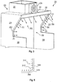
- an exhaust hood 100 has side skirts 106 and an exhaust collar 100 which is connectable to an exhaust duct (not shown) such that air and fumes are drawn into a recess 108 and out through the exhaust collar 110.
- a retrofit discharging module 140 has a fan module 101 containing a blower (not shown), that draws ambient room air into a duct 102 and passes the air into a distribution channel 104 pressurizing it such that air issues from an array of holes in the distribution channel 104 as individual air jets that expand due to air entrainment and coalesce a short distance thereafter to form a curtain jet 112.
- a cooking appliance top surface is indicated at 114.
- the retrofit discharging module 140 is attached to the exhaust hood 100 at its forward edge and requires only electrical connections to operate.
- the fan module 101 is provided with a flow controller, such as a damper or a speed controller, to permit the flow rate to be adjusted to fit the operating conditions of the hood 100 exhaust flow rate.
- the distribution channel 104 is a plenum.
- the holes (apertures) in the plenum 104 can be arranged so as to form substantially a straight line across a length of the plenum 104. The size of the holes and the distance between them can vary based on the particular application.
- the discharging plenum 104 can be configured to be tilted with respect to the forward edge of the exhaust hood. This can change the direction in which the holes are facing the cooking appliance, and thus the direction of the curtain jet 112.
- the direction of the curtain jet 112 can be changed to be anything between a substantially vertical and a substantially horizontal direction.
- the curtain jet 231 is shown forming an angle intermediate between the vertical and horizontal. This configuration may be used in embodiments where the exhaust hood 234 protects a platen grill 232 having a platen 230. The angle may be chosen such that the jet 231 clears a forward edge 235 of the platen 230 when the platen 230 is in a raised position.
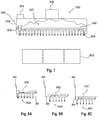
- an exhaust hood 200 has side panels (the panels are sometimes called skirts) 208 and an exhaust collar 201 which is connectable to an exhaust duct (not shown) such that air and fumes are drawn into a recess 209 and out through the exhaust collar 201.
- a capture augmentation device 260 has a fan module 204 containing a blower (not shown separately), that draws ambient room air into a duct 205 and passes the air into a distribution plenum 206 such that the air issues from an array of holes in the plenum 206 forming a curtain jet 212.
- the plenum 206, and similar elements with jet-forming holes in them, is also referred to as a header.
- a cooking appliance such as a fryer or other kitchen appliance, may be located beneath the recess 209.
- the capture augmentation device 260 is attached to the hood 200 at its forward edge and requires only electrical connections to operate.
- the fan module 204 is provided with a flow controller, such as a damper or a speed controller, to permit the flow rate to be adjusted to fit the operating conditions of the hood 200 exhaust flow rate.
- a perimeter 250 of the exhaust hood includes a forward edge 254 and at least one descending side edge 252 of the hood.
- the side skirts 208 of this embodiment have cut-out areas 210 shaped and sized to permit cooking implements, such as fryer baskets to be moved away from the fryer (not shown) which would reside below the recess 209.
- Descending plenums 202 with arrays of holes are connected to receive air from the plenum 206 and thereby form curtain jets 214 as shown.
- the curtain jets 214 effectively extend the effect of the side skirts 208 into the recess areas 210.
- the direction of the curtain jets may be altered according to various embodiments.
- the curtain jets 214 can be partially directed toward the opposite side panel 208 (that is, inwardly toward the middle of the recess) rather than parallel to the side panel 208 (i.e., in the plane of panel 208).
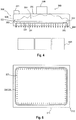
- an exhaust hood 300 has side walls 306 and a top wall 320 that together defines a recess 307 enclosed on all sides but an underside facing the one or more cooking appliances 400.
- the hood 300 has an exhaust collar 305 which is connectable to an exhaust duct (not shown) such that air and fumes are drawn into the recess 307 and out through the exhaust collar 305.
- a capture augmentation device 308 has a fan module 301 containing a blower (not shown separately), that draws ambient room into a duct 322 and passes the air into a distribution plenum 302 pressurizing it such that the air issues from an array of holes (for example, hole 324) forming vertical and horizontal curtain jets 304 and 326, respectively.
- the distribution plenum 302 has a cylindrical cross-section with straight and curved portions such that all sides of the canopy hood can be provided with the curtain jets shown.
- the fan module 301 is provided with a flow controller (not shown), such as a damper or a speed controller, to permit the flow rate to be adjusted to fit the operating conditions of the hood 300 exhaust flow rate.
- the distribution plenum 302 can be cylindrical as indicated at 303 with the array of holes 324 arranged in one or more substantially straight rows across a length of the plenum 302.
- the distribution plenum 302 is positioned within the recess 307 so as to extend along and substantially in parallel with the inside facing surface of at least one of the side walls 306.
- the tube 302 can be connected to the fan module 301 which is arranged external to the exhaust hood 300.
- the distribution plenum 302 can be offset upwardly from the bottom edge of the side wall and be offset horizontally from the inside surface of the side wall. The distance by which the discharging tube is offset from the edge and the side wall can vary depending on the application.
- the plurality of holes are positioned in a straight line facing the cooking appliance, so that the curtain jet 304 generated can be directed downwardly toward the cooking appliance in a substantially vertical direction.
- the discharging tube 302 can have a second set of plurality of holes positioned along the length of the tube 302, such that the first set of holes is substantially perpendicular to the second set of holes.
- a second curtain jet 311 is generated facing the inside of the recess 307 in a direction which is substantially horizontal.
- the exhaust hood may be a canopy-style hood.
- the tube 303 may be formed of a plurality of sections 400 each connectable to its own fan module 301, as shown in Fig. 5 .
- the distribution plenum 302 is tube positioned to extend along at least two adjacent inside surfaces of the exhaust hood 300 meeting at at least one corner.
- the distribution channel 302 has at least two straight tube portions 309 each extending along a respective inside surface of the exhaust hood 300.
- the two portions 309 are connected to each other through a curved tube portion 310 (or elbow).
- the curtain jet 311 generated in each of the straight tube portions 309 has a direction which is substantially horizontal and the curtain jet 312 generated in the curved tube portion 310 in angled relative to the direction of the curtain jet 311.
- Each of the straight tube portions 309 can be tilted relative to the curved tube portion 310.
- the distribution channel 302 is positioned so as to extend along the entire perimeter of the recess 307.
- the distribution channel may be a tube.
- the ambient air forced into one end 303 of the tube 302 may flow throughout the entire tube 302 so as to circumnavigate the entire exhaust hood 300 and generate curtain jets 311 and 312.
- the distribution plenum 502 has a box-shaped cross-section as indicated at 503.
- Other features are conform to the description of Fig. 4 .
- Figs. 8A, 8B, and 8C show various locations for the distribution plenum 502 (or 302).
- the plenum may be hung by hangers from within the canopy such that it does not touch the interior wall of the canopy as shown in Figs. 4 and 7 .
- it can be attached as shown in the Figs. 8A and 8C to the hood 820 interior.
- hangers similar to pipe hangers, for example
- the distribution plenum is shown below the lower edge 802 of the hood 800.
Landscapes
- Engineering & Computer Science (AREA)
- Chemical & Material Sciences (AREA)
- Combustion & Propulsion (AREA)
- Mechanical Engineering (AREA)
- General Engineering & Computer Science (AREA)
- Ventilation (AREA)
Claims (4)
- Hotte aspirante (200, 234) avec un dispositif d'amélioration de l'extraction (260), la hotte aspirante (200, 234) ayant une pluralité de bords (252, 254) qui définissent un périmètre avec un évidement (209) dans ce dernier pour capturer l'air contaminé d'un appareil de cuisson (232), et le dispositif d'amélioration de l'extraction (260) comprenant :un canal de distribution (206) configuré pour être fixé sur et s'étendre entièrement le long d'au moins l'un des bords de hotte aspirante (252, 254), le canal de distribution (206) ayant une entrée et une pluralité d'ouvertures s'étendant le long de sa longueur ; etune alimentation en air ambiant configurée pour fournir à l'entrée de canal de distribution, une alimentation en air ambiant sous pression, ledit dispositif d'amélioration de l'extraction produisant au moins un premier jet sous forme de rideau (212, 231) en faisant s'écouler l'air sous pression à travers ledit canal de distribution (206) et en le faisant sortir par la pluralité d'ouvertures, dans laquelle les ouvertures de canal de distribution sont orientées, à un angle, diagonalement vers le bas et à distance d'un intérieur de la hotte (200, 234), de sorte que le premier jet sous forme de rideau (212) est dirigé dans une direction correspondante à distance de l'intérieur de la hotte (200, 234) qui est entre une direction horizontale et une direction verticale,dans lequel le périmètre (250) de la hotte aspirante (200, 234) comprend un bord avant (254) et au moins deux bords latéraux descendants (252) de jupes latérales (208) avec des zones d'évidement (210) respectivement définies par une partie de bord latéral supérieur s'étendant diagonalement vers l'intérieur et vers le bas et une partie de bord latéral inférieur s'étendant verticalement depuis les au moins deux bords latéraux descendants (252),dans laquelle l'alimentation en air ambiant comprend un module de ventilateur (204) fixé au canal de distribution (206) et dans laquelle le dispositif d'amélioration de l'extraction est fixé de manière détachable au bord avant (254) du périmètre de la hotte aspirante (200, 234),dans laquelle le module de ventilateur (204) est positionné sur une surface externe de la hotte aspirante (200, 234) et comprend une grille d'entrée d'air et un ventilateur pour aspirer l'air ambiant par la grille d'entrée d'air, etdans laquelle le canal de distribution (206) s'étend en outre le long d'au moins une partie de chacun des au moins deux bords latéraux descendants (252), avec des plénums descendants (202), avec un réseau de trous, qui sont raccordés pour recevoir l'air du canal de distribution (206) et formant ainsi une pluralité de jets individuels, où ladite pluralité de jets individuels sur chacun des au moins deux bords latéraux descendants (252) forment un deuxième jet sous forme de rideau et un troisième jet sous forme de rideau (214) respectivement, étendant l'effet des jupes latérales (208) dans les zones d'évidement (210) et ont chacun une direction qui correspond à la forme du bord descendant (252) correspondant et leur position le long de ce dernier, moyennant quoi ces jets de la pluralité de jets individuels, qui sont prévus dans les parties de bord latéral inférieur s'étendant verticalement, soufflent dans une direction horizontale vers l'extérieur, et ces jets de la pluralité de jets individuels qui sont prévus dans les parties de bord latéral supérieur s'étendant diagonalement vers l'intérieur et vers le bas, soufflent dans une direction diagonale vers l'extérieur et vers le bas.
- Hotte aspirante (200, 234) selon l'une quelconque des revendications ci-dessus, dans laquelle le module de ventilateur (204) de l'alimentation en air ambiant a un organe de commande de vitesse configuré pour modifier un débit d'air.
- Hotte aspirante (200, 234) selon l'une quelconque des revendications ci-dessus, où la hotte (200, 234) recouvre un appareil (232) avec un plateau mobile (230), l'au moins un premier jet sous forme de rideau (231) fait saillie à un angle choisi pour diriger le jet sous forme de rideau immédiatement au-dessus du plateau (230) lorsque le plateau (232) est ouvert.
- Hotte aspirante (200, 234) selon l'une quelconque des revendications ci-dessus, dans laquelle le canal de distribution (206) est positionné de sorte qu'il étend la hotte aspirante (200, 234) lorsqu'il est fixé à cette dernière.
Priority Applications (1)
| Application Number | Priority Date | Filing Date | Title |
|---|---|---|---|
| PL09701561T PL2240726T3 (pl) | 2008-01-18 | 2009-01-19 | Okap wyciągowy z urządzeniem poprawiającym wyciąganie |
Applications Claiming Priority (2)
| Application Number | Priority Date | Filing Date | Title |
|---|---|---|---|
| US2230208P | 2008-01-18 | 2008-01-18 | |
| PCT/US2009/031415 WO2009092077A1 (fr) | 2008-01-18 | 2009-01-19 | Dispositifs de hottes, procédés, et systèmes dotés de caractéristiques pour améliorer la capture et la contention |
Publications (3)
| Publication Number | Publication Date |
|---|---|
| EP2240726A1 EP2240726A1 (fr) | 2010-10-20 |
| EP2240726A4 EP2240726A4 (fr) | 2011-09-07 |
| EP2240726B1 true EP2240726B1 (fr) | 2019-06-12 |
Family
ID=40885678
Family Applications (1)
| Application Number | Title | Priority Date | Filing Date |
|---|---|---|---|
| EP09701561.4A Active EP2240726B1 (fr) | 2008-01-18 | 2009-01-19 | Hotte aspirante avec dispositif d'amélioration de l'extraction |
Country Status (11)
| Country | Link |
|---|---|
| US (1) | US9835338B2 (fr) |
| EP (1) | EP2240726B1 (fr) |
| JP (1) | JP5452503B2 (fr) |
| AU (1) | AU2009205965B2 (fr) |
| BR (1) | BRPI0906738A2 (fr) |
| CA (2) | CA2911073C (fr) |
| DK (1) | DK2240726T3 (fr) |
| MX (2) | MX2010007817A (fr) |
| PL (1) | PL2240726T3 (fr) |
| WO (1) | WO2009092077A1 (fr) |
| ZA (1) | ZA201005291B (fr) |
Families Citing this family (24)
| Publication number | Priority date | Publication date | Assignee | Title |
|---|---|---|---|---|
| CA2573955C (fr) | 2004-07-23 | 2013-12-17 | Halton Company | Regulation amelioree de systemes d'echappement |
| CA2793796C (fr) * | 2006-04-18 | 2016-07-05 | Oy Halton Group, Ltd. | Unite murale modulaire comportant une petite hotte d'evacuation |
| US20080274683A1 (en) | 2007-05-04 | 2008-11-06 | Current Energy Controls, Lp | Autonomous Ventilation System |
| US20090061752A1 (en) | 2007-08-28 | 2009-03-05 | Current Energy Controls, Lp | Autonomous Ventilation System |
| JP2011518306A (ja) | 2008-04-18 | 2011-06-23 | オーワイ ハルトン グループ リミテッド | 増強捕捉及び封じ込め用排気装置、システム及び方法 |
| CN102301187A (zh) | 2008-12-03 | 2011-12-28 | 奥义霍尔顿集团有限公司 | 排气流控制系统和方法 |
| IN2012DN06308A (fr) * | 2010-01-13 | 2015-09-25 | Halton Group Ltd Oy | |
| TWI408317B (zh) * | 2010-12-15 | 2013-09-11 | Univ Nat Taiwan Science Tech | 具有抗擾動氣流能力的排油煙機 |
| US9909765B2 (en) | 2011-07-07 | 2018-03-06 | Oy Halton Group Ltd. | Exhaust hood methods, devices, and systems |
| KR101934457B1 (ko) * | 2011-11-17 | 2019-01-04 | 삼성전자주식회사 | 환기 장치와 이를 포함한 환기 시스템 |
| CN103343998A (zh) * | 2013-07-25 | 2013-10-09 | 浙江奥田电器有限公司 | 一种集成灶 |
| TWI550236B (zh) * | 2014-02-14 | 2016-09-21 | rong-fang Huang | Fume exclusion device |
| USD751684S1 (en) * | 2014-03-13 | 2016-03-15 | Oy Halton Group Ltd | Recirculating hood |
| US9541296B2 (en) * | 2014-05-22 | 2017-01-10 | National Taiwan University Of Science And Technology | Soot-exhausting device |
| CN104296211B (zh) * | 2014-09-03 | 2016-12-07 | 杭州老板电器股份有限公司 | 一种带有等离子净化的风幕烟机 |
| CN105605643B (zh) * | 2016-03-04 | 2018-02-27 | 珠海格力电器股份有限公司 | 出风结构及具有其的抽油烟机 |
| JP2018031515A (ja) * | 2016-08-24 | 2018-03-01 | 株式会社ネイブヒート | 空気清浄化装置及びそれを用いた空気清浄化方法 |
| US10610817B2 (en) * | 2016-11-02 | 2020-04-07 | Jawn P. Swan | Cleanroom workstation particle capture system |
| JP6824139B2 (ja) * | 2017-10-30 | 2021-02-03 | 大阪瓦斯株式会社 | 調理排気排出装置 |
| CN107781886B (zh) * | 2017-11-27 | 2019-07-19 | 杨肇 | 一种零和式低碳油烟净化器及净化系统 |
| US10578315B2 (en) * | 2017-12-21 | 2020-03-03 | Franke Technology And Trademark Ltd | Exhaust hood with forced air injection |
| KR101985797B1 (ko) * | 2018-12-26 | 2019-09-03 | 삼성전자주식회사 | 환기 장치와 이를 포함한 환기 시스템 |
| AU2020256238A1 (en) * | 2019-04-04 | 2021-10-14 | Oy Halton Group Ltd. | Slide-type range hood |
| US20210396394A1 (en) * | 2020-06-19 | 2021-12-23 | Dynamic HVAC Supply Ltd. | Kitchen exhaust recovery system |
Citations (7)
| Publication number | Priority date | Publication date | Assignee | Title |
|---|---|---|---|---|
| CN2128999Y (zh) * | 1992-09-05 | 1993-03-31 | 曾皞 | 风幕式排油烟装置 |
| CH682512A5 (de) * | 1990-03-02 | 1993-09-30 | Zurecon Ag | Dampfabzugeinrichtung. |
| US5251066A (en) * | 1992-11-12 | 1993-10-05 | Paul Appelbaum | Bathroom mirror demister |
| CN2211026Y (zh) * | 1994-11-30 | 1995-10-25 | 江照政 | 一种带旋转风幕的排油烟机 |
| US6450879B1 (en) * | 2001-10-29 | 2002-09-17 | Yeong-Nian Suen | Air curtain generator |
| CN1609517A (zh) * | 2004-09-17 | 2005-04-27 | 李水源 | 导烟机结构 |
| US20060090746A1 (en) * | 2004-11-03 | 2006-05-04 | Shuei-Yuan Lee | Smoke guiding machine |
Family Cites Families (24)
| Publication number | Priority date | Publication date | Assignee | Title |
|---|---|---|---|---|
| US3270655A (en) * | 1964-03-25 | 1966-09-06 | Howard P Guirl | Air curtain door seal |
| US3397631A (en) * | 1966-08-01 | 1968-08-20 | Dualjet Corp | Air curtain using ionized air |
| US3890887A (en) * | 1974-01-16 | 1975-06-24 | Elsters Inc | Exhaust hood |
| JPS54147647A (en) * | 1978-05-12 | 1979-11-19 | Hitachi Plant Eng & Constr Co Ltd | Exhaust hood |
| US4467782A (en) * | 1981-08-19 | 1984-08-28 | Russell Robert E | Ventilating system for use with devices which produce airborne impurities |
| DE8301489U1 (de) * | 1983-01-21 | 1983-06-16 | Helms, Henning, 2000 Hamburg, De | Kochherd |
| US4669373A (en) * | 1985-01-14 | 1987-06-02 | Restaurant Technology, Inc. | Two-sided cooking device for a grill |
| JPS62156739U (fr) * | 1986-03-27 | 1987-10-05 | ||
| DE3716257A1 (de) * | 1987-05-15 | 1988-11-24 | Takeo Imai | Verfahren und vorrichtung zum auffangen verschmutzter substanzen |
| JPS63286640A (ja) * | 1987-05-15 | 1988-11-24 | Matsushita Electric Works Ltd | 換気フ−ドの吸い込みガイド |
| US5160517A (en) * | 1990-11-21 | 1992-11-03 | Hicks Richard E | System for purifying air in a room |
| US6626971B1 (en) * | 1998-09-15 | 2003-09-30 | Siemens Axiva Gmbh & Co. Kg | Method and device for protecting persons and/or products from air-borne particles |
| US6044838A (en) | 1999-06-05 | 2000-04-04 | Deng; David | Fume exhaust apparatus for cooking stoves |
| US6851421B2 (en) | 2000-01-10 | 2005-02-08 | Halton Company | Exhaust hood with air curtain |
| EP1340024A4 (fr) * | 2000-08-10 | 2005-07-06 | Halton Company Inc | Dispositif et procede permettant de reguler/d'equilibrer le rapport debit-volume d'un fluide circulant dans des canaux d'ecoulement |
| JP2002130759A (ja) * | 2000-10-18 | 2002-05-09 | Royal Electric Co Ltd | レンジフードファン |
| US20110005507A9 (en) * | 2001-01-23 | 2011-01-13 | Rick Bagwell | Real-time control of exhaust flow |
| CA2536332A1 (fr) | 2003-08-13 | 2005-03-03 | Halton Company | Hotte a evacuation amelioree par configuration d'ajutages d'ecoulement |
| US6912864B2 (en) * | 2003-10-10 | 2005-07-05 | Hussmann Corporation | Evaporator for refrigerated merchandisers |
| JP4495474B2 (ja) * | 2004-02-02 | 2010-07-07 | 富士工業株式会社 | Ihクッキングヒータ用のレンジフード |
| KR100595573B1 (ko) | 2004-09-20 | 2006-07-03 | 엘지전자 주식회사 | 주방용 배기장치 |
| EP1893067B1 (fr) * | 2005-03-15 | 2017-08-16 | Enodis Corporation | Appareil et procédé de cuisson avec reconnaissance de produit |
| JP4730186B2 (ja) * | 2006-04-25 | 2011-07-20 | Toto株式会社 | レンジフード |
| CN1928440A (zh) * | 2006-06-30 | 2007-03-14 | 刘晓平 | 抽油烟机 |
-
2009
- 2009-01-19 CA CA2911073A patent/CA2911073C/fr active Active
- 2009-01-19 EP EP09701561.4A patent/EP2240726B1/fr active Active
- 2009-01-19 DK DK09701561.4T patent/DK2240726T3/da active
- 2009-01-19 US US12/863,122 patent/US9835338B2/en active Active
- 2009-01-19 BR BRPI0906738-8A patent/BRPI0906738A2/pt not_active IP Right Cessation
- 2009-01-19 WO PCT/US2009/031415 patent/WO2009092077A1/fr active Application Filing
- 2009-01-19 CA CA2712310A patent/CA2712310C/fr active Active
- 2009-01-19 MX MX2010007817A patent/MX2010007817A/es active IP Right Grant
- 2009-01-19 JP JP2010543302A patent/JP5452503B2/ja active Active
- 2009-01-19 AU AU2009205965A patent/AU2009205965B2/en active Active
- 2009-01-19 PL PL09701561T patent/PL2240726T3/pl unknown
- 2009-01-19 MX MX2014001498A patent/MX344997B/es unknown
-
2010
- 2010-07-23 ZA ZA2010/05291A patent/ZA201005291B/en unknown
Patent Citations (7)
| Publication number | Priority date | Publication date | Assignee | Title |
|---|---|---|---|---|
| CH682512A5 (de) * | 1990-03-02 | 1993-09-30 | Zurecon Ag | Dampfabzugeinrichtung. |
| CN2128999Y (zh) * | 1992-09-05 | 1993-03-31 | 曾皞 | 风幕式排油烟装置 |
| US5251066A (en) * | 1992-11-12 | 1993-10-05 | Paul Appelbaum | Bathroom mirror demister |
| CN2211026Y (zh) * | 1994-11-30 | 1995-10-25 | 江照政 | 一种带旋转风幕的排油烟机 |
| US6450879B1 (en) * | 2001-10-29 | 2002-09-17 | Yeong-Nian Suen | Air curtain generator |
| CN1609517A (zh) * | 2004-09-17 | 2005-04-27 | 李水源 | 导烟机结构 |
| US20060090746A1 (en) * | 2004-11-03 | 2006-05-04 | Shuei-Yuan Lee | Smoke guiding machine |
Also Published As
| Publication number | Publication date |
|---|---|
| JP5452503B2 (ja) | 2014-03-26 |
| CA2911073C (fr) | 2017-05-16 |
| CA2712310A1 (fr) | 2009-07-23 |
| AU2009205965A1 (en) | 2009-07-23 |
| EP2240726A4 (fr) | 2011-09-07 |
| US9835338B2 (en) | 2017-12-05 |
| BRPI0906738A2 (pt) | 2015-07-07 |
| US20110094497A1 (en) | 2011-04-28 |
| WO2009092077A1 (fr) | 2009-07-23 |
| MX2010007817A (es) | 2010-08-10 |
| CA2712310C (fr) | 2016-01-12 |
| EP2240726A1 (fr) | 2010-10-20 |
| ZA201005291B (en) | 2015-01-28 |
| PL2240726T3 (pl) | 2019-11-29 |
| MX344997B (es) | 2017-01-13 |
| DK2240726T3 (da) | 2019-09-02 |
| JP2011510259A (ja) | 2011-03-31 |
| CA2911073A1 (fr) | 2009-07-23 |
| AU2009205965B2 (en) | 2014-02-06 |
Similar Documents
| Publication | Publication Date | Title |
|---|---|---|
| EP2240726B1 (fr) | Hotte aspirante avec dispositif d'amélioration de l'extraction | |
| KR101641389B1 (ko) | 배기 장치, 시스템, 및 포획력과 봉쇄력을 향상시키는 방법 | |
| US10900665B2 (en) | Combination appliance having a cooktop and steam extraction device | |
| US8857424B2 (en) | Exhaust hood with adjustable supply air containment air streams and air curtains | |
| EP2175204A1 (fr) | Dispositif d'élimination de polluants et hotte de cuisine à rideau d'air unique oblique utilisant le dispositif | |
| CN111492181B (zh) | 具有强制空气喷射的排气罩 | |
| WO2015057072A1 (fr) | Hotte d'extraction d'air de cuisine ayant une cavité ayant une paroi de délimitation permettant le guidage et l'orientation d'air | |
| CN113167482A (zh) | 抽油烟机和具有抽油烟机的厨房装置 | |
| US20230175702A1 (en) | Extractor apparatus, and kitchen arrangement having a hob and an extractor apparatus | |
| KR20240107719A (ko) | 리턴 채널구조를 구비한 에어후드 | |
| AU2014271273A1 (en) | Exhaust apparatus, system, and method for enhanced capture and containment | |
| JPH03291423A (ja) | 加熱調理装置 | |
| KR20100003806A (ko) | 오염물질 제거장치 및 그 장치를 이용한 이중-공기커튼랜지후드 |
Legal Events
| Date | Code | Title | Description |
|---|---|---|---|
| PUAI | Public reference made under article 153(3) epc to a published international application that has entered the european phase |
Free format text: ORIGINAL CODE: 0009012 |
|
| 17P | Request for examination filed |
Effective date: 20100727 |
|
| AK | Designated contracting states |
Kind code of ref document: A1 Designated state(s): AT BE BG CH CY CZ DE DK EE ES FI FR GB GR HR HU IE IS IT LI LT LU LV MC MK MT NL NO PL PT RO SE SI SK TR |
|
| AX | Request for extension of the european patent |
Extension state: AL BA RS |
|
| DAX | Request for extension of the european patent (deleted) | ||
| A4 | Supplementary search report drawn up and despatched |
Effective date: 20110808 |
|
| RIC1 | Information provided on ipc code assigned before grant |
Ipc: F24C 15/20 20060101AFI20110802BHEP |
|
| 17Q | First examination report despatched |
Effective date: 20160510 |
|
| STAA | Information on the status of an ep patent application or granted ep patent |
Free format text: STATUS: EXAMINATION IS IN PROGRESS |
|
| GRAP | Despatch of communication of intention to grant a patent |
Free format text: ORIGINAL CODE: EPIDOSNIGR1 |
|
| STAA | Information on the status of an ep patent application or granted ep patent |
Free format text: STATUS: GRANT OF PATENT IS INTENDED |
|
| INTG | Intention to grant announced |
Effective date: 20190103 |
|
| GRAS | Grant fee paid |
Free format text: ORIGINAL CODE: EPIDOSNIGR3 |
|
| GRAA | (expected) grant |
Free format text: ORIGINAL CODE: 0009210 |
|
| STAA | Information on the status of an ep patent application or granted ep patent |
Free format text: STATUS: THE PATENT HAS BEEN GRANTED |
|
| AK | Designated contracting states |
Kind code of ref document: B1 Designated state(s): AT BE BG CH CY CZ DE DK EE ES FI FR GB GR HR HU IE IS IT LI LT LU LV MC MK MT NL NO PL PT RO SE SI SK TR |
|
| REG | Reference to a national code |
Ref country code: GB Ref legal event code: FG4D |
|
| REG | Reference to a national code |
Ref country code: CH Ref legal event code: EP |
|
| REG | Reference to a national code |
Ref country code: AT Ref legal event code: REF Ref document number: 1143059 Country of ref document: AT Kind code of ref document: T Effective date: 20190615 |
|
| REG | Reference to a national code |
Ref country code: DE Ref legal event code: R096 Ref document number: 602009058690 Country of ref document: DE |
|
| REG | Reference to a national code |
Ref country code: IE Ref legal event code: FG4D |
|
| REG | Reference to a national code |
Ref country code: CH Ref legal event code: NV Representative=s name: E. BLUM AND CO. AG PATENT- UND MARKENANWAELTE , CH |
|
| REG | Reference to a national code |
Ref country code: NL Ref legal event code: FP |
|
| REG | Reference to a national code |
Ref country code: DK Ref legal event code: T3 Effective date: 20190827 |
|
| REG | Reference to a national code |
Ref country code: SE Ref legal event code: TRGR |
|
| REG | Reference to a national code |
Ref country code: NO Ref legal event code: T2 Effective date: 20190612 |
|
| REG | Reference to a national code |
Ref country code: LT Ref legal event code: MG4D |
|
| PG25 | Lapsed in a contracting state [announced via postgrant information from national office to epo] |
Ref country code: ES Free format text: LAPSE BECAUSE OF FAILURE TO SUBMIT A TRANSLATION OF THE DESCRIPTION OR TO PAY THE FEE WITHIN THE PRESCRIBED TIME-LIMIT Effective date: 20190612 Ref country code: HR Free format text: LAPSE BECAUSE OF FAILURE TO SUBMIT A TRANSLATION OF THE DESCRIPTION OR TO PAY THE FEE WITHIN THE PRESCRIBED TIME-LIMIT Effective date: 20190612 Ref country code: LT Free format text: LAPSE BECAUSE OF FAILURE TO SUBMIT A TRANSLATION OF THE DESCRIPTION OR TO PAY THE FEE WITHIN THE PRESCRIBED TIME-LIMIT Effective date: 20190612 |
|
| PG25 | Lapsed in a contracting state [announced via postgrant information from national office to epo] |
Ref country code: GR Free format text: LAPSE BECAUSE OF FAILURE TO SUBMIT A TRANSLATION OF THE DESCRIPTION OR TO PAY THE FEE WITHIN THE PRESCRIBED TIME-LIMIT Effective date: 20190913 Ref country code: BG Free format text: LAPSE BECAUSE OF FAILURE TO SUBMIT A TRANSLATION OF THE DESCRIPTION OR TO PAY THE FEE WITHIN THE PRESCRIBED TIME-LIMIT Effective date: 20190912 Ref country code: LV Free format text: LAPSE BECAUSE OF FAILURE TO SUBMIT A TRANSLATION OF THE DESCRIPTION OR TO PAY THE FEE WITHIN THE PRESCRIBED TIME-LIMIT Effective date: 20190612 |
|
| PG25 | Lapsed in a contracting state [announced via postgrant information from national office to epo] |
Ref country code: PT Free format text: LAPSE BECAUSE OF FAILURE TO SUBMIT A TRANSLATION OF THE DESCRIPTION OR TO PAY THE FEE WITHIN THE PRESCRIBED TIME-LIMIT Effective date: 20191014 Ref country code: SK Free format text: LAPSE BECAUSE OF FAILURE TO SUBMIT A TRANSLATION OF THE DESCRIPTION OR TO PAY THE FEE WITHIN THE PRESCRIBED TIME-LIMIT Effective date: 20190612 Ref country code: CZ Free format text: LAPSE BECAUSE OF FAILURE TO SUBMIT A TRANSLATION OF THE DESCRIPTION OR TO PAY THE FEE WITHIN THE PRESCRIBED TIME-LIMIT Effective date: 20190612 Ref country code: EE Free format text: LAPSE BECAUSE OF FAILURE TO SUBMIT A TRANSLATION OF THE DESCRIPTION OR TO PAY THE FEE WITHIN THE PRESCRIBED TIME-LIMIT Effective date: 20190612 Ref country code: RO Free format text: LAPSE BECAUSE OF FAILURE TO SUBMIT A TRANSLATION OF THE DESCRIPTION OR TO PAY THE FEE WITHIN THE PRESCRIBED TIME-LIMIT Effective date: 20190612 |
|
| PG25 | Lapsed in a contracting state [announced via postgrant information from national office to epo] |
Ref country code: IS Free format text: LAPSE BECAUSE OF FAILURE TO SUBMIT A TRANSLATION OF THE DESCRIPTION OR TO PAY THE FEE WITHIN THE PRESCRIBED TIME-LIMIT Effective date: 20191012 |
|
| REG | Reference to a national code |
Ref country code: DE Ref legal event code: R097 Ref document number: 602009058690 Country of ref document: DE |
|
| PG25 | Lapsed in a contracting state [announced via postgrant information from national office to epo] |
Ref country code: TR Free format text: LAPSE BECAUSE OF FAILURE TO SUBMIT A TRANSLATION OF THE DESCRIPTION OR TO PAY THE FEE WITHIN THE PRESCRIBED TIME-LIMIT Effective date: 20190612 |
|
| PLBE | No opposition filed within time limit |
Free format text: ORIGINAL CODE: 0009261 |
|
| STAA | Information on the status of an ep patent application or granted ep patent |
Free format text: STATUS: NO OPPOSITION FILED WITHIN TIME LIMIT |
|
| 26N | No opposition filed |
Effective date: 20200313 |
|
| PG25 | Lapsed in a contracting state [announced via postgrant information from national office to epo] |
Ref country code: SI Free format text: LAPSE BECAUSE OF FAILURE TO SUBMIT A TRANSLATION OF THE DESCRIPTION OR TO PAY THE FEE WITHIN THE PRESCRIBED TIME-LIMIT Effective date: 20190612 Ref country code: IS Free format text: LAPSE BECAUSE OF FAILURE TO SUBMIT A TRANSLATION OF THE DESCRIPTION OR TO PAY THE FEE WITHIN THE PRESCRIBED TIME-LIMIT Effective date: 20200224 |
|
| PG2D | Information on lapse in contracting state deleted |
Ref country code: IS |
|
| PG25 | Lapsed in a contracting state [announced via postgrant information from national office to epo] |
Ref country code: IS Free format text: LAPSE BECAUSE OF FAILURE TO SUBMIT A TRANSLATION OF THE DESCRIPTION OR TO PAY THE FEE WITHIN THE PRESCRIBED TIME-LIMIT Effective date: 20191112 |
|
| PG25 | Lapsed in a contracting state [announced via postgrant information from national office to epo] |
Ref country code: MC Free format text: LAPSE BECAUSE OF FAILURE TO SUBMIT A TRANSLATION OF THE DESCRIPTION OR TO PAY THE FEE WITHIN THE PRESCRIBED TIME-LIMIT Effective date: 20190612 |
|
| REG | Reference to a national code |
Ref country code: BE Ref legal event code: MM Effective date: 20200131 |
|
| PG25 | Lapsed in a contracting state [announced via postgrant information from national office to epo] |
Ref country code: LU Free format text: LAPSE BECAUSE OF NON-PAYMENT OF DUE FEES Effective date: 20200119 |
|
| PG25 | Lapsed in a contracting state [announced via postgrant information from national office to epo] |
Ref country code: BE Free format text: LAPSE BECAUSE OF NON-PAYMENT OF DUE FEES Effective date: 20200131 |
|
| PG25 | Lapsed in a contracting state [announced via postgrant information from national office to epo] |
Ref country code: IE Free format text: LAPSE BECAUSE OF NON-PAYMENT OF DUE FEES Effective date: 20200119 |
|
| REG | Reference to a national code |
Ref country code: AT Ref legal event code: UEP Ref document number: 1143059 Country of ref document: AT Kind code of ref document: T Effective date: 20190612 |
|
| PG25 | Lapsed in a contracting state [announced via postgrant information from national office to epo] |
Ref country code: MT Free format text: LAPSE BECAUSE OF FAILURE TO SUBMIT A TRANSLATION OF THE DESCRIPTION OR TO PAY THE FEE WITHIN THE PRESCRIBED TIME-LIMIT Effective date: 20190612 Ref country code: CY Free format text: LAPSE BECAUSE OF FAILURE TO SUBMIT A TRANSLATION OF THE DESCRIPTION OR TO PAY THE FEE WITHIN THE PRESCRIBED TIME-LIMIT Effective date: 20190612 |
|
| PG25 | Lapsed in a contracting state [announced via postgrant information from national office to epo] |
Ref country code: MK Free format text: LAPSE BECAUSE OF FAILURE TO SUBMIT A TRANSLATION OF THE DESCRIPTION OR TO PAY THE FEE WITHIN THE PRESCRIBED TIME-LIMIT Effective date: 20190612 |
|
| P01 | Opt-out of the competence of the unified patent court (upc) registered |
Effective date: 20230505 |
|
| PGFP | Annual fee paid to national office [announced via postgrant information from national office to epo] |
Ref country code: NL Payment date: 20240126 Year of fee payment: 16 |
|
| PGFP | Annual fee paid to national office [announced via postgrant information from national office to epo] |
Ref country code: AT Payment date: 20240104 Year of fee payment: 16 |
|
| PGFP | Annual fee paid to national office [announced via postgrant information from national office to epo] |
Ref country code: FI Payment date: 20240125 Year of fee payment: 16 Ref country code: DE Payment date: 20240129 Year of fee payment: 16 Ref country code: GB Payment date: 20240129 Year of fee payment: 16 Ref country code: CH Payment date: 20240202 Year of fee payment: 16 |
|
| PGFP | Annual fee paid to national office [announced via postgrant information from national office to epo] |
Ref country code: SE Payment date: 20240127 Year of fee payment: 16 Ref country code: PL Payment date: 20240109 Year of fee payment: 16 Ref country code: NO Payment date: 20240129 Year of fee payment: 16 Ref country code: IT Payment date: 20240122 Year of fee payment: 16 Ref country code: FR Payment date: 20240125 Year of fee payment: 16 Ref country code: DK Payment date: 20240125 Year of fee payment: 16 |