EP2240283B1 - Non-contact edge coating apparatus for solar cell substrates - Google Patents
Non-contact edge coating apparatus for solar cell substrates Download PDFInfo
- Publication number
- EP2240283B1 EP2240283B1 EP20090707313 EP09707313A EP2240283B1 EP 2240283 B1 EP2240283 B1 EP 2240283B1 EP 20090707313 EP20090707313 EP 20090707313 EP 09707313 A EP09707313 A EP 09707313A EP 2240283 B1 EP2240283 B1 EP 2240283B1
- Authority
- EP
- European Patent Office
- Prior art keywords
- substrate
- edge
- coating material
- coating
- roller
- Prior art date
- Legal status (The legal status is an assumption and is not a legal conclusion. Google has not performed a legal analysis and makes no representation as to the accuracy of the status listed.)
- Active
Links
- 239000000758 substrate Substances 0.000 title claims description 176
- 238000000576 coating method Methods 0.000 title claims description 128
- 239000011248 coating agent Substances 0.000 title claims description 109
- 239000000463 material Substances 0.000 claims description 70
- 238000007747 plating Methods 0.000 claims description 10
- 239000012943 hotmelt Substances 0.000 claims description 7
- 238000000034 method Methods 0.000 description 9
- 238000001723 curing Methods 0.000 description 7
- 239000004065 semiconductor Substances 0.000 description 6
- 238000009792 diffusion process Methods 0.000 description 4
- 238000013459 approach Methods 0.000 description 3
- 239000012636 effector Substances 0.000 description 3
- 230000033001 locomotion Effects 0.000 description 3
- 238000004519 manufacturing process Methods 0.000 description 3
- 238000010586 diagram Methods 0.000 description 2
- 238000005530 etching Methods 0.000 description 2
- 239000007788 liquid Substances 0.000 description 2
- 239000002184 metal Substances 0.000 description 2
- 230000005855 radiation Effects 0.000 description 2
- 238000003848 UV Light-Curing Methods 0.000 description 1
- 230000007423 decrease Effects 0.000 description 1
- 230000001419 dependent effect Effects 0.000 description 1
- 238000001035 drying Methods 0.000 description 1
- 230000004927 fusion Effects 0.000 description 1
- 238000002955 isolation Methods 0.000 description 1
- 238000011068 loading method Methods 0.000 description 1
- 238000001465 metallisation Methods 0.000 description 1
- 229910001220 stainless steel Inorganic materials 0.000 description 1
- 239000010935 stainless steel Substances 0.000 description 1
Images


Classifications
-
- B—PERFORMING OPERATIONS; TRANSPORTING
- B05—SPRAYING OR ATOMISING IN GENERAL; APPLYING FLUENT MATERIALS TO SURFACES, IN GENERAL
- B05C—APPARATUS FOR APPLYING FLUENT MATERIALS TO SURFACES, IN GENERAL
- B05C1/00—Apparatus in which liquid or other fluent material is applied to the surface of the work by contact with a member carrying the liquid or other fluent material, e.g. a porous member loaded with a liquid to be applied as a coating
- B05C1/04—Apparatus in which liquid or other fluent material is applied to the surface of the work by contact with a member carrying the liquid or other fluent material, e.g. a porous member loaded with a liquid to be applied as a coating for applying liquid or other fluent material to work of indefinite length
- B05C1/08—Apparatus in which liquid or other fluent material is applied to the surface of the work by contact with a member carrying the liquid or other fluent material, e.g. a porous member loaded with a liquid to be applied as a coating for applying liquid or other fluent material to work of indefinite length using a roller or other rotating member which contacts the work along a generating line
- B05C1/0804—Apparatus in which liquid or other fluent material is applied to the surface of the work by contact with a member carrying the liquid or other fluent material, e.g. a porous member loaded with a liquid to be applied as a coating for applying liquid or other fluent material to work of indefinite length using a roller or other rotating member which contacts the work along a generating line the material being applied without contact with the roller
-
- B—PERFORMING OPERATIONS; TRANSPORTING
- B05—SPRAYING OR ATOMISING IN GENERAL; APPLYING FLUENT MATERIALS TO SURFACES, IN GENERAL
- B05C—APPARATUS FOR APPLYING FLUENT MATERIALS TO SURFACES, IN GENERAL
- B05C1/00—Apparatus in which liquid or other fluent material is applied to the surface of the work by contact with a member carrying the liquid or other fluent material, e.g. a porous member loaded with a liquid to be applied as a coating
- B05C1/006—Apparatus in which liquid or other fluent material is applied to the surface of the work by contact with a member carrying the liquid or other fluent material, e.g. a porous member loaded with a liquid to be applied as a coating for applying liquid or other fluent material to the edges of essentially flat articles
-
- B—PERFORMING OPERATIONS; TRANSPORTING
- B05—SPRAYING OR ATOMISING IN GENERAL; APPLYING FLUENT MATERIALS TO SURFACES, IN GENERAL
- B05C—APPARATUS FOR APPLYING FLUENT MATERIALS TO SURFACES, IN GENERAL
- B05C1/00—Apparatus in which liquid or other fluent material is applied to the surface of the work by contact with a member carrying the liquid or other fluent material, e.g. a porous member loaded with a liquid to be applied as a coating
- B05C1/04—Apparatus in which liquid or other fluent material is applied to the surface of the work by contact with a member carrying the liquid or other fluent material, e.g. a porous member loaded with a liquid to be applied as a coating for applying liquid or other fluent material to work of indefinite length
- B05C1/08—Apparatus in which liquid or other fluent material is applied to the surface of the work by contact with a member carrying the liquid or other fluent material, e.g. a porous member loaded with a liquid to be applied as a coating for applying liquid or other fluent material to work of indefinite length using a roller or other rotating member which contacts the work along a generating line
- B05C1/0813—Apparatus in which liquid or other fluent material is applied to the surface of the work by contact with a member carrying the liquid or other fluent material, e.g. a porous member loaded with a liquid to be applied as a coating for applying liquid or other fluent material to work of indefinite length using a roller or other rotating member which contacts the work along a generating line characterised by means for supplying liquid or other fluent material to the roller
-
- B—PERFORMING OPERATIONS; TRANSPORTING
- B05—SPRAYING OR ATOMISING IN GENERAL; APPLYING FLUENT MATERIALS TO SURFACES, IN GENERAL
- B05C—APPARATUS FOR APPLYING FLUENT MATERIALS TO SURFACES, IN GENERAL
- B05C1/00—Apparatus in which liquid or other fluent material is applied to the surface of the work by contact with a member carrying the liquid or other fluent material, e.g. a porous member loaded with a liquid to be applied as a coating
- B05C1/04—Apparatus in which liquid or other fluent material is applied to the surface of the work by contact with a member carrying the liquid or other fluent material, e.g. a porous member loaded with a liquid to be applied as a coating for applying liquid or other fluent material to work of indefinite length
- B05C1/08—Apparatus in which liquid or other fluent material is applied to the surface of the work by contact with a member carrying the liquid or other fluent material, e.g. a porous member loaded with a liquid to be applied as a coating for applying liquid or other fluent material to work of indefinite length using a roller or other rotating member which contacts the work along a generating line
- B05C1/0821—Apparatus in which liquid or other fluent material is applied to the surface of the work by contact with a member carrying the liquid or other fluent material, e.g. a porous member loaded with a liquid to be applied as a coating for applying liquid or other fluent material to work of indefinite length using a roller or other rotating member which contacts the work along a generating line characterised by driving means for rollers or work
-
- B—PERFORMING OPERATIONS; TRANSPORTING
- B05—SPRAYING OR ATOMISING IN GENERAL; APPLYING FLUENT MATERIALS TO SURFACES, IN GENERAL
- B05C—APPARATUS FOR APPLYING FLUENT MATERIALS TO SURFACES, IN GENERAL
- B05C11/00—Component parts, details or accessories not specifically provided for in groups B05C1/00 - B05C9/00
- B05C11/10—Storage, supply or control of liquid or other fluent material; Recovery of excess liquid or other fluent material
- B05C11/1002—Means for controlling supply, i.e. flow or pressure, of liquid or other fluent material to the applying apparatus, e.g. valves
- B05C11/1015—Means for controlling supply, i.e. flow or pressure, of liquid or other fluent material to the applying apparatus, e.g. valves responsive to a conditions of ambient medium or target, e.g. humidity, temperature ; responsive to position or movement of the coating head relative to the target
- B05C11/1021—Means for controlling supply, i.e. flow or pressure, of liquid or other fluent material to the applying apparatus, e.g. valves responsive to a conditions of ambient medium or target, e.g. humidity, temperature ; responsive to position or movement of the coating head relative to the target responsive to presence or shape of target
-
- B—PERFORMING OPERATIONS; TRANSPORTING
- B05—SPRAYING OR ATOMISING IN GENERAL; APPLYING FLUENT MATERIALS TO SURFACES, IN GENERAL
- B05C—APPARATUS FOR APPLYING FLUENT MATERIALS TO SURFACES, IN GENERAL
- B05C13/00—Means for manipulating or holding work, e.g. for separate articles
- B05C13/02—Means for manipulating or holding work, e.g. for separate articles for particular articles
-
- B—PERFORMING OPERATIONS; TRANSPORTING
- B05—SPRAYING OR ATOMISING IN GENERAL; APPLYING FLUENT MATERIALS TO SURFACES, IN GENERAL
- B05C—APPARATUS FOR APPLYING FLUENT MATERIALS TO SURFACES, IN GENERAL
- B05C9/00—Apparatus or plant for applying liquid or other fluent material to surfaces by means not covered by any preceding group, or in which the means of applying the liquid or other fluent material is not important
- B05C9/08—Apparatus or plant for applying liquid or other fluent material to surfaces by means not covered by any preceding group, or in which the means of applying the liquid or other fluent material is not important for applying liquid or other fluent material and performing an auxiliary operation
- B05C9/10—Apparatus or plant for applying liquid or other fluent material to surfaces by means not covered by any preceding group, or in which the means of applying the liquid or other fluent material is not important for applying liquid or other fluent material and performing an auxiliary operation the auxiliary operation being performed before the application
-
- H—ELECTRICITY
- H10—SEMICONDUCTOR DEVICES; ELECTRIC SOLID-STATE DEVICES NOT OTHERWISE PROVIDED FOR
- H10F—INORGANIC SEMICONDUCTOR DEVICES SENSITIVE TO INFRARED RADIATION, LIGHT, ELECTROMAGNETIC RADIATION OF SHORTER WAVELENGTH OR CORPUSCULAR RADIATION
- H10F71/00—Manufacture or treatment of devices covered by this subclass
-
- H—ELECTRICITY
- H10—SEMICONDUCTOR DEVICES; ELECTRIC SOLID-STATE DEVICES NOT OTHERWISE PROVIDED FOR
- H10F—INORGANIC SEMICONDUCTOR DEVICES SENSITIVE TO INFRARED RADIATION, LIGHT, ELECTROMAGNETIC RADIATION OF SHORTER WAVELENGTH OR CORPUSCULAR RADIATION
- H10F77/00—Constructional details of devices covered by this subclass
- H10F77/30—Coatings
- H10F77/306—Coatings for devices having potential barriers
-
- B—PERFORMING OPERATIONS; TRANSPORTING
- B05—SPRAYING OR ATOMISING IN GENERAL; APPLYING FLUENT MATERIALS TO SURFACES, IN GENERAL
- B05C—APPARATUS FOR APPLYING FLUENT MATERIALS TO SURFACES, IN GENERAL
- B05C1/00—Apparatus in which liquid or other fluent material is applied to the surface of the work by contact with a member carrying the liquid or other fluent material, e.g. a porous member loaded with a liquid to be applied as a coating
- B05C1/04—Apparatus in which liquid or other fluent material is applied to the surface of the work by contact with a member carrying the liquid or other fluent material, e.g. a porous member loaded with a liquid to be applied as a coating for applying liquid or other fluent material to work of indefinite length
- B05C1/08—Apparatus in which liquid or other fluent material is applied to the surface of the work by contact with a member carrying the liquid or other fluent material, e.g. a porous member loaded with a liquid to be applied as a coating for applying liquid or other fluent material to work of indefinite length using a roller or other rotating member which contacts the work along a generating line
- B05C1/0808—Details thereof, e.g. surface characteristics
-
- Y—GENERAL TAGGING OF NEW TECHNOLOGICAL DEVELOPMENTS; GENERAL TAGGING OF CROSS-SECTIONAL TECHNOLOGIES SPANNING OVER SEVERAL SECTIONS OF THE IPC; TECHNICAL SUBJECTS COVERED BY FORMER USPC CROSS-REFERENCE ART COLLECTIONS [XRACs] AND DIGESTS
- Y02—TECHNOLOGIES OR APPLICATIONS FOR MITIGATION OR ADAPTATION AGAINST CLIMATE CHANGE
- Y02E—REDUCTION OF GREENHOUSE GAS [GHG] EMISSIONS, RELATED TO ENERGY GENERATION, TRANSMISSION OR DISTRIBUTION
- Y02E10/00—Energy generation through renewable energy sources
- Y02E10/50—Photovoltaic [PV] energy
-
- Y—GENERAL TAGGING OF NEW TECHNOLOGICAL DEVELOPMENTS; GENERAL TAGGING OF CROSS-SECTIONAL TECHNOLOGIES SPANNING OVER SEVERAL SECTIONS OF THE IPC; TECHNICAL SUBJECTS COVERED BY FORMER USPC CROSS-REFERENCE ART COLLECTIONS [XRACs] AND DIGESTS
- Y02—TECHNOLOGIES OR APPLICATIONS FOR MITIGATION OR ADAPTATION AGAINST CLIMATE CHANGE
- Y02P—CLIMATE CHANGE MITIGATION TECHNOLOGIES IN THE PRODUCTION OR PROCESSING OF GOODS
- Y02P70/00—Climate change mitigation technologies in the production process for final industrial or consumer products
- Y02P70/50—Manufacturing or production processes characterised by the final manufactured product
Definitions
- the present invention relates generally to solar cells, and more particularly but not exclusively to solar cell fabrication tools.
- Solar cells are well known devices for converting solar radiation to electrical energy. They may be fabricated on a solar cell substrate, such as a semiconductor wafer, using semiconductor processing technology.
- a solar cell includes P-type and N-type diffusion regions that form a junction. Solar radiation impinging on the solar cell creates electrons and holes that migrate to the diffusion regions, thereby creating voltage differentials between the diffusion regions.
- both the diffusion regions and the metal contacts coupled to them are on the backside of the solar cell. The metal contacts allow an external electrical circuit to be coupled to and be powered by the solar cell.
- An edge of a solar cell substrate may be coated with a dielectric for electrical isolation and to prevent metal deposition or growth on the substrate perimeter.
- the conventional approach for applying the coating material is to contact the edge of the substrate with a roller.
- the roller has a groove with a surface that is pushed against the edge of the substrate. Coating material supplied to the groove gets applied to the edge of the substrate when the roller and the substrate are rotated.
- the coating material may comprise thermal ink that needs to be cured in a large drying oven in a separate process step. The use of thermal ink thus necessitates relatively large capital investment due to the cost and large footprint of associated ovens.
- the materials deposited on the wafer surface in previous processing steps could be affected by exposure to the oven temperature.
- Other problems associated with previous approaches to edge coating include stress applied to the substrate by direct mechanical contact with the applicator and poor reliability of the edge coat in processes using thermal ink.
- US 4 968 375 A relates to an etching apparatus for etching an end surface of a semiconductor substrate.
- a non-contact edge coating apparatus applies coating material to an edge of a non-circular solar cell substrate without physical contact.
- the apparatus is defined in claim 1.
- the apparatus includes a rotatable substrate support configured to hold the substrate.
- the apparatus further includes an applicator configured to receive a coating material and apply the coating material to an edge of the substrate while the substrate is rotated without any portion of the applicator physically touching the edge of the substrate.
- the substrate support is mechanically coupled to a cam, which contacts a follower mechanically coupled to the applicator.
- a variety of coating materials may be employed with the apparatus including hot melt ink and UV curable plating resist.
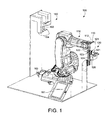
- FIG. 1 shows a perspective view of a non-contact edge coating system 100 for solar cell substrates in accordance with an embodiment of the present invention.
- the system 100 is specifically adapted to coat an edge of a solar cell substrate, which typically has a non-circular shape.
- a solar cell substrate When a solar cell substrate is rotated, its non-circular shape creates a trajectory that makes it relatively difficult to follow the edge of the substrate with an applicator.
- Conventional approaches to edge coating solar cell substrates get around this issue by physically contacting the edge with a roller supplying the coating material.
- the system 100 includes a transport 110, an applicator system 120, and a vision system 160.
- a coating material supply system for feeding coating material to the applicator system 120 is not shown in FIG. 1 for clarity of illustration.
- An example material supply system that may be used with the system 100 is later described with reference to FIG. 7 .
- Other material supply systems may also be used without detracting from the merits of the present invention.
- the transport 110 may comprise a handling mechanism for moving a non-circular solar cell substrate 101 between a pre-alignment station 163 (see also FIG. 2 ) and a position where the applicator system 120 can coat the edge of the substrate 101, which in one embodiment comprises a semiconductor wafer with a pseudo-square shape.
- the transport 110 comprises a commercially-available multi-axis robot.
- the transport 110 may have an end portion that includes a cam 112 and a substrate support in the form of a chuck 113 for holding the substrate 101.
- the cam 112 may have the same shape as the substrate 101 but may have different (e.g., smaller) dimensions.
- the chuck 113 may hold the substrate 101 by vacuum force or other means.
- the chuck 113 may comprise hardened stainless steel, for example.
- the transport 110 positions the cam 112 such that it is in contact with a follower 123 of the applicator system 120.
- the applicator system 120 comprises a mechanism for applying a coating material on the edge of the substrate 101.
- the applicator system 120 may comprise a coating applicator in the form of a roller 121, a rotational drive mechanism 122 configured to rotate the roller 121, and a slider assembly 124 configured to move the roller 121 towards and away from the substrate 101 along a single axis.
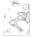
- the transport 110 positions the substrate 101 to meet the applicator 120 as shown in FIG. 1 .
- the slider assembly 124 moves up to push the follower 123 to contact the cam 112.
- An air spring 126 on the slider assembly 124 applies a relatively constant pressure on the follower 123 to contact the cam 112.
- the transport 110 rotates the substrate 101 to coat the edge of the substrate 101 with coating material from the roller 121.
- the drive mechanism 122 rotates the follower 123, which contacts and thereby follows the shape of the cam 112.
- the roller 121 is mechanically coupled to the follower 123 such that the roller 121 slides in and out by way of the air spring 126 in accordance with the mechanical interface between the follower 123 and the cam 112, thereby allowing the roller 121 to move in accordance with the shape of the substrate 101.
- the substrate 101 and the roller 121 may be rotated in the same or opposite direction with respect to each other at a speed that is dependent upon the ink type and properties (e.g., viscosity and adhesion). When rotating in opposite directions, a typical speed for the substrate 101 is 250deg/sec while for the roller 121 is 100-300RPM.
- the edge coating system 100 is "non-contact" in that the applicator, which is the roller 121 in this example, does not contact the edge of the substrate 101 during the edge coating process. In fact, in the example of FIG. 1 , no hardware component of the system 100 contacts the edge of the substrate 101 while coating material is applied thereto. Instead, the substrate 101 is positioned within a recessed portion of the roller 121 in the form of a groove 125 (see FIGS. 4A and 4B ) to receive edge coating material without any physical contact to the edge of the substrate 101. The coating material is applied to the groove 125 (see feed tube 411 in FIG. 4A ) and then transferred to the edge of the substrate 101 by presence of the edge in the groove 125. Rotation of the substrate 101 by the transport 110 allows the entire perimeter edge of the substrate 101 to be coated.
- the vision system 160 is configured to allow the transport 110 to correctly position the chuck 113 to pick up the substrate 101 from the station 163.
- the vision system 160 may comprise a camera 162, the station 163 and a lighting fixture 164.
- a computer system 161 is configured to control the operation of the system 100, including the vision system 160, the applicator system 120, and the transport 110. Some components of FIG. 1 are also shown in FIGS. 2 and 3 for clarity of illustration.
- the substrate 101 is positioned in the station 163 manually by a production operator or by an automated handling system (not shown).
- the station 163 is in a fixed coordinate relative to the transport 110 for ease of location.
- the station 163 is also shaped to allow the substrate 101 to be pre-aligned relative to the transport 110, simplifying pick-up and alignment of the substrate 101 with respect to the chuck 113 and thus cam 112.
- the vision system 160 takes an image of the substrate 101 in the station 163 and analyzes the image to find the center of the substrate surface and determine the orientation of the substrate 101.
- the computer 161 uses the information from the vision system 160 to allow the transport 110 to locate and pick up the substrate 101 such that the center of the surface area of the substrate 101 is coincident with the center of the surface area of the chuck 113. Having located and aligned the substrate 101 relative to the chuck 113, the transport 110 then picks up the substrate 101 as shown in FIG. 2 and positions it for edge coating with the applicator system 120 as shown in FIG. 3 . The transport 110 places the substrate 101 back to the station 163 after the edge coating process.
- the vision system 160 may be implemented using commercially available components without detracting from the merits of the present invention.
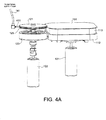
- FIG. 4A shows a perspective view of the roller 121 relative to the substrate 101 during the edge coating process.
- Coating material is supplied to the groove 125 of the roller 121 by way of a feed tube 411.
- the feed tube 411 receives coating material from a material supply tank (see 142 in FIG. 7 ) by way of a flexible supply tube 141.
- the drive 122 rotates the cam 123 and the roller 121 while coating material is fed to the groove 125.
- the substrate 101 is held by the chuck 113, which is mechanically coupled to the cam 112.
- a rotational drive 131 in the transport 110 rotates the cam 112 to thereby rotate the substrate 101.
- the edge of the substrate 101 is positioned in the groove 125 to receive coating material.
- the center of the substrate 101 is in a relatively fixed position during the edge coating process.
- the rotational drive 131 rotates the cam 112 together with the chuck 113 and the substrate 101.
- the air spring 126 pushes the follower 123 to follow the cam 112 such that the roller 121 follows the shape of the substrate 101.
- FIG. 4B shows a side view of the roller 121 relative to the substrate 101 during the edge coating process. Note that the edge of the substrate 101 does not physically contact the roller 121 during edge coating. Instead, the edge of the substrate 101 is received in the groove 125. Because the shape of the cam 112 approximates or is the same as the substrate 101, and the follower 123 is in mechanical contact with the cam 112, the roller 121 is able to apply coating material to the edge of the substrate 101 without physical contact.
- FIGS. 5A and 5B schematically show a side view and a top view, respectively, of the roller 121 relative to the substrate 101 during the edge coating process.
- FIG. 5B schematically shows the air spring 126 of the slider assembly 124 applying a relatively constant force to the follower 123, allowing the follower 123 to move to follow the shape of the cam 112.
- the edge of the substrate 101 is positioned in the groove 125 without touching a surface of the groove 125 or other portions of the roller 121.
- FIGS. 6A and 6B schematically show the principle of operation of a conventional air spring 126 that may be employed in embodiments of the present invention.
- the air spring 126 is configured to keep the pressure P1 and thus the force applied to the follower 123 relatively constant independent of the profile of the cam 112.
- the chamber 505 of the air spring 126 on the other side of the chamber 503 is at atmospheric pressure.
- FIG. 7 shows a perspective view of a coating material supply system in accordance with an embodiment of the present invention.
- the material supply system includes a material supply tank 142 containing the coating material. Coating material from the tank 142 is flowed to the feed tube 411 by way of a flexible supply tube 141.
- the feed tube 411 flows the coating material to the roller 121, which applies the coating material to the edge of the substrate 101 without physical contact.
- COATING WIDTH Wafer Diameter - CAM Diameter 2 - Follower Diameter - Roller Diameter 2 ⁇ distance between wafer surface center and cam surface center
- the coating width can be configured for a particular application by design choice of the cam diameter, follower diameter, roller diameter, and cam width for a given wafer diameter.
- the non-contact edge coating system 100 may employ various coating materials without detracting from the merits of the present invention.
- the edge coating system 100 may employ thermal ink.
- the edge coating system 100 employs a coating material that does not need to be cured or dried in a large oven.
- the coating material comprises hot melt ink comprising a wax, such as those available from SunJet.
- hot melt ink the tank 142 and associated hoses, tubing system, and feed tube are preferably heated.
- the coating material comprises a UV (ultraviolet) curable plating resist.
- UV curable plating resist may be cured by exposure to an LED (light emitting diode) system with a focused beam, such as a spot cure LED or a liquid light guide. Spot cure LED and liquid light guide are commercially available from, for example, UV Process Supply, Inc. Another possible curing method is provided by using commercially available UV lamps or bulbs from, for example, Fusion UV Systems Inc or Dymax Corporation.
- UV curable plating resist also referred to as "UV ink”
- UV ink has several advantages as an edge coating material for solar cells including low heat requirement to avoid liquefying hot melts deposited in previous processing steps and focused UV curing that is limited to a specific area to avoid UV exposure of the front of the solar cell.
- UV curable plating resist has the additional advantage of requiring a small curing component that can readily mounted in an applicator system.
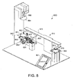
- FIG. 8 there is shown a non-contact edge coating system 800 in accordance with another embodiment of the present invention.
- the system 800 is non-contact in that it is configured to apply coating material to a non-circular solar cell substrate 801 without the applicator, a roller 821 in the example of FIG. 1 , physically touching the substrate 801.
- the system 800 positions the applicator relative to the substrate using electronic control means rather than a mechanical arrangement.
- the non-contact edge coating system 800 comprises a transport 810, an applicator system 820, a workpiece holding assembly 840, a control system 900 (see FIG. 12 ), a pre-alignment station 863, and curing components 851.
- a coating material supply system for feeding coating material to the applicator system 820 is not shown in FIG. 8 for clarity of illustration.
- An example material supply system that may be used with the system 800 is previously described with reference to FIG. 7 . Other material supply systems may also be used without detracting from the merits of the present invention.
- the transport 810 may comprise a handling mechanism for moving a non-circular solar cell substrate 801 between a pre-alignment station 863 and a position where the applicator system 820 can coat the edge of the substrate 801.
- the substrate 801 may comprise a semiconductor wafer having a pseudo-square shape.
- the transport 810 comprises a pick and place robot.
- the transport 810 may include a beam 873 and an arm 871 with an end-effector 872.
- the end-effector 872 may be lowered and raised to pick-up or place the substrate 801.
- the end-effector 872 may hold the substrate 801 by vacuum force.
- the substrate 801 may be positioned in a pre-alignment station 863 manually by a production operator or by an automated handling system (not shown).
- the station 863 is in a fixed coordinate relative to the transport 810 for ease of location.
- the station 863 is also shaped to allow the substrate 801 to be pre-aligned relative to the transport 810, simplifying pick-up and alignment of the substrate 801.
- the transport 810 picks up the substrate 801 from the station 863, slides along the beam 873 towards the applicator system 820, and then places the substrate 801 onto the holding assembly 840.
- the transport 810 performs the reverse operation to place the substrate 801 back into the station 863 after the edge coating process.
- the holding assembly 840 may be configured to support and hold the substrate 801.
- the holding assembly 840 may comprise a substrate support in the form of a chuck 843 for holding the substrate 801 by, for example, vacuum force.
- the holding assembly 840 may further include a rotational drive 842 for rotating the chuck 843, and thus the substrate 801, in place.
- the center of the chuck 843 may be in a fixed coordinate and accordingly does not move during edge coating.
- the applicator system 820 may comprise an applicator in the form of a roller 821, which rides on a single-axis slider assembly 824.
- the roller 821 includes a recessed portion in the form of a groove 825 (see FIGS. 11A and 11B ) that receives the edge of the substrate 801.
- the slider assembly 824 moves the roller 821 along a single axis to coat the edge of the substrate 801 without physically touching the edge of the substrate 801.
- the coating material is applied to the groove 825 (see feed tube 811 in FIG. 11A ) and then transferred to the edge of the substrate 801 by presence of the edge in the groove 825.
- the curing components 851 may comprise a spot cure LED or other means for curing UV curable plating resist used as coating material.
- Other coating materials, such as thermal ink and hot melt ink may also be used without detracting from the merits of the present invention.
- the control system 900 may include a camera 862 for taking images of the substrate 801 on the chuck 843, a lighting fixture 864 for providing a light source for the camera 862, and a computer 861 for processing images taken by the camera 862 and driving the slider assembly 824 towards and away from the substrate 801 such that the roller 821 applies coating material to the edge of the substrate 801 without physically contacting the edge of the substrate 801.
- the control system 900 is further described with reference to FIG. 12 .
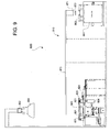
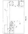
- FIGS. 9 and 10 show a side view and a top view, respectively, of the system 800.
- the components labeled in FIGS. 9 and 10 have been previously described with reference to FIG. 8 .
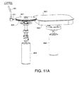
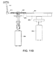
- FIGS. 11A and 11B show a perspective view and a side view, respectively, of the roller 821 relative to the substrate 801 during an edge coating process.
- Coating material is applied to the groove 825 by way of a feed tube 411, which receives coating material by way of the flexible supply tube 141 (see also FIG. 7 ).
- the edge of the substrate 801 receives the coating material in the groove 825.
- the chuck 843 is rotated by the rotational drive 842 (see FIGS. 8 and 9 ) to rotate the substrate 801, allowing the entire perimeter edge of the wafer to be coated with the coating material, at about 100-300 RPM 200-370degree/sec.
- the edge of the substrate 801 is received in the groove 825 but does not contact any portion of the roller 821 or any hardware component of the system 800 during the edge coating process.
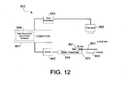
- FIG. 12 schematically shows the control system 900 for the non-contact edge coating system 800 in accordance with an embodiment of the present invention.
- the control system 900 includes the computer 861, the camera 862, a drive module 942, a data acquisition module 943, and corresponding data acquisition and control software 944.
- the data acquisition module 943 may be configured to receive images taken by the camera 862 and convert the images to a form that can be read and processed by the computer 861.
- the drive module 942 may be configured to receive control signals from the computer 861 for driving the slider assembly 942, and thus the roller 821 along a single axis.
- the data acquisition and control software 944 may comprise computer-readable program code for processing images taken by the camera 862 and outputting corresponding control signals to drive the roller 821.
- the control system 900 operates as a closed loop servo for driving the roller 821 towards and away from the substrate 801 to coat the edge of the substrate 801 without physical contact.
- the software 944 commands the data acquisition module 943 to take an image of the substrate 801 on the chuck 843 to locate points on the edge ("edge points") of the substrate 801.
- the software 944 keeps track of the edge points and sends corresponding control signals to the drive module 942 to move the slider assembly 824 such that the roller 821 follows the edge points at a coating distance given the rotational speed of the substrate 801.
- the control system 900 keeps a coating distance between the end surface of the groove 825 of the roller 821 and the edge of the substrate 801 despite the non-circular shape of the substrate 801.
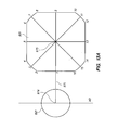
- FIGS. 13A , 13B , 13C , and 13D schematically illustrate the movement of the roller 821 along a single axis 971 during the edge coating process in accordance with an embodiment of the present invention.
- the control system 900 locates edge points 1-16 of the substrate 801 prior to edge coating.
- the center of the roller 821 is at a location 974 along the axis 971 (see also, position X0 on the horizontal axis), and is away from the substrate 801.
- the center 975 of the substrate 801 is at a fixed coordinate coincident with the axis 971.
- the control system 900 moves the roller 821 in a position to apply a coating material to the edge of the substrate 801.
- the roller 821 and the substrate 801 are then rotated in the same direction, which in this example is counter-clockwise (see arrow 951).
- the control system 900 positions the center of the roller 821 at a location 976 (see also, position X1 on the horizontal axis) along the axis 971 to have a coating distance with the edge of the substrate.
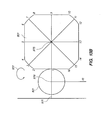
- the control system 900 keeps track of the edge points 1-16 during rotation of the substrate 801.
- control system 900 calculates and keeps track of the entire perimeter of the edge of the substrate 801 while it is rotated, and moves the roller 821 relative to the edge of the substrate 801 to maintain the coating distance without physically contacting the edge.
- FIG. 13C shows the center of the roller 821 moved by the control system 900 to a location 977 (see also, position X2 on the horizontal axis) on the axis 971 to make room for the edge point 2 when the substrate 801 rotates. This allows coating material to be applied from the roller 821 to the edge point 2 of the substrate 801 without physical contact between the edge point 2 and the roller 821.
- FIG. 13D shows the center of the roller 821 moved by the control system 900 to a location 978 (see also, position X3 on the horizontal axis) on the axis 971 when the substrate 801 rotates such that edge point 3 is on the axis 972.
- the control system 900 continually adjusts the roller 821 towards and away from the substrate 801 to maintain a coating distance with the substrate 801 to perform non-contact edge coating.
- FIG. 14 shows a flow diagram of a method 980 of coating an edge of a solar cell substrate in accordance with an embodiment of the present invention.
- the method 980 is explained using the components of the non-contact edge coating system 800 for illustration purposes only. Other components may also be used without detracting from the merits of the present invention.
- the method 980 begins by locating points on the edge of the substrate prior to starting the edge coating process (step 981).
- the transport 810 may pick up the substrate 801 from the pre-alignment station 863 and place the substrate 801 onto the chuck 843.
- the data acquisition and control software 944 may command the data acquisition module 953 to take an image of the substrate 801. From the image, the software 944 may locate points on the edge of the substrate.
- the edge points are then tracked during rotation of the substrate (step 982).
- the software 944 may continually receive images of the substrate 801 as it is rotated while held by the chuck 843.
- the substrate 801 is rotated about a fixed rotation axis which coordinate is known to the software 944.
- the software 944 can calculate the trajectory of the edge of the substrate 801, and thus how far the edge of the substrate 801 extends onto the single axis of motion of the roller 821. This allows the software 944 to determine a coating distance between the roller 821 and the edge of the substrate 801 while the roller 821 and the substrate 801 are rotated.
- the applicator applying the coating material to the edge of the substrate is moved along a single axis to maintain a coating distance with the edge of the substrate (step 983).
- the software 944 sends control signals to the drive module 942 to drive the slider assembly 824 such that there is a coating distance between a surface of the groove 825 (see FIG. 11A ) and the edge of the substrate 801 during rotation of the roller 821 and the substrate 801.
- the coating distance may be a predetermined constant distance or a range that allows for coating of the edge of the substrate 801.
- the edge of the substrate is coated with the coating material while the substrate is rotated (step 984).
- coating material may be applied on the groove 825 of the roller 821.
- the coating material on the groove 825 is then imparted on the edge of the substrate 801 as the roller 821 and the substrate 821 are rotated.
- the coating material may comprise thermal ink, hot melt ink, or, preferably, UV curable plating resist.
- the coating material may be cured while the substrate is on the substrate support (step 985). This is an optional step applicable when using, for example, UV curable plating resist.
- the curing components 851 are activated to cure the UV curable plating resist coated on the edge of the substrate 801 while the substrate 801 is still on the chuck 843. This allows the coating and curing steps to be performed in one loading of the substrate 801 onto the chuck 843.
- the transport 810 may pick up the substrate 801 from the chuck 843 and return it to the pre-alignment station 863 after the edge coating process.
Landscapes
- Coating Apparatus (AREA)
- Photovoltaic Devices (AREA)
- Application Of Or Painting With Fluid Materials (AREA)
Applications Claiming Priority (2)
| Application Number | Priority Date | Filing Date | Title |
|---|---|---|---|
| US12/069,030 US8662008B2 (en) | 2008-02-07 | 2008-02-07 | Edge coating apparatus for solar cell substrates |
| PCT/US2009/032276 WO2009099838A1 (en) | 2008-02-07 | 2009-01-28 | Non-contact edge coating apparatus for solar cell substrates and methods for using same |
Publications (3)
| Publication Number | Publication Date |
|---|---|
| EP2240283A1 EP2240283A1 (en) | 2010-10-20 |
| EP2240283A4 EP2240283A4 (en) | 2013-04-10 |
| EP2240283B1 true EP2240283B1 (en) | 2015-05-13 |
Family
ID=40939107
Family Applications (1)
| Application Number | Title | Priority Date | Filing Date |
|---|---|---|---|
| EP20090707313 Active EP2240283B1 (en) | 2008-02-07 | 2009-01-28 | Non-contact edge coating apparatus for solar cell substrates |
Country Status (6)
| Country | Link |
|---|---|
| US (1) | US8662008B2 (enExample) |
| EP (1) | EP2240283B1 (enExample) |
| JP (1) | JP5416139B2 (enExample) |
| KR (1) | KR101600411B1 (enExample) |
| CN (1) | CN201940332U (enExample) |
| WO (1) | WO2009099838A1 (enExample) |
Families Citing this family (33)
| Publication number | Priority date | Publication date | Assignee | Title |
|---|---|---|---|---|
| US8322300B2 (en) * | 2008-02-07 | 2012-12-04 | Sunpower Corporation | Edge coating apparatus with movable roller applicator for solar cell substrates |
| KR101555081B1 (ko) * | 2008-07-21 | 2015-09-22 | 선파워 코포레이션 | 비원형 태양 전지 기판용 에지 코팅 장치 및 방법 |
| US9016235B2 (en) * | 2009-03-19 | 2015-04-28 | Tazmo Co., Ltd | Substrate coating device that controls coating amount based on optical measurement of bead shape |
| US8519729B2 (en) | 2010-02-10 | 2013-08-27 | Sunpower Corporation | Chucks for supporting solar cell in hot spot testing |
| WO2012092301A2 (en) * | 2010-12-29 | 2012-07-05 | Intevac, Inc. | Method and apparatus for masking substrates for deposition |
| US9539605B2 (en) * | 2012-02-28 | 2017-01-10 | Toray Plastics (America), Inc. | Gravure roll edge masking system for in-line film coating |
| FR2988323B1 (fr) * | 2012-03-23 | 2014-04-11 | Airbus Operations Sas | Dispositif et procede de formation d'un revetement microstructure sur un substrat tel qu'un element d'aeronef |
| KR20150091342A (ko) * | 2012-11-28 | 2015-08-10 | 코닝 인코포레이티드 | 유리 에지를 코팅하기 위한 방법 및 시스템 |
| JP5735035B2 (ja) * | 2013-05-13 | 2015-06-17 | 株式会社エナテック | 塗布装置及び塗布方法 |
| JP5735047B2 (ja) * | 2013-06-21 | 2015-06-17 | 株式会社エナテック | 塗布装置及び塗布方法 |
| US9488857B2 (en) * | 2014-01-10 | 2016-11-08 | Corning Incorporated | Method of strengthening an edge of a glass substrate |
| ES2647822T3 (es) * | 2014-12-22 | 2017-12-26 | Kuka Systems Aerospace | Dispositivo de aplicación de fluido |
| DE102015121449A1 (de) | 2015-12-09 | 2017-06-14 | Ba Assembly & Turnkey Systems Gmbh | Verstreicheinheit |
| US9966487B2 (en) | 2015-12-14 | 2018-05-08 | Solarcity Corporation | Strain relief apparatus for solar modules |
| EP3453053B1 (en) * | 2016-05-06 | 2021-03-10 | Applied Materials Italia Srl | Apparatus for aligning a solar cell element, system for use in the manufacture of a solar cell arrangement, and method for aligning a solar cell element |
| USD822890S1 (en) | 2016-09-07 | 2018-07-10 | Felxtronics Ap, Llc | Lighting apparatus |
| US10775030B2 (en) | 2017-05-05 | 2020-09-15 | Flex Ltd. | Light fixture device including rotatable light modules |
| USD862777S1 (en) | 2017-08-09 | 2019-10-08 | Flex Ltd. | Lighting module wide distribution lens |
| USD846793S1 (en) | 2017-08-09 | 2019-04-23 | Flex Ltd. | Lighting module locking mechanism |
| USD833061S1 (en) | 2017-08-09 | 2018-11-06 | Flex Ltd. | Lighting module locking endcap |
| USD877964S1 (en) | 2017-08-09 | 2020-03-10 | Flex Ltd. | Lighting module |
| USD872319S1 (en) | 2017-08-09 | 2020-01-07 | Flex Ltd. | Lighting module LED light board |
| USD832494S1 (en) | 2017-08-09 | 2018-10-30 | Flex Ltd. | Lighting module heatsink |
| USD832495S1 (en) | 2017-08-18 | 2018-10-30 | Flex Ltd. | Lighting module locking mechanism |
| USD862778S1 (en) | 2017-08-22 | 2019-10-08 | Flex Ltd | Lighting module lens |
| USD888323S1 (en) | 2017-09-07 | 2020-06-23 | Flex Ltd | Lighting module wire guard |
| CN111656541B (zh) | 2018-01-18 | 2023-07-25 | 应用材料意大利有限公司 | 用于对准太阳能电池元件的设备、在制造太阳能电池布置中使用的系统及方法 |
| US11127871B2 (en) | 2018-10-17 | 2021-09-21 | Sunpower Corporation | Structures and methods for forming electrodes of solar cells |
| WO2020183621A1 (ja) * | 2019-03-12 | 2020-09-17 | カワノ株式会社 | 接着剤塗布装置及び接着剤塗布方法 |
| CN110479541B (zh) * | 2019-09-05 | 2021-06-22 | 陈时琳 | 一种智能视觉多轴机械手油边装置及其工作方法 |
| JP6990759B1 (ja) | 2020-12-02 | 2022-01-12 | 大建工業株式会社 | 塗布装置及び化粧板の製造方法 |
| CN113680594B (zh) * | 2021-08-25 | 2022-10-28 | 三一机器人科技有限公司 | 自动辊涂系统及辊涂方法 |
| CN116417532A (zh) | 2021-12-31 | 2023-07-11 | 苏州太阳井新能源有限公司 | 一种光伏电池片的自动封边设备与封边方法 |
Family Cites Families (38)
| Publication number | Priority date | Publication date | Assignee | Title |
|---|---|---|---|---|
| US2880697A (en) * | 1957-04-19 | 1959-04-07 | Corning Glass Works | Coating apparatus |
| DE1260714B (de) * | 1964-12-04 | 1968-02-08 | Telefunken Patent | Verfahren und Vorrichtung zum Aufbringen einer glasverbindenden Masse auf die Anschlussflaeche eines nichtkreisfoermigen Bildroehrenteils |
| US3575131A (en) * | 1968-05-08 | 1971-04-13 | Owens Illinois Inc | Apparatus for applying bonding material to annular sealing surfaces |
| US3966334A (en) * | 1975-02-06 | 1976-06-29 | Indian Head Inc. | Adhesive applicator device and method |
| US4007704A (en) * | 1975-02-14 | 1977-02-15 | Loctite Corporation | Gasket material applicator |
| US4069354A (en) * | 1975-12-15 | 1978-01-17 | Zenith Radio Corporation | Method for dispensing cement onto the seal land of a color crt funnel |
| US4056075A (en) * | 1976-01-12 | 1977-11-01 | Abe Seiderman | Automatic hot melt adhesive depositing machine |
| US4194463A (en) * | 1978-07-24 | 1980-03-25 | Rca Corporation | Apparatus for applying sealing material to a cathode-ray tube |
| US4535721A (en) | 1983-12-01 | 1985-08-20 | California Linear Circuits, Inc. | Apparatus for rotating a wafer |
| US5047262A (en) * | 1987-12-11 | 1991-09-10 | Automate-Tech | Apparatus and method for selectively coating printed circuit panels |
| JPH01176469A (ja) * | 1987-12-28 | 1989-07-12 | Nissha Printing Co Ltd | 薄板側面コーティング装置 |
| US4989059A (en) * | 1988-05-13 | 1991-01-29 | Mobil Solar Energy Corporation | Solar cell with trench through pn junction |
| US4936203A (en) * | 1988-09-03 | 1990-06-26 | Rheon Automatic Machinery Co., Ltd. | Apparatus for shaping and arraying spheroidal bodies of food materials |
| JPH02130922A (ja) * | 1988-11-11 | 1990-05-18 | Toshiba Corp | 半導体基板エッチング装置 |
| US4957605A (en) | 1989-04-17 | 1990-09-18 | Materials Research Corporation | Method and apparatus for sputter coating stepped wafers |
| US5411894A (en) * | 1990-03-20 | 1995-05-02 | Abbott Laboratories | Method of using tissue and cell adhesive preparations for biological test systems |
| US5094885A (en) | 1990-10-12 | 1992-03-10 | Genus, Inc. | Differential pressure cvd chuck |
| US5411897A (en) * | 1994-02-04 | 1995-05-02 | Mobil Solar Energy Corporation | Machine and method for applying solder paste to electronic devices such as solar cells |
| JPH07263474A (ja) * | 1994-03-22 | 1995-10-13 | Toshiba Corp | 半導体ウェーハの塗布装置 |
| DE4415132C2 (de) * | 1994-04-29 | 1997-03-20 | Siemens Ag | Verfahren zur formgebenden Bearbeitung von dünnen Wafern und Solarzellen aus kristallinem Silizium |
| US5862560A (en) * | 1996-08-29 | 1999-01-26 | Ontrak Systems, Inc. | Roller with treading and system including the same |
| DE29617525U1 (de) * | 1996-10-11 | 1996-12-12 | Josef Schiele oHG, 56651 Niederzissen | Lackierkopf |
| TW340415U (en) | 1996-10-21 | 1998-09-11 | Winbond Electronics Corp | A water-absorbent sponge dismounting system |
| DE19652836C1 (de) * | 1996-12-18 | 1998-03-26 | Leico Werkzeugmaschb Gmbh & Co | Verfahren und Vorrichtung zur Herstellung eines Werkstücks mit einem rotationssymmetrischen gehärteten Oberflächenbereich |
| KR20000017539U (ko) * | 1999-02-27 | 2000-09-25 | 전주범 | 다기능 리모컨에 설치되는 터치 마우스 |
| JP2001007362A (ja) * | 1999-06-17 | 2001-01-12 | Canon Inc | 半導体基材および太陽電池の製造方法 |
| US6231327B1 (en) * | 1999-07-02 | 2001-05-15 | Mastercraft Industries, L.P. | Composite extrusion and patterning machine for irregularly curved edges and method of manufacture thereof |
| JP4085538B2 (ja) * | 1999-10-15 | 2008-05-14 | ソニー株式会社 | 検査装置 |
| DE10048749A1 (de) * | 2000-09-29 | 2002-04-11 | Josef Schucker | Anordnung zum Aufbringen von Klebstoff auf ein Werkstück |
| AU2002359239A1 (en) * | 2001-07-27 | 2003-05-06 | Astropower, Inc. | Method and apparatus for applying conductive ink onto semiconductor substrates |
| US20080017316A1 (en) * | 2002-04-26 | 2008-01-24 | Accretech Usa, Inc. | Clean ignition system for wafer substrate processing |
| US7179333B2 (en) * | 2002-09-23 | 2007-02-20 | Computrol, Inc. | Closure sealant dispenser |
| US7208046B1 (en) * | 2003-01-10 | 2007-04-24 | White Electronic Designs Corporation | Spray coating apparatus and fixtures |
| JP2007527109A (ja) * | 2003-07-07 | 2007-09-20 | ダウ・コ−ニング・コ−ポレ−ション | 太陽電池の封入 |
| KR101133121B1 (ko) * | 2005-02-17 | 2012-04-06 | 삼성테크윈 주식회사 | 웨이퍼 고정용 지그, 웨이퍼 코팅 장치 및 이를 이용한 반도체 소자 제조 방법 |
| US8322300B2 (en) * | 2008-02-07 | 2012-12-04 | Sunpower Corporation | Edge coating apparatus with movable roller applicator for solar cell substrates |
| JP5457866B2 (ja) * | 2010-02-08 | 2014-04-02 | 株式会社日立ハイテクノロジーズ | スピンコート方法及びスピンコーター |
| JP2013077588A (ja) * | 2011-09-29 | 2013-04-25 | Toshiba Corp | 基板処理方法 |
-
2008
- 2008-02-07 US US12/069,030 patent/US8662008B2/en active Active
-
2009
- 2009-01-28 WO PCT/US2009/032276 patent/WO2009099838A1/en not_active Ceased
- 2009-01-28 KR KR1020107017120A patent/KR101600411B1/ko active Active
- 2009-01-28 EP EP20090707313 patent/EP2240283B1/en active Active
- 2009-01-28 CN CN2009901000711U patent/CN201940332U/zh not_active Expired - Lifetime
- 2009-01-28 JP JP2010545929A patent/JP5416139B2/ja active Active
Also Published As
| Publication number | Publication date |
|---|---|
| EP2240283A1 (en) | 2010-10-20 |
| KR20100120651A (ko) | 2010-11-16 |
| WO2009099838A1 (en) | 2009-08-13 |
| US8662008B2 (en) | 2014-03-04 |
| KR101600411B1 (ko) | 2016-03-08 |
| US20090202727A1 (en) | 2009-08-13 |
| CN201940332U (zh) | 2011-08-24 |
| EP2240283A4 (en) | 2013-04-10 |
| JP5416139B2 (ja) | 2014-02-12 |
| JP2011515827A (ja) | 2011-05-19 |
Similar Documents
| Publication | Publication Date | Title |
|---|---|---|
| EP2240283B1 (en) | Non-contact edge coating apparatus for solar cell substrates | |
| US8322300B2 (en) | Edge coating apparatus with movable roller applicator for solar cell substrates | |
| EP2294240B1 (en) | Light induced patterning | |
| US8686819B2 (en) | Magnetic holding device and method for holding a substrate | |
| US11062927B2 (en) | Device and method for contactlessly transferring at least partly ferromagnetic electronic components from a carrier to a substrate | |
| US20070246853A1 (en) | Global vacuum injection molded solder system and method | |
| CN110505926A (zh) | 印刷和制造系统中的精确位置对准、校准和测量 | |
| CN113802106A (zh) | 基板的夹持装置、成膜装置、基板载置装置及其方法 | |
| US8393707B2 (en) | Apparatuses and methods for removal of ink buildup | |
| US20250233002A1 (en) | Material for positional error compensation in assembly of discrete components | |
| AU2008359693A1 (en) | Edge coating apparatus and methods for non-circular solar cell substrates | |
| CN113635039A (zh) | 一种散热片自动组装线 | |
| KR20070106603A (ko) | 유리 봉합체 실링 장치 및 방법 | |
| FI2774184T3 (fi) | Menetelmä ja laite lasertuetun sähköä johtavan kontaktin muodostamiseksi kohteen pintaan | |
| KR20190010138A (ko) | 상향식 증착장치 및 기판 얼라인 방법 | |
| JP7565209B2 (ja) | Icチップ搭載装置、icチップ搭載方法 | |
| CN111902563A (zh) | 真空处理设备以及用于处理基板的方法 | |
| KR102447247B1 (ko) | 마이크로 소자 이송 시스템 | |
| KR100490380B1 (ko) | 라미네이팅 장치 | |
| WO2015040915A1 (ja) | 搬入出装置および搬入出方法 | |
| JP5884273B2 (ja) | 露光ユニット及び基板のプリアライメント方法 | |
| KR101815415B1 (ko) | 대상물 처리 장치 | |
| EP4432335A2 (en) | Substrate processing apparatus and substrate processing method | |
| KR101605659B1 (ko) | 비접촉식 프리얼라인 장치 및 방법 | |
| CA2318153A1 (en) | Component placement apparatus |
Legal Events
| Date | Code | Title | Description |
|---|---|---|---|
| PUAI | Public reference made under article 153(3) epc to a published international application that has entered the european phase |
Free format text: ORIGINAL CODE: 0009012 |
|
| 17P | Request for examination filed |
Effective date: 20100805 |
|
| AK | Designated contracting states |
Kind code of ref document: A1 Designated state(s): AT BE BG CH CY CZ DE DK EE ES FI FR GB GR HR HU IE IS IT LI LT LU LV MC MK MT NL NO PL PT RO SE SI SK TR |
|
| AX | Request for extension of the european patent |
Extension state: AL BA RS |
|
| DAX | Request for extension of the european patent (deleted) | ||
| A4 | Supplementary search report drawn up and despatched |
Effective date: 20130311 |
|
| RIC1 | Information provided on ipc code assigned before grant |
Ipc: B05C 3/20 20060101ALI20130305BHEP Ipc: B05C 3/18 20060101AFI20130305BHEP Ipc: B05C 13/02 20060101ALI20130305BHEP |
|
| REG | Reference to a national code |
Ref country code: DE Ref legal event code: R079 Ref document number: 602009031208 Country of ref document: DE Free format text: PREVIOUS MAIN CLASS: B05C0003180000 Ipc: B05C0009100000 |
|
| RIC1 | Information provided on ipc code assigned before grant |
Ipc: B05C 11/10 20060101ALI20140908BHEP Ipc: B05C 1/00 20060101ALI20140908BHEP Ipc: H01L 31/18 20060101ALI20140908BHEP Ipc: H01L 31/02 20060101ALI20140908BHEP Ipc: B05C 13/02 20060101ALI20140908BHEP Ipc: B05C 1/08 20060101ALI20140908BHEP Ipc: B05C 9/10 20060101AFI20140908BHEP |
|
| GRAP | Despatch of communication of intention to grant a patent |
Free format text: ORIGINAL CODE: EPIDOSNIGR1 |
|
| INTG | Intention to grant announced |
Effective date: 20141121 |
|
| GRAS | Grant fee paid |
Free format text: ORIGINAL CODE: EPIDOSNIGR3 |
|
| GRAA | (expected) grant |
Free format text: ORIGINAL CODE: 0009210 |
|
| AK | Designated contracting states |
Kind code of ref document: B1 Designated state(s): AT BE BG CH CY CZ DE DK EE ES FI FR GB GR HR HU IE IS IT LI LT LU LV MC MK MT NL NO PL PT RO SE SI SK TR |
|
| REG | Reference to a national code |
Ref country code: GB Ref legal event code: FG4D |
|
| REG | Reference to a national code |
Ref country code: CH Ref legal event code: EP |
|
| REG | Reference to a national code |
Ref country code: IE Ref legal event code: FG4D |
|
| REG | Reference to a national code |
Ref country code: AT Ref legal event code: REF Ref document number: 726623 Country of ref document: AT Kind code of ref document: T Effective date: 20150615 |
|
| REG | Reference to a national code |
Ref country code: DE Ref legal event code: R096 Ref document number: 602009031208 Country of ref document: DE Effective date: 20150625 |
|
| REG | Reference to a national code |
Ref country code: AT Ref legal event code: MK05 Ref document number: 726623 Country of ref document: AT Kind code of ref document: T Effective date: 20150513 |
|
| REG | Reference to a national code |
Ref country code: NL Ref legal event code: MP Effective date: 20150513 |
|
| REG | Reference to a national code |
Ref country code: LT Ref legal event code: MG4D |
|
| PG25 | Lapsed in a contracting state [announced via postgrant information from national office to epo] |
Ref country code: PT Free format text: LAPSE BECAUSE OF FAILURE TO SUBMIT A TRANSLATION OF THE DESCRIPTION OR TO PAY THE FEE WITHIN THE PRESCRIBED TIME-LIMIT Effective date: 20150914 Ref country code: NO Free format text: LAPSE BECAUSE OF FAILURE TO SUBMIT A TRANSLATION OF THE DESCRIPTION OR TO PAY THE FEE WITHIN THE PRESCRIBED TIME-LIMIT Effective date: 20150813 Ref country code: LT Free format text: LAPSE BECAUSE OF FAILURE TO SUBMIT A TRANSLATION OF THE DESCRIPTION OR TO PAY THE FEE WITHIN THE PRESCRIBED TIME-LIMIT Effective date: 20150513 Ref country code: FI Free format text: LAPSE BECAUSE OF FAILURE TO SUBMIT A TRANSLATION OF THE DESCRIPTION OR TO PAY THE FEE WITHIN THE PRESCRIBED TIME-LIMIT Effective date: 20150513 Ref country code: ES Free format text: LAPSE BECAUSE OF FAILURE TO SUBMIT A TRANSLATION OF THE DESCRIPTION OR TO PAY THE FEE WITHIN THE PRESCRIBED TIME-LIMIT Effective date: 20150513 Ref country code: HR Free format text: LAPSE BECAUSE OF FAILURE TO SUBMIT A TRANSLATION OF THE DESCRIPTION OR TO PAY THE FEE WITHIN THE PRESCRIBED TIME-LIMIT Effective date: 20150513 |
|
| PG25 | Lapsed in a contracting state [announced via postgrant information from national office to epo] |
Ref country code: GR Free format text: LAPSE BECAUSE OF FAILURE TO SUBMIT A TRANSLATION OF THE DESCRIPTION OR TO PAY THE FEE WITHIN THE PRESCRIBED TIME-LIMIT Effective date: 20150814 Ref country code: BG Free format text: LAPSE BECAUSE OF FAILURE TO SUBMIT A TRANSLATION OF THE DESCRIPTION OR TO PAY THE FEE WITHIN THE PRESCRIBED TIME-LIMIT Effective date: 20150813 Ref country code: AT Free format text: LAPSE BECAUSE OF FAILURE TO SUBMIT A TRANSLATION OF THE DESCRIPTION OR TO PAY THE FEE WITHIN THE PRESCRIBED TIME-LIMIT Effective date: 20150513 Ref country code: LV Free format text: LAPSE BECAUSE OF FAILURE TO SUBMIT A TRANSLATION OF THE DESCRIPTION OR TO PAY THE FEE WITHIN THE PRESCRIBED TIME-LIMIT Effective date: 20150513 Ref country code: IS Free format text: LAPSE BECAUSE OF FAILURE TO SUBMIT A TRANSLATION OF THE DESCRIPTION OR TO PAY THE FEE WITHIN THE PRESCRIBED TIME-LIMIT Effective date: 20150913 |
|
| PG25 | Lapsed in a contracting state [announced via postgrant information from national office to epo] |
Ref country code: EE Free format text: LAPSE BECAUSE OF FAILURE TO SUBMIT A TRANSLATION OF THE DESCRIPTION OR TO PAY THE FEE WITHIN THE PRESCRIBED TIME-LIMIT Effective date: 20150513 Ref country code: DK Free format text: LAPSE BECAUSE OF FAILURE TO SUBMIT A TRANSLATION OF THE DESCRIPTION OR TO PAY THE FEE WITHIN THE PRESCRIBED TIME-LIMIT Effective date: 20150513 |
|
| REG | Reference to a national code |
Ref country code: DE Ref legal event code: R097 Ref document number: 602009031208 Country of ref document: DE |
|
| PG25 | Lapsed in a contracting state [announced via postgrant information from national office to epo] |
Ref country code: CZ Free format text: LAPSE BECAUSE OF FAILURE TO SUBMIT A TRANSLATION OF THE DESCRIPTION OR TO PAY THE FEE WITHIN THE PRESCRIBED TIME-LIMIT Effective date: 20150513 Ref country code: RO Free format text: LAPSE BECAUSE OF NON-PAYMENT OF DUE FEES Effective date: 20150513 Ref country code: SK Free format text: LAPSE BECAUSE OF FAILURE TO SUBMIT A TRANSLATION OF THE DESCRIPTION OR TO PAY THE FEE WITHIN THE PRESCRIBED TIME-LIMIT Effective date: 20150513 Ref country code: PL Free format text: LAPSE BECAUSE OF FAILURE TO SUBMIT A TRANSLATION OF THE DESCRIPTION OR TO PAY THE FEE WITHIN THE PRESCRIBED TIME-LIMIT Effective date: 20150513 |
|
| PLBE | No opposition filed within time limit |
Free format text: ORIGINAL CODE: 0009261 |
|
| STAA | Information on the status of an ep patent application or granted ep patent |
Free format text: STATUS: NO OPPOSITION FILED WITHIN TIME LIMIT |
|
| 26N | No opposition filed |
Effective date: 20160216 |
|
| PG25 | Lapsed in a contracting state [announced via postgrant information from national office to epo] |
Ref country code: IT Free format text: LAPSE BECAUSE OF FAILURE TO SUBMIT A TRANSLATION OF THE DESCRIPTION OR TO PAY THE FEE WITHIN THE PRESCRIBED TIME-LIMIT Effective date: 20150513 |
|
| PG25 | Lapsed in a contracting state [announced via postgrant information from national office to epo] |
Ref country code: BE Free format text: LAPSE BECAUSE OF NON-PAYMENT OF DUE FEES Effective date: 20160131 Ref country code: SI Free format text: LAPSE BECAUSE OF FAILURE TO SUBMIT A TRANSLATION OF THE DESCRIPTION OR TO PAY THE FEE WITHIN THE PRESCRIBED TIME-LIMIT Effective date: 20150513 |
|
| PG25 | Lapsed in a contracting state [announced via postgrant information from national office to epo] |
Ref country code: BE Free format text: LAPSE BECAUSE OF FAILURE TO SUBMIT A TRANSLATION OF THE DESCRIPTION OR TO PAY THE FEE WITHIN THE PRESCRIBED TIME-LIMIT Effective date: 20150513 Ref country code: LU Free format text: LAPSE BECAUSE OF FAILURE TO SUBMIT A TRANSLATION OF THE DESCRIPTION OR TO PAY THE FEE WITHIN THE PRESCRIBED TIME-LIMIT Effective date: 20160128 |
|
| REG | Reference to a national code |
Ref country code: CH Ref legal event code: PL |
|
| GBPC | Gb: european patent ceased through non-payment of renewal fee |
Effective date: 20160128 |
|
| PG25 | Lapsed in a contracting state [announced via postgrant information from national office to epo] |
Ref country code: MC Free format text: LAPSE BECAUSE OF FAILURE TO SUBMIT A TRANSLATION OF THE DESCRIPTION OR TO PAY THE FEE WITHIN THE PRESCRIBED TIME-LIMIT Effective date: 20150513 |
|
| REG | Reference to a national code |
Ref country code: FR Ref legal event code: ST Effective date: 20160930 |
|
| PG25 | Lapsed in a contracting state [announced via postgrant information from national office to epo] |
Ref country code: GB Free format text: LAPSE BECAUSE OF NON-PAYMENT OF DUE FEES Effective date: 20160128 Ref country code: CH Free format text: LAPSE BECAUSE OF NON-PAYMENT OF DUE FEES Effective date: 20160131 Ref country code: LI Free format text: LAPSE BECAUSE OF NON-PAYMENT OF DUE FEES Effective date: 20160131 |
|
| REG | Reference to a national code |
Ref country code: IE Ref legal event code: MM4A |
|
| PG25 | Lapsed in a contracting state [announced via postgrant information from national office to epo] |
Ref country code: FR Free format text: LAPSE BECAUSE OF NON-PAYMENT OF DUE FEES Effective date: 20160201 |
|
| PG25 | Lapsed in a contracting state [announced via postgrant information from national office to epo] |
Ref country code: IE Free format text: LAPSE BECAUSE OF NON-PAYMENT OF DUE FEES Effective date: 20160128 |
|
| PG25 | Lapsed in a contracting state [announced via postgrant information from national office to epo] |
Ref country code: SE Free format text: LAPSE BECAUSE OF FAILURE TO SUBMIT A TRANSLATION OF THE DESCRIPTION OR TO PAY THE FEE WITHIN THE PRESCRIBED TIME-LIMIT Effective date: 20150513 Ref country code: NL Free format text: LAPSE BECAUSE OF FAILURE TO SUBMIT A TRANSLATION OF THE DESCRIPTION OR TO PAY THE FEE WITHIN THE PRESCRIBED TIME-LIMIT Effective date: 20150513 |
|
| PG25 | Lapsed in a contracting state [announced via postgrant information from national office to epo] |
Ref country code: MT Free format text: LAPSE BECAUSE OF FAILURE TO SUBMIT A TRANSLATION OF THE DESCRIPTION OR TO PAY THE FEE WITHIN THE PRESCRIBED TIME-LIMIT Effective date: 20150513 |
|
| PG25 | Lapsed in a contracting state [announced via postgrant information from national office to epo] |
Ref country code: HU Free format text: LAPSE BECAUSE OF FAILURE TO SUBMIT A TRANSLATION OF THE DESCRIPTION OR TO PAY THE FEE WITHIN THE PRESCRIBED TIME-LIMIT; INVALID AB INITIO Effective date: 20090128 Ref country code: CY Free format text: LAPSE BECAUSE OF FAILURE TO SUBMIT A TRANSLATION OF THE DESCRIPTION OR TO PAY THE FEE WITHIN THE PRESCRIBED TIME-LIMIT Effective date: 20150513 |
|
| PG25 | Lapsed in a contracting state [announced via postgrant information from national office to epo] |
Ref country code: MT Free format text: LAPSE BECAUSE OF FAILURE TO SUBMIT A TRANSLATION OF THE DESCRIPTION OR TO PAY THE FEE WITHIN THE PRESCRIBED TIME-LIMIT Effective date: 20160131 Ref country code: MK Free format text: LAPSE BECAUSE OF FAILURE TO SUBMIT A TRANSLATION OF THE DESCRIPTION OR TO PAY THE FEE WITHIN THE PRESCRIBED TIME-LIMIT Effective date: 20150513 Ref country code: TR Free format text: LAPSE BECAUSE OF FAILURE TO SUBMIT A TRANSLATION OF THE DESCRIPTION OR TO PAY THE FEE WITHIN THE PRESCRIBED TIME-LIMIT Effective date: 20150513 |
|
| REG | Reference to a national code |
Ref country code: DE Ref legal event code: R082 Ref document number: 602009031208 Country of ref document: DE Representative=s name: BIRD & BIRD LLP, DE Ref country code: DE Ref legal event code: R082 Ref document number: 602009031208 Country of ref document: DE Representative=s name: KRAUS & LEDERER PARTGMBB, DE Ref country code: DE Ref legal event code: R082 Ref document number: 602009031208 Country of ref document: DE Representative=s name: LEDERER & KELLER PATENTANWAELTE PARTNERSCHAFT , DE |
|
| REG | Reference to a national code |
Ref country code: DE Ref legal event code: R081 Ref document number: 602009031208 Country of ref document: DE Owner name: MAXEON SOLAR PTE. LTD., SG Free format text: FORMER OWNER: SUNPOWER CORP., SAN JOSE, CALIF., US |
|
| REG | Reference to a national code |
Ref country code: DE Ref legal event code: R082 Ref document number: 602009031208 Country of ref document: DE Representative=s name: BIRD & BIRD LLP, DE Ref country code: DE Ref legal event code: R082 Ref document number: 602009031208 Country of ref document: DE Representative=s name: KRAUS & LEDERER PARTGMBB, DE |
|
| REG | Reference to a national code |
Ref country code: DE Ref legal event code: R082 Ref document number: 602009031208 Country of ref document: DE Representative=s name: BIRD & BIRD LLP, DE |
|
| PGFP | Annual fee paid to national office [announced via postgrant information from national office to epo] |
Ref country code: DE Payment date: 20241218 Year of fee payment: 17 |