EP2239552B1 - Dispositif de capture d'image pour lentille - Google Patents
Dispositif de capture d'image pour lentille Download PDFInfo
- Publication number
- EP2239552B1 EP2239552B1 EP08865745.7A EP08865745A EP2239552B1 EP 2239552 B1 EP2239552 B1 EP 2239552B1 EP 08865745 A EP08865745 A EP 08865745A EP 2239552 B1 EP2239552 B1 EP 2239552B1
- Authority
- EP
- European Patent Office
- Prior art keywords
- lens
- light
- mark
- image sensing
- test
- Prior art date
- Legal status (The legal status is an assumption and is not a legal conclusion. Google has not performed a legal analysis and makes no representation as to the accuracy of the status listed.)
- Not-in-force
Links
Images


Classifications
-
- G—PHYSICS
- G01—MEASURING; TESTING
- G01M—TESTING STATIC OR DYNAMIC BALANCE OF MACHINES OR STRUCTURES; TESTING OF STRUCTURES OR APPARATUS, NOT OTHERWISE PROVIDED FOR
- G01M11/00—Testing of optical apparatus; Testing structures by optical methods not otherwise provided for
- G01M11/02—Testing optical properties
- G01M11/0242—Testing optical properties by measuring geometrical properties or aberrations
- G01M11/0257—Testing optical properties by measuring geometrical properties or aberrations by analyzing the image formed by the object to be tested
-
- G—PHYSICS
- G01—MEASURING; TESTING
- G01N—INVESTIGATING OR ANALYSING MATERIALS BY DETERMINING THEIR CHEMICAL OR PHYSICAL PROPERTIES
- G01N21/00—Investigating or analysing materials by the use of optical means, i.e. using sub-millimetre waves, infrared, visible or ultraviolet light
- G01N21/84—Systems specially adapted for particular applications
- G01N21/88—Investigating the presence of flaws or contamination
- G01N21/95—Investigating the presence of flaws or contamination characterised by the material or shape of the object to be examined
- G01N21/958—Inspecting transparent materials or objects, e.g. windscreens
-
- G—PHYSICS
- G01—MEASURING; TESTING
- G01N—INVESTIGATING OR ANALYSING MATERIALS BY DETERMINING THEIR CHEMICAL OR PHYSICAL PROPERTIES
- G01N21/00—Investigating or analysing materials by the use of optical means, i.e. using sub-millimetre waves, infrared, visible or ultraviolet light
- G01N21/84—Systems specially adapted for particular applications
- G01N21/88—Investigating the presence of flaws or contamination
- G01N21/95—Investigating the presence of flaws or contamination characterised by the material or shape of the object to be examined
- G01N2021/9511—Optical elements other than lenses, e.g. mirrors
Definitions
- the present invention relates to a lens image sensing apparatus used to detect, e.g., a hidden mark on a spectacle lens, a scratch on the lens surface, a foreign substance adhering on the lens, chipping or cracking of the lens, internal defects (striae, resin flow hysteresis, and weld lines) of the lens, and the optical characteristics of the lens.
- a lens image sensing apparatus used to detect, e.g., a hidden mark on a spectacle lens, a scratch on the lens surface, a foreign substance adhering on the lens, chipping or cracking of the lens, internal defects (striae, resin flow hysteresis, and weld lines) of the lens, and the optical characteristics of the lens.
- a spectacle lens such as a progressive multifocal lens includes a plurality of convex (or concave) marks which are inscribed on it at reference positions spaced apart from the geometric center by predetermined distances and are called hidden marks (to be simply referred to as marks hereinafter).
- the spectacle lens is designed such that its geometric center, distance and near optical centers, and eyepoint position, for example, are calculated from the positions of these marks. For this reason, in edging the lens, an eyepoint position is detected from the positions of these marks, and a lens holder is mounted at the eyepoint position.
- a spectacle lens image sensing apparatus disclosed in Japanese Patent Laid-Open No. 2002-022599 is known to be used to detect the marks inscribed on the spectacle lens.
- the spectacle lens image sensing apparatus includes a light source, half mirror, and image sensing device placed on the side of the convex surface of a test lens, and a condenser lens, imaging lens, and reflective screen placed on the side of the concave surface of the test lens.
- the convex surface of the test lens is irradiated with light from the light source to project images of the marks formed on the convex surface onto the reflective screen.
- the images reflected by the reflective screen are returned to the side of the convex surface of the test lens, formed again on the light-receiving surface of the image sensing device via the half mirror, and processed by an image processing device, thereby calculating, e.g., the geometric center and eyepoint position of the test lens.
- the reflective screen is formed by attaching a reflecting sheet coated with a fine powder of, e.g., glass or aluminum to a rotary plate in order to reflect light.
- the document EP 1 739 472 A1 relates to a jig mounting apparatus which has a detection optical system that detects reference marker of an eyeglass lens and which is configured so as to determine an mounting point based on the reference marker detected by the detection optical system and position the mounting center of jig, which is used in processing the eyeglass lens, on the mounting point to mount the jig on the surface of the eyeglass lens,
- the detection optical system includes: a focusing optical system that focuses a light-emitting optical flux from a light source on the surface of the eyeglass lens, where hidden marks are formed, via an aperture stop; a reflection plate that reflects an optical flux focused by the focusing optical system and passed through the eyeglass lens;; and an imaging device that is provided on a position optically approximately conjugate with the aperture stop and configured to focus on a space portion along an optical axis direction from the surface of the eyeglass lens.
- the document CA 2 413 343 A1 refers to optical inspection and, particularly, to a method and apparatus for the automatic optical inspection of optical objects for cosmetic defects consisting of surface flaws and occlusions, which cause variations of their local optical properties.
- the document JP 2002 162655 describes a laser beam emitted from a UV solid-state laser which is made incident on a biaxial double refracting crystal.
- the laser beam is formed to the beam shape of the ring band form by this biaxial double refracting crystal and is condensed to a semiconductor wafer by an objective lens.
- the document JP 2001 524663 A describes a razing incidence interferometer which includes an extended light source for limiting spatial coherence of reference and test beams.
- a test plate is oriented at a grazing incidence to the test beam so that a first portion of the test beam is reflected from the front surface of the test plate, a second portion of the test beam is reflected from the back surface of the test plate, and the two test beam portions are sheared with respect to each other.
- the spatial coherence of the test beam is related to the lateral shear between the first and second test beam portions to significantly reduce contrast of an interference fringe pattern between the front and back surfaces of the test plate.
- the reference beam is realigned with just one of the two test beam portions to favor the formation of an interference pattern between the reference surface and one of the front and back surfaces of the test plate over the formation of an interference pattern between the reference surface and the other of the front and back surfaces of the test plate.
- the document JP 2007 526996 relates to a spectacle lens brand name marking test procedure uses a measurement light beam and illumination light beam from separate sources with a periodic, tilting, rotating or linearly moving reflector returning the beam to a camera synchronised to the reflector with contrast increase by image convolution.
- test lens is made of, for example, a thick bulk material (e.g., a strong-minus-power spectacle lens).
- a thick bulk material e.g., a strong-minus-power spectacle lens.
- the present invention has been made to solve the above-described conventional problems and meet the above-described demands, and has as its object to provide a high-reliability lens image sensing apparatus which can obtain a sharp image with large differences in luminance between light beams transmitted through marks on a lens and those transmitted through non-mark portions on the lens.
- a lens image sensing apparatus comprises a light source, an optical device including a collimator lens which converts light emitted by the light source into collimated light, and guides the collimated light to a convex surface of a test lens, a rotary reflector which reflects the light transmitted through the test lens back to the test lens, an image sensing device which receives the light that is reflected by the rotary reflector and transmitted through the test lens and the collimator lens again, an aperture stop arranged in an optical path between the collimator lens and the image sensing device, and a re-imaging lens provided between the aperture stop and the image sensing device, the rotary reflector including a sheet formed from a plurality of corner cube prisms, wherein the sheet is concavely curved when viewed from a side of said light source.
- the corner cube prisms have three orthogonal total reflecting surfaces to have a retroreflection function and they reflect light emitted by the light source in the same direction as its incident direction.
- a concave or convex mark is inscribed on the convex surface of the test lens, especially the periphery of this mark has a surface curvature different from that of the lens surface, so a light beam which enters this periphery diverges.
- a light beam which enters the lens from a lens surface portion (non-mark portion) other than that where the mark is inscribed is reflected by the corner cube prisms, and is transmitted through the periphery of the mark diverges on this periphery as well.
- light which is transmitted through the periphery of the mark diverges, and returns in the same direction as its incident direction (such light will be referred to as diverging retroreflected light hereinafter) has a luminance lower than that of light which is transmitted through only the non-mark portion and retroreflected by the prisms (such light will be referred to as retroreflected light hereinafter).
- a light beam converted into a collimated light beam by the collimator lens has a diameter significantly larger than that of a light beam converted into a collimated light beam by the collimator lens upon passing through only the non-mark portion.
- the illuminance on the light-receiving surface of the image sensing device becomes significantly lower in the mark portion than in the non-mark portion by setting the entrance pupil diameter of the re-imaging lens for forming an image of the test lens surface on the light-receiving surface of the image sensing device to be smaller than the diameter of a collimated light beam generated by the diverging retroreflected light and to be larger than the diameter of a collimated light beam generated by the retroreflected light. This makes it possible to sense a sharp image of the mark.
- test lens is a diverging progressive multifocal lens, and hidden marks (to be simply referred to as marks hereinafter) are formed on the convex surface of the lens will be given.
- reference numeral 1 denotes a test lens serving as a plastic progressive multifocal lens with a circular shape (e.g., with a diameter of 80 mm), which has a polished, convex surface 1a.
- Reference numeral 2 denotes a horizontal reference line which passes through a geometric center O of the test lens 1; and 3A, 3B, and 3C, marks respectively formed on the convex surface 1a.
- the marks 3A, 3B, and 3C are formed of minute projections (e.g., with a height of about 2 to 4 ⁇ m).
- the two marks 3A and 3B are formed at two points spaced apart from the geometric center O to the left and right sides by an equal distance (e.g., 17 mm) on the horizontal reference line 2.
- the marks 3A and 3B are inscribed as identical small circles, or a small circle and a character.
- a number 4 indicating the addition power (the difference in front-side vertex power between a distance portion and a near portion) of the test lens 1, and an identification mark 5 indicating the type of lens are inscribed in the form of minute projections as well at positions below the marks 3A and 3B, respectively.
- the number 4 indicating the addition power is inscribed as a three-digit number (e.g., 300) at a position below the mark 3A positioned on the ear side when one wears the spectacle lens.
- test lens 1 is a left-eye lens or a right-eye lens
- Fig. 4 shows a right-eye lens having the left mark 3A inscribed as a small circle "o", and the mark 3B inscribed as an alphabet "H”.
- the mark 3C is a spectacle shop identification mark, is formed in, for example, a round convex shape, and is inscribed on the convex surface 1a at a position near its outer periphery.
- the test lens 1 serving as a progressive multifocal lens includes a distance power measuring portion 6, a near power measuring portion 7, a portion for distance vision (distance portion) 8, a portion for near vision (near portion) 9, and a portion whose dioptric power continuously changes (progressive portion) 10.
- the positions of the distance power measuring portion 6, the near power measuring portion 7, and an eyepoint 11 of the test lens 1 change depending on the lens design, and are determined at predetermined reference positions spaced apart from the geometric center O.
- the eyepoint 11 is at a position spaced apart from the geometric center O to the upper side by a predetermined distance d 1 (e.g., 2 mm)
- a distance center 12 is at a position spaced apart from the position of the eyepoint 11 to the upper side by a predetermined distance d 2 (e.g., 4 mm).
- d 1 e.g., 2 mm
- a distance center 12 is at a position spaced apart from the position of the eyepoint 11 to the upper side by a predetermined distance d 2 (e.g., 4 mm).
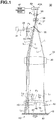
- a lens image sensing apparatus 30 includes a light source 31 placed on the side of the convex surface 1a of the test lens 1, and an optical device 32 which guides light beams L emitted by the light source 31 to the test lens 1.
- the light source 31 is used to irradiate the test lens 1 to obtain sharp images of the marks 3A, 3B, and 3C, the number 4 indicating the addition power, and the identification mark 5, and is a monochromatic point source.
- the monochromatic point source is a general term including a laser light source that is a point source, and a light source, such as an LED, that can be substantially regarded to be a point source. Note that this exemplifies a red semiconductor laser as the point source.
- the optical device 32 includes a condenser lens 33, transmission rotary scattering plate 34, half mirror 35, and collimator lens 36.
- the condenser lens 33 focuses the light beams L emitted by the light source 31.
- the transmission rotary scattering plate 34 is placed in front of the condenser lens 33.
- the half mirror 35 guides the light beams L transmitted through the transmission rotary scattering plate 34 toward the test lens 1.
- the collimator lens 36 is provided between the half mirror 35 and the test lens 1, and converts the light beams L from the light source 31 into collimated light beams L 1 .
- the transmission rotary scattering plate 34 is used to eliminate any speckles and fringes, and serves as a transparent scatterer made of, e.g., glass.
- the transmission rotary scattering plate 34 is configured to be rotated by a driving motor (not shown) at the time of measuring the marks on the test lens 1 so as to scatter the light beams L from the light source 31. For this reason, the transmission rotary scattering plate 34 has a coarse surface 34a facing the half mirror 35, and is placed at a focal position P 1 of the condenser lens 33.
- the half mirror 35 has an appropriate transmittance and reflectance: it reflects the light beams L, which are emitted by the light source 31 and transmitted through the condenser lens 33 and transmission rotary scattering plate 34, toward the test lens 1, and transmits light beams L 2 and L 3 which return from the side of the test lens 1.
- the collimator lens 36 is arranged in the optical path between the test lens 1 and the half mirror 35.
- the collimator lens 36 converts the light beams L, which are emitted by the light source 31, transmitted through the condenser lens 33 and transmission rotary scattering plate 34, and reflected by the half mirror 35, into the collimated light beams L 1 .
- test lens 1 is placed at a focal position P 2 of the collimator lens 36 on its lower side.
- An aperture stop 37, bandpass filter 38, re-imaging lens 39, image sensing device 40, and image processing device 41 are placed on the side of the half mirror 35 opposite to that of the test lens 1.
- the aperture stop 37 is placed at a focal position P 3 of the collimator lens 36 on its upper side, and limits the diameter of the light beam coming from the collimator lens 36. More specifically, the aperture stop 37 has a diameter which is smaller than that of a light beam from the mark 3C on the convex surface 1a of the test lens 1, and is larger than that of a light beam from a non-mark portion.
- the position of the aperture stop 37 is not limited to the focal position P 3 of the collimator lens 36. The same function can also be realized by placing the aperture stop 37 at the position of the exit pupil of the collimator lens 36.
- the bandpass filter 38 serves to transmit only light in the wavelength range of the light source 31 and cut off ambient light, and is provided between the aperture stop 37 and the re-imaging lens 39.
- the re-imaging lens 39 focuses the light beams L 2 and L 3 having passed through the bandpass filter 38 on the image sensing device 40.
- the image sensing device 40 includes a plurality of CCDs 40A which form a light-receiving surface, and is electrically connected to the image processing device 41.
- the CCDs 40A are placed at a focal position P 4 of the re-imaging lens 39.
- the focal position P 4 of the re-imaging lens 39 is conjugate to the position of the convex surface 1a of the test lens 1 on the side of the collimator lens 36.
- the lens image sensing apparatus 30 also includes a lens holding device 42 and rotary reflector 43 placed on the side of a concave surface 1b of the test lens 1.
- the lens holding device 42 serves to chuck and fix the center of the concave surface 1b of the test lens 1, and includes a transparent plate 45 and a lens chucking cylinder 46 standing upright at the center of the upper surface of the transparent plate 45.
- the lens holding device 42 is configured to chuck and fix the center of the concave surface 1b of the test lens 1 on the upper surface of the lens chucking cylinder 46 by evacuating the lens chucking cylinder 46 using a vacuum pump.
- the lens chucking cylinder 46 has an outer diameter (e.g., 8 mm) small enough not to hamper projection of the marks 3A, 3B, and 3C, the number 4 indicating the addition power, and the identification mark 5 on the test lens 1.
- the rotary reflector 43 serves to retroreflect the light beams L 1 . transmitted through the test lens 1 in the same directions as their incident directions, and includes a rotary plate 47 and a corner cube prism sheet 48 attached to the surface of the rotary plate 47.
- the corner cube prism sheet 48 is made of plastic with a thickness of about 0.3 mm to 0.5 mm, includes a plurality of corner cube prisms (to be also simply referred to as prisms hereinafter) 49 formed on its surface, and is protected by a transparent protective film over the entire surface.
- the prisms 49 themselves are conventionally known prisms, which have three orthogonal total reflecting surfaces to have a function of reflecting the collimated light beams L 1 transmitted through the test lens 1 in the same directions as their incident directions, i.e., a retroreflection function.
- the rotary reflector 43 is configured to be rotated at high speed (e.g., at 3,400 rpm) by a driving motor (not shown) in order to uniform its surface brightness and background, like the transmission rotary scattering plate 34.
- Fig. 1 shows only three light beams L scattered by the transmission rotary scattering plate 34. These scattered light beams L are reflected by the half mirror 35, are converted into two collimated light beams L 1 and one collimated light beam L 2 , irradiate the mark 3C and two non-mark portions on the test lens 1, are retroreflected by the prisms 49, and focus on the CCDs 40A of the image sensing device 40 as four light beams L 2 and L 3 .
- light beams which irradiate other different portions on the test lens 1 and are transmitted through them similarly focus on the CCDs 40A and form images on them, as a matter of course.
- test lens 1 is provided into the opening in the upper surface of the lens chucking cylinder 46 with the convex surface 1a facing up.
- a vacuum exhaust device evacuates the lens chucking cylinder 46 to chuck and fix the test lens 1 in the opening in the upper surface of the lens chucking cylinder 46.
- the light source 31 is turned on to emit light beams (red laser beams) L.
- the light beams L emitted by the light source 31 are focused by the condenser lens 33.
- the light beams L are converted into scattered light beams upon being transmitted through the transmission rotary scattering plate 34.
- the light beams L strike the half mirror 35, are reflected toward the test lens 1, and are further converted into collimated light beams L 1 upon being transmitted through the collimator lens 36.
- the collimated light beams L 1 become diverging light beams upon being transmitted through the test lens 1 from the convex surface 1a to the concave surface 1b (the collimated light beams L 1 become converging light beams when the test lens 1 is a convex converging dioptric lens).
- the collimated light beam L 1 which enters the test lens 1 from a lens surface portion (non-mark portion) other than that where the mark is inscribed strikes the prisms 49, is reflected by the prisms 49 in the same direction as its incident direction to the prisms 49.
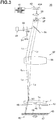
- the light beam L 2 is transmitted through the test lens 1 from the concave surface 1b, and returns to the convex surface 1a, as shown in Fig. 2 .
- a reflected light beam L 2 diffuses upon being transmitted through the test lens 1. Nevertheless, because the degree of diffusion of the light beam transmitted through the non-mark portion on the convex surface 1a is small enough to be ignored, the light beam L 2 becomes a retroreflected light beam with a sufficiently small diameter.
- the retroreflected light beam L 2 passes through the aperture stop 37 with little loss after being transmitted through the collimator lens 36 again.
- the retroreflected light beam L 2 having passed through the aperture stop 37 is transmitted through the bandpass filter 38 and re-imaging lens 39, and focused on the CCDs 40A of the image sensing device 40, thereby forming a bright image.
- the collimated light beam L 1 transmitted through the collimator lens 36 strikes and is retroreflected by the prisms 49 upon being transmitted through the test lens 1, and is transmitted through the test lens 1 again.
- the reflected light beam L 3 diffuses upon being transmitted through the mark 3C.
- the degree of diffusion of the reflected light beam L 3 is larger than the retroreflected light beam L 2 transmitted through the non-mark portion mentioned above.
- the light beam L 3 transmitted through the mark 3C becomes a diverging retroreflected light beam, returns in the same direction as its incident direction, is transmitted through the collimator lens 36, and passes through the aperture stop 37 with a considerable loss because its diameter is larger than that of the aperture stop 37.
- the diverging retroreflected light beam L 3 is focused on the CCDs 40A of the image sensing device 40 after being transmitted through the bandpass filter 38 and re-imaging lens 39. This makes it possible to sense a sharp image of the mark 3C because the illuminance of the mark 3C on the CCDs 40A is lower than the non-mark portion.
- the image sensing device 40 converts the light received by the CCDs 40A into an electrical signal, and sends it to the image processing device 41.
- the image processing device 41 processes the image information from the image sensing device 40 to identify a spectacle shop as the delivery destination using the mark 3C. Also, the image sensing device 40 receives the pieces of image information of, e.g., the marks 3A and 3B to calculate the positions of, e.g., the geometric center O and eyepoint 11 based on the pieces of position information of these marks 3A and 3B.
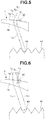
- Fig. 5 is a view showing the route of a light beam which is transmitted through only the non-mark portion and is not transmitted through the mark 3C.
- the test lens 1 is a minus-power lens and the prisms 49 have an appropriate size.
- the collimated light beam L 1 which enters the non-mark portion on the convex surface 1a of the test lens 1 on its periphery is transmitted through the test lens 1, becomes a diffused light beam, enters the corner cube prisms 49, and is totally reflected in the same direction as its incident direction by the prisms 49.
- the reflected light beam L 1 enters the concave surface 1b of the test lens 1, is transmitted through the test lens 1 again, and exits the non-mark portion on the convex surface 1a.
- An entrance point X 1 of the collimated light beam L 1 and an exit point X 2 of the light beam (retroreflected light beam) L 2 which is reflected by the prisms 49 and exits the convex surface 1a slightly shift from each other in the optical axis direction of the test lens 1.
- the light beam L 2 which enters and is reflected by the prisms 49 becomes a retroreflected light beam parallel to the collimated light beam L 1 , and travels back the way it came.
- the retroreflected light beam L 2 is transmitted through the collimator lens 36, half mirror 35, aperture stop 37, bandpass filter 38, and re-imaging lens 39 shown in Figs. 1 to 3 , and is focused on the CCDs 40A of the image sensing device 40, thereby forming a bright image.
- Fig. 6 is a view showing the route of a light beam transmitted through the mark 3C and the non-mark portion in this order. Because a periphery C of the mark 3C has a surface curvature quite different from that of the non-mark portion, the collimated light beam L 1 which enters and is transmitted through the periphery C becomes the light beam L 3 , enters the prisms 49, and is totally reflected in the same direction as its incident direction by the prisms 49. The light beam L 3 is transmitted through the non-mark portion on the test lens 1, exits the non-mark portion from an exit point X 3 , becomes a light beam parallel to the collimated light beam L 1 , and travels back the way it came.
- the light beam L 3 is diffused by the periphery C of the mark 3C and therefore becomes a diverging retroreflected light beam with a diameter larger than the retroreflected light beam L 2 which enters the non-mark portion and exits the non-mark portion, mentioned above.
- the diverging retroreflected light beam L 3 passes through the aperture stop 37 with a considerable loss, and has an illuminance on the CCDs 40A, that is lower than the non-mark portion, as described above.
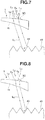
- Fig. 7 is a view for explaining the route of a light beam transmitted through the non-mark portion and the periphery of the mark 3C in this order.
- the collimated light beam L 1 which enters the non-mark portion on the convex surface 1a from a point X 4 near the mark 3C, and is transmitted through the non-mark portion enters the prisms 49, is totally reflected in the same direction as its incident direction by the prisms 49, and exits the periphery C of the mark 3C.
- the collimated light beam L 1 diffuses into a diverging retroreflected reflected light beam L 4 with a large diameter, and exits the convex surface 1a of the test lens 1.
- the diverging retroreflected reflected light beam L 4 passes through the aperture stop 37 with a considerable loss, and has an illuminance on the CCDs 40A, that is lower than the non-mark portion, as described above.
- Fig. 8 is a view showing the route of a light beam which enters the central portion of the mark 3C, and exits the non-mark portion from a point near the mark 3C.
- the collimated light beam L 1 which enters a central portion X 5 of the mark 3C, and is transmitted through the test lens 1 enters the prisms 49, is totally reflected in the same direction as its incident direction by the prisms 49, is transmitted through the non-mark portion on the test lens 1, and exits the non-mark portion from an exit point X 6 . Because the central portion of the periphery C has a surface curvature close to that of the non-mark portion, the degree of diffusion of the collimated light beam L 1 by the mark 3C is very small.
- the collimated light beam L 1 exits the convex surface 1a of the test lens 1 from the exit point X 6 as a retroreflected light beam L 5 with a small diameter.
- the retroreflected light beam L 5 is transmitted through the bandpass filter 38 and re-imaging lens 39, and focused on the CCDs 40A of the image sensing device 40 without any loss due to factors associated with the aperture stop 37, thereby forming a bright image, like the light beam L 2 shown in Figs. 2 and 5 .
- Fig. 9 is a view showing the route of a light beam which enters the non-mark portion from a point near the mark 3C, is transmitted through the non-mark portion, and exits the central portion of the mark 3C upon re-transmission.
- the collimated light beam L 1 which enters the non-mark portion on the test lens 1 from a point X 7 near the mark 3C, and is transmitted through the test lens 1 enters the prisms 49, and is totally reflected in the same direction as its incident direction by the prisms 49.
- a reflected light beam L 6 exits the central portion X 5 of the mark 3C.
- the reflected light beam L 6 is transmitted through the central portion X 5 of the mark 3C with little diffusion, and exits the convex surface 1a of the test lens 1 from the central portion X 5 as a retroreflected light beam with a small diameter.
- the reflected light beam L 6 is transmitted through the bandpass filter 38 and re-imaging lens 39, and focused on the CCDs 40A without any loss due to factors associated with the aperture stop 37, thereby forming a bright image, like the retroreflected light beams L 2 and L 5 .
- the light beams L 2 , L 5 , and L 6 transmitted through only the non-mark portion on the convex surface 1a in both the forward and backward paths are returned as retroreflected light beams with small degrees of diffusion, and focused on the light-receiving surface of the CCDs 40A.
- the light beams L 3 and L 4 transmitted through the periphery C of the mark 3C in at least one of the forward and backward paths are returned as diverging retroreflected light beams with large degrees of diffusion, and focused on the light-receiving surface of the CCDs 40A.
- the retroreflected light beams L 2 , L 5 , and L 6 and the diverging retroreflected light beams L 3 and L 4 are guided to the aperture stop 37, the retroreflected light beams L 2 , L 5 , and L 6 pass through the aperture stop 37 without any losses because they have sufficiently small diameters.
- the retroreflected light beams L 2 , L 5 , and L 6 can generate high illuminances of the mark on the light-receiving surface of the CCDs 40A.
- the diverging retroreflected light beams L 3 and L 4 have diameters larger than that of the aperture stop 37, so they generate low illuminances of the mark on the light-receiving surface of the CCDs 40A because their losses due to factors associated with the aperture stop 37 are large.
- the lens image sensing apparatus 30 can obtain a mark image which is sharper and has a higher contrast than that obtained using the above-mentioned conventional reflective screen. This makes it possible to facilitate image processing, and, in turn, facilitate design of an image processing circuit.
- Fig. 10 is a view showing an image of the mark 3C obtained by the apparatus.
- an image of the mark 3C formed on the CCDs 40A of the image sensing device 40 has a dark periphery, a bright central portion, and a clear contour shape, and these features facilitate image processing by the image processing device 41.
- the transmission rotary scattering plate 34 Since the transmission rotary scattering plate 34 is used, generation of any speckles due to factors associated with the laser light source can be suppressed and prevented. Also, since the brightness of the surface of the corner cube prism sheet 48 in the image background is equalized by the rotary reflector 43, image processing can further be facilitated.
- test lens 1 is a colored lens, it is possible to obtain a sharp image with high contrast as long as the mark has a shape which can obtain retroreflected light and diverging retroreflected light.
- the ratio between the focal length (f 1 ) of the collimator lens 36 and the focal length (f 2 ) of the re-imaging lens 39 becomes sufficiently high. This makes it possible to set the longitudinal magnification sufficiently high as well, thus increasing the depth of focus. This has the advantage of minimizing defocusing at the time of observing a thick lens, thus reducing the shadows of the end face of a minus-power lens.
- the light beams L emitted by the light source 31 are converted into the collimated light beams L 1 by the collimator lens 36.
- the exit light from the collimator lens 36 obliquely enters the end face of the test lens 1. Therefore, this incident light strikes and is reflected by the edge surface, does not become effective retroreflected light even when it is reflected by the prisms 49, and is not focused on the CCDs 40A of the image sensing device 40. This makes it impossible to obtain a sharp image.
- the exit light from the collimator lens 36 enters the end face of a minus-power lens at a large incident angle. Therefore, this incident light is refracted toward the lens center without striking the edge surface, becomes retroreflected light upon being reflected by the prisms 49 after its transmission through the lens, travels back the way it came, and is focused on the CCDs 40A. This makes it possible to obtain a sharp image.
- a conjugate optical system including the collimator lens 36 and re-imaging lens 39 is designed as a bilateral telecentric optical system, this is preferable because an image with the same barycentric position as an image free from defocusing can be obtained even if defocusing occurs upon fluctuation in thickness of the test lens 1.
- a concave mark is symmetrical to a convex mark and has, on the periphery of its concave portion, a surface curvature quite different from that of the convex surface 1a of the test lens 1, light transmitted through the periphery has a large degree of diffusion and therefore becomes diverging retroreflected light, whereas light transmitted through the central portion of the concave portion has a small degree of diffusion and therefore becomes retroreflected light. This makes it possible to obtain a mark image with a clear contour shape and high contrast between the retroreflected light and the diverging retroreflected light.
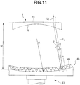
- Fig. 11 is a sectional view showing a corner cube prism sheet according to the embodiment of the present invention.
- a corner cube prism sheet 48 is concavely curved on the light source side instead of being formed in a flat shape.
- Other constituent components in this embodiment are quite the same as the ones shown in Fig. 1 .
- corner cube prism sheet 48 is formed in a flat shape, as indicated by an alternate long and two short dashed line.
- a light beam L 1 farther away from the center of a test lens 1 has a larger incident angle ⁇ on the surface of corner cube prisms 49.
- the corner cube prisms 49 exhibit low reflection efficiency. That is, a large light loss is generated, and this darkens the entire image. This means that a sharp image is hard to obtain when a mark is inscribed on the test lens 1 near its outer periphery.
- the corner cube prism sheet 48 is concavely curved when viewed from the light source side. Then, the light beam L 1 farther away from the center of the test lens 1 can have an incident angle ⁇ on the surface of the corner cube prisms 49, that is smaller than when the corner cube prism sheet 48 is flat. Thus, the corner cube prisms 49 exhibit high reflection efficiency, and this makes it possible to reduce a light loss. In this way, a sharp image can be obtained even when a mark inscribed on the test lens 1 near its outer periphery is used.
- the corner cube prism sheet 48 has too large a radius of curvature R, it has a shape close to that of a flat plate, and this lessens the effect produced by the corner cube prism sheet 48. If the corner cube prism sheet 48 has too small a radius of curvature R, a light beam which passes through the test lens 1 near its periphery enters the corner cube prism sheet 48 at a relatively large incident angle, and this generates a light loss.
- the corner cube prism sheet 48 is desirably designed to have a preferable value of the radius of curvature R in accordance with the lens dioptric power.
- the radius of curvature R can be set to a value obtained by adding a correction value that depends on the angle of divergence of the incident light beam to the radius of curvature R.
- the light source used is a monochromatic point source.
- the corner cube prism sheet is concavely curved when viewed from the light source side to reduce a light loss. That is, when the corner cube prism sheet is flat, light transmitted through the test lens at a position farther away from the center of the test lens more obliquely enters the corner cube prism. This generates a light loss due to factors associated with the prism geometrical structure, and lowers reflection efficiency (the intensity ratio between the incident beam and the outgoing beam). This phenomenon is undesirable because it generates a decrease in image luminance on the outer periphery of the test lens, which exhibits especially high divergence, and deteriorates the detection sensitivity of a mark located near the outer periphery.
- the corner cube prism sheet is concavely curved when viewed from the light source side.
- a light beam which passes through a diverging test lens at a position farther away from its center can have an incident angle on the corner cube prisms, that is smaller than when a flat sheet is used. This makes it possible to keep a light loss small enough to be ignored, and, in turn, makes it possible to sense a sharp image of even a mark inscribed on the test lens near its outer periphery.
- a converging test lens shows a decrease in luminance on its outer periphery less conspicuous than a diverging test lens.
- the former lens has a converging optical path from the test lens to the corner cube prism sheet.
- corner cube prism sheet is undesirably convexly curved when viewed from the light source side, a light beam transmitted through the outer periphery of a diverging test lens enters the corner cube prisms at a large incident angle, and this generates a large light loss and lowers reflection efficiency. This makes it impossible to sense a sharp image of the mark.
- the optical device includes a condenser lens, transmission rotary scattering plate, and half mirror.
- the condenser lens focuses light emitted by the light source.
- the transmission rotary scattering plate scatters the light transmitted through the condenser lens.
- the half mirror guides the light transmitted through the transmission rotary scattering plate to the collimator lens, and further guides, to the aperture stop, the light which is transmitted through the test lens, strikes and is reflected by the rotary reflector, is transmitted through the test lens and collimator lens again, and returns.
- the image sensing device includes a bandpass filter which transmits only light in the wavelength range of the light from the light source.
- the bandpass filter transmits only light in the wavelength range of the light from the light source, it is possible to sense an image with high contrast with little influence of ambient light.
- the image sensing device includes an image processing device which processes the image sensed by the image sensing device.
Landscapes
- Physics & Mathematics (AREA)
- General Physics & Mathematics (AREA)
- Chemical & Material Sciences (AREA)
- Analytical Chemistry (AREA)
- Life Sciences & Earth Sciences (AREA)
- Health & Medical Sciences (AREA)
- Geometry (AREA)
- Biochemistry (AREA)
- General Health & Medical Sciences (AREA)
- Immunology (AREA)
- Pathology (AREA)
- Testing Of Optical Devices Or Fibers (AREA)
- Investigating Materials By The Use Of Optical Means Adapted For Particular Applications (AREA)
Claims (5)
- Appareil de détection d'image de lentille (30) comprenant :une source lumineuse (31) ;un dispositif optique (32) comprenant une lentille de collimation qui est configurée pour convertir une lumière émise par ladite source lumineuse (31) en lumière collimatée, et pour guider la lumière collimatée jusqu'à une surface convexe d'une lentille de test ;un réflecteur rotatif (43) configuré pour réfléchir la lumière transmise par l'intermédiaire de la lentille de test jusqu'à la lentille de test ;un dispositif de détection d'image (40) configuré pour recevoir la lumière qui est réfléchie par ledit réflecteur rotatif (43) et transmise par l'intermédiaire de la lentille de test et de ladite lentille de collimation ;une butée d'ouverture (37) agencée dans une voie optique entre ladite lentille de collimation et ledit dispositif de détection d'image (40) ; etune lentille de re-imagerie (39) prévue entre ladite butée d'ouverture (37) et ledit dispositif de détection d'image (40),ledit réflecteur rotatif (43) comprenant une feuille formée à partir d'une pluralité de prismes de cube de coin,caractérisé en ce que ladite feuille est incurvée de manière concave dans une vue depuis un côté de ladite source lumineuse (31).
- Appareil de détection d'image de lentille (30) selon la revendication 1, dans lequel ladite source lumineuse (31) comprend une source de point monochromatique.
- Appareil de détection d'image de lentille (30) selon la revendication 1, dans lequel ledit dispositif optique (32) comprend en outre une lentille de condensation qui focalise une lumière émise par ladite source lumineuse (31), une plaque de diffusion rotative de transmission qui diffuse la lumière transmise par l'intermédiaire de ladite lentille de condensation, et un demi-miroir qui guide la lumière transmise par l'intermédiaire de ladite plaque de diffusion rotative de transmission jusqu'à ladite lentille de collimation, et qui guide, jusqu'à ladite butée d'ouverture (37), la lumière qui est transmise par l'intermédiaire de la lentille de test et de ladite lentille de collimation à nouveau et qui retourne.
- Appareil de détection d'image de lentille (30) selon la revendication 1, dans lequel ledit dispositif de détection d'image (40) comprend un filtre passe-bande qui transmet uniquement une lumière dans une plage de longueurs d'onde de la lumière provenant de ladite source lumineuse (31).
- Appareil de détection d'image de lentille (30) selon la revendication 1, comprenant en outre un dispositif de traitement d'image qui traite l'image détectée par ledit dispositif de détection d'image (40).
Applications Claiming Priority (2)
| Application Number | Priority Date | Filing Date | Title |
|---|---|---|---|
| JP2007334895A JP4906708B2 (ja) | 2007-12-26 | 2007-12-26 | レンズ用画像撮像装置 |
| PCT/JP2008/073398 WO2009081928A1 (fr) | 2007-12-26 | 2008-12-24 | Dispositif de capture d'image pour lentille |
Publications (3)
| Publication Number | Publication Date |
|---|---|
| EP2239552A1 EP2239552A1 (fr) | 2010-10-13 |
| EP2239552A4 EP2239552A4 (fr) | 2015-07-08 |
| EP2239552B1 true EP2239552B1 (fr) | 2018-09-19 |
Family
ID=40801228
Family Applications (1)
| Application Number | Title | Priority Date | Filing Date |
|---|---|---|---|
| EP08865745.7A Not-in-force EP2239552B1 (fr) | 2007-12-26 | 2008-12-24 | Dispositif de capture d'image pour lentille |
Country Status (4)
| Country | Link |
|---|---|
| US (1) | US20100283999A1 (fr) |
| EP (1) | EP2239552B1 (fr) |
| JP (1) | JP4906708B2 (fr) |
| WO (1) | WO2009081928A1 (fr) |
Families Citing this family (18)
| Publication number | Priority date | Publication date | Assignee | Title |
|---|---|---|---|---|
| US10259607B2 (en) * | 2008-03-04 | 2019-04-16 | Vanrx Pharmasystems Inc. | Aseptic robotic filling system and method |
| US20130242083A1 (en) * | 2010-10-08 | 2013-09-19 | Timothy A. Potts | Retro-reflective imaging |
| JP5708451B2 (ja) * | 2011-11-14 | 2015-04-30 | 株式会社島津製作所 | 試料支持治具 |
| US10976572B2 (en) | 2011-12-22 | 2021-04-13 | Carl Zeiss Vision International Gmbh | Method for storing information on a spectacles lens, spectacles lens blank or spectacles lens semi-finished product |
| DE102011089704B4 (de) * | 2011-12-22 | 2020-06-18 | Carl Zeiss Vision International Gmbh | Verfahren zum Speichern von Information auf einem Brillenglas, als Brillenglas-Rohling oder Brillenglas-Halbfabrikat ausgebildeter Glas- oder Kunststoffkörper, Vorrichtung für das Speichern von Information, Verfahren zum Auslesen sowie Lesegerät |
| FR3017964B1 (fr) * | 2014-02-27 | 2016-03-25 | Essilor Int | Instrument optique pour reperer au moins un point caracteristique d'une lentille ophtalmique |
| FR3017963B1 (fr) * | 2014-02-27 | 2016-03-25 | Essilor Int | Instrument optique pour identifier et localiser des microgravures presentes sur une lentille ophtalmique |
| CN104931238B (zh) * | 2015-05-18 | 2018-03-30 | 京东方科技集团股份有限公司 | 一种测试透明显示基板透明效果的设备及方法 |
| DE102015115735B3 (de) * | 2015-09-17 | 2017-03-23 | Carl Zeiss Vision International Gmbh | Vorrichtung und Verfahren zum Sichtbarmachen eines Signierzeichens auf einem Brillenglas |
| EP3388813B1 (fr) * | 2017-04-13 | 2021-09-29 | Carl Zeiss Vision International GmbH | Procédé de fabrication d'un verre de lunette selon au moins un ensemble de données relatives au bord du moule |
| CN110146257B (zh) * | 2019-05-17 | 2024-02-20 | 中国科学院上海技术物理研究所 | 一种快速测量空间激光载荷光轴变化的装置及方法 |
| CN113484322B (zh) * | 2021-07-13 | 2023-01-10 | 天津大学 | 可实时反馈轴向光阱位置的光镊超分辨成像方法和系统 |
| CN114139562B (zh) * | 2021-12-08 | 2025-07-01 | 深圳思谋信息科技有限公司 | 二维码检测装置 |
| CN116086776B (zh) * | 2023-01-19 | 2026-02-17 | 南京理工大学 | 一种准直光束发散角检测装置及发散角检测方法 |
| KR20240127754A (ko) * | 2023-02-16 | 2024-08-23 | 삼성전자주식회사 | 광학 계측 설비 |
| CN118624183B (zh) * | 2024-08-09 | 2024-11-12 | 厦门捷能通光电科技有限公司 | 一种灯珠用透镜光损检测装置及方法 |
| EP4726373A1 (fr) * | 2024-10-10 | 2026-04-15 | Carl Zeiss Jena GmbH | Procédé d'inspection, procédé de fabrication et système d'inspection |
| KR102928061B1 (ko) | 2025-07-16 | 2026-02-19 | (주) 캔랩 | 렌즈 결함 검사 시스템 및 방법 |
Family Cites Families (19)
| Publication number | Priority date | Publication date | Assignee | Title |
|---|---|---|---|---|
| US3375754A (en) * | 1964-09-29 | 1968-04-02 | Bausch & Lomb | Lens testing autocollimator |
| JPS604401B2 (ja) * | 1975-01-21 | 1985-02-04 | コニカ株式会社 | 干渉装置 |
| JP3404134B2 (ja) * | 1994-06-21 | 2003-05-06 | 株式会社ニュークリエイション | 検査装置 |
| JP3886619B2 (ja) * | 1997-10-16 | 2007-02-28 | 住友化学株式会社 | 物体の欠陥の検査方法および検査装置 |
| US5923425A (en) * | 1997-11-20 | 1999-07-13 | Tropel Corporation | Grazing incidence interferometry for measuring transparent plane-parallel plates |
| DE29901791U1 (de) * | 1999-02-02 | 2000-07-06 | Novartis Ag, Basel | Linsenmesseinrichtung |
| DE19942998B4 (de) * | 1999-09-09 | 2012-02-09 | Carl Zeiss Jena Gmbh | Mikroskop zur Auf- und Durchlichtmikroskopie |
| JP2002162655A (ja) * | 2000-11-27 | 2002-06-07 | Sony Corp | 光学装置 |
| CA2413343A1 (fr) * | 2002-12-02 | 2004-06-02 | Peter Vokhmin | Methode et appareil de verification de composants optiques |
| FR2853734B1 (fr) * | 2003-04-14 | 2005-05-27 | Tecoptique | Systeme de visualisation de marquages optiques d'un verre ophtalmique, dispositif de tamponnage et procede d'orientation de verres utilisant un tel systeme |
| DE10333426B4 (de) * | 2003-07-17 | 2006-02-09 | Carl Zeiss | Verfahren und Vorrichtung zum Sichtbarmachen eines Signierzeichens auf einem Brillenglas |
| WO2005096074A1 (fr) * | 2004-03-31 | 2005-10-13 | Kabushiki Kaisha Topcon | Dispositif de montage |
| EP1736816B1 (fr) * | 2004-03-31 | 2012-06-13 | Topcon Corporation | Dispositif permettant d'installer un cadre à aspiration pour verres de lunettes et méthode pour déterminer la position d'installation du cadre à aspiration |
| JP4514036B2 (ja) * | 2004-10-20 | 2010-07-28 | Hoya株式会社 | レンズ用撮像装置 |
| JP4761289B2 (ja) * | 2004-11-22 | 2011-08-31 | Hoya株式会社 | マーキング装置及びマーキング方法 |
| JP4409467B2 (ja) * | 2005-02-08 | 2010-02-03 | 株式会社トプコン | 眼鏡レンズの吸着治具取付装置 |
| JP4822318B2 (ja) * | 2005-10-18 | 2011-11-24 | 株式会社トプコン | レンズ吸着治具装着装置に用いられるレンズの位置特定方法およびレンズ吸着治具装着装置 |
| JP2007252402A (ja) * | 2006-03-20 | 2007-10-04 | Topcon Corp | 眼科測定装置 |
| JP4970149B2 (ja) * | 2007-05-31 | 2012-07-04 | 株式会社ニデック | カップ取付け装置 |
-
2007
- 2007-12-26 JP JP2007334895A patent/JP4906708B2/ja not_active Expired - Fee Related
-
2008
- 2008-12-24 WO PCT/JP2008/073398 patent/WO2009081928A1/fr not_active Ceased
- 2008-12-24 US US12/810,144 patent/US20100283999A1/en not_active Abandoned
- 2008-12-24 EP EP08865745.7A patent/EP2239552B1/fr not_active Not-in-force
Non-Patent Citations (1)
| Title |
|---|
| None * |
Also Published As
| Publication number | Publication date |
|---|---|
| EP2239552A4 (fr) | 2015-07-08 |
| US20100283999A1 (en) | 2010-11-11 |
| JP2009156702A (ja) | 2009-07-16 |
| JP4906708B2 (ja) | 2012-03-28 |
| EP2239552A1 (fr) | 2010-10-13 |
| WO2009081928A1 (fr) | 2009-07-02 |
Similar Documents
| Publication | Publication Date | Title |
|---|---|---|
| EP2239552B1 (fr) | Dispositif de capture d'image pour lentille | |
| US20110317156A1 (en) | Inspection device for defect inspection | |
| US20040004727A1 (en) | Three-dimensional shape measuring method, and three-dimensional shape measuring apparatus | |
| JPH10501890A (ja) | 反射性目標マークの位置を決定する光学装置 | |
| JP3617805B2 (ja) | 眼鏡レンズ用画像撮像処理装置 | |
| EP1035408A1 (fr) | Appareil de mesure des caracteristiques d'un angle optique | |
| US7796276B2 (en) | Apparatus and method for examining a curved surface | |
| JP3221733B2 (ja) | レンズ測定装置 | |
| JPH06100723B2 (ja) | 反射照明装置 | |
| JPH0743110A (ja) | 二段検出式非接触位置決め装置 | |
| JP3417736B2 (ja) | 光学部材検査装置 | |
| JPH08254650A (ja) | 焦点検出装置 | |
| JP3388285B2 (ja) | 検査装置 | |
| JP2677351B2 (ja) | 立体状被検体外面検査装置 | |
| JPH08166514A (ja) | 斜光照明装置 | |
| KR101555542B1 (ko) | 평판패널 검사장치 | |
| JP2025508505A (ja) | 光学レンズ表面を測定する方法 | |
| JP4487042B2 (ja) | 光学装置、検査装置及び検査方法 | |
| JP4514036B2 (ja) | レンズ用撮像装置 | |
| KR101517097B1 (ko) | 평판패널 검사장치 | |
| KR100636505B1 (ko) | Line CCD를 이용하여 패턴을 검사하는 광학계용 조명장치 | |
| JP2000295639A (ja) | 固体撮像素子検査用照明装置及びそれに用いる調整工具 | |
| CN211263958U (zh) | 高灵敏度透明物体脉理和表面缺陷观测装置 | |
| EP1139090A2 (fr) | Appareil d'inspection de circuits integrés avec fils de connexion | |
| JP3040131B2 (ja) | 球体表面の傷検査装置 |
Legal Events
| Date | Code | Title | Description |
|---|---|---|---|
| PUAI | Public reference made under article 153(3) epc to a published international application that has entered the european phase |
Free format text: ORIGINAL CODE: 0009012 |
|
| 17P | Request for examination filed |
Effective date: 20100726 |
|
| AK | Designated contracting states |
Kind code of ref document: A1 Designated state(s): AT BE BG CH CY CZ DE DK EE ES FI FR GB GR HR HU IE IS IT LI LT LU LV MC MT NL NO PL PT RO SE SI SK TR |
|
| AX | Request for extension of the european patent |
Extension state: AL BA MK RS |
|
| DAX | Request for extension of the european patent (deleted) | ||
| REG | Reference to a national code |
Ref country code: DE Ref legal event code: R079 Ref document number: 602008057099 Country of ref document: DE Free format text: PREVIOUS MAIN CLASS: G01M0011000000 Ipc: G01M0011020000 |
|
| RA4 | Supplementary search report drawn up and despatched (corrected) |
Effective date: 20150609 |
|
| RIC1 | Information provided on ipc code assigned before grant |
Ipc: G01N 21/95 20060101ALI20150602BHEP Ipc: G01M 11/02 20060101AFI20150602BHEP Ipc: G01N 21/958 20060101ALI20150602BHEP |
|
| GRAP | Despatch of communication of intention to grant a patent |
Free format text: ORIGINAL CODE: EPIDOSNIGR1 |
|
| INTG | Intention to grant announced |
Effective date: 20180420 |
|
| GRAS | Grant fee paid |
Free format text: ORIGINAL CODE: EPIDOSNIGR3 |
|
| GRAA | (expected) grant |
Free format text: ORIGINAL CODE: 0009210 |
|
| AK | Designated contracting states |
Kind code of ref document: B1 Designated state(s): AT BE BG CH CY CZ DE DK EE ES FI FR GB GR HR HU IE IS IT LI LT LU LV MC MT NL NO PL PT RO SE SI SK TR |
|
| REG | Reference to a national code |
Ref country code: GB Ref legal event code: FG4D |
|
| REG | Reference to a national code |
Ref country code: CH Ref legal event code: EP |
|
| REG | Reference to a national code |
Ref country code: DE Ref legal event code: R096 Ref document number: 602008057099 Country of ref document: DE |
|
| REG | Reference to a national code |
Ref country code: AT Ref legal event code: REF Ref document number: 1043808 Country of ref document: AT Kind code of ref document: T Effective date: 20181015 |
|
| REG | Reference to a national code |
Ref country code: IE Ref legal event code: FG4D |
|
| REG | Reference to a national code |
Ref country code: NL Ref legal event code: MP Effective date: 20180919 |
|
| PG25 | Lapsed in a contracting state [announced via postgrant information from national office to epo] |
Ref country code: GR Free format text: LAPSE BECAUSE OF FAILURE TO SUBMIT A TRANSLATION OF THE DESCRIPTION OR TO PAY THE FEE WITHIN THE PRESCRIBED TIME-LIMIT Effective date: 20181220 Ref country code: FI Free format text: LAPSE BECAUSE OF FAILURE TO SUBMIT A TRANSLATION OF THE DESCRIPTION OR TO PAY THE FEE WITHIN THE PRESCRIBED TIME-LIMIT Effective date: 20180919 Ref country code: SE Free format text: LAPSE BECAUSE OF FAILURE TO SUBMIT A TRANSLATION OF THE DESCRIPTION OR TO PAY THE FEE WITHIN THE PRESCRIBED TIME-LIMIT Effective date: 20180919 Ref country code: NO Free format text: LAPSE BECAUSE OF FAILURE TO SUBMIT A TRANSLATION OF THE DESCRIPTION OR TO PAY THE FEE WITHIN THE PRESCRIBED TIME-LIMIT Effective date: 20181219 Ref country code: BG Free format text: LAPSE BECAUSE OF FAILURE TO SUBMIT A TRANSLATION OF THE DESCRIPTION OR TO PAY THE FEE WITHIN THE PRESCRIBED TIME-LIMIT Effective date: 20181219 Ref country code: LT Free format text: LAPSE BECAUSE OF FAILURE TO SUBMIT A TRANSLATION OF THE DESCRIPTION OR TO PAY THE FEE WITHIN THE PRESCRIBED TIME-LIMIT Effective date: 20180919 |
|
| REG | Reference to a national code |
Ref country code: LT Ref legal event code: MG4D |
|
| PG25 | Lapsed in a contracting state [announced via postgrant information from national office to epo] |
Ref country code: LV Free format text: LAPSE BECAUSE OF FAILURE TO SUBMIT A TRANSLATION OF THE DESCRIPTION OR TO PAY THE FEE WITHIN THE PRESCRIBED TIME-LIMIT Effective date: 20180919 Ref country code: HR Free format text: LAPSE BECAUSE OF FAILURE TO SUBMIT A TRANSLATION OF THE DESCRIPTION OR TO PAY THE FEE WITHIN THE PRESCRIBED TIME-LIMIT Effective date: 20180919 |
|
| REG | Reference to a national code |
Ref country code: AT Ref legal event code: MK05 Ref document number: 1043808 Country of ref document: AT Kind code of ref document: T Effective date: 20180919 |
|
| PG25 | Lapsed in a contracting state [announced via postgrant information from national office to epo] |
Ref country code: ES Free format text: LAPSE BECAUSE OF FAILURE TO SUBMIT A TRANSLATION OF THE DESCRIPTION OR TO PAY THE FEE WITHIN THE PRESCRIBED TIME-LIMIT Effective date: 20180919 Ref country code: IS Free format text: LAPSE BECAUSE OF FAILURE TO SUBMIT A TRANSLATION OF THE DESCRIPTION OR TO PAY THE FEE WITHIN THE PRESCRIBED TIME-LIMIT Effective date: 20190119 Ref country code: PL Free format text: LAPSE BECAUSE OF FAILURE TO SUBMIT A TRANSLATION OF THE DESCRIPTION OR TO PAY THE FEE WITHIN THE PRESCRIBED TIME-LIMIT Effective date: 20180919 Ref country code: IT Free format text: LAPSE BECAUSE OF FAILURE TO SUBMIT A TRANSLATION OF THE DESCRIPTION OR TO PAY THE FEE WITHIN THE PRESCRIBED TIME-LIMIT Effective date: 20180919 Ref country code: CZ Free format text: LAPSE BECAUSE OF FAILURE TO SUBMIT A TRANSLATION OF THE DESCRIPTION OR TO PAY THE FEE WITHIN THE PRESCRIBED TIME-LIMIT Effective date: 20180919 Ref country code: NL Free format text: LAPSE BECAUSE OF FAILURE TO SUBMIT A TRANSLATION OF THE DESCRIPTION OR TO PAY THE FEE WITHIN THE PRESCRIBED TIME-LIMIT Effective date: 20180919 Ref country code: EE Free format text: LAPSE BECAUSE OF FAILURE TO SUBMIT A TRANSLATION OF THE DESCRIPTION OR TO PAY THE FEE WITHIN THE PRESCRIBED TIME-LIMIT Effective date: 20180919 Ref country code: AT Free format text: LAPSE BECAUSE OF FAILURE TO SUBMIT A TRANSLATION OF THE DESCRIPTION OR TO PAY THE FEE WITHIN THE PRESCRIBED TIME-LIMIT Effective date: 20180919 Ref country code: RO Free format text: LAPSE BECAUSE OF FAILURE TO SUBMIT A TRANSLATION OF THE DESCRIPTION OR TO PAY THE FEE WITHIN THE PRESCRIBED TIME-LIMIT Effective date: 20180919 |
|
| PG25 | Lapsed in a contracting state [announced via postgrant information from national office to epo] |
Ref country code: PT Free format text: LAPSE BECAUSE OF FAILURE TO SUBMIT A TRANSLATION OF THE DESCRIPTION OR TO PAY THE FEE WITHIN THE PRESCRIBED TIME-LIMIT Effective date: 20190119 Ref country code: SK Free format text: LAPSE BECAUSE OF FAILURE TO SUBMIT A TRANSLATION OF THE DESCRIPTION OR TO PAY THE FEE WITHIN THE PRESCRIBED TIME-LIMIT Effective date: 20180919 |
|
| REG | Reference to a national code |
Ref country code: DE Ref legal event code: R097 Ref document number: 602008057099 Country of ref document: DE |
|
| REG | Reference to a national code |
Ref country code: DE Ref legal event code: R119 Ref document number: 602008057099 Country of ref document: DE |
|
| PLBE | No opposition filed within time limit |
Free format text: ORIGINAL CODE: 0009261 |
|
| STAA | Information on the status of an ep patent application or granted ep patent |
Free format text: STATUS: NO OPPOSITION FILED WITHIN TIME LIMIT |
|
| PG25 | Lapsed in a contracting state [announced via postgrant information from national office to epo] |
Ref country code: DK Free format text: LAPSE BECAUSE OF FAILURE TO SUBMIT A TRANSLATION OF THE DESCRIPTION OR TO PAY THE FEE WITHIN THE PRESCRIBED TIME-LIMIT Effective date: 20180919 |
|
| REG | Reference to a national code |
Ref country code: CH Ref legal event code: PL |
|
| 26N | No opposition filed |
Effective date: 20190620 |
|
| GBPC | Gb: european patent ceased through non-payment of renewal fee |
Effective date: 20181224 |
|
| PG25 | Lapsed in a contracting state [announced via postgrant information from national office to epo] |
Ref country code: LU Free format text: LAPSE BECAUSE OF NON-PAYMENT OF DUE FEES Effective date: 20181224 Ref country code: MC Free format text: LAPSE BECAUSE OF FAILURE TO SUBMIT A TRANSLATION OF THE DESCRIPTION OR TO PAY THE FEE WITHIN THE PRESCRIBED TIME-LIMIT Effective date: 20180919 |
|
| REG | Reference to a national code |
Ref country code: IE Ref legal event code: MM4A |
|
| REG | Reference to a national code |
Ref country code: BE Ref legal event code: MM Effective date: 20181231 |
|
| PG25 | Lapsed in a contracting state [announced via postgrant information from national office to epo] |
Ref country code: FR Free format text: LAPSE BECAUSE OF NON-PAYMENT OF DUE FEES Effective date: 20181231 Ref country code: IE Free format text: LAPSE BECAUSE OF NON-PAYMENT OF DUE FEES Effective date: 20181224 Ref country code: SI Free format text: LAPSE BECAUSE OF FAILURE TO SUBMIT A TRANSLATION OF THE DESCRIPTION OR TO PAY THE FEE WITHIN THE PRESCRIBED TIME-LIMIT Effective date: 20180919 Ref country code: DE Free format text: LAPSE BECAUSE OF NON-PAYMENT OF DUE FEES Effective date: 20190702 |
|
| PG25 | Lapsed in a contracting state [announced via postgrant information from national office to epo] |
Ref country code: BE Free format text: LAPSE BECAUSE OF NON-PAYMENT OF DUE FEES Effective date: 20181231 |
|
| PG25 | Lapsed in a contracting state [announced via postgrant information from national office to epo] |
Ref country code: LI Free format text: LAPSE BECAUSE OF NON-PAYMENT OF DUE FEES Effective date: 20181231 Ref country code: GB Free format text: LAPSE BECAUSE OF NON-PAYMENT OF DUE FEES Effective date: 20181224 Ref country code: CH Free format text: LAPSE BECAUSE OF NON-PAYMENT OF DUE FEES Effective date: 20181231 |
|
| PG25 | Lapsed in a contracting state [announced via postgrant information from national office to epo] |
Ref country code: MT Free format text: LAPSE BECAUSE OF NON-PAYMENT OF DUE FEES Effective date: 20181224 |
|
| PG25 | Lapsed in a contracting state [announced via postgrant information from national office to epo] |
Ref country code: TR Free format text: LAPSE BECAUSE OF FAILURE TO SUBMIT A TRANSLATION OF THE DESCRIPTION OR TO PAY THE FEE WITHIN THE PRESCRIBED TIME-LIMIT Effective date: 20180919 |
|
| PG25 | Lapsed in a contracting state [announced via postgrant information from national office to epo] |
Ref country code: HU Free format text: LAPSE BECAUSE OF FAILURE TO SUBMIT A TRANSLATION OF THE DESCRIPTION OR TO PAY THE FEE WITHIN THE PRESCRIBED TIME-LIMIT; INVALID AB INITIO Effective date: 20081224 Ref country code: CY Free format text: LAPSE BECAUSE OF FAILURE TO SUBMIT A TRANSLATION OF THE DESCRIPTION OR TO PAY THE FEE WITHIN THE PRESCRIBED TIME-LIMIT Effective date: 20180919 |