EP1139090A2 - Appareil d'inspection de circuits integrés avec fils de connexion - Google Patents
Appareil d'inspection de circuits integrés avec fils de connexion Download PDFInfo
- Publication number
- EP1139090A2 EP1139090A2 EP01108209A EP01108209A EP1139090A2 EP 1139090 A2 EP1139090 A2 EP 1139090A2 EP 01108209 A EP01108209 A EP 01108209A EP 01108209 A EP01108209 A EP 01108209A EP 1139090 A2 EP1139090 A2 EP 1139090A2
- Authority
- EP
- European Patent Office
- Prior art keywords
- optical
- datum
- aperture
- projection
- contour
- Prior art date
- Legal status (The legal status is an assumption and is not a legal conclusion. Google has not performed a legal analysis and makes no representation as to the accuracy of the status listed.)
- Withdrawn
Links
Images


Classifications
-
- G—PHYSICS
- G01—MEASURING; TESTING
- G01N—INVESTIGATING OR ANALYSING MATERIALS BY DETERMINING THEIR CHEMICAL OR PHYSICAL PROPERTIES
- G01N21/00—Investigating or analysing materials by the use of optical means, i.e. using sub-millimetre waves, infrared, visible or ultraviolet light
- G01N21/84—Systems specially adapted for particular applications
- G01N21/88—Investigating the presence of flaws or contamination
- G01N21/95—Investigating the presence of flaws or contamination characterised by the material or shape of the object to be examined
- G01N21/956—Inspecting patterns on the surface of objects
Definitions
- the invention relates to an apparatus for inspecting a leaded integrated circuit.
- U.S. patent No. 5,909,285 a method for inspection of integrated circuits is disclosed which includes a camera to image a precision pattern mask deposited on a transparent reticle to be inspected.
- the integrated circuit to be inspected is illuminated using diffused light.
- a side view of the integrated circuit is reflected to the camera by using an overhead mirror or prism.
- this method uses front lighting and further requires the integrated circuit to be exactly positioned on the transparent reticle.
- U.S. patent No. 5,910,844 a vision inspection system is known in which eight optical images are instantaneously recorded on singular image frames which are output from two optical cameras.
- the inspection system according to U.S. patent 5,910,844 requires complex optical reflecting means using a plurality of optical directing members.
- the optical directing members have to be selectively adjusted when objects of various sizes are inspected.
- an optical inspection system for determining positional information of an object with respect to a reference is known.
- a datum which is used as a reference of the system, is placed in proximity to the object to be inspected.
- a diffuse light source is provided for illuminating the object. The light source is set up such that a point on the object and a point on the datum will lie in the same plane as their images along at least two optical paths that form an angle with one another.
- an imaging subsystem is provided which captures images along the two optical paths. The captured images are correlated and analyzed by the imaging subsystem in order to provide positional information of the point on the object with respect to the point on the datum.
- patent application 09/205,852 it is possible to form the two optical paths which are relayed on the imaging subsystem by using a trapezoidal prism for one optical path and a mirror for the other optical path. Further, it is also possible to use one single trapezoidal prism for providing the two optical paths. In this way, one optical path is formed along an internal surface of the trapezoidal prism and the other optical path is formed along an external surface of the trapezoidal prism.
- the two optical paths differ in optical length such that the image quality and thus the precision of the inspection system suffers.
- a large sensor area is required in the optical subsystem for capturing the images resulting from the two optical paths due to a large blank area existing in the central portion of the image produced by the inspection system.
- the invention provides an inspection system for inspection of objects in form of leaded integrated circuits.
- a system according to the invention comprises a datum with an aperture therein defined by reference edges, the datum providing a reference plane which is at least substantially perpendicular to the optical axis of the system, wherein the object to be inspected is to be positioned e.g. by an object carrier in overlapping relationship with the aperture of the datum, a diffuse light source for radiating diffuse light through the aperture thereby projecting a lead-including contour of the object and a contour of the reference edge through the aperture in several projection directions, an optical prism for receiving the projections of the contours and for selecting two of the projections received from different projection directions.
- the optical prism comprises an external reflection surface for reflecting one of the two selected projections of the contours into a reflection direction towards an imaging plane. Further, the optical prism comprises an entrance surface, an exit surface and an internal reflection surface cooperating with the entrance surface and the exit surface for internal reflection of the other one of the two selected projections of the contours through the exit surface of the optical prism in an exit direction toward the imaging plane in such a way that a first projection path between the contour and the imaging plane for light rays of the one selected projection and a second projection path between the contour and the imaging plane of light rays for the other selected projection have the same optical length
- the present invention it is possible to arrange two or more optical prisms in order to measure or inspect for example two sides of a dual-sided integrated circuit. Thereby, the first side and the second side of the dual-sided integrated circuit are inspected simultaneously.
- rhomboid prisms are provided which effect redirection of the first projection path and of the second projection path in parallel to and close to the optical axis of the system.
- the image area for the dual-side inspection is therefore reduced, leading to an improvement of the effective image resolution and thus to improved measurement accuracy.
- the images produced by the inspection system are preferably captured by a video camera and are then digitized and processed by a processor of a computer in order to determine the 3-D coordinates of the objects with respect to the datum.
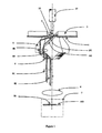
- FIG. 1 An inspection system for inspection of an object in the form of a leaded integrated circuit according to one preferred embodiment of the invention is illustrated in Figure 1 and comprises: a datum 1 with an aperture 2 therein defined by a reference edge 12, the datum 1 providing a reference plane which is perpendicular to the optical axis of the system, an object carrier 30 for positioning the object 10 in overlapping relationship with the aperture 2 of the datum 1, a diffuse light source 3 for radiating diffuse light through the aperture 2 thereby projecting a lead-including contour of the object 10 and a contour of the reference edge 12 through the aperture 2 in several projection directions, an optical prism 5 for receiving the projections of the contours and for selecting two of the projections received from different projection directions, the optical prism 5 having an external reflection surface 51 for reflecting one of the two selected projections of the contours into a reflection direction towards an imaging plane, and having an entrance surface, an exit surface and an internal reflection surface 52 cooperating with the entrance surface and the exit surface for internal reflection of the other one of the two selected projections of the contours through
- the lighting 3 is preferably arranged on top of the datum 1, but can also be arranged over the datum.
- An object 10 is held and positioned in the neighborhood of and overlapping the aperture 2 by an object carrier 30 which preferably has a vacuum tip in order to hold the object 10 from above.
- the object 10 can be an integrated circuit having a plurality of pins or leads.
- Two optical prisms 5 are arranged at the bottom of the datum, one for inspecting each side of the object 10.
- Two rhomboid prisms 8 are arranged below the the optical prisms 5 and are directed towards the optical axis of the inspection system.
- a lens 6 attached to a video camera 7 is arranged in alignment with the optical axis of the system.
- Both the lens 6 and the video camera 7 are used for capturing an image 50 being projected from the contours of the object 10 and the edge 12 of the datum, respectively, towards the imaging plane.
- the object carrier 30 and the object 10 are also aligned with the optical axis of the system.
- the special prisms 5 and the rhomboid prisms 8 are each arranged symmetrically with respect to the optical axis of the system.
- the lighting 3 provides a diffused back-lighting of the object 10.
- the leads or pins 81 of the object 10 and the package body 82 of the object 10 are back-lighted by the lighting 3 through the aperture 2 of the datum 1 towards the optical prisms 5.
- the lighting 3 emits a light of a single wavelength or a narrow bandwidth of wavelengths in order to reduce the colour dispersion which might otherwise be caused by the long travel distance in the optical prisms 5.
- a narrow bandwidth of the lighting 3 can for example be realized by a filter.
- the datum 1 provides a reference plane to the system.
- the datum 1 and accordingly the reference plane is perpendicular to the optical axis of the system.
- An aperture 2 is formed in the datum 1 and defined by four reference edges 12 or two pairs of parallel reference edges 12.
- the distance between two opposite reference edges 12 is known.
- the distance between two opposite reference edges 12 of the datum 1 is slightly greater than the outer dimension of the largest integrated circuit 10 to be inspected.
- the datum 1 is made of a mechanically strong and stable material such as carbide or Invar.
- the top surface of the datum 1 is ground and polished to a very high flatness.
- the reference edges 12 of the datum 1 are formed sharp, straight and accurately finished.
- the system derives the relative positions of the features such as lead tips and package outline of the object 10 and computes the mechanical parameters like lead pitch and terminal dimensions by correlating and analyzing the captured pictures.
- a single image 50 is captured, comprising of projections of the contour of the reference edge 12 of the datum 1 and the contours of the leads 81 and the package body 82 of the object 10.
- This image 50 is generated by projecting the contours of the reference edge 12 of the datum 1, the lead tips 81 and the package body 82 of the object 10 along two projection paths 91 and 92 having two different directions corresponding to two different viewing angles ⁇ 1 and ⁇ 2, respectively, and thus containing three-dimensional information.
- the image 50 captured by the video camera 7 is digitized and analyzed using a digital image processing means, such as an edge detection means.
- one point of the object 10 to be inspected can be viewed along two projection paths 91 and 92 provided by the optical prism 5 and guided through the rhomboid prism 8.
- the two different projection paths 91 and 92 provide two different views with two different viewing angles ⁇ 1 and ⁇ 2 of one object point.
- the optical prism 5 has a six-sided cross-section and has eight side surfaces. Two nonadjacent side surfaces 51 and 52 of the specially shaped optical prism 5 are tightly aligned with each other such that the plane in which the one side surface 51 lies and the plane in which the other side surface 52 lies enclose a predetermined angle with each other.
- This predetermined angle provides, in cooperation with an entrance surface of the optical prism 5, the two different viewing angles ⁇ 1 and ⁇ 2.
- the angle between the two side surfaces of the optical prism 5 is formed with an accuracy of few arc minutes, more preferably 5 arc minutes.
- the first viewing angle ⁇ 1 should be as small as possible, i.e.
- ⁇ 1 is preferably 12° and ⁇ 2 is preferably 43°.
- the first projection path 91 is enabled by total internal reflection at the internal surface 52 of the optical prism 5. This first projection path 91 is correlated with the first viewing angle ⁇ 1. It is possible that refraction occurs at the entrance surface and at the exit surface of the optical prism depending on the angle of the entrance surface and the exit surface of the optical prism 5 with regard to the first projection path 91, respectively.
- the second projection path 92 is provided by external reflection at the surface 51 of the optical prism 5. This second projection path 92 is correlated with the second viewing angle ⁇ 2.
- the refractive index of the optical prism 5 is higher than that of the other medium outside the special shape prism. According to the preferred embodiment of the invention, the other medium is air having an refractive index of 1.
- the first projection path 91 and the second projection path 92 are in parallel to the optical axis of the system.
- nl is the refractive index of the medium outside the optical prism 5 and n2 is the refractive index of the material of the optical prism 5.
- the optical length difference ⁇ between the first projection path 91 (a+b+c) and the second projection path (d+e) is compensated.
- one aspect of influencing the optical length of the two projection paths 91 and 92 coming from the same object point such as the reference edge 12 or the lead tips 81 of the object and being reflected at the surfaces 52 and 51 at the viewing angles ⁇ 1 and ⁇ 2, respectively, is choosing a suitable optical material for the optical prism 5.
- a further aspect of minimizing the length difference between the two projection paths is providing appropriate viewing angles ⁇ 1 and ⁇ 2 as well as suitable dimensions of the optical prism 5.
- a further aspect of influencing the equalization of the length of the two projection paths 91 and 92 is the dimension of the aperture 2 of the datum 1 and the arrangement of the optical prisms 5 with respect to the datum 1 and the aperture 2 of the datum 1.
- the length difference between two light rays 101 and 102 at an exit plane 100 being arranged in parallel to the datum 1 and aligned with the bottom surface of the optical prism 5, is compensated while the maximum allowable angular difference between the two viewing angles ⁇ 1 and ⁇ 2 is retained and a sufficient margin between the lead tip 81 and the reference edge 12 is maintained in the image 50.
- two rhomboid prisms 8 are provided which redirect the two projection paths 91 and 92 such that the first projection path 91 and the second projection path 92 run closer to the optical axis of the system than the two rays of light 88 and 89 do when they cross the plane 100.
- the effective pixel resolution of the image 50 is increased, since the two rhomboid prisms 8 being placed below the optical prisms 5 effect a parallel shifting of the two projection paths 91 and 92, respectively, towards the optical axis of the system.
- Figure 4 shows a top view of the preferred embodiment of the invention.
- An object 10 preferably a dual-sided integrated circuit having a small number of leads or pins at each side, for example three leads per side, is arranged overlapping the aperture 2 of datum 1.
- Two lightings 3 are provided on the upper surface of the datum 1, each for providing back-light to the respective sides of the object 10.
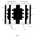
- Figure 5 shows a view of the image as captured by the camera when an integrated circuit, as shown in Figure 4, is used as object 10.
- a first side view 31 is projected by one of the lightings 3 by projecting the contours of one reference edge 12 of the datum 1, of the package body 82 and of the leads 81 of one side of the integrated circuit 10 through the aperture 2 and along the first projection path 91 as well as along the second projection path 92 selected by the optical prism 5.
- the rhomboid prism 8 redirects the two projection paths 91 and 92 in parallel and towards the optical axis of the system.
- a symmetrical arrangement of the optical prism 5, the rhomboid prism 8, a lighting 3 as well as the reference edge 12 of the datum 1 can provide a second side view, as shown in Figure 5, which is projected in the same way as the first side view is projected.
Landscapes
- General Health & Medical Sciences (AREA)
- Physics & Mathematics (AREA)
- Life Sciences & Earth Sciences (AREA)
- Chemical & Material Sciences (AREA)
- Analytical Chemistry (AREA)
- Biochemistry (AREA)
- Health & Medical Sciences (AREA)
- General Physics & Mathematics (AREA)
- Immunology (AREA)
- Pathology (AREA)
- Investigating Materials By The Use Of Optical Means Adapted For Particular Applications (AREA)
- Testing Or Measuring Of Semiconductors Or The Like (AREA)
- Length Measuring Devices By Optical Means (AREA)
- Tests Of Electronic Circuits (AREA)
Applications Claiming Priority (3)
| Application Number | Priority Date | Filing Date | Title |
|---|---|---|---|
| SG200001912 | 2000-03-31 | ||
| SG200001912 | 2000-03-31 | ||
| SG0019125 | 2000-03-31 |
Publications (2)
| Publication Number | Publication Date |
|---|---|
| EP1139090A2 true EP1139090A2 (fr) | 2001-10-04 |
| EP1139090A3 EP1139090A3 (fr) | 2004-04-21 |
Family
ID=29268178
Family Applications (1)
| Application Number | Title | Priority Date | Filing Date |
|---|---|---|---|
| EP01108209A Withdrawn EP1139090A3 (fr) | 2000-03-31 | 2001-03-30 | Appareil d'inspection de circuits integrés avec fils de connexion |
Country Status (2)
| Country | Link |
|---|---|
| EP (1) | EP1139090A3 (fr) |
| JP (1) | JP2001336919A (fr) |
Cited By (3)
| Publication number | Priority date | Publication date | Assignee | Title |
|---|---|---|---|---|
| WO2004079427A1 (fr) * | 2003-03-07 | 2004-09-16 | Ismeca Semiconductor Holding Sa | Dispositif optique et module d'inspection |
| US10871456B2 (en) | 2019-02-07 | 2020-12-22 | Kabushiki Kaisha Toshiba | Semiconductor inspection system and semiconductor inspection apparatus |
| CN112462234A (zh) * | 2020-11-27 | 2021-03-09 | 日月光半导体(昆山)有限公司 | 集成电路测试方法、计算机可读介质以及集成电路测试装置 |
Families Citing this family (1)
| Publication number | Priority date | Publication date | Assignee | Title |
|---|---|---|---|---|
| US7635729B2 (en) | 2005-09-29 | 2009-12-22 | Raymond Lee Nip | Zinc oxide coated particles, compositions containing the same, and methods for making the same |
Citations (5)
| Publication number | Priority date | Publication date | Assignee | Title |
|---|---|---|---|---|
| EP0458473A1 (fr) * | 1990-05-22 | 1991-11-27 | Emhart Inc. | Machine de montage en surface |
| JPH1093846A (ja) * | 1996-09-12 | 1998-04-10 | Copal Co Ltd | 撮像装置 |
| US6088108A (en) * | 1998-08-27 | 2000-07-11 | Hewlett-Packard Company | Leaded components inspection system |
| WO2002017357A2 (fr) * | 2000-08-22 | 2002-02-28 | Agilent Technologies, Inc. | Inspection tridimensionnelle de circuits integres a broches de raccordement |
| WO2002045136A2 (fr) * | 2000-11-28 | 2002-06-06 | Semiconductor Technologies & Instruments, Inc. | Systeme d'inspection tridimensionnelle de broches de raccordement |
-
2001
- 2001-03-27 JP JP2001089223A patent/JP2001336919A/ja active Pending
- 2001-03-30 EP EP01108209A patent/EP1139090A3/fr not_active Withdrawn
Patent Citations (5)
| Publication number | Priority date | Publication date | Assignee | Title |
|---|---|---|---|---|
| EP0458473A1 (fr) * | 1990-05-22 | 1991-11-27 | Emhart Inc. | Machine de montage en surface |
| JPH1093846A (ja) * | 1996-09-12 | 1998-04-10 | Copal Co Ltd | 撮像装置 |
| US6088108A (en) * | 1998-08-27 | 2000-07-11 | Hewlett-Packard Company | Leaded components inspection system |
| WO2002017357A2 (fr) * | 2000-08-22 | 2002-02-28 | Agilent Technologies, Inc. | Inspection tridimensionnelle de circuits integres a broches de raccordement |
| WO2002045136A2 (fr) * | 2000-11-28 | 2002-06-06 | Semiconductor Technologies & Instruments, Inc. | Systeme d'inspection tridimensionnelle de broches de raccordement |
Non-Patent Citations (1)
| Title |
|---|
| PATENT ABSTRACTS OF JAPAN vol. 1998, no. 09, 31 July 1998 (1998-07-31) -& JP 10 093846 A (COPAL CO LTD), 10 April 1998 (1998-04-10) * |
Cited By (4)
| Publication number | Priority date | Publication date | Assignee | Title |
|---|---|---|---|---|
| WO2004079427A1 (fr) * | 2003-03-07 | 2004-09-16 | Ismeca Semiconductor Holding Sa | Dispositif optique et module d'inspection |
| US7283235B2 (en) | 2003-03-07 | 2007-10-16 | Ismeca Semiconductor Holding Sa | Optical device and inspection module |
| US10871456B2 (en) | 2019-02-07 | 2020-12-22 | Kabushiki Kaisha Toshiba | Semiconductor inspection system and semiconductor inspection apparatus |
| CN112462234A (zh) * | 2020-11-27 | 2021-03-09 | 日月光半导体(昆山)有限公司 | 集成电路测试方法、计算机可读介质以及集成电路测试装置 |
Also Published As
| Publication number | Publication date |
|---|---|
| JP2001336919A (ja) | 2001-12-07 |
| EP1139090A3 (fr) | 2004-04-21 |
Similar Documents
| Publication | Publication Date | Title |
|---|---|---|
| US4867570A (en) | Three-dimensional information processing method and apparatus for obtaining three-dimensional information of object by projecting a plurality of pattern beams onto object | |
| US6611344B1 (en) | Apparatus and method to measure three dimensional data | |
| US6879403B2 (en) | Three dimensional scanning camera | |
| KR101150755B1 (ko) | 영상촬영장치 | |
| TWI427265B (zh) | 測量裝置 | |
| WO1998012502A1 (fr) | Dispositif imageur d'objet a controler et dispositif de controle de boitiers de semi-conducteurs | |
| TWI500901B (zh) | 測量裝置 | |
| US20100295938A1 (en) | Apparatus for the Optical Inspection of Wafers | |
| US9594028B2 (en) | Method and apparatus for determining coplanarity in integrated circuit packages | |
| CN102116745A (zh) | 一种ic元件检测系统 | |
| JP5034891B2 (ja) | 透明板状体の形状測定装置及び板ガラスの製造方法 | |
| JPH045508A (ja) | 物体の形状検出方法及びその装置 | |
| WO2002017357A2 (fr) | Inspection tridimensionnelle de circuits integres a broches de raccordement | |
| US5572368A (en) | Light projecting device with cylindrical lens | |
| KR100849653B1 (ko) | 전자 컴포넌트의 콘택트 엘리먼트의 위치를 측정하기 위한방법 및 장치 | |
| EP1139090A2 (fr) | Appareil d'inspection de circuits integrés avec fils de connexion | |
| JP2007170948A (ja) | 幅測定装置、端部位置検出装置、端部厚さ測定装置、及び形状測定装置 | |
| JP2677351B2 (ja) | 立体状被検体外面検査装置 | |
| KR20020093507A (ko) | 부품 검사 장치 | |
| WO2002045136A9 (fr) | Systeme d'inspection tridimensionnelle de broches de raccordement | |
| CN114543706A (zh) | 一种基于非相干光源多角度投射的差分光切线扫轮廓术 | |
| US20140340507A1 (en) | Method of measuring narrow recessed features using machine vision | |
| JP2009174918A (ja) | 欠陥検査装置、欠陥検査方法及び板状体の製造方法 | |
| KR20190003363A (ko) | 라인 폭 측정 시스템 및 장치 | |
| JPS62291512A (ja) | 距離測定装置 |
Legal Events
| Date | Code | Title | Description |
|---|---|---|---|
| PUAI | Public reference made under article 153(3) epc to a published international application that has entered the european phase |
Free format text: ORIGINAL CODE: 0009012 |
|
| AK | Designated contracting states |
Kind code of ref document: A2 Designated state(s): AT BE CH CY DE DK ES FI FR GB GR IE IT LI LU MC NL PT SE TR |
|
| AX | Request for extension of the european patent |
Free format text: AL;LT;LV;MK;RO;SI |
|
| RAP1 | Party data changed (applicant data changed or rights of an application transferred) |
Owner name: AGILENT TECHNOLOGIES, INC. (A DELAWARE CORPORATION |
|
| PUAL | Search report despatched |
Free format text: ORIGINAL CODE: 0009013 |
|
| RIC1 | Information provided on ipc code assigned before grant |
Ipc: 7H 05K 13/04 B Ipc: 7H 05K 13/08 B Ipc: 7G 01B 11/30 B Ipc: 7G 01N 21/956 B Ipc: 7G 01B 11/24 B Ipc: 7G 01N 21/88 A |
|
| AK | Designated contracting states |
Kind code of ref document: A3 Designated state(s): AT BE CH CY DE DK ES FI FR GB GR IE IT LI LU MC NL PT SE TR |
|
| AX | Request for extension of the european patent |
Extension state: AL LT LV MK RO SI |
|
| AKX | Designation fees paid | ||
| REG | Reference to a national code |
Ref country code: DE Ref legal event code: 8566 |
|
| STAA | Information on the status of an ep patent application or granted ep patent |
Free format text: STATUS: THE APPLICATION IS DEEMED TO BE WITHDRAWN |
|
| 18D | Application deemed to be withdrawn |
Effective date: 20041022 |