EP2239552B1 - Image picking-up device for lens - Google Patents
Image picking-up device for lens Download PDFInfo
- Publication number
- EP2239552B1 EP2239552B1 EP08865745.7A EP08865745A EP2239552B1 EP 2239552 B1 EP2239552 B1 EP 2239552B1 EP 08865745 A EP08865745 A EP 08865745A EP 2239552 B1 EP2239552 B1 EP 2239552B1
- Authority
- EP
- European Patent Office
- Prior art keywords
- lens
- light
- mark
- image sensing
- test
- Prior art date
- Legal status (The legal status is an assumption and is not a legal conclusion. Google has not performed a legal analysis and makes no representation as to the accuracy of the status listed.)
- Not-in-force
Links
Images


Classifications
-
- G—PHYSICS
- G01—MEASURING; TESTING
- G01M—TESTING STATIC OR DYNAMIC BALANCE OF MACHINES OR STRUCTURES; TESTING OF STRUCTURES OR APPARATUS, NOT OTHERWISE PROVIDED FOR
- G01M11/00—Testing of optical apparatus; Testing structures by optical methods not otherwise provided for
- G01M11/02—Testing optical properties
- G01M11/0242—Testing optical properties by measuring geometrical properties or aberrations
- G01M11/0257—Testing optical properties by measuring geometrical properties or aberrations by analyzing the image formed by the object to be tested
-
- G—PHYSICS
- G01—MEASURING; TESTING
- G01N—INVESTIGATING OR ANALYSING MATERIALS BY DETERMINING THEIR CHEMICAL OR PHYSICAL PROPERTIES
- G01N21/00—Investigating or analysing materials by the use of optical means, i.e. using sub-millimetre waves, infrared, visible or ultraviolet light
- G01N21/84—Systems specially adapted for particular applications
- G01N21/88—Investigating the presence of flaws or contamination
- G01N21/95—Investigating the presence of flaws or contamination characterised by the material or shape of the object to be examined
- G01N21/958—Inspecting transparent materials or objects, e.g. windscreens
-
- G—PHYSICS
- G01—MEASURING; TESTING
- G01N—INVESTIGATING OR ANALYSING MATERIALS BY DETERMINING THEIR CHEMICAL OR PHYSICAL PROPERTIES
- G01N21/00—Investigating or analysing materials by the use of optical means, i.e. using sub-millimetre waves, infrared, visible or ultraviolet light
- G01N21/84—Systems specially adapted for particular applications
- G01N21/88—Investigating the presence of flaws or contamination
- G01N21/95—Investigating the presence of flaws or contamination characterised by the material or shape of the object to be examined
- G01N2021/9511—Optical elements other than lenses, e.g. mirrors
Definitions
- the present invention relates to a lens image sensing apparatus used to detect, e.g., a hidden mark on a spectacle lens, a scratch on the lens surface, a foreign substance adhering on the lens, chipping or cracking of the lens, internal defects (striae, resin flow hysteresis, and weld lines) of the lens, and the optical characteristics of the lens.
- a lens image sensing apparatus used to detect, e.g., a hidden mark on a spectacle lens, a scratch on the lens surface, a foreign substance adhering on the lens, chipping or cracking of the lens, internal defects (striae, resin flow hysteresis, and weld lines) of the lens, and the optical characteristics of the lens.
- a spectacle lens such as a progressive multifocal lens includes a plurality of convex (or concave) marks which are inscribed on it at reference positions spaced apart from the geometric center by predetermined distances and are called hidden marks (to be simply referred to as marks hereinafter).
- the spectacle lens is designed such that its geometric center, distance and near optical centers, and eyepoint position, for example, are calculated from the positions of these marks. For this reason, in edging the lens, an eyepoint position is detected from the positions of these marks, and a lens holder is mounted at the eyepoint position.
- a spectacle lens image sensing apparatus disclosed in Japanese Patent Laid-Open No. 2002-022599 is known to be used to detect the marks inscribed on the spectacle lens.
- the spectacle lens image sensing apparatus includes a light source, half mirror, and image sensing device placed on the side of the convex surface of a test lens, and a condenser lens, imaging lens, and reflective screen placed on the side of the concave surface of the test lens.
- the convex surface of the test lens is irradiated with light from the light source to project images of the marks formed on the convex surface onto the reflective screen.
- the images reflected by the reflective screen are returned to the side of the convex surface of the test lens, formed again on the light-receiving surface of the image sensing device via the half mirror, and processed by an image processing device, thereby calculating, e.g., the geometric center and eyepoint position of the test lens.
- the reflective screen is formed by attaching a reflecting sheet coated with a fine powder of, e.g., glass or aluminum to a rotary plate in order to reflect light.
- the document EP 1 739 472 A1 relates to a jig mounting apparatus which has a detection optical system that detects reference marker of an eyeglass lens and which is configured so as to determine an mounting point based on the reference marker detected by the detection optical system and position the mounting center of jig, which is used in processing the eyeglass lens, on the mounting point to mount the jig on the surface of the eyeglass lens,
- the detection optical system includes: a focusing optical system that focuses a light-emitting optical flux from a light source on the surface of the eyeglass lens, where hidden marks are formed, via an aperture stop; a reflection plate that reflects an optical flux focused by the focusing optical system and passed through the eyeglass lens;; and an imaging device that is provided on a position optically approximately conjugate with the aperture stop and configured to focus on a space portion along an optical axis direction from the surface of the eyeglass lens.
- the document CA 2 413 343 A1 refers to optical inspection and, particularly, to a method and apparatus for the automatic optical inspection of optical objects for cosmetic defects consisting of surface flaws and occlusions, which cause variations of their local optical properties.
- the document JP 2002 162655 describes a laser beam emitted from a UV solid-state laser which is made incident on a biaxial double refracting crystal.
- the laser beam is formed to the beam shape of the ring band form by this biaxial double refracting crystal and is condensed to a semiconductor wafer by an objective lens.
- the document JP 2001 524663 A describes a razing incidence interferometer which includes an extended light source for limiting spatial coherence of reference and test beams.
- a test plate is oriented at a grazing incidence to the test beam so that a first portion of the test beam is reflected from the front surface of the test plate, a second portion of the test beam is reflected from the back surface of the test plate, and the two test beam portions are sheared with respect to each other.
- the spatial coherence of the test beam is related to the lateral shear between the first and second test beam portions to significantly reduce contrast of an interference fringe pattern between the front and back surfaces of the test plate.
- the reference beam is realigned with just one of the two test beam portions to favor the formation of an interference pattern between the reference surface and one of the front and back surfaces of the test plate over the formation of an interference pattern between the reference surface and the other of the front and back surfaces of the test plate.
- the document JP 2007 526996 relates to a spectacle lens brand name marking test procedure uses a measurement light beam and illumination light beam from separate sources with a periodic, tilting, rotating or linearly moving reflector returning the beam to a camera synchronised to the reflector with contrast increase by image convolution.
- test lens is made of, for example, a thick bulk material (e.g., a strong-minus-power spectacle lens).
- a thick bulk material e.g., a strong-minus-power spectacle lens.
- the present invention has been made to solve the above-described conventional problems and meet the above-described demands, and has as its object to provide a high-reliability lens image sensing apparatus which can obtain a sharp image with large differences in luminance between light beams transmitted through marks on a lens and those transmitted through non-mark portions on the lens.
- a lens image sensing apparatus comprises a light source, an optical device including a collimator lens which converts light emitted by the light source into collimated light, and guides the collimated light to a convex surface of a test lens, a rotary reflector which reflects the light transmitted through the test lens back to the test lens, an image sensing device which receives the light that is reflected by the rotary reflector and transmitted through the test lens and the collimator lens again, an aperture stop arranged in an optical path between the collimator lens and the image sensing device, and a re-imaging lens provided between the aperture stop and the image sensing device, the rotary reflector including a sheet formed from a plurality of corner cube prisms, wherein the sheet is concavely curved when viewed from a side of said light source.
- the corner cube prisms have three orthogonal total reflecting surfaces to have a retroreflection function and they reflect light emitted by the light source in the same direction as its incident direction.
- a concave or convex mark is inscribed on the convex surface of the test lens, especially the periphery of this mark has a surface curvature different from that of the lens surface, so a light beam which enters this periphery diverges.
- a light beam which enters the lens from a lens surface portion (non-mark portion) other than that where the mark is inscribed is reflected by the corner cube prisms, and is transmitted through the periphery of the mark diverges on this periphery as well.
- light which is transmitted through the periphery of the mark diverges, and returns in the same direction as its incident direction (such light will be referred to as diverging retroreflected light hereinafter) has a luminance lower than that of light which is transmitted through only the non-mark portion and retroreflected by the prisms (such light will be referred to as retroreflected light hereinafter).
- a light beam converted into a collimated light beam by the collimator lens has a diameter significantly larger than that of a light beam converted into a collimated light beam by the collimator lens upon passing through only the non-mark portion.
- the illuminance on the light-receiving surface of the image sensing device becomes significantly lower in the mark portion than in the non-mark portion by setting the entrance pupil diameter of the re-imaging lens for forming an image of the test lens surface on the light-receiving surface of the image sensing device to be smaller than the diameter of a collimated light beam generated by the diverging retroreflected light and to be larger than the diameter of a collimated light beam generated by the retroreflected light. This makes it possible to sense a sharp image of the mark.
- test lens is a diverging progressive multifocal lens, and hidden marks (to be simply referred to as marks hereinafter) are formed on the convex surface of the lens will be given.
- reference numeral 1 denotes a test lens serving as a plastic progressive multifocal lens with a circular shape (e.g., with a diameter of 80 mm), which has a polished, convex surface 1a.
- Reference numeral 2 denotes a horizontal reference line which passes through a geometric center O of the test lens 1; and 3A, 3B, and 3C, marks respectively formed on the convex surface 1a.
- the marks 3A, 3B, and 3C are formed of minute projections (e.g., with a height of about 2 to 4 ⁇ m).
- the two marks 3A and 3B are formed at two points spaced apart from the geometric center O to the left and right sides by an equal distance (e.g., 17 mm) on the horizontal reference line 2.
- the marks 3A and 3B are inscribed as identical small circles, or a small circle and a character.
- a number 4 indicating the addition power (the difference in front-side vertex power between a distance portion and a near portion) of the test lens 1, and an identification mark 5 indicating the type of lens are inscribed in the form of minute projections as well at positions below the marks 3A and 3B, respectively.
- the number 4 indicating the addition power is inscribed as a three-digit number (e.g., 300) at a position below the mark 3A positioned on the ear side when one wears the spectacle lens.
- test lens 1 is a left-eye lens or a right-eye lens
- Fig. 4 shows a right-eye lens having the left mark 3A inscribed as a small circle "o", and the mark 3B inscribed as an alphabet "H”.
- the mark 3C is a spectacle shop identification mark, is formed in, for example, a round convex shape, and is inscribed on the convex surface 1a at a position near its outer periphery.
- the test lens 1 serving as a progressive multifocal lens includes a distance power measuring portion 6, a near power measuring portion 7, a portion for distance vision (distance portion) 8, a portion for near vision (near portion) 9, and a portion whose dioptric power continuously changes (progressive portion) 10.
- the positions of the distance power measuring portion 6, the near power measuring portion 7, and an eyepoint 11 of the test lens 1 change depending on the lens design, and are determined at predetermined reference positions spaced apart from the geometric center O.
- the eyepoint 11 is at a position spaced apart from the geometric center O to the upper side by a predetermined distance d 1 (e.g., 2 mm)
- a distance center 12 is at a position spaced apart from the position of the eyepoint 11 to the upper side by a predetermined distance d 2 (e.g., 4 mm).
- d 1 e.g., 2 mm
- a distance center 12 is at a position spaced apart from the position of the eyepoint 11 to the upper side by a predetermined distance d 2 (e.g., 4 mm).
- a lens image sensing apparatus 30 includes a light source 31 placed on the side of the convex surface 1a of the test lens 1, and an optical device 32 which guides light beams L emitted by the light source 31 to the test lens 1.
- the light source 31 is used to irradiate the test lens 1 to obtain sharp images of the marks 3A, 3B, and 3C, the number 4 indicating the addition power, and the identification mark 5, and is a monochromatic point source.
- the monochromatic point source is a general term including a laser light source that is a point source, and a light source, such as an LED, that can be substantially regarded to be a point source. Note that this exemplifies a red semiconductor laser as the point source.
- the optical device 32 includes a condenser lens 33, transmission rotary scattering plate 34, half mirror 35, and collimator lens 36.
- the condenser lens 33 focuses the light beams L emitted by the light source 31.
- the transmission rotary scattering plate 34 is placed in front of the condenser lens 33.
- the half mirror 35 guides the light beams L transmitted through the transmission rotary scattering plate 34 toward the test lens 1.
- the collimator lens 36 is provided between the half mirror 35 and the test lens 1, and converts the light beams L from the light source 31 into collimated light beams L 1 .
- the transmission rotary scattering plate 34 is used to eliminate any speckles and fringes, and serves as a transparent scatterer made of, e.g., glass.
- the transmission rotary scattering plate 34 is configured to be rotated by a driving motor (not shown) at the time of measuring the marks on the test lens 1 so as to scatter the light beams L from the light source 31. For this reason, the transmission rotary scattering plate 34 has a coarse surface 34a facing the half mirror 35, and is placed at a focal position P 1 of the condenser lens 33.
- the half mirror 35 has an appropriate transmittance and reflectance: it reflects the light beams L, which are emitted by the light source 31 and transmitted through the condenser lens 33 and transmission rotary scattering plate 34, toward the test lens 1, and transmits light beams L 2 and L 3 which return from the side of the test lens 1.
- the collimator lens 36 is arranged in the optical path between the test lens 1 and the half mirror 35.
- the collimator lens 36 converts the light beams L, which are emitted by the light source 31, transmitted through the condenser lens 33 and transmission rotary scattering plate 34, and reflected by the half mirror 35, into the collimated light beams L 1 .
- test lens 1 is placed at a focal position P 2 of the collimator lens 36 on its lower side.
- An aperture stop 37, bandpass filter 38, re-imaging lens 39, image sensing device 40, and image processing device 41 are placed on the side of the half mirror 35 opposite to that of the test lens 1.
- the aperture stop 37 is placed at a focal position P 3 of the collimator lens 36 on its upper side, and limits the diameter of the light beam coming from the collimator lens 36. More specifically, the aperture stop 37 has a diameter which is smaller than that of a light beam from the mark 3C on the convex surface 1a of the test lens 1, and is larger than that of a light beam from a non-mark portion.
- the position of the aperture stop 37 is not limited to the focal position P 3 of the collimator lens 36. The same function can also be realized by placing the aperture stop 37 at the position of the exit pupil of the collimator lens 36.
- the bandpass filter 38 serves to transmit only light in the wavelength range of the light source 31 and cut off ambient light, and is provided between the aperture stop 37 and the re-imaging lens 39.
- the re-imaging lens 39 focuses the light beams L 2 and L 3 having passed through the bandpass filter 38 on the image sensing device 40.
- the image sensing device 40 includes a plurality of CCDs 40A which form a light-receiving surface, and is electrically connected to the image processing device 41.
- the CCDs 40A are placed at a focal position P 4 of the re-imaging lens 39.
- the focal position P 4 of the re-imaging lens 39 is conjugate to the position of the convex surface 1a of the test lens 1 on the side of the collimator lens 36.
- the lens image sensing apparatus 30 also includes a lens holding device 42 and rotary reflector 43 placed on the side of a concave surface 1b of the test lens 1.
- the lens holding device 42 serves to chuck and fix the center of the concave surface 1b of the test lens 1, and includes a transparent plate 45 and a lens chucking cylinder 46 standing upright at the center of the upper surface of the transparent plate 45.
- the lens holding device 42 is configured to chuck and fix the center of the concave surface 1b of the test lens 1 on the upper surface of the lens chucking cylinder 46 by evacuating the lens chucking cylinder 46 using a vacuum pump.
- the lens chucking cylinder 46 has an outer diameter (e.g., 8 mm) small enough not to hamper projection of the marks 3A, 3B, and 3C, the number 4 indicating the addition power, and the identification mark 5 on the test lens 1.
- the rotary reflector 43 serves to retroreflect the light beams L 1 . transmitted through the test lens 1 in the same directions as their incident directions, and includes a rotary plate 47 and a corner cube prism sheet 48 attached to the surface of the rotary plate 47.
- the corner cube prism sheet 48 is made of plastic with a thickness of about 0.3 mm to 0.5 mm, includes a plurality of corner cube prisms (to be also simply referred to as prisms hereinafter) 49 formed on its surface, and is protected by a transparent protective film over the entire surface.
- the prisms 49 themselves are conventionally known prisms, which have three orthogonal total reflecting surfaces to have a function of reflecting the collimated light beams L 1 transmitted through the test lens 1 in the same directions as their incident directions, i.e., a retroreflection function.
- the rotary reflector 43 is configured to be rotated at high speed (e.g., at 3,400 rpm) by a driving motor (not shown) in order to uniform its surface brightness and background, like the transmission rotary scattering plate 34.
- Fig. 1 shows only three light beams L scattered by the transmission rotary scattering plate 34. These scattered light beams L are reflected by the half mirror 35, are converted into two collimated light beams L 1 and one collimated light beam L 2 , irradiate the mark 3C and two non-mark portions on the test lens 1, are retroreflected by the prisms 49, and focus on the CCDs 40A of the image sensing device 40 as four light beams L 2 and L 3 .
- light beams which irradiate other different portions on the test lens 1 and are transmitted through them similarly focus on the CCDs 40A and form images on them, as a matter of course.
- test lens 1 is provided into the opening in the upper surface of the lens chucking cylinder 46 with the convex surface 1a facing up.
- a vacuum exhaust device evacuates the lens chucking cylinder 46 to chuck and fix the test lens 1 in the opening in the upper surface of the lens chucking cylinder 46.
- the light source 31 is turned on to emit light beams (red laser beams) L.
- the light beams L emitted by the light source 31 are focused by the condenser lens 33.
- the light beams L are converted into scattered light beams upon being transmitted through the transmission rotary scattering plate 34.
- the light beams L strike the half mirror 35, are reflected toward the test lens 1, and are further converted into collimated light beams L 1 upon being transmitted through the collimator lens 36.
- the collimated light beams L 1 become diverging light beams upon being transmitted through the test lens 1 from the convex surface 1a to the concave surface 1b (the collimated light beams L 1 become converging light beams when the test lens 1 is a convex converging dioptric lens).
- the collimated light beam L 1 which enters the test lens 1 from a lens surface portion (non-mark portion) other than that where the mark is inscribed strikes the prisms 49, is reflected by the prisms 49 in the same direction as its incident direction to the prisms 49.
- the light beam L 2 is transmitted through the test lens 1 from the concave surface 1b, and returns to the convex surface 1a, as shown in Fig. 2 .
- a reflected light beam L 2 diffuses upon being transmitted through the test lens 1. Nevertheless, because the degree of diffusion of the light beam transmitted through the non-mark portion on the convex surface 1a is small enough to be ignored, the light beam L 2 becomes a retroreflected light beam with a sufficiently small diameter.
- the retroreflected light beam L 2 passes through the aperture stop 37 with little loss after being transmitted through the collimator lens 36 again.
- the retroreflected light beam L 2 having passed through the aperture stop 37 is transmitted through the bandpass filter 38 and re-imaging lens 39, and focused on the CCDs 40A of the image sensing device 40, thereby forming a bright image.
- the collimated light beam L 1 transmitted through the collimator lens 36 strikes and is retroreflected by the prisms 49 upon being transmitted through the test lens 1, and is transmitted through the test lens 1 again.
- the reflected light beam L 3 diffuses upon being transmitted through the mark 3C.
- the degree of diffusion of the reflected light beam L 3 is larger than the retroreflected light beam L 2 transmitted through the non-mark portion mentioned above.
- the light beam L 3 transmitted through the mark 3C becomes a diverging retroreflected light beam, returns in the same direction as its incident direction, is transmitted through the collimator lens 36, and passes through the aperture stop 37 with a considerable loss because its diameter is larger than that of the aperture stop 37.
- the diverging retroreflected light beam L 3 is focused on the CCDs 40A of the image sensing device 40 after being transmitted through the bandpass filter 38 and re-imaging lens 39. This makes it possible to sense a sharp image of the mark 3C because the illuminance of the mark 3C on the CCDs 40A is lower than the non-mark portion.
- the image sensing device 40 converts the light received by the CCDs 40A into an electrical signal, and sends it to the image processing device 41.
- the image processing device 41 processes the image information from the image sensing device 40 to identify a spectacle shop as the delivery destination using the mark 3C. Also, the image sensing device 40 receives the pieces of image information of, e.g., the marks 3A and 3B to calculate the positions of, e.g., the geometric center O and eyepoint 11 based on the pieces of position information of these marks 3A and 3B.
- Fig. 5 is a view showing the route of a light beam which is transmitted through only the non-mark portion and is not transmitted through the mark 3C.
- the test lens 1 is a minus-power lens and the prisms 49 have an appropriate size.
- the collimated light beam L 1 which enters the non-mark portion on the convex surface 1a of the test lens 1 on its periphery is transmitted through the test lens 1, becomes a diffused light beam, enters the corner cube prisms 49, and is totally reflected in the same direction as its incident direction by the prisms 49.
- the reflected light beam L 1 enters the concave surface 1b of the test lens 1, is transmitted through the test lens 1 again, and exits the non-mark portion on the convex surface 1a.
- An entrance point X 1 of the collimated light beam L 1 and an exit point X 2 of the light beam (retroreflected light beam) L 2 which is reflected by the prisms 49 and exits the convex surface 1a slightly shift from each other in the optical axis direction of the test lens 1.
- the light beam L 2 which enters and is reflected by the prisms 49 becomes a retroreflected light beam parallel to the collimated light beam L 1 , and travels back the way it came.
- the retroreflected light beam L 2 is transmitted through the collimator lens 36, half mirror 35, aperture stop 37, bandpass filter 38, and re-imaging lens 39 shown in Figs. 1 to 3 , and is focused on the CCDs 40A of the image sensing device 40, thereby forming a bright image.
- Fig. 6 is a view showing the route of a light beam transmitted through the mark 3C and the non-mark portion in this order. Because a periphery C of the mark 3C has a surface curvature quite different from that of the non-mark portion, the collimated light beam L 1 which enters and is transmitted through the periphery C becomes the light beam L 3 , enters the prisms 49, and is totally reflected in the same direction as its incident direction by the prisms 49. The light beam L 3 is transmitted through the non-mark portion on the test lens 1, exits the non-mark portion from an exit point X 3 , becomes a light beam parallel to the collimated light beam L 1 , and travels back the way it came.
- the light beam L 3 is diffused by the periphery C of the mark 3C and therefore becomes a diverging retroreflected light beam with a diameter larger than the retroreflected light beam L 2 which enters the non-mark portion and exits the non-mark portion, mentioned above.
- the diverging retroreflected light beam L 3 passes through the aperture stop 37 with a considerable loss, and has an illuminance on the CCDs 40A, that is lower than the non-mark portion, as described above.
- Fig. 7 is a view for explaining the route of a light beam transmitted through the non-mark portion and the periphery of the mark 3C in this order.
- the collimated light beam L 1 which enters the non-mark portion on the convex surface 1a from a point X 4 near the mark 3C, and is transmitted through the non-mark portion enters the prisms 49, is totally reflected in the same direction as its incident direction by the prisms 49, and exits the periphery C of the mark 3C.
- the collimated light beam L 1 diffuses into a diverging retroreflected reflected light beam L 4 with a large diameter, and exits the convex surface 1a of the test lens 1.
- the diverging retroreflected reflected light beam L 4 passes through the aperture stop 37 with a considerable loss, and has an illuminance on the CCDs 40A, that is lower than the non-mark portion, as described above.
- Fig. 8 is a view showing the route of a light beam which enters the central portion of the mark 3C, and exits the non-mark portion from a point near the mark 3C.
- the collimated light beam L 1 which enters a central portion X 5 of the mark 3C, and is transmitted through the test lens 1 enters the prisms 49, is totally reflected in the same direction as its incident direction by the prisms 49, is transmitted through the non-mark portion on the test lens 1, and exits the non-mark portion from an exit point X 6 . Because the central portion of the periphery C has a surface curvature close to that of the non-mark portion, the degree of diffusion of the collimated light beam L 1 by the mark 3C is very small.
- the collimated light beam L 1 exits the convex surface 1a of the test lens 1 from the exit point X 6 as a retroreflected light beam L 5 with a small diameter.
- the retroreflected light beam L 5 is transmitted through the bandpass filter 38 and re-imaging lens 39, and focused on the CCDs 40A of the image sensing device 40 without any loss due to factors associated with the aperture stop 37, thereby forming a bright image, like the light beam L 2 shown in Figs. 2 and 5 .
- Fig. 9 is a view showing the route of a light beam which enters the non-mark portion from a point near the mark 3C, is transmitted through the non-mark portion, and exits the central portion of the mark 3C upon re-transmission.
- the collimated light beam L 1 which enters the non-mark portion on the test lens 1 from a point X 7 near the mark 3C, and is transmitted through the test lens 1 enters the prisms 49, and is totally reflected in the same direction as its incident direction by the prisms 49.
- a reflected light beam L 6 exits the central portion X 5 of the mark 3C.
- the reflected light beam L 6 is transmitted through the central portion X 5 of the mark 3C with little diffusion, and exits the convex surface 1a of the test lens 1 from the central portion X 5 as a retroreflected light beam with a small diameter.
- the reflected light beam L 6 is transmitted through the bandpass filter 38 and re-imaging lens 39, and focused on the CCDs 40A without any loss due to factors associated with the aperture stop 37, thereby forming a bright image, like the retroreflected light beams L 2 and L 5 .
- the light beams L 2 , L 5 , and L 6 transmitted through only the non-mark portion on the convex surface 1a in both the forward and backward paths are returned as retroreflected light beams with small degrees of diffusion, and focused on the light-receiving surface of the CCDs 40A.
- the light beams L 3 and L 4 transmitted through the periphery C of the mark 3C in at least one of the forward and backward paths are returned as diverging retroreflected light beams with large degrees of diffusion, and focused on the light-receiving surface of the CCDs 40A.
- the retroreflected light beams L 2 , L 5 , and L 6 and the diverging retroreflected light beams L 3 and L 4 are guided to the aperture stop 37, the retroreflected light beams L 2 , L 5 , and L 6 pass through the aperture stop 37 without any losses because they have sufficiently small diameters.
- the retroreflected light beams L 2 , L 5 , and L 6 can generate high illuminances of the mark on the light-receiving surface of the CCDs 40A.
- the diverging retroreflected light beams L 3 and L 4 have diameters larger than that of the aperture stop 37, so they generate low illuminances of the mark on the light-receiving surface of the CCDs 40A because their losses due to factors associated with the aperture stop 37 are large.
- the lens image sensing apparatus 30 can obtain a mark image which is sharper and has a higher contrast than that obtained using the above-mentioned conventional reflective screen. This makes it possible to facilitate image processing, and, in turn, facilitate design of an image processing circuit.
- Fig. 10 is a view showing an image of the mark 3C obtained by the apparatus.
- an image of the mark 3C formed on the CCDs 40A of the image sensing device 40 has a dark periphery, a bright central portion, and a clear contour shape, and these features facilitate image processing by the image processing device 41.
- the transmission rotary scattering plate 34 Since the transmission rotary scattering plate 34 is used, generation of any speckles due to factors associated with the laser light source can be suppressed and prevented. Also, since the brightness of the surface of the corner cube prism sheet 48 in the image background is equalized by the rotary reflector 43, image processing can further be facilitated.
- test lens 1 is a colored lens, it is possible to obtain a sharp image with high contrast as long as the mark has a shape which can obtain retroreflected light and diverging retroreflected light.
- the ratio between the focal length (f 1 ) of the collimator lens 36 and the focal length (f 2 ) of the re-imaging lens 39 becomes sufficiently high. This makes it possible to set the longitudinal magnification sufficiently high as well, thus increasing the depth of focus. This has the advantage of minimizing defocusing at the time of observing a thick lens, thus reducing the shadows of the end face of a minus-power lens.
- the light beams L emitted by the light source 31 are converted into the collimated light beams L 1 by the collimator lens 36.
- the exit light from the collimator lens 36 obliquely enters the end face of the test lens 1. Therefore, this incident light strikes and is reflected by the edge surface, does not become effective retroreflected light even when it is reflected by the prisms 49, and is not focused on the CCDs 40A of the image sensing device 40. This makes it impossible to obtain a sharp image.
- the exit light from the collimator lens 36 enters the end face of a minus-power lens at a large incident angle. Therefore, this incident light is refracted toward the lens center without striking the edge surface, becomes retroreflected light upon being reflected by the prisms 49 after its transmission through the lens, travels back the way it came, and is focused on the CCDs 40A. This makes it possible to obtain a sharp image.
- a conjugate optical system including the collimator lens 36 and re-imaging lens 39 is designed as a bilateral telecentric optical system, this is preferable because an image with the same barycentric position as an image free from defocusing can be obtained even if defocusing occurs upon fluctuation in thickness of the test lens 1.
- a concave mark is symmetrical to a convex mark and has, on the periphery of its concave portion, a surface curvature quite different from that of the convex surface 1a of the test lens 1, light transmitted through the periphery has a large degree of diffusion and therefore becomes diverging retroreflected light, whereas light transmitted through the central portion of the concave portion has a small degree of diffusion and therefore becomes retroreflected light. This makes it possible to obtain a mark image with a clear contour shape and high contrast between the retroreflected light and the diverging retroreflected light.
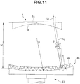
- Fig. 11 is a sectional view showing a corner cube prism sheet according to the embodiment of the present invention.
- a corner cube prism sheet 48 is concavely curved on the light source side instead of being formed in a flat shape.
- Other constituent components in this embodiment are quite the same as the ones shown in Fig. 1 .
- corner cube prism sheet 48 is formed in a flat shape, as indicated by an alternate long and two short dashed line.
- a light beam L 1 farther away from the center of a test lens 1 has a larger incident angle ⁇ on the surface of corner cube prisms 49.
- the corner cube prisms 49 exhibit low reflection efficiency. That is, a large light loss is generated, and this darkens the entire image. This means that a sharp image is hard to obtain when a mark is inscribed on the test lens 1 near its outer periphery.
- the corner cube prism sheet 48 is concavely curved when viewed from the light source side. Then, the light beam L 1 farther away from the center of the test lens 1 can have an incident angle ⁇ on the surface of the corner cube prisms 49, that is smaller than when the corner cube prism sheet 48 is flat. Thus, the corner cube prisms 49 exhibit high reflection efficiency, and this makes it possible to reduce a light loss. In this way, a sharp image can be obtained even when a mark inscribed on the test lens 1 near its outer periphery is used.
- the corner cube prism sheet 48 has too large a radius of curvature R, it has a shape close to that of a flat plate, and this lessens the effect produced by the corner cube prism sheet 48. If the corner cube prism sheet 48 has too small a radius of curvature R, a light beam which passes through the test lens 1 near its periphery enters the corner cube prism sheet 48 at a relatively large incident angle, and this generates a light loss.
- the corner cube prism sheet 48 is desirably designed to have a preferable value of the radius of curvature R in accordance with the lens dioptric power.
- the radius of curvature R can be set to a value obtained by adding a correction value that depends on the angle of divergence of the incident light beam to the radius of curvature R.
- the light source used is a monochromatic point source.
- the corner cube prism sheet is concavely curved when viewed from the light source side to reduce a light loss. That is, when the corner cube prism sheet is flat, light transmitted through the test lens at a position farther away from the center of the test lens more obliquely enters the corner cube prism. This generates a light loss due to factors associated with the prism geometrical structure, and lowers reflection efficiency (the intensity ratio between the incident beam and the outgoing beam). This phenomenon is undesirable because it generates a decrease in image luminance on the outer periphery of the test lens, which exhibits especially high divergence, and deteriorates the detection sensitivity of a mark located near the outer periphery.
- the corner cube prism sheet is concavely curved when viewed from the light source side.
- a light beam which passes through a diverging test lens at a position farther away from its center can have an incident angle on the corner cube prisms, that is smaller than when a flat sheet is used. This makes it possible to keep a light loss small enough to be ignored, and, in turn, makes it possible to sense a sharp image of even a mark inscribed on the test lens near its outer periphery.
- a converging test lens shows a decrease in luminance on its outer periphery less conspicuous than a diverging test lens.
- the former lens has a converging optical path from the test lens to the corner cube prism sheet.
- corner cube prism sheet is undesirably convexly curved when viewed from the light source side, a light beam transmitted through the outer periphery of a diverging test lens enters the corner cube prisms at a large incident angle, and this generates a large light loss and lowers reflection efficiency. This makes it impossible to sense a sharp image of the mark.
- the optical device includes a condenser lens, transmission rotary scattering plate, and half mirror.
- the condenser lens focuses light emitted by the light source.
- the transmission rotary scattering plate scatters the light transmitted through the condenser lens.
- the half mirror guides the light transmitted through the transmission rotary scattering plate to the collimator lens, and further guides, to the aperture stop, the light which is transmitted through the test lens, strikes and is reflected by the rotary reflector, is transmitted through the test lens and collimator lens again, and returns.
- the image sensing device includes a bandpass filter which transmits only light in the wavelength range of the light from the light source.
- the bandpass filter transmits only light in the wavelength range of the light from the light source, it is possible to sense an image with high contrast with little influence of ambient light.
- the image sensing device includes an image processing device which processes the image sensed by the image sensing device.
Landscapes
- Physics & Mathematics (AREA)
- General Physics & Mathematics (AREA)
- Chemical & Material Sciences (AREA)
- Analytical Chemistry (AREA)
- Life Sciences & Earth Sciences (AREA)
- Health & Medical Sciences (AREA)
- Geometry (AREA)
- Biochemistry (AREA)
- General Health & Medical Sciences (AREA)
- Immunology (AREA)
- Pathology (AREA)
- Testing Of Optical Devices Or Fibers (AREA)
- Investigating Materials By The Use Of Optical Means Adapted For Particular Applications (AREA)
Description
- The present invention relates to a lens image sensing apparatus used to detect, e.g., a hidden mark on a spectacle lens, a scratch on the lens surface, a foreign substance adhering on the lens, chipping or cracking of the lens, internal defects (striae, resin flow hysteresis, and weld lines) of the lens, and the optical characteristics of the lens.
- A spectacle lens such as a progressive multifocal lens includes a plurality of convex (or concave) marks which are inscribed on it at reference positions spaced apart from the geometric center by predetermined distances and are called hidden marks (to be simply referred to as marks hereinafter). The spectacle lens is designed such that its geometric center, distance and near optical centers, and eyepoint position, for example, are calculated from the positions of these marks. For this reason, in edging the lens, an eyepoint position is detected from the positions of these marks, and a lens holder is mounted at the eyepoint position.
- A spectacle lens image sensing apparatus disclosed in Japanese Patent Laid-Open No.
2002-022599 - The spectacle lens image sensing apparatus includes a light source, half mirror, and image sensing device placed on the side of the convex surface of a test lens, and a condenser lens, imaging lens, and reflective screen placed on the side of the concave surface of the test lens. The convex surface of the test lens is irradiated with light from the light source to project images of the marks formed on the convex surface onto the reflective screen. The images reflected by the reflective screen are returned to the side of the convex surface of the test lens, formed again on the light-receiving surface of the image sensing device via the half mirror, and processed by an image processing device, thereby calculating, e.g., the geometric center and eyepoint position of the test lens. The reflective screen is formed by attaching a reflecting sheet coated with a fine powder of, e.g., glass or aluminum to a rotary plate in order to reflect light.
- The
document EP 1 739 472 A1 relates to a jig mounting apparatus which has a detection optical system that detects reference marker of an eyeglass lens and which is configured so as to determine an mounting point based on the reference marker detected by the detection optical system and position the mounting center of jig, which is used in processing the eyeglass lens, on the mounting point to mount the jig on the surface of the eyeglass lens, in which the detection optical system includes: a focusing optical system that focuses a light-emitting optical flux from a light source on the surface of the eyeglass lens, where hidden marks are formed, via an aperture stop; a reflection plate that reflects an optical flux focused by the focusing optical system and passed through the eyeglass lens;; and an imaging device that is provided on a position optically approximately conjugate with the aperture stop and configured to focus on a space portion along an optical axis direction from the surface of the eyeglass lens. - The
document CA 2 413 343 A1 refers to optical inspection and, particularly, to a method and apparatus for the automatic optical inspection of optical objects for cosmetic defects consisting of surface flaws and occlusions, which cause variations of their local optical properties. - The document
JP 2002 162655 - The document
JP 2001 524663 A - Finally, the document
JP 2007 526996 - Unfortunately, it is often the case that marks are formed on the spectacle lens using different types of marking techniques such as printing, so they are hard to distinguish from the remaining portions due to their variation in sharpness. In addition, in recent years, as marks are inscribed in lighter colors, and high index lenses and colored lenses prevail, the differences in luminance between light beams having passed through the marks and those having passed through portions where no marks are inscribed (to be also referred to as non-mark portions hereinafter) have remarkably reduced. For this reason, it is demanded to develop a high-reliability apparatus which can obtain a sharp image by attaining a contrast higher than that attained by the conventional apparatus.
- Furthermore, assume that the test lens is made of, for example, a thick bulk material (e.g., a strong-minus-power spectacle lens). In this case, if marks are formed on the periphery of the lens, this generates shadows of the marks and therefore makes it difficult to detect them. For this reason, it is also demanded to develop an apparatus which can easily detect marks formed on such a bulk material as well.
- The present invention has been made to solve the above-described conventional problems and meet the above-described demands, and has as its object to provide a high-reliability lens image sensing apparatus which can obtain a sharp image with large differences in luminance between light beams transmitted through marks on a lens and those transmitted through non-mark portions on the lens.
- The invention is defined in
independent claim 1. In order to achieve the above-described object, a lens image sensing apparatus comprises a light source, an optical device including a collimator lens which converts light emitted by the light source into collimated light, and guides the collimated light to a convex surface of a test lens, a rotary reflector which reflects the light transmitted through the test lens back to the test lens, an image sensing device which receives the light that is reflected by the rotary reflector and transmitted through the test lens and the collimator lens again, an aperture stop arranged in an optical path between the collimator lens and the image sensing device, and a re-imaging lens provided between the aperture stop and the image sensing device, the rotary reflector including a sheet formed from a plurality of corner cube prisms, wherein the sheet is concavely curved when viewed from a side of said light source. - The corner cube prisms have three orthogonal total reflecting surfaces to have a retroreflection function and they reflect light emitted by the light source in the same direction as its incident direction. When a concave or convex mark is inscribed on the convex surface of the test lens, especially the periphery of this mark has a surface curvature different from that of the lens surface, so a light beam which enters this periphery diverges. Also, a light beam which enters the lens from a lens surface portion (non-mark portion) other than that where the mark is inscribed, is reflected by the corner cube prisms, and is transmitted through the periphery of the mark diverges on this periphery as well. Accordingly, light which is transmitted through the periphery of the mark, diverges, and returns in the same direction as its incident direction (such light will be referred to as diverging retroreflected light hereinafter) has a luminance lower than that of light which is transmitted through only the non-mark portion and retroreflected by the prisms (such light will be referred to as retroreflected light hereinafter). This means that a light beam converted into a collimated light beam by the collimator lens has a diameter significantly larger than that of a light beam converted into a collimated light beam by the collimator lens upon passing through only the non-mark portion. Hence, the illuminance on the light-receiving surface of the image sensing device becomes significantly lower in the mark portion than in the non-mark portion by setting the entrance pupil diameter of the re-imaging lens for forming an image of the test lens surface on the light-receiving surface of the image sensing device to be smaller than the diameter of a collimated light beam generated by the diverging retroreflected light and to be larger than the diameter of a collimated light beam generated by the retroreflected light. This makes it possible to sense a sharp image of the mark.
-
-
Fig. 1 is a schematic view showing an example of a lens image sensing apparatus not forming part of the invention; -
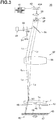
Fig. 2 is a view showing the route of a light beam transmitted through only a non-mark portion on a test lens; -
Fig. 3 is a view showing the route of a light beam transmitted through a mark; -
Fig. 4A is a plan view showing the positional relationship among, e.g., marks on a progressive multifocal lens and its geometric center; -
Fig. 4B is a sectional view taken along a line A - A inFig. 4A ; -
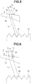
Fig. 5 is a view for explaining mark detection; -
Fig. 6 is a view for explaining another mark detection; -
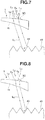
Fig. 7 is a view for explaining still another mark detection; -
Fig. 8 is a view for explaining still another mark detection; -
Fig. 9 is a view for explaining still another mark detection; -
Fig. 10 is a view showing a mark image ; and -
Fig. 11 is a sectional view showing a corner cube prism sheet according to the embodiment of the present invention. - The present invention will be described in detail below with reference to the accompanying drawings.
- An example in which the test lens is a diverging progressive multifocal lens, and hidden marks (to be simply referred to as marks hereinafter) are formed on the convex surface of the lens will be given.
- Referring to
Figs. 4A and 4B ,reference numeral 1 denotes a test lens serving as a plastic progressive multifocal lens with a circular shape (e.g., with a diameter of 80 mm), which has a polished, convexsurface 1a.Reference numeral 2 denotes a horizontal reference line which passes through a geometric center O of thetest lens 1; and 3A, 3B, and 3C, marks respectively formed on theconvex surface 1a. Themarks marks horizontal reference line 2. Themarks number 4 indicating the addition power (the difference in front-side vertex power between a distance portion and a near portion) of thetest lens 1, and an identification mark 5 indicating the type of lens are inscribed in the form of minute projections as well at positions below themarks number 4 indicating the addition power is inscribed as a three-digit number (e.g., 300) at a position below themark 3A positioned on the ear side when one wears the spectacle lens. Hence, whether thetest lens 1 is a left-eye lens or a right-eye lens can be determined by checking whether the three-digit number is inscribed at a position below the left or right mark.Fig. 4 shows a right-eye lens having theleft mark 3A inscribed as a small circle "o", and themark 3B inscribed as an alphabet "H". Themark 3C is a spectacle shop identification mark, is formed in, for example, a round convex shape, and is inscribed on theconvex surface 1a at a position near its outer periphery. - The
test lens 1 serving as a progressive multifocal lens includes a distance power measuring portion 6, a near power measuring portion 7, a portion for distance vision (distance portion) 8, a portion for near vision (near portion) 9, and a portion whose dioptric power continuously changes (progressive portion) 10. - The positions of the distance power measuring portion 6, the near power measuring portion 7, and an
eyepoint 11 of thetest lens 1 change depending on the lens design, and are determined at predetermined reference positions spaced apart from the geometric center O. For example, theeyepoint 11 is at a position spaced apart from the geometric center O to the upper side by a predetermined distance d1 (e.g., 2 mm), and adistance center 12 is at a position spaced apart from the position of theeyepoint 11 to the upper side by a predetermined distance d2 (e.g., 4 mm). Hence, the positions of the geometric center O andeyepoint 11 can be obtained by capturing and processing images of themarks - Referring to
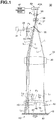
Fig. 1 , a lensimage sensing apparatus 30 includes alight source 31 placed on the side of theconvex surface 1a of thetest lens 1, and anoptical device 32 which guides light beams L emitted by thelight source 31 to thetest lens 1. - The
light source 31 is used to irradiate thetest lens 1 to obtain sharp images of themarks number 4 indicating the addition power, and the identification mark 5, and is a monochromatic point source. The monochromatic point source is a general term including a laser light source that is a point source, and a light source, such as an LED, that can be substantially regarded to be a point source. Note that this exemplifies a red semiconductor laser as the point source. - The
optical device 32 includes acondenser lens 33, transmissionrotary scattering plate 34,half mirror 35, andcollimator lens 36. Thecondenser lens 33 focuses the light beams L emitted by thelight source 31. The transmissionrotary scattering plate 34 is placed in front of thecondenser lens 33. Thehalf mirror 35 guides the light beams L transmitted through the transmissionrotary scattering plate 34 toward thetest lens 1. Thecollimator lens 36 is provided between thehalf mirror 35 and thetest lens 1, and converts the light beams L from thelight source 31 into collimated light beams L1. - The transmission
rotary scattering plate 34 is used to eliminate any speckles and fringes, and serves as a transparent scatterer made of, e.g., glass. The transmissionrotary scattering plate 34 is configured to be rotated by a driving motor (not shown) at the time of measuring the marks on thetest lens 1 so as to scatter the light beams L from thelight source 31. For this reason, the transmissionrotary scattering plate 34 has acoarse surface 34a facing thehalf mirror 35, and is placed at a focal position P1 of thecondenser lens 33. - The
half mirror 35 has an appropriate transmittance and reflectance: it reflects the light beams L, which are emitted by thelight source 31 and transmitted through thecondenser lens 33 and transmissionrotary scattering plate 34, toward thetest lens 1, and transmits light beams L2 and L3 which return from the side of thetest lens 1. - The
collimator lens 36 is arranged in the optical path between thetest lens 1 and thehalf mirror 35. Thecollimator lens 36 converts the light beams L, which are emitted by thelight source 31, transmitted through thecondenser lens 33 and transmissionrotary scattering plate 34, and reflected by thehalf mirror 35, into the collimated light beams L1. - The
test lens 1 is placed at a focal position P2 of thecollimator lens 36 on its lower side. - An
aperture stop 37,bandpass filter 38,re-imaging lens 39,image sensing device 40, andimage processing device 41 are placed on the side of thehalf mirror 35 opposite to that of thetest lens 1. - The
aperture stop 37 is placed at a focal position P3 of thecollimator lens 36 on its upper side, and limits the diameter of the light beam coming from thecollimator lens 36. More specifically, theaperture stop 37 has a diameter which is smaller than that of a light beam from themark 3C on theconvex surface 1a of thetest lens 1, and is larger than that of a light beam from a non-mark portion. However, the position of theaperture stop 37 is not limited to the focal position P3 of thecollimator lens 36. The same function can also be realized by placing theaperture stop 37 at the position of the exit pupil of thecollimator lens 36. - The
bandpass filter 38 serves to transmit only light in the wavelength range of thelight source 31 and cut off ambient light, and is provided between theaperture stop 37 and there-imaging lens 39. - The
re-imaging lens 39 focuses the light beams L2 and L3 having passed through thebandpass filter 38 on theimage sensing device 40. - The
image sensing device 40 includes a plurality ofCCDs 40A which form a light-receiving surface, and is electrically connected to theimage processing device 41. TheCCDs 40A are placed at a focal position P4 of there-imaging lens 39. The focal position P4 of there-imaging lens 39 is conjugate to the position of theconvex surface 1a of thetest lens 1 on the side of thecollimator lens 36. - The lens
image sensing apparatus 30 also includes alens holding device 42 androtary reflector 43 placed on the side of aconcave surface 1b of thetest lens 1. - The
lens holding device 42 serves to chuck and fix the center of theconcave surface 1b of thetest lens 1, and includes atransparent plate 45 and alens chucking cylinder 46 standing upright at the center of the upper surface of thetransparent plate 45. Thelens holding device 42 is configured to chuck and fix the center of theconcave surface 1b of thetest lens 1 on the upper surface of thelens chucking cylinder 46 by evacuating thelens chucking cylinder 46 using a vacuum pump. Thelens chucking cylinder 46 has an outer diameter (e.g., 8 mm) small enough not to hamper projection of themarks number 4 indicating the addition power, and the identification mark 5 on thetest lens 1. - The
rotary reflector 43 serves to retroreflect the light beams L1. transmitted through thetest lens 1 in the same directions as their incident directions, and includes arotary plate 47 and a cornercube prism sheet 48 attached to the surface of therotary plate 47. - The corner
cube prism sheet 48 is made of plastic with a thickness of about 0.3 mm to 0.5 mm, includes a plurality of corner cube prisms (to be also simply referred to as prisms hereinafter) 49 formed on its surface, and is protected by a transparent protective film over the entire surface. Theprisms 49 themselves are conventionally known prisms, which have three orthogonal total reflecting surfaces to have a function of reflecting the collimated light beams L1 transmitted through thetest lens 1 in the same directions as their incident directions, i.e., a retroreflection function. Therotary reflector 43 is configured to be rotated at high speed (e.g., at 3,400 rpm) by a driving motor (not shown) in order to uniform its surface brightness and background, like the transmissionrotary scattering plate 34. - Although the
light source 31 emits innumerable light beams L,Fig. 1 shows only three light beams L scattered by the transmissionrotary scattering plate 34. These scattered light beams L are reflected by thehalf mirror 35, are converted into two collimated light beams L1 and one collimated light beam L2, irradiate themark 3C and two non-mark portions on thetest lens 1, are retroreflected by theprisms 49, and focus on theCCDs 40A of theimage sensing device 40 as four light beams L2 and L3. However, light beams which irradiate other different portions on thetest lens 1 and are transmitted through them similarly focus on theCCDs 40A and form images on them, as a matter of course. - Detection of the
mark 3C on thetest lens 1 by the lensimage sensing apparatus 30 with the above-mentioned arrangement will be described next. - First, the
test lens 1 is provided into the opening in the upper surface of thelens chucking cylinder 46 with theconvex surface 1a facing up. Next, a vacuum exhaust device evacuates thelens chucking cylinder 46 to chuck and fix thetest lens 1 in the opening in the upper surface of thelens chucking cylinder 46. - The
light source 31 is turned on to emit light beams (red laser beams) L. The light beams L emitted by thelight source 31 are focused by thecondenser lens 33. The light beams L are converted into scattered light beams upon being transmitted through the transmissionrotary scattering plate 34. The light beams L strike thehalf mirror 35, are reflected toward thetest lens 1, and are further converted into collimated light beams L1 upon being transmitted through thecollimator lens 36. The collimated light beams L1 become diverging light beams upon being transmitted through thetest lens 1 from theconvex surface 1a to theconcave surface 1b (the collimated light beams L1 become converging light beams when thetest lens 1 is a convex converging dioptric lens). At this time, the collimated light beam L1 which enters thetest lens 1 from a lens surface portion (non-mark portion) other than that where the mark is inscribed strikes theprisms 49, is reflected by theprisms 49 in the same direction as its incident direction to theprisms 49. The light beam L2 is transmitted through thetest lens 1 from theconcave surface 1b, and returns to theconvex surface 1a, as shown inFig. 2 . A reflected light beam L2 diffuses upon being transmitted through thetest lens 1. Nevertheless, because the degree of diffusion of the light beam transmitted through the non-mark portion on theconvex surface 1a is small enough to be ignored, the light beam L2 becomes a retroreflected light beam with a sufficiently small diameter. Thus, the retroreflected light beam L2 passes through theaperture stop 37 with little loss after being transmitted through thecollimator lens 36 again. The retroreflected light beam L2 having passed through theaperture stop 37 is transmitted through thebandpass filter 38 andre-imaging lens 39, and focused on theCCDs 40A of theimage sensing device 40, thereby forming a bright image. - Referring to
Fig. 3 , the collimated light beam L1 transmitted through thecollimator lens 36 strikes and is retroreflected by theprisms 49 upon being transmitted through thetest lens 1, and is transmitted through thetest lens 1 again. At this time, the reflected light beam L3 diffuses upon being transmitted through themark 3C. The degree of diffusion of the reflected light beam L3 is larger than the retroreflected light beam L2 transmitted through the non-mark portion mentioned above. Thus, the light beam L3 transmitted through themark 3C becomes a diverging retroreflected light beam, returns in the same direction as its incident direction, is transmitted through thecollimator lens 36, and passes through theaperture stop 37 with a considerable loss because its diameter is larger than that of theaperture stop 37. The diverging retroreflected light beam L3 is focused on theCCDs 40A of theimage sensing device 40 after being transmitted through thebandpass filter 38 andre-imaging lens 39. This makes it possible to sense a sharp image of themark 3C because the illuminance of themark 3C on theCCDs 40A is lower than the non-mark portion. - The
image sensing device 40 converts the light received by theCCDs 40A into an electrical signal, and sends it to theimage processing device 41. Theimage processing device 41 processes the image information from theimage sensing device 40 to identify a spectacle shop as the delivery destination using themark 3C. Also, theimage sensing device 40 receives the pieces of image information of, e.g., themarks eyepoint 11 based on the pieces of position information of thesemarks - The detection of the
mark 3C will be described in more detail herein with reference toFigs. 5 to 9 . -
Fig. 5 is a view showing the route of a light beam which is transmitted through only the non-mark portion and is not transmitted through themark 3C. Assume that thetest lens 1 is a minus-power lens and theprisms 49 have an appropriate size. In this case, the collimated light beam L1 which enters the non-mark portion on theconvex surface 1a of thetest lens 1 on its periphery is transmitted through thetest lens 1, becomes a diffused light beam, enters thecorner cube prisms 49, and is totally reflected in the same direction as its incident direction by theprisms 49. The reflected light beam L1 enters theconcave surface 1b of thetest lens 1, is transmitted through thetest lens 1 again, and exits the non-mark portion on theconvex surface 1a. An entrance point X1 of the collimated light beam L1 and an exit point X2 of the light beam (retroreflected light beam) L2 which is reflected by theprisms 49 and exits theconvex surface 1a slightly shift from each other in the optical axis direction of thetest lens 1. In this case, because the entrance point X1 and exit point X2 of theconvex surface 1a have nearly the same surface curvature, the light beam L2 which enters and is reflected by theprisms 49 becomes a retroreflected light beam parallel to the collimated light beam L1, and travels back the way it came. The retroreflected light beam L2 is transmitted through thecollimator lens 36,half mirror 35,aperture stop 37,bandpass filter 38, andre-imaging lens 39 shown inFigs. 1 to 3 , and is focused on theCCDs 40A of theimage sensing device 40, thereby forming a bright image. -
Fig. 6 is a view showing the route of a light beam transmitted through themark 3C and the non-mark portion in this order. Because a periphery C of themark 3C has a surface curvature quite different from that of the non-mark portion, the collimated light beam L1 which enters and is transmitted through the periphery C becomes the light beam L3, enters theprisms 49, and is totally reflected in the same direction as its incident direction by theprisms 49. The light beam L3 is transmitted through the non-mark portion on thetest lens 1, exits the non-mark portion from an exit point X3, becomes a light beam parallel to the collimated light beam L1, and travels back the way it came. Note that the light beam L3 is diffused by the periphery C of themark 3C and therefore becomes a diverging retroreflected light beam with a diameter larger than the retroreflected light beam L2 which enters the non-mark portion and exits the non-mark portion, mentioned above. Thus, the diverging retroreflected light beam L3 passes through theaperture stop 37 with a considerable loss, and has an illuminance on theCCDs 40A, that is lower than the non-mark portion, as described above. -
Fig. 7 is a view for explaining the route of a light beam transmitted through the non-mark portion and the periphery of themark 3C in this order. The collimated light beam L1 which enters the non-mark portion on theconvex surface 1a from a point X4 near themark 3C, and is transmitted through the non-mark portion enters theprisms 49, is totally reflected in the same direction as its incident direction by theprisms 49, and exits the periphery C of themark 3C. However, because the periphery C has a surface curvature quite different from that of the non-mark portion, the collimated light beam L1 diffuses into a diverging retroreflected reflected light beam L4 with a large diameter, and exits theconvex surface 1a of thetest lens 1. The diverging retroreflected reflected light beam L4 passes through theaperture stop 37 with a considerable loss, and has an illuminance on theCCDs 40A, that is lower than the non-mark portion, as described above. -
Fig. 8 is a view showing the route of a light beam which enters the central portion of themark 3C, and exits the non-mark portion from a point near themark 3C. The collimated light beam L1 which enters a central portion X5 of themark 3C, and is transmitted through thetest lens 1 enters theprisms 49, is totally reflected in the same direction as its incident direction by theprisms 49, is transmitted through the non-mark portion on thetest lens 1, and exits the non-mark portion from an exit point X6. Because the central portion of the periphery C has a surface curvature close to that of the non-mark portion, the degree of diffusion of the collimated light beam L1 by themark 3C is very small. Thus, the collimated light beam L1 exits theconvex surface 1a of thetest lens 1 from the exit point X6 as a retroreflected light beam L5 with a small diameter. The retroreflected light beam L5 is transmitted through thebandpass filter 38 andre-imaging lens 39, and focused on theCCDs 40A of theimage sensing device 40 without any loss due to factors associated with theaperture stop 37, thereby forming a bright image, like the light beam L2 shown inFigs. 2 and5 . -
Fig. 9 is a view showing the route of a light beam which enters the non-mark portion from a point near themark 3C, is transmitted through the non-mark portion, and exits the central portion of themark 3C upon re-transmission. The collimated light beam L1 which enters the non-mark portion on thetest lens 1 from a point X7 near themark 3C, and is transmitted through thetest lens 1 enters theprisms 49, and is totally reflected in the same direction as its incident direction by theprisms 49. A reflected light beam L6 exits the central portion X5 of themark 3C. Because the central portion X5 of themark 3C has a surface curvature close to that of the non-mark portion on theconvex surface 1a, as described above, the reflected light beam L6 is transmitted through the central portion X5 of themark 3C with little diffusion, and exits theconvex surface 1a of thetest lens 1 from the central portion X5 as a retroreflected light beam with a small diameter. Thus, the reflected light beam L6 is transmitted through thebandpass filter 38 andre-imaging lens 39, and focused on theCCDs 40A without any loss due to factors associated with theaperture stop 37, thereby forming a bright image, like the retroreflected light beams L2 and L5. - That is, in the lens
image sensing apparatus 30, using thecorner cube prisms 49, the light beams L2, L5, and L6 transmitted through only the non-mark portion on theconvex surface 1a in both the forward and backward paths are returned as retroreflected light beams with small degrees of diffusion, and focused on the light-receiving surface of theCCDs 40A. Using thecorner cube prisms 49 as well, the light beams L3 and L4 transmitted through the periphery C of themark 3C in at least one of the forward and backward paths are returned as diverging retroreflected light beams with large degrees of diffusion, and focused on the light-receiving surface of theCCDs 40A. When the retroreflected light beams L2, L5, and L6 and the diverging retroreflected light beams L3 and L4 are guided to theaperture stop 37, the retroreflected light beams L2, L5, and L6 pass through theaperture stop 37 without any losses because they have sufficiently small diameters. Hence, the retroreflected light beams L2, L5, and L6 can generate high illuminances of the mark on the light-receiving surface of theCCDs 40A. In contrast to this, the diverging retroreflected light beams L3 and L4 have diameters larger than that of theaperture stop 37, so they generate low illuminances of the mark on the light-receiving surface of theCCDs 40A because their losses due to factors associated with theaperture stop 37 are large. As a result, the lensimage sensing apparatus 30 can obtain a mark image which is sharper and has a higher contrast than that obtained using the above-mentioned conventional reflective screen. This makes it possible to facilitate image processing, and, in turn, facilitate design of an image processing circuit. -
Fig. 10 is a view showing an image of themark 3C obtained by the apparatus. As shown inFig. 10 , an image of themark 3C formed on theCCDs 40A of theimage sensing device 40 has a dark periphery, a bright central portion, and a clear contour shape, and these features facilitate image processing by theimage processing device 41. - Since the transmission
rotary scattering plate 34 is used, generation of any speckles due to factors associated with the laser light source can be suppressed and prevented. Also, since the brightness of the surface of the cornercube prism sheet 48 in the image background is equalized by therotary reflector 43, image processing can further be facilitated. - Even when the
test lens 1 is a colored lens, it is possible to obtain a sharp image with high contrast as long as the mark has a shape which can obtain retroreflected light and diverging retroreflected light. - Since the
CCDs 40A of theimage sensing device 40 are sufficiently set smaller than thetest lens 1, the ratio between the focal length (f1) of thecollimator lens 36 and the focal length (f2) of the re-imaging lens 39 (their lateral magnification) becomes sufficiently high. This makes it possible to set the longitudinal magnification sufficiently high as well, thus increasing the depth of focus. This has the advantage of minimizing defocusing at the time of observing a thick lens, thus reducing the shadows of the end face of a minus-power lens. - The light beams L emitted by the
light source 31 are converted into the collimated light beams L1 by thecollimator lens 36. However, if the light beams L are not converted into the collimated light beams L1, the exit light from thecollimator lens 36 obliquely enters the end face of thetest lens 1. Therefore, this incident light strikes and is reflected by the edge surface, does not become effective retroreflected light even when it is reflected by theprisms 49, and is not focused on theCCDs 40A of theimage sensing device 40. This makes it impossible to obtain a sharp image. In contrast to this, if the light beams L are converted into the collimated light beams L1, the exit light from thecollimator lens 36 enters the end face of a minus-power lens at a large incident angle. Therefore, this incident light is refracted toward the lens center without striking the edge surface, becomes retroreflected light upon being reflected by theprisms 49 after its transmission through the lens, travels back the way it came, and is focused on theCCDs 40A. This makes it possible to obtain a sharp image. When a conjugate optical system including thecollimator lens 36 andre-imaging lens 39 is designed as a bilateral telecentric optical system, this is preferable because an image with the same barycentric position as an image free from defocusing can be obtained even if defocusing occurs upon fluctuation in thickness of thetest lens 1. - Although image detection of the
convex mark 3C has been described, it is not limited to a convex mark, and a sharp image can also be obtained in the same way even by using a concave mark. That is, because a concave mark is symmetrical to a convex mark and has, on the periphery of its concave portion, a surface curvature quite different from that of theconvex surface 1a of thetest lens 1, light transmitted through the periphery has a large degree of diffusion and therefore becomes diverging retroreflected light, whereas light transmitted through the central portion of the concave portion has a small degree of diffusion and therefore becomes retroreflected light. This makes it possible to obtain a mark image with a clear contour shape and high contrast between the retroreflected light and the diverging retroreflected light. -
Fig. 11 is a sectional view showing a corner cube prism sheet according to the embodiment of the present invention. - In this embodiment, a corner
cube prism sheet 48 is concavely curved on the light source side instead of being formed in a flat shape. Other constituent components in this embodiment are quite the same as the ones shown inFig. 1 . - Assume that the corner
cube prism sheet 48 is formed in a flat shape, as indicated by an alternate long and two short dashed line. In this case, a light beam L1 farther away from the center of atest lens 1 has a larger incident angle α on the surface ofcorner cube prisms 49. Thus, thecorner cube prisms 49 exhibit low reflection efficiency. That is, a large light loss is generated, and this darkens the entire image. This means that a sharp image is hard to obtain when a mark is inscribed on thetest lens 1 near its outer periphery. - To prevent this, the corner
cube prism sheet 48 is concavely curved when viewed from the light source side. Then, the light beam L1 farther away from the center of thetest lens 1 can have an incident angle β on the surface of thecorner cube prisms 49, that is smaller than when the cornercube prism sheet 48 is flat. Thus, thecorner cube prisms 49 exhibit high reflection efficiency, and this makes it possible to reduce a light loss. In this way, a sharp image can be obtained even when a mark inscribed on thetest lens 1 near its outer periphery is used. - If the corner
cube prism sheet 48 has too large a radius of curvature R, it has a shape close to that of a flat plate, and this lessens the effect produced by the cornercube prism sheet 48. If the cornercube prism sheet 48 has too small a radius of curvature R, a light beam which passes through thetest lens 1 near its periphery enters the cornercube prism sheet 48 at a relatively large incident angle, and this generates a light loss. Hence, the cornercube prism sheet 48 is desirably designed to have a preferable value of the radius of curvature R in accordance with the lens dioptric power. If the light beam L1 which enters the convex surface la of thetest lens 1 is a collimated light beam parallel to the optical axis, letting D (diopter) be the dioptric power oftest lens 1, and M be the distance from thetest lens 1 to the cornercube prism sheet 48, the radius of curvature R preferably has a value (R = (-1/D) + M) obtained by adding the distance M to the reciprocal of a negative value of the dioptric power D, or has its neighborhood. Note that if the light beam which enters the convex surface la of thetest lens 1 is not collimated, the radius of curvature R can be set to a value obtained by adding a correction value that depends on the angle of divergence of the incident light beam to the radius of curvature R. - As has been described above, the light source used is a monochromatic point source.
- Also, in the preferred embodiment of the present invention, the corner cube prism sheet is concavely curved when viewed from the light source side to reduce a light loss. That is, when the corner cube prism sheet is flat, light transmitted through the test lens at a position farther away from the center of the test lens more obliquely enters the corner cube prism. This generates a light loss due to factors associated with the prism geometrical structure, and lowers reflection efficiency (the intensity ratio between the incident beam and the outgoing beam). This phenomenon is undesirable because it generates a decrease in image luminance on the outer periphery of the test lens, which exhibits especially high divergence, and deteriorates the detection sensitivity of a mark located near the outer periphery.
- To suppress the influence of the foregoing fact, the corner cube prism sheet is concavely curved when viewed from the light source side. Hence, a light beam which passes through a diverging test lens at a position farther away from its center can have an incident angle on the corner cube prisms, that is smaller than when a flat sheet is used. This makes it possible to keep a light loss small enough to be ignored, and, in turn, makes it possible to sense a sharp image of even a mark inscribed on the test lens near its outer periphery.
- A converging test lens shows a decrease in luminance on its outer periphery less conspicuous than a diverging test lens. In addition, the former lens has a converging optical path from the test lens to the corner cube prism sheet. Thus, even when the corner cube prism sheet is concavely curved, the light beam effective range on the prism sheet is limited to the vicinity of the center of the prism sheet, and the prism sheet has a small tilt angle within the range. For this reason, a decrease in reflectance is kept small enough to be ignored as compared with a case in which the prism sheet has a flat surface.
- If the corner cube prism sheet is undesirably convexly curved when viewed from the light source side, a light beam transmitted through the outer periphery of a diverging test lens enters the corner cube prisms at a large incident angle, and this generates a large light loss and lowers reflection efficiency. This makes it impossible to sense a sharp image of the mark.
- Also, in the preferred embodiment of the present invention, the optical device includes a condenser lens, transmission rotary scattering plate, and half mirror. The condenser lens focuses light emitted by the light source. The transmission rotary scattering plate scatters the light transmitted through the condenser lens. The half mirror guides the light transmitted through the transmission rotary scattering plate to the collimator lens, and further guides, to the aperture stop, the light which is transmitted through the test lens, strikes and is reflected by the rotary reflector, is transmitted through the test lens and collimator lens again, and returns.
- Also, in the preferred embodiment of the present invention, the image sensing device includes a bandpass filter which transmits only light in the wavelength range of the light from the light source.
- Since the bandpass filter transmits only light in the wavelength range of the light from the light source, it is possible to sense an image with high contrast with little influence of ambient light.
- Moreover, in the preferred embodiment of the present invention, the image sensing device includes an image processing device which processes the image sensed by the image sensing device.
Claims (5)
- A lens image sensing apparatus (30) comprising:a light source (31);an optical device (32) including a collimator lens which is configured to convert light emitted by said light source (31) into collimated light, and to guide the collimated light to a convex surface of a test lens;a rotary reflector (43) configured to reflect the light transmitted through the test lens back to the test lens;an image sensing device (40) configured to receive back 11 the light that is reflected by said rotary reflector (43) and transmitted through the test lens and said collimator lens;an aperture stop (37) arranged in an optical path between said collimator lens and said image sensing device (40); anda re-imaging lens (39) provided between said aperture stop (37) and said image sensing device (40),said rotary reflector (43) including a sheet formed from a plurality of corner cube prisms,characterized in that said sheet is concavely curved when viewed from a side of said light source (31) .
- A lens image sensing apparatus (30) according to claim 1, wherein said light source (31) includes a monochromatic point source.
- A lens image sensing apparatus (30) according to claim 1, wherein said optical device (32) further comprises a condenser lens which focuses light emitted by said light source (31), a transmission rotary scattering plate which scatters the light transmitted through said condenser lens, and a half mirror which guides the light transmitted through said transmission rotary scattering plate to said collimator lens, and guides, to said aperture stop (37), the light that is transmitted through the test lens and said collimator lens again and returns.
- A lens image sensing apparatus (30) according to claim 1, wherein said image sensing device (40) comprises a bandpass filter which transmits only light in a wavelength range of the light from said light source (31).
- A lens image sensing apparatus (30) according to claim 1, further comprising an image processing device which processes the image sensed by said image sensing device (40).
Applications Claiming Priority (2)
| Application Number | Priority Date | Filing Date | Title |
|---|---|---|---|
| JP2007334895A JP4906708B2 (en) | 2007-12-26 | 2007-12-26 | Lens imaging device |
| PCT/JP2008/073398 WO2009081928A1 (en) | 2007-12-26 | 2008-12-24 | Image picking-up device for lens |
Publications (3)
| Publication Number | Publication Date |
|---|---|
| EP2239552A1 EP2239552A1 (en) | 2010-10-13 |
| EP2239552A4 EP2239552A4 (en) | 2015-07-08 |
| EP2239552B1 true EP2239552B1 (en) | 2018-09-19 |
Family
ID=40801228
Family Applications (1)
| Application Number | Title | Priority Date | Filing Date |
|---|---|---|---|
| EP08865745.7A Not-in-force EP2239552B1 (en) | 2007-12-26 | 2008-12-24 | Image picking-up device for lens |
Country Status (4)
| Country | Link |
|---|---|
| US (1) | US20100283999A1 (en) |
| EP (1) | EP2239552B1 (en) |
| JP (1) | JP4906708B2 (en) |
| WO (1) | WO2009081928A1 (en) |
Families Citing this family (18)
| Publication number | Priority date | Publication date | Assignee | Title |
|---|---|---|---|---|
| US10259607B2 (en) * | 2008-03-04 | 2019-04-16 | Vanrx Pharmasystems Inc. | Aseptic robotic filling system and method |
| US20130242083A1 (en) * | 2010-10-08 | 2013-09-19 | Timothy A. Potts | Retro-reflective imaging |
| JP5708451B2 (en) * | 2011-11-14 | 2015-04-30 | 株式会社島津製作所 | Sample support jig |
| US10976572B2 (en) | 2011-12-22 | 2021-04-13 | Carl Zeiss Vision International Gmbh | Method for storing information on a spectacles lens, spectacles lens blank or spectacles lens semi-finished product |
| DE102011089704B4 (en) * | 2011-12-22 | 2020-06-18 | Carl Zeiss Vision International Gmbh | Method for storing information on a spectacle lens, glass or plastic body designed as a spectacle lens blank or semi-finished spectacle lens, device for storing information, method for reading out and reading device |
| FR3017964B1 (en) * | 2014-02-27 | 2016-03-25 | Essilor Int | OPTICAL INSTRUMENT FOR RECOVERING AT LEAST ONE CHARACTERISTIC STITCH OF AN OPHTHALMIC LENS |
| FR3017963B1 (en) * | 2014-02-27 | 2016-03-25 | Essilor Int | OPTICAL INSTRUMENT FOR IDENTIFYING AND LOCATING MICROGRAVIDES PRESENTED ON AN OPHTHALMIC LENS |
| CN104931238B (en) * | 2015-05-18 | 2018-03-30 | 京东方科技集团股份有限公司 | A kind of device and method for testing translucent display substrate transparent effect |
| DE102015115735B3 (en) * | 2015-09-17 | 2017-03-23 | Carl Zeiss Vision International Gmbh | Apparatus and method for visualizing a sign on a spectacle lens |
| EP3388813B1 (en) * | 2017-04-13 | 2021-09-29 | Carl Zeiss Vision International GmbH | Method of manufacturing a spectacle lens according to at least one set of shape data |
| CN110146257B (en) * | 2019-05-17 | 2024-02-20 | 中国科学院上海技术物理研究所 | A device and method for quickly measuring changes in the optical axis of space laser loads |
| CN113484322B (en) * | 2021-07-13 | 2023-01-10 | 天津大学 | Optical tweezers super-resolution imaging method and system capable of real-time feedback of axial optical trap position |
| CN114139562B (en) * | 2021-12-08 | 2025-07-01 | 深圳思谋信息科技有限公司 | QR code detection device |
| CN116086776B (en) * | 2023-01-19 | 2026-02-17 | 南京理工大学 | Device and method for detecting divergence angle of collimated light beam |
| KR20240127754A (en) * | 2023-02-16 | 2024-08-23 | 삼성전자주식회사 | Optical measurement apparatus |
| CN118624183B (en) * | 2024-08-09 | 2024-11-12 | 厦门捷能通光电科技有限公司 | A device and method for detecting light loss of lens for lamp beads |
| EP4726373A1 (en) * | 2024-10-10 | 2026-04-15 | Carl Zeiss Jena GmbH | Inspection method, manufacturing method, and inspection system |
| KR102928061B1 (en) | 2025-07-16 | 2026-02-19 | (주) 캔랩 | Lens defect inspection system and method |
Family Cites Families (19)
| Publication number | Priority date | Publication date | Assignee | Title |
|---|---|---|---|---|
| US3375754A (en) * | 1964-09-29 | 1968-04-02 | Bausch & Lomb | Lens testing autocollimator |
| JPS604401B2 (en) * | 1975-01-21 | 1985-02-04 | コニカ株式会社 | interference device |
| JP3404134B2 (en) * | 1994-06-21 | 2003-05-06 | 株式会社ニュークリエイション | Inspection device |
| JP3886619B2 (en) * | 1997-10-16 | 2007-02-28 | 住友化学株式会社 | Object defect inspection method and inspection apparatus |
| US5923425A (en) * | 1997-11-20 | 1999-07-13 | Tropel Corporation | Grazing incidence interferometry for measuring transparent plane-parallel plates |
| DE29901791U1 (en) * | 1999-02-02 | 2000-07-06 | Novartis Ag, Basel | Lens measuring device |
| DE19942998B4 (en) * | 1999-09-09 | 2012-02-09 | Carl Zeiss Jena Gmbh | Microscope for incident and transmitted light microscopy |
| JP2002162655A (en) * | 2000-11-27 | 2002-06-07 | Sony Corp | Optical device |
| CA2413343A1 (en) * | 2002-12-02 | 2004-06-02 | Peter Vokhmin | Method and apparatus for testing optical components |
| FR2853734B1 (en) * | 2003-04-14 | 2005-05-27 | Tecoptique | SYSTEM FOR VISUALIZING OPTICAL MARKINGS OF OPHTHALMIC GLASS, BUFFERING DEVICE AND GLASS ORIENTATION METHOD USING SUCH A SYSTEM |
| DE10333426B4 (en) * | 2003-07-17 | 2006-02-09 | Carl Zeiss | Method and device for visualizing a sign on a spectacle lens |
| WO2005096074A1 (en) * | 2004-03-31 | 2005-10-13 | Kabushiki Kaisha Topcon | Jig mounting device |
| EP1736816B1 (en) * | 2004-03-31 | 2012-06-13 | Topcon Corporation | Device for installing suction jig for eyeglass lens and method for determining suction jig installation position |
| JP4514036B2 (en) * | 2004-10-20 | 2010-07-28 | Hoya株式会社 | Lens imaging device |
| JP4761289B2 (en) * | 2004-11-22 | 2011-08-31 | Hoya株式会社 | Marking apparatus and marking method |
| JP4409467B2 (en) * | 2005-02-08 | 2010-02-03 | 株式会社トプコン | Eyeglass lens suction jig mounting device |
| JP4822318B2 (en) * | 2005-10-18 | 2011-11-24 | 株式会社トプコン | Lens position specifying method and lens suction jig mounting device used for lens suction jig mounting device |
| JP2007252402A (en) * | 2006-03-20 | 2007-10-04 | Topcon Corp | Ophthalmic apparatus |
| JP4970149B2 (en) * | 2007-05-31 | 2012-07-04 | 株式会社ニデック | Cup mounting device |
-
2007
- 2007-12-26 JP JP2007334895A patent/JP4906708B2/en not_active Expired - Fee Related
-
2008
- 2008-12-24 WO PCT/JP2008/073398 patent/WO2009081928A1/en not_active Ceased
- 2008-12-24 US US12/810,144 patent/US20100283999A1/en not_active Abandoned
- 2008-12-24 EP EP08865745.7A patent/EP2239552B1/en not_active Not-in-force
Non-Patent Citations (1)
| Title |
|---|
| None * |
Also Published As
| Publication number | Publication date |
|---|---|
| EP2239552A4 (en) | 2015-07-08 |
| US20100283999A1 (en) | 2010-11-11 |
| JP2009156702A (en) | 2009-07-16 |
| JP4906708B2 (en) | 2012-03-28 |
| EP2239552A1 (en) | 2010-10-13 |
| WO2009081928A1 (en) | 2009-07-02 |
Similar Documents
| Publication | Publication Date | Title |
|---|---|---|
| EP2239552B1 (en) | Image picking-up device for lens | |
| US20110317156A1 (en) | Inspection device for defect inspection | |
| US20040004727A1 (en) | Three-dimensional shape measuring method, and three-dimensional shape measuring apparatus | |
| JPH10501890A (en) | Optical device for determining the position of a reflective target mark | |
| JP3617805B2 (en) | Image pickup processing device for spectacle lens | |
| EP1035408A1 (en) | Apparatus for measuring characteristics of optical angle | |
| US7796276B2 (en) | Apparatus and method for examining a curved surface | |
| JP3221733B2 (en) | Lens measuring device | |
| JPH06100723B2 (en) | Reflective lighting device | |
| JPH0743110A (en) | Two-step detection non-contact positioning device | |
| JP3417736B2 (en) | Optical member inspection device | |
| JPH08254650A (en) | Focus detection device | |
| JP3388285B2 (en) | Inspection device | |
| JP2677351B2 (en) | 3D object external inspection system | |
| JPH08166514A (en) | Oblique lighting system | |
| KR101555542B1 (en) | inspecting machine for flat panel | |
| JP2025508505A (en) | How to measure optical lens surfaces | |
| JP4487042B2 (en) | Optical apparatus, inspection apparatus, and inspection method | |
| JP4514036B2 (en) | Lens imaging device | |
| KR101517097B1 (en) | inspecting machine for flat panel | |
| KR100636505B1 (en) | Optical system lighting device that inspects patterns using Line CCD | |
| JP2000295639A (en) | Illumination device for inspecting solid-state imaging device and adjustment tool used therefor | |
| CN211263958U (en) | High-sensitivity transparent object pulse texture and surface defect observation device | |
| EP1139090A2 (en) | Leaded integrated circuit inspection system | |
| JP3040131B2 (en) | Spherical surface scratch inspection device |
Legal Events
| Date | Code | Title | Description |
|---|---|---|---|
| PUAI | Public reference made under article 153(3) epc to a published international application that has entered the european phase |
Free format text: ORIGINAL CODE: 0009012 |
|
| 17P | Request for examination filed |
Effective date: 20100726 |
|
| AK | Designated contracting states |
Kind code of ref document: A1 Designated state(s): AT BE BG CH CY CZ DE DK EE ES FI FR GB GR HR HU IE IS IT LI LT LU LV MC MT NL NO PL PT RO SE SI SK TR |
|
| AX | Request for extension of the european patent |
Extension state: AL BA MK RS |
|
| DAX | Request for extension of the european patent (deleted) | ||
| REG | Reference to a national code |
Ref country code: DE Ref legal event code: R079 Ref document number: 602008057099 Country of ref document: DE Free format text: PREVIOUS MAIN CLASS: G01M0011000000 Ipc: G01M0011020000 |
|
| RA4 | Supplementary search report drawn up and despatched (corrected) |
Effective date: 20150609 |
|
| RIC1 | Information provided on ipc code assigned before grant |
Ipc: G01N 21/95 20060101ALI20150602BHEP Ipc: G01M 11/02 20060101AFI20150602BHEP Ipc: G01N 21/958 20060101ALI20150602BHEP |
|
| GRAP | Despatch of communication of intention to grant a patent |
Free format text: ORIGINAL CODE: EPIDOSNIGR1 |
|
| INTG | Intention to grant announced |
Effective date: 20180420 |
|
| GRAS | Grant fee paid |
Free format text: ORIGINAL CODE: EPIDOSNIGR3 |
|
| GRAA | (expected) grant |
Free format text: ORIGINAL CODE: 0009210 |
|
| AK | Designated contracting states |
Kind code of ref document: B1 Designated state(s): AT BE BG CH CY CZ DE DK EE ES FI FR GB GR HR HU IE IS IT LI LT LU LV MC MT NL NO PL PT RO SE SI SK TR |
|
| REG | Reference to a national code |
Ref country code: GB Ref legal event code: FG4D |
|
| REG | Reference to a national code |
Ref country code: CH Ref legal event code: EP |
|
| REG | Reference to a national code |
Ref country code: DE Ref legal event code: R096 Ref document number: 602008057099 Country of ref document: DE |
|
| REG | Reference to a national code |
Ref country code: AT Ref legal event code: REF Ref document number: 1043808 Country of ref document: AT Kind code of ref document: T Effective date: 20181015 |
|
| REG | Reference to a national code |
Ref country code: IE Ref legal event code: FG4D |
|
| REG | Reference to a national code |
Ref country code: NL Ref legal event code: MP Effective date: 20180919 |
|
| PG25 | Lapsed in a contracting state [announced via postgrant information from national office to epo] |
Ref country code: GR Free format text: LAPSE BECAUSE OF FAILURE TO SUBMIT A TRANSLATION OF THE DESCRIPTION OR TO PAY THE FEE WITHIN THE PRESCRIBED TIME-LIMIT Effective date: 20181220 Ref country code: FI Free format text: LAPSE BECAUSE OF FAILURE TO SUBMIT A TRANSLATION OF THE DESCRIPTION OR TO PAY THE FEE WITHIN THE PRESCRIBED TIME-LIMIT Effective date: 20180919 Ref country code: SE Free format text: LAPSE BECAUSE OF FAILURE TO SUBMIT A TRANSLATION OF THE DESCRIPTION OR TO PAY THE FEE WITHIN THE PRESCRIBED TIME-LIMIT Effective date: 20180919 Ref country code: NO Free format text: LAPSE BECAUSE OF FAILURE TO SUBMIT A TRANSLATION OF THE DESCRIPTION OR TO PAY THE FEE WITHIN THE PRESCRIBED TIME-LIMIT Effective date: 20181219 Ref country code: BG Free format text: LAPSE BECAUSE OF FAILURE TO SUBMIT A TRANSLATION OF THE DESCRIPTION OR TO PAY THE FEE WITHIN THE PRESCRIBED TIME-LIMIT Effective date: 20181219 Ref country code: LT Free format text: LAPSE BECAUSE OF FAILURE TO SUBMIT A TRANSLATION OF THE DESCRIPTION OR TO PAY THE FEE WITHIN THE PRESCRIBED TIME-LIMIT Effective date: 20180919 |
|
| REG | Reference to a national code |
Ref country code: LT Ref legal event code: MG4D |
|
| PG25 | Lapsed in a contracting state [announced via postgrant information from national office to epo] |
Ref country code: LV Free format text: LAPSE BECAUSE OF FAILURE TO SUBMIT A TRANSLATION OF THE DESCRIPTION OR TO PAY THE FEE WITHIN THE PRESCRIBED TIME-LIMIT Effective date: 20180919 Ref country code: HR Free format text: LAPSE BECAUSE OF FAILURE TO SUBMIT A TRANSLATION OF THE DESCRIPTION OR TO PAY THE FEE WITHIN THE PRESCRIBED TIME-LIMIT Effective date: 20180919 |
|
| REG | Reference to a national code |
Ref country code: AT Ref legal event code: MK05 Ref document number: 1043808 Country of ref document: AT Kind code of ref document: T Effective date: 20180919 |
|
| PG25 | Lapsed in a contracting state [announced via postgrant information from national office to epo] |
Ref country code: ES Free format text: LAPSE BECAUSE OF FAILURE TO SUBMIT A TRANSLATION OF THE DESCRIPTION OR TO PAY THE FEE WITHIN THE PRESCRIBED TIME-LIMIT Effective date: 20180919 Ref country code: IS Free format text: LAPSE BECAUSE OF FAILURE TO SUBMIT A TRANSLATION OF THE DESCRIPTION OR TO PAY THE FEE WITHIN THE PRESCRIBED TIME-LIMIT Effective date: 20190119 Ref country code: PL Free format text: LAPSE BECAUSE OF FAILURE TO SUBMIT A TRANSLATION OF THE DESCRIPTION OR TO PAY THE FEE WITHIN THE PRESCRIBED TIME-LIMIT Effective date: 20180919 Ref country code: IT Free format text: LAPSE BECAUSE OF FAILURE TO SUBMIT A TRANSLATION OF THE DESCRIPTION OR TO PAY THE FEE WITHIN THE PRESCRIBED TIME-LIMIT Effective date: 20180919 Ref country code: CZ Free format text: LAPSE BECAUSE OF FAILURE TO SUBMIT A TRANSLATION OF THE DESCRIPTION OR TO PAY THE FEE WITHIN THE PRESCRIBED TIME-LIMIT Effective date: 20180919 Ref country code: NL Free format text: LAPSE BECAUSE OF FAILURE TO SUBMIT A TRANSLATION OF THE DESCRIPTION OR TO PAY THE FEE WITHIN THE PRESCRIBED TIME-LIMIT Effective date: 20180919 Ref country code: EE Free format text: LAPSE BECAUSE OF FAILURE TO SUBMIT A TRANSLATION OF THE DESCRIPTION OR TO PAY THE FEE WITHIN THE PRESCRIBED TIME-LIMIT Effective date: 20180919 Ref country code: AT Free format text: LAPSE BECAUSE OF FAILURE TO SUBMIT A TRANSLATION OF THE DESCRIPTION OR TO PAY THE FEE WITHIN THE PRESCRIBED TIME-LIMIT Effective date: 20180919 Ref country code: RO Free format text: LAPSE BECAUSE OF FAILURE TO SUBMIT A TRANSLATION OF THE DESCRIPTION OR TO PAY THE FEE WITHIN THE PRESCRIBED TIME-LIMIT Effective date: 20180919 |
|
| PG25 | Lapsed in a contracting state [announced via postgrant information from national office to epo] |
Ref country code: PT Free format text: LAPSE BECAUSE OF FAILURE TO SUBMIT A TRANSLATION OF THE DESCRIPTION OR TO PAY THE FEE WITHIN THE PRESCRIBED TIME-LIMIT Effective date: 20190119 Ref country code: SK Free format text: LAPSE BECAUSE OF FAILURE TO SUBMIT A TRANSLATION OF THE DESCRIPTION OR TO PAY THE FEE WITHIN THE PRESCRIBED TIME-LIMIT Effective date: 20180919 |
|
| REG | Reference to a national code |
Ref country code: DE Ref legal event code: R097 Ref document number: 602008057099 Country of ref document: DE |
|
| REG | Reference to a national code |
Ref country code: DE Ref legal event code: R119 Ref document number: 602008057099 Country of ref document: DE |
|
| PLBE | No opposition filed within time limit |
Free format text: ORIGINAL CODE: 0009261 |
|
| STAA | Information on the status of an ep patent application or granted ep patent |
Free format text: STATUS: NO OPPOSITION FILED WITHIN TIME LIMIT |
|
| PG25 | Lapsed in a contracting state [announced via postgrant information from national office to epo] |
Ref country code: DK Free format text: LAPSE BECAUSE OF FAILURE TO SUBMIT A TRANSLATION OF THE DESCRIPTION OR TO PAY THE FEE WITHIN THE PRESCRIBED TIME-LIMIT Effective date: 20180919 |
|
| REG | Reference to a national code |
Ref country code: CH Ref legal event code: PL |
|
| 26N | No opposition filed |
Effective date: 20190620 |
|
| GBPC | Gb: european patent ceased through non-payment of renewal fee |
Effective date: 20181224 |
|
| PG25 | Lapsed in a contracting state [announced via postgrant information from national office to epo] |
Ref country code: LU Free format text: LAPSE BECAUSE OF NON-PAYMENT OF DUE FEES Effective date: 20181224 Ref country code: MC Free format text: LAPSE BECAUSE OF FAILURE TO SUBMIT A TRANSLATION OF THE DESCRIPTION OR TO PAY THE FEE WITHIN THE PRESCRIBED TIME-LIMIT Effective date: 20180919 |
|
| REG | Reference to a national code |
Ref country code: IE Ref legal event code: MM4A |
|
| REG | Reference to a national code |
Ref country code: BE Ref legal event code: MM Effective date: 20181231 |
|
| PG25 | Lapsed in a contracting state [announced via postgrant information from national office to epo] |
Ref country code: FR Free format text: LAPSE BECAUSE OF NON-PAYMENT OF DUE FEES Effective date: 20181231 Ref country code: IE Free format text: LAPSE BECAUSE OF NON-PAYMENT OF DUE FEES Effective date: 20181224 Ref country code: SI Free format text: LAPSE BECAUSE OF FAILURE TO SUBMIT A TRANSLATION OF THE DESCRIPTION OR TO PAY THE FEE WITHIN THE PRESCRIBED TIME-LIMIT Effective date: 20180919 Ref country code: DE Free format text: LAPSE BECAUSE OF NON-PAYMENT OF DUE FEES Effective date: 20190702 |
|
| PG25 | Lapsed in a contracting state [announced via postgrant information from national office to epo] |
Ref country code: BE Free format text: LAPSE BECAUSE OF NON-PAYMENT OF DUE FEES Effective date: 20181231 |
|
| PG25 | Lapsed in a contracting state [announced via postgrant information from national office to epo] |
Ref country code: LI Free format text: LAPSE BECAUSE OF NON-PAYMENT OF DUE FEES Effective date: 20181231 Ref country code: GB Free format text: LAPSE BECAUSE OF NON-PAYMENT OF DUE FEES Effective date: 20181224 Ref country code: CH Free format text: LAPSE BECAUSE OF NON-PAYMENT OF DUE FEES Effective date: 20181231 |
|
| PG25 | Lapsed in a contracting state [announced via postgrant information from national office to epo] |
Ref country code: MT Free format text: LAPSE BECAUSE OF NON-PAYMENT OF DUE FEES Effective date: 20181224 |
|
| PG25 | Lapsed in a contracting state [announced via postgrant information from national office to epo] |
Ref country code: TR Free format text: LAPSE BECAUSE OF FAILURE TO SUBMIT A TRANSLATION OF THE DESCRIPTION OR TO PAY THE FEE WITHIN THE PRESCRIBED TIME-LIMIT Effective date: 20180919 |
|
| PG25 | Lapsed in a contracting state [announced via postgrant information from national office to epo] |
Ref country code: HU Free format text: LAPSE BECAUSE OF FAILURE TO SUBMIT A TRANSLATION OF THE DESCRIPTION OR TO PAY THE FEE WITHIN THE PRESCRIBED TIME-LIMIT; INVALID AB INITIO Effective date: 20081224 Ref country code: CY Free format text: LAPSE BECAUSE OF FAILURE TO SUBMIT A TRANSLATION OF THE DESCRIPTION OR TO PAY THE FEE WITHIN THE PRESCRIBED TIME-LIMIT Effective date: 20180919 |