EP2238653B1 - Vorrichtung zur befestigung eines flugzeugkabinenmoduls - Google Patents
Vorrichtung zur befestigung eines flugzeugkabinenmoduls Download PDFInfo
- Publication number
- EP2238653B1 EP2238653B1 EP09705325.0A EP09705325A EP2238653B1 EP 2238653 B1 EP2238653 B1 EP 2238653B1 EP 09705325 A EP09705325 A EP 09705325A EP 2238653 B1 EP2238653 B1 EP 2238653B1
- Authority
- EP
- European Patent Office
- Prior art keywords
- aircraft cabin
- plug
- cabin module
- contacts
- locking
- Prior art date
- Legal status (The legal status is an assumption and is not a legal conclusion. Google has not performed a legal analysis and makes no representation as to the accuracy of the status listed.)
- Not-in-force
Links
- QVGXLLKOCUKJST-UHFFFAOYSA-N atomic oxygen Chemical compound [O] QVGXLLKOCUKJST-UHFFFAOYSA-N 0.000 claims description 15
- 229910052760 oxygen Inorganic materials 0.000 claims description 15
- 239000001301 oxygen Substances 0.000 claims description 15
- 230000001133 acceleration Effects 0.000 claims description 8
- 230000001681 protective effect Effects 0.000 claims description 8
- XAGFODPZIPBFFR-UHFFFAOYSA-N aluminium Chemical compound [Al] XAGFODPZIPBFFR-UHFFFAOYSA-N 0.000 claims description 4
- 229910052782 aluminium Inorganic materials 0.000 claims description 4
- 230000007797 corrosion Effects 0.000 claims description 4
- 238000005260 corrosion Methods 0.000 claims description 4
- 239000012777 electrically insulating material Substances 0.000 claims description 4
- 239000004809 Teflon Substances 0.000 claims description 3
- 229920006362 Teflon® Polymers 0.000 claims description 3
- OKTJSMMVPCPJKN-UHFFFAOYSA-N Carbon Chemical compound [C] OKTJSMMVPCPJKN-UHFFFAOYSA-N 0.000 claims 1
- 229920002430 Fibre-reinforced plastic Polymers 0.000 claims 1
- 239000004411 aluminium Substances 0.000 claims 1
- 229910052799 carbon Inorganic materials 0.000 claims 1
- 239000011151 fibre-reinforced plastic Substances 0.000 claims 1
- 238000009434 installation Methods 0.000 description 7
- 239000004918 carbon fiber reinforced polymer Substances 0.000 description 2
- 239000011810 insulating material Substances 0.000 description 2
- 230000005540 biological transmission Effects 0.000 description 1
- 239000003562 lightweight material Substances 0.000 description 1
- 230000035939 shock Effects 0.000 description 1
- 230000001960 triggered effect Effects 0.000 description 1
Images


Classifications
-
- H—ELECTRICITY
- H01—ELECTRIC ELEMENTS
- H01R—ELECTRICALLY-CONDUCTIVE CONNECTIONS; STRUCTURAL ASSOCIATIONS OF A PLURALITY OF MUTUALLY-INSULATED ELECTRICAL CONNECTING ELEMENTS; COUPLING DEVICES; CURRENT COLLECTORS
- H01R13/00—Details of coupling devices of the kinds covered by groups H01R12/70 or H01R24/00 - H01R33/00
- H01R13/62—Means for facilitating engagement or disengagement of coupling parts or for holding them in engagement
- H01R13/627—Snap or like fastening
- H01R13/6275—Latching arms not integral with the housing
-
- H—ELECTRICITY
- H01—ELECTRIC ELEMENTS
- H01R—ELECTRICALLY-CONDUCTIVE CONNECTIONS; STRUCTURAL ASSOCIATIONS OF A PLURALITY OF MUTUALLY-INSULATED ELECTRICAL CONNECTING ELEMENTS; COUPLING DEVICES; CURRENT COLLECTORS
- H01R25/00—Coupling parts adapted for simultaneous co-operation with two or more identical counterparts, e.g. for distributing energy to two or more circuits
- H01R25/14—Rails or bus-bars constructed so that the counterparts can be connected thereto at any point along their length
Definitions
- the invention relates to a device for fastening an aircraft cabin module, which additionally provides the power supply for the aircraft cabin module and allows data exchange between the aircraft cabin module and an aircraft cabin server.
- the DE 10 2006 012 730 B3 describes a fastening system for securing a cabin trim element to a support structure of an aircraft.
- a device is provided for fastening an aircraft cabin module, wherein the device has a component with legs for the releasable locking of a plug attached to the aircraft cabin module and a plurality of electrical contacts.
- the DE 699 36 580 T2 describes an electrical connector with a two-part housing and clamp.
- the electrical connection structure comprises two half shells, each half shell including at least two openings leading from an interior of the half shell to an outer periphery of the half shell.
- Each half-shell includes a recessed channel along an inner surface, with a retaining clip attached to the half-shell that includes at least two pre-bent lugs that pass through the at least two apertures. In this case, the retaining clip is pressed over a snap connection to abut against the inner surface of the half-shell.
- a major surface of the retaining clip rests on the surface of the recessed channel, and prior to connection, the retaining clip in each half shell thereof is supported by a minimum of three contact points is attached, wherein at least two of the contact points are Schnapprivsanbringonne.
- US 2005/211835 A1 and DE 26 08 303 A1 concern a power distribution system.
- the device comprises a component with legs or a U-profile rail for releasably locking a mounted on the seating group connector and a plurality of electrical contacts, wherein the device as a rail component U-shaped is formed, wherein the legs of which have locking points for releasably locking the plug attached to the aircraft cabin module connector and the middle portion connecting the two legs having the electrical contacts for power supply and data exchange with the aircraft cabin module data.
- the contacts are formed by contact grooves that perform a holding function for the plug.
- aircraft cabin modules In the cabin of an aircraft, in particular a passenger aircraft, a plurality of aircraft cabin modules are mounted.
- aircraft cabin modules include, for example, passenger supply units PSU (Passenger Supply Unit), emergency oxygen supply units for decentralized oxygen supply of the passengers in emergency, cabin lighting units, air nozzle units, passenger audio units, for example loudspeakers, or passenger video units, for example display monitors.
- PSU Passenger Supply Unit
- emergency oxygen supply units for decentralized oxygen supply of the passengers in emergency
- cabin lighting units for example, air nozzle units
- passenger audio units for example loudspeakers
- passenger video units for example display monitors.
- Some of these aircraft cabin modules must be supplied with a DC supply voltage of, for example, 28 volts DC, while others, for example the emergency oxygen supply units, must be supplied with an AC voltage of 115 volts AC, for example.
- the aircraft cabin modules are supplied with electrical power via power supply lines which are laid separately from data lines which serve to exchange data between the aircraft cabin modules and a central computer.
- the attachment of the aircraft cabin modules takes place via mechanical brackets, which are mounted in a profile component, which is provided in a cabin supply channel. Due to the separate wiring of data lines and power supply lines, the cost of assembling the aircraft cabin modules within the passenger compartment of an aircraft is high.
- the invention provides a device for fastening at least one aircraft cabin module with the features of patent claim 1.
- the electrical contacts are formed by contact grooves, in which contact pins of the plug attached to the aircraft cabin module plug are displaceable in a longitudinal direction of the rail component before the locking of the plug.
- the rail component consists of a stable, lightweight and electrically insulating material, for example made of aluminum, CFRP and / or
- the electrical contacts with a protective cap to protect against corrosion can be covered.
- the protective cap consists for example of a rubber lip.
- these protective contacts also provide protection against inadvertent contact with the electrically conductive contacts by a fitter or a passenger.
- the electrically conductive contacts comprise contact groups, for example a group of DC contacts for applying a DC voltage, a group of AC contacts for applying an AC voltage, and a group of data contacts for exchanging data between the aircraft cabin modules and an aircraft cabin server.
- the data contacts preferably each have a predetermined characteristic impedance of, for example, 100 ohms / meter.
- spring-mounted locking projections are attached to the plugs, which engage in Arretleitersauslangache.
- this acceleration force is a multiple of the gravitational acceleration force, for example 16 G.
- the fastening device 1 has a U-shaped rail component 2, which preferably consists of a lightweight, stable and insulating material.
- the U-shaped rail component 2 has two opposite legs 2A, 2B, which are connected via a centrally located central portion 2C.
- the two opposite legs 2A, 2B are preferably formed on the central portion 2C.
- the rail component 2 forms a rail profile whose legs form, for example, an angle of about 90 ° to the central portion 2C.
- the light, stable, insulating material of which the rail component 2 consists is, for example, aluminum, CFRP or Teflon.
- the rail component 2 consists for example of a shielding thin aluminum profile. How to get out Fig.
- locking points 3A, 3B are provided on the inner sides of the two opposite legs 2A, 2B.
- the locking points 3A, 3B are preferably opposite each other.
- the locking points 3A, 3B become, for example formed by hemispherical recesses.
- the middle section 2C connecting the two legs 2A, 2B has several electrical contacts 4-1 to 4-11, which are provided on the one hand for supplying power to an aircraft cabin module and on the other hand allow data to be exchanged between an aircraft cabin module and a cabin server.
- the electrical contacts 4-1, 4-2 are provided for applying a DC supply voltage, for example a DC supply voltage of 28 V DC for a normal voltage supply of the aircraft cabin module attached to the fastening device 1.
- contacts 4-3, 4-4 are provided for an emergency DC supply voltage, for example in the amount of 28 volts DC.
- electrical contacts 4-5 to 4-8 also provide data contacts for exchanging data between the mounted aircraft cabin module and an aircraft cabin server.
- these data contacts each have a predetermined characteristic impedance of, for example, 100 ohms / meter.
- the electrical contacts 4-9 to 4-11 are used to apply an AC supply voltage in the amount of, for example, 115 volts AC, which is needed to trigger an emergency oxygen supply for the aircraft cabin.
- fastening device 1 can be installed in a supply channel of an aircraft cabin.
- the electrical contacts 4-i are each provided with an associated protective cap for protection
- This protective cap consists for example of a rubber lip.
- the protective cap also protects against inadvertent touching of the contacts by a fitter or by a passenger.
- the electrical contacts 4-1 to 4-11 as they are in Fig. 1 are shown formed as contact grooves.
- contact grooves contact pins of a plug attached to the aircraft cabin module can be displaced in the longitudinal direction of the rail component before the plug is locked.
- a great flexibility in the assembly of the aircraft cabin modules within the passenger cabin is achieved.
- the installation of the aircraft cabin module for the fitter is significantly facilitated.
- electrical contacts 4-1 to 4-11 are used in a possible embodiment, not only the electrical contact, but also exercise a holding function. This ensures that the aircraft cabin modules are securely attached to the fastening device 1 even with vibrations.
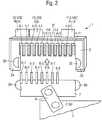
- Fig. 2 shows the mounting of a passenger supply unit 5 to the fastening device 1, as in Fig. 1 is shown.
- the passenger supply unit 5 has a plug 7 attached via a joint 6, the contact pins 8-1 to 8-8 has.
- the distance between the contact pins 8-i corresponds to the distance of the electrical contact 4-i within the rail component 2.
- the height of the protruding contact pins 8-i substantially corresponds to the tie Fe the electrical contact 4-i within the rail component 2. Since the passenger control unit 5 no AC power required, the plug 7 of the passenger supply unit 5 no contact pins for the AC power supply contacts 4-9, 4-10, 4-11.
- the electrical contacts 4-i and the contact pins 8-i are each gold-plated.
- the plug 7 has two opposing spring-loaded locking projections 9A, 9B, which can engage in the Arret istsaus fundamentalungen 3A, 3B of the rail component 2 at locking points.
- the locking projections 9A, 9B are retractable in a housing of the plug 7 against the spring force of a respectively associated spring, wherein the spring force of the attached spring according to the installation specifications is adjustable.
- the spring force of the springs is so high that the locking is triggered only at a very high acceleration force, which is a multiple of the gravitational force.
- the locking is released only at an acceleration of more than sixteen times the gravitational force G.
- the aircraft cabin module 5 can be attached to the fastening device 1 in a very simple manner.
- the aircraft cabin module 5 to be mounted can be displaced in the longitudinal direction of the rail component 2 by the installer, for example to make a fine adjustment.
- the DC power supply contacts 4-1, 4-2 are connected to a DC power source for normal operation.
- the electrical contacts 4-3, 4-4 are connected to a DC power source for emergency operation.
- the data contacts 4-5, 4-6, 4-7, 4-8 are with a server for data exchange with the respective aircraft cabin modules connected.
- the electrical contacts 4-9, 4-10, 4-11 are connected to an AC voltage source which provides, for example, an AC voltage with an amplitude of 115 volts.
- Fig. 3 shows the attachment of an emergency oxygen supply unit 10 to the fastening device 1.
- the emergency oxygen supply unit 10 like the passenger supply unit 5, a plug 7, which is connected via a hinge 6 with the emergency oxygen supply unit 10.
- the emergency oxygen supply unit 10 serves for the decentralized oxygen supply of the passengers in an emergency, oxygen masks falling from the emergency oxygen supply unit 10.
- an AC voltage of, for example, 115 volts AC is needed. Therefore, the electrical connector 7, as in Fig. 3 shown, two contact pins 8-9, 8-11, which engage in corresponding electrical contacts 4-9, 4-11 of the rail component 2.
- the device 1 is used not only for fixing the aircraft cabin modules, but also to their electrical energy supply and data exchange between the aircraft cabin modules and a central processing unit, such as a server.
- the fastening device 1 is suitable for any aircraft cabin modules, for example for passenger supply units, emergency oxygen supply units, cabin lighting units, passenger audio units, passenger video units or air nozzle units.
- the fastening device 1 the Costs are significantly reduced with regard to the wiring. A separate cabling for the energy and data transmission is eliminated.
- the installation of aircraft cabin modules for technicians is greatly facilitated. It a significant improvement in the flexibility in installation of the aircraft cabin modules is achieved. In addition, the maintainability of the aircraft cabin modules is facilitated.
- the fastening device 1 as a standardized interface, it is also possible to integrate novel aircraft cabin modules quickly and easily into the system. Furthermore, the installation of aircraft cabin modules is simplified according to customer requirements.
Landscapes
- Connector Housings Or Holding Contact Members (AREA)
- Details Of Connecting Devices For Male And Female Coupling (AREA)
Description
- Die Erfindung betrifft eine Vorrichtung zur Befestigung eines Flugzeugkabinenmoduls, welches zusätzlich die Spannungsversorgung für das Flugzeugkabinenmodul bereitstellt und einen Datenaustausch zwischen dem Flugzeugkabinenmodul und einem Flugzeugkabinenserver erlaubt.
- Die
DE 10 2006 012 730 B3 beschreibt ein Befestigungssystem zum Befestigen eines Kabinenausstattungselements an einer Trägerstruktur eines Flugzeuges. Es ist eine Vorrichtung zur Befestigung eines Flugzeugkabinenmoduls vorgesehen, wobei die Vorrichtung ein Bauelement mit Schenkeln zur lösbaren Arretierung eines an dem Flugzeugkabinenmodul angebrachten Steckers und mehrere elektrische Kontakte aufweist. - Die
DE 699 36 580 T2 beschreibt einen elektrischen Verbinder mit zweiteiligem Gehäuse und Klemme. Der elektrische Verbindungsaufbau umfasst zwei Halbschalen, wobei jede Halbschale wenigstens zwei Öffnungen einschließt, die von einem Innenraum der Halbschale zu einer äußeren Umgebung der Halbschale führen. Jede Halbschale schließt einen ausgesparten Kanal entlang einer inneren Oberfläche ein, wobei an der Halbschale ein Halteklip angebracht ist, der wenigstens zwei vorgebogene Ansätze einschließt, die durch die mindestens zwei Öffnungen gehen. Dabei ist der Halteklip über eine Schnappverbindung eingepresst, um an der inneren Oberfläche der Halbschale anzuliegen. Eine Hauptoberfläche des Halteklips ruht auf der Oberfläche des ausgesparten Kanals, wobei vor der Verbindung der Halteklip in jeder Halbschale daran durch ein Minimum von drei Kontaktpunkten angebracht ist, wobei wenigstens zwei der Kontaktpunkte Schnappverbindungsanbringungen sind. -
US 2005/211835 A1 undDE 26 08 303 A1 betreffen ein Stromverteilungssystem. Insbesondere beschreibtUS 2005/211835 A1 eine Vorrichtung zur Befestigung mindestens einer Sitzgruppe mit elektrischen Verbrauchern in einer Flugzeugkabine, wobei die Vorrichtung ein Bauelement mit Schenkeln bzw. eine U-Profilschiene zur lösbaren Arretierung eines an der Sitzgruppe angebrachten Steckers und mehrere elektrische Kontakte aufweist, wobei das Bauelement als Schienenbauelement U-förmig ausgebildet ist, wobei dessen Schenkel Arretierungspunkte zur lösbaren Arretierung des an dem Flugzeugskabinenmodul angebrachten Steckers aufweisen und dessen die beiden Schenkel verbindender Mittelabschnitt die elektrische Kontakte zur Spannungsversorgung und zum Datenaustausch von Daten mit dem Flugzeugkabinenmodul aufweist. Die Kontakte sind durch Kontaktnuten gebildet, die eine Haltefunktion für den Stecker ausüben. -
DE 34 16 143 A1 betrifft eine Autobus-Installationsschiene. drei Kontaktpunkten angebracht ist, wobei wenigstens zwei der Kontaktpunkte Schnappverbindungsanbringungen sind. - In der Kabine eines Flugzeuges, insbesondere eines Passagierflugzeuges, sind eine Vielzahl von Flugzeugkabinenmodulen montiert. Diese Flugzeugkabinenmodule umfassen beispielsweise Passagierversorgungseinheiten PSU (Passenger Supply Unit), Notsauerstoffversorgungseinheiten zur dezentralen Sauerstoffversorgung der Passagiere im Notfall, Kabinenbeleuchtungseinheiten, Luftdüseneinheiten, Passagieraudioeinheiten, beispielsweise Lautsprecher, oder Passagiervideoeinheiten, beispielsweise Anzeigemonitore. Einige dieser Flugzeugkabinenmodule müssen mit einer Versorgungsgleichspannung von beispielsweise 28 Volt DC versorgt werden, während andere, beispielsweise die Notsauerstoffversorgungseinheiten, mit einer Wechselspannung von beispielsweise 115 Volt AC versorgt werden müssen.
- Bei herkömmlichen Flugzeugen werden die Flugzeugkabinenmodule über Spannungsversorgungsleitungen mit elektrischer Energie versorgt, die von Datenleitungen, welche zum Austausch von Daten zwischen den Flugzeugkabinenmodulen und einem zentralen Rechner dienen, getrennt verlegt werden.
Die Befestigung der Flugzeugkabinenmodule erfolgt dabei über mechanische Halterungen, die in einem Profilbauelement angebracht sind, das in einem Kabinenversorgungskanal vorgesehen ist.
Aufgrund der getrennten Verkabelung von Datenleitungen und Spannungsversorgungsleitungen ist der Aufwand bei der Montage der Flugzeugkabinenmodule innerhalb des Passagierraumes eines Flugzeuges hoch. - Es ist daher eine Aufgabe der vorliegenden Erfindung, eine Vorrichtung zur Befestigung von Flugzeugkabinenmodulen zu schaffen, bei der der Montageaufwand minimiert wird und die robust gegenüber Erschütterungen und Beschleunigungskräften ist.
- Die Erfindung schafft eine Vorrichtung zur Befestigung mindestens eines Flugzeugkabinenmoduls mit den Merkmalen des Patentanspruchs 1.
- Bei einer Ausführungsform der Vorrichtung werden die elektrischen Kontakte durch Kontaktnuten gebildet, in denen Kontaktstifte des an dem Flugzeugkabinenmodul angebrachten Steckers in einer Längsrichtung des Schienenbauelements vor der Arretierung des Steckers verschiebbar sind.
- Hierdurch wird eine hohe Flexibilität bei der Montage der Flugzeugkabinenmodule erreicht, da ein Monteur vor der Arretierung des Flugzeugkabinenmoduls dieses in Längsrichtung in eine gewünschte Position verschieben kann. Dies ist umso hilfreicher, da die örtliche Verteilung bzw. Positionierung der Flugzeugkabinenmodule in einem Flugzeug entsprechend den Kundenwünschen stark variieren kann. Weiterhin wird es hierdurch einfacher, Plätze für mögliche spätere Einbauten freizuhalten, wenn die Flugzeugkabine beispielsweise ein anderes Bestuhlungs- bzw. Klassen-Layout erhält.
- Bei einer möglichen Ausführungsform besteht das Schienenbauelement aus einem stabilen, leichten und elektrisch isolierenden Material, beispielsweise aus Aluminium, CFK und/oder
- Teflon. In dieses elektrisch isolierende Material werden die elektrisch leitenden Kontakte eingefügt.
- Bei einer Ausführungsform der erfindungsgemäßen Befestigungsvorrichtung sind die elektrischen Kontakte mit einer Schutzkappe zum Schutz gegen Korrosion abdeckbar. Die Schutzkappe besteht dabei beispielsweise aus einer Gummilippe. Neben dem Schutz vor Korrosion bieten diese Schutzkontakte zudem einen Schutz gegen ein unbeabsichtigtes Berühren der elektrisch leitenden Kontakte durch einen Monteur bzw. einen Passagier.
- Die elektrisch leitenden Kontakte weisen bei einer Ausführungsform Kontaktgruppen auf, beispielsweise eine Gruppe von Gleichspannungskontakten zum Anlegen einer Gleichspannung, eine Gruppe von Wechselspannungskontakten zum Anlegen einer Wechselspannung und eine Gruppe von Datenkontakten zum Austausch von Daten zwischen den Flugzeugkabinenmodulen und einem Flugzeugkabinenserver.
- Dabei weisen die Datenkontakte vorzugsweise jeweils einen vorgegebenen Wellenwiderstand von beispielsweise 100 Ohm / Meter auf.
- In einer möglichen Ausführungsform der Befestigungsvorrichtung sind an den Steckern gefederte Arretierungsvorsprünge angebracht, die in Arretierungsausnehmungen einrasten.
- In Abhängigkeit von der Federstärke der an den Arretierungsvorsprüngen angebrachten Feder ist es möglich, die Beschleunigungskräfte abzufangen, bei welcher sich erst Arretierungen im Flugbetrieb lösen können. In einer möglichen Ausführungsform der erfindungsgemäßen Befestigungsvorrichtung beträgt diese Beschleunigungskraft ein Vielfaches der Erdbeschleunigungskraft, beispielsweise 16 G.
- Im Weiteren werden bevorzugte Ausführungsformen der erfindungsgemäßen Befestigungsvorrichtung zur Befestigung eines Flugzeugkabinenmoduls unter Bezugnahme auf die beigefügten Figuren zur Erläuterung erfindungswesentlicher Merkmale beschrieben.
- Es zeigen:
- Fig. 1
- ein Ausführungsbeispiel für eine Befestigungsvorrichtung gemäß der Erfindung;
- Fig. 2
- das Anbringen einer Passagierversorgungseinheit PSU an dem in
Fig. 1 dargestellten Ausführungsbeispiel der Befestigungsvorrichtung gemäß der Erfindung; - Fig. 3
- das Anbringen einer Notsauerstoffversorgungseinheit an der in
Fig. 1 dargestellten Ausführungsbeispiel der Befestigungsvorrichtung gemäß der Erfindung. - Wie man aus
Fig. 1 erkennen kann, weist die Befestigungsvorrichtung 1 ein U-förmig ausgebildetes Schienenbauelement 2 auf, das vorzugsweise aus einem leichten, stabilen und isolierenden Material besteht. Das U-förmig ausgebildete Schienenbauelement 2 weist zwei gegenüberliegende Schenkel 2A, 2B auf, die über einen mittig gelegenen Mittelabschnitt 2C verbunden sind. Die beiden gegenüberliegenden Schenkel 2A, 2B sind an den Mittelabschnitt 2C vorzugsweise angeformt. Das Schienenbauelement 2 bildet ein Schienenprofil, dessen Schenkel beispielsweise einen Winkel von etwa 90° zu dem Mittelabschnitt 2C bilden. Das leichte, stabile, isolierende Material, aus dem das Schienenbauelement 2 besteht, ist beispielsweise Aluminium, CFK oder Teflon. Das Schienenbauelement 2 besteht beispielsweise aus einem abschirmenden
dünnen Aluminiumprofil. Wie man ausFig. 1 erkennen kann, sind an den Innenseiten der beiden gegenüberliegenden Schenkel 2A, 2B jeweils Arretierungspunkte 3A, 3B vorgesehen. Die Arretierungspunkte 3A, 3B liegen vorzugsweise einander gegenüber. Die Arretierungspunkte 3A, 3B werden beispielsweise
durch halbkugelförmige Ausnehmungen gebildet. Der die beiden Schenkel 2A, 2B verbindende Mittelabschnitt 2C weist mehrere elektrische Kontakte 4-1 bis 4-11 auf, die einerseits zur Spannungsversorgung eines Flugzeugkabinenmoduls vorgesehen sind und zum anderen einen Datenaustausch von Daten zwischen einem Flugzeugkabinenmodul und einem Flugkabinenserver ermöglichen. - In dem in
Fig. 1 dargestellten Beispiel sind die elektrischen Kontakte 4-1, 4-2 zum Anlegen einer Versorgungsgleichspannung vorgesehen, beispielsweise einer Versorgungsgleichspannung von 28 Volt DC für eine normale Spannungsversorgung des an der Befestigungsvorrichtung 1 angebrachten Flugzeugkabinenmoduls. - Weiterhin sind die Kontakte 4-3, 4-4 für eine Notfallversorgungsgleichspannung, beispielsweise in Höhe von 28 Volt DC vorgesehen. In dem in
Fig. 1 dargestellt Beispiel bilden ferner die elektrischen Kontakte 4-5 bis 4-8 Datenkontakte, die zum Austausch von Daten zwischen dem befestigten Flugzeugkabinenmodul und einem Flugzeugkabinenserver dienen. Diese Datenkontakte weisen bei einer möglichen Ausführungsform jeweils einen vorgegebenen Wellenwiderstand von beispielsweise 100 Ohm/Meter auf. - Die elektrischen Kontakt 4-9 bis 4-11 dienen zum Anlegen einer Versorgungswechselspannung in Höhe von beispielsweise 115 Volt AC, die zur Auslösung einer Notsauerstoffversorgung für die Flugzeugkabine benötigt wird.
- Die in
Fig. 1 dargestellte Befestigungsvorrichtung 1 kann in einem Versorgungskanal einer Flugzeugkabine verlegt werden. Um Einflüssen durch Feuchtigkeit vorzubeugen, werden bei einer möglichen Ausführungsform die elektrischen Kontakte 4-i jeweils mit einer zugehörigen Schutzkappe zum Schutz gegen - Korrosion abgedeckt. Diese Schutzkappe besteht beispielsweise aus einer Gummilippe. Zusätzlich schützt die Schutzkappe auch gegen ein unbeabsichtigtes Berühren der Kontakte durch einen Monteur oder durch einen Passagier.
- Bei einer möglichen Ausführungsform der erfindungsgemäßen Befestigungsvorrichtung sind die elektrischen Kontakte 4-1 bis 4-11, wie sie in
Fig. 1 dargestellt sind, als Kontaktnuten ausgebildet. In diesen Kontaktnuten sind Kontaktstifte eines an dem Flugzeugkabinenmodul angebrachten Steckers in Längsrichtung des Schienenbauelements vor der Arretierung des Steckers verschiebbar. Hierdurch wird eine große Flexibilität bei der Montage der Flugzeugkabinenmodule innerhalb der Passagierkabine erreicht. Zudem wird die Montage des Flugzeugkabinenmoduls für den Monteur entscheidend erleichtert. Die inFig. 1 dargestellten elektrischen Kontakte 4-1 bis 4-11 dienen bei einer möglichen Ausführungsform nicht nur der elektrischen Kontaktierung, sondern üben zusätzlich eine Haltefunktion aus. Dadurch wird erreicht, dass die Flugzeugkabinenmodule auch bei Vibrationen sicher an der Befestigungsvorrichtung 1 angebracht sind. Zudem wird es für den Monteur leichter, die Flugzeugkabinenmodule vor der letztendlichen Arretierung in Längsrichtung zu verschieben, ohne eine Haltekraft ausüben zu müssen. -
Fig. 2 zeigt die Montage einer Passagierversorgungseinheit 5 an der Befestigungsvorrichtung 1, wie sie inFig. 1 dargestellt ist. In einer möglichen Ausführungsform weist die Passagierversorgungseinheit 5 einen über ein Gelenk 6 angebrachten Stecker 7 auf, der Kontaktstifte 8-1 bis 8-8
besitzt. Der Abstand zwischen den Kontaktstiften 8-i entspricht dem Abstand der elektrischen Kontakt 4-i innerhalb des Schienenbauelements 2. Darüber hinaus entspricht die Höhe der hervorragenden Kontaktstifte 8-i im Wesentlichen der Tie
fe der elektrischen Kontakt 4-i innerhalb des Schienenbauelements 2. Da die Passagierbedieneinheit 5 keine Wechselspannungsversorgung benötigt, weist der Stecker 7 der Passagierversorgungseinheit 5 keine Kontaktstifte für die Wechselspannungsversorgungskontakte 4-9, 4-10, 4-11 auf. In einer möglichen Ausführungsform sind die elektrischen Kontakte 4-i und die Kontaktstifte 8-i jeweils vergoldet. - Wie man aus
Fig. 2 erkennen kann, weist der Stecker 7 zwei einander gegenüberliegende gefederte Arretierungsvorsprünge 9A, 9B auf, welche in die Arretierungsausnehmungen 3A, 3B des Schienenbauelements 2 an Arretierungspunkten einrasten können. Die Arretierungsvorsprünge 9A, 9B sind in einem Gehäuse des Steckers 7 entgegen der Federkraft einer jeweils zugehörigen Feder versenkbar, wobei die Federkraft der angebrachten Feder entsprechend den Montagevorgaben einstellbar ist. Bei einer möglichen Ausführungsform ist die Federkraft der Federn derart hoch, dass die Arretierung erst bei einer sehr hohen Beschleunigungskraft ausgelöst wird, die ein Vielfaches der Erdbeschleunigungskraft beträgt. Bei einer möglichen Ausführungsform wird die Arretierung erst bei einer Beschleunigung von mehr als dem Sechzehnfachen der Erdbeschleunigungskraft G gelöst. - Wie man aus
Fig. 2 erkennen kann, ist das Flugzeugkabinenmodul 5 in sehr einfacher Weise an der Befestigungsvorrichtung 1 anbringbar. Vor der Arretierung, d. h. dem Einrasten der Arretierungsvorsprünge 9A, 9B in entsprechende Arretierungsausnehmungen 3A, 3B kann das zu montierende Flugzeugkabinenmodul 5 in Längsrichtung des Schienenbauelements 2 durch den Monteur verschoben werden, beispielsweise, um eine Feinjustierung vorzunehmen. Die Gleichspannungsversorgungskontakte 4-1, 4-2 sind mit einer Gleichspannungsversorgungsquelle für einen Normalbetrieb verbunden. Die elektrischen Kontakt 4-3, 4-4 sind mit einer Gleichspannungsquelle für den Notfallbetrieb verbunden. Die Datenkontakte 4-5, 4-6, 4-7, 4-8 sind mit einem Server zum Datenaustausch mit den jeweiligen Flugzeugkabinenmodulen verbunden. Die elektrischen Kontakte 4-9, 4-10, 4-11 sind mit einer Wechselspannungsquelle verbunden, die beispielsweise eine Wechselspannung mit einer Amplitude von 115 Volt liefert. -
Fig. 3 zeigt das Anbringen einer Notsauerstoffversorgungseinheit 10 an der Befestigungsvorrichtung 1. Die Notsauerstoffversorgungseinheit 10 weist wie die Passagierversorgungseinheit 5 einen Stecker 7 auf, der über ein Gelenk 6 mit der Notsauerstoffversorgungseinheit 10 verbunden ist. Die Notsauerstoffversorgungseinheit 10 dient zur dezentralen Sauerstoffversorgung der Passagiere im Notfall, wobei Sauerstoffmasken aus der Notsauerstoffversorgungseinheit 10 fallen. Zur Spannungsversorgung der Notsauerstoffversorgungseinheit 10 wird eine Wechselspannung von beispielsweise 115 Volt AC benötigt. Daher weist der elektrische Stecker 7, wie inFig. 3 dargestellt, zwei Kontaktstifte 8-9, 8-11 auf, die in entsprechende elektrische Kontakte 4-9, 4-11 des Schienenbauelements 2 eingreifen. - Wie man aus den
Fig. 1 bis 3 erkennen kann, dient die Vorrichtung 1 nicht nur zur Befestigung der Flugzeugkabinenmodule, sondern auch zu deren elektrischer Energieversorgung sowie dem Datenaustausch zwischen den Flugzeugkabinenmodulen und einer zentralen Recheneinheit, beispielsweise einem Server. Die Befestigungsvorrichtung 1 eignet sich für beliebige Flugzeugkabinenmodule, beispielsweise für Passagierversorgungseinheiten, Notsauerstoffversorgungseinheiten, Kabinenbeleuchtungseinheiten, Passagieraudioeinheiten, Passagiervideoeinheiten oder Luftdüseneinheiten. Mittels der Befestigungsvorrichtung 1 kann der
Aufwand hinsichtlich der Verkabelung erheblich vermindert werden. Eine separate Verkabelung für die Energie- und Datenübertragung entfällt. Weiterhin wird die Montage der Flugzeugkabinenmodule für die Monteure erheblich erleichtert. Es wird eine wesentliche Verbesserung hinsichtlich der Flexibilität beim Einbau der Flugzeugkabinenmodule erreicht. Darüber hinaus wird die Wartbarkeit der Flugzeugkabinenmodule erleichtert. Durch den Einsatz der Befestigungsvorrichtung 1 als standardisierte Schnittstelle ist es zudem möglich, neuartige Flugzeugkabinenmodule schnell und einfach in das System zu integrieren. Weiterhin wird der Einbau von Flugzeugkabinenmodulen entsprechend den Kundenwünschen vereinfacht.
Claims (9)
- Vorrichtung zur Befestigung mindestens eines Flugzeugkabinenmoduls (5, 10),
die ein Bauelement (2) mit Schenkeln (2A, 2B) zur lösbaren Arretierung eines an dem Flugzeugkabinenmodul (5, 10) angebrachten Steckers (7) und mehrere elektrische Kontakte (4-i) aufweist,
wobei
das Bauelement als Schienenbauelement (2) U-förmig ausgebildet ist, wobei dessen Schenkel (2A, 2B) Arretierungspunkte (3A, 3B) zur lösbaren Arretierung des an dem Flugzeugskabinenmodul (5, 10) angebrachten Steckers (7) aufweisen und dessen die beiden Schenkel (2A, 2B) verbindender Mittelabschnitt (2) die elektrische Kontakte (4-i) zur Spannungsversorgung und zum Datenaustausch von Daten mit dem Flugzeugkabinenmodul (5, 10) aufweist,
wobei die Arretierungspunkte (3A, 3B) gebildet sind durch Ausnehmungen,
die derart ausgebildet sind, dass gefederte Arretierungsvorsprünge, die an dem Stecker (7) angebracht sind, in die Ausnehmungen einrasten können, und wobei die elektrischen Kontakte (4-i) durch Kontaktnuten gebildet werden, in denen
Kontaktstifte (8-i) des an dem Flugzeugkabinenmoduls (5, 10) angebrachten Steckers (7) in einer Längsrichtung des Schienenbauelements (2) vor der Arretierung des Steckers (7) verschiebbar sind,
wobei die Kontaktnuten derart ausgebildet sind, dass sie eine Haltefunktion für den Stecker ausüben. - Vorrichtung nach Anspruch 1,
dadurch gekennzeichnet, dass
das Schienenbauelement (2) aus einem elektrisch isolierenden Material besteht, in dem die elektrisch leitenden Kontakte eingefügt sind. - Vorrichtung nach Anspruch 2,
dadurch gekennzeichnet, dass
das elektrisch isolierende Material Aluminium, CFK oder Teflon aufweist. - Vorrichtung nach Anspruch 1-3,
dadurch gekennzeichnet, dass
die elektrischen Kontakte (4-i) jeweils mit einer Schutzkappe zum Schutz gegen Korrosion abdeckbar sind. - Vorrichtung nach Anspruch 4,
dadurch gekennzeichnet, dass
die Schutzkappe eine Gummilippe ist. - Vorrichtung nach Anspruch 1-4,
dadurch gekennzeichnet, dass
die elektrischen Kontakte (4-i)
Gleichspannungskontakte (4-1, 4-2, 4-3, 4-4) zum Anlegen einer Gleichspannung,
Wechselspannungskontakte (4-9, 4-10, 4-11) zum Anlegen einer Wechselspannung und
Datenkontakte (4-5, 4-6, 4-7, 4-8) zum Austausch von Daten zwischen dem Flugzeugkabinenmodul (5, 10) und einem Flugzeugkabinenserver aufweisen. - Anordnung aus einem Flugzeugkabinenmodul und einer Vorrichtung nach Anspruch 1-6,
dadurch gekennzeichnet, dass
das Flugzeugkabinenmodul (5, 10)
eine Passagierversorgungseinheit,
eine Ausgleichseinheit,
eine Notsauerstoffversorgungseinheit,
eine Kabinenbeleuchtungseinheit,
eine Passagieraudioeinheit,
eine Passagiervideoeinheit oder
eine Luftdüseneinheit aufweist. - Vorrichtung nach Anspruch 6,
dadurch gekennzeichnet, dass
die Datenkontakte (4-5, 4-6, 4-7, 4-8) jeweils einen vorgegebenen Wellenwiderstand aufweisen, der 100 Ohm/Meter beträgt oder dem Wellenwiderstand des Verwendeten Datenbusses entspricht. - Anordnung aus einer Vorrichtung nach einem der vorhergehenden Ansprüche und einem Flugzeugkabinenmodul mit einem Stecker mit gefederten Arretierungsvorsprüngen, wobei die lösbare Arretierung des Steckers in dem Schienenbauelement derart ausgebildet ist, dass sich die Arretierung des Flugzeugkabinenmoduls (5; 10) erst bei einer hohen Beschleunigungskraft löst, die mehr als ein Sechzehnfaches der Erdbeschleunigungskraft beträgt.
Applications Claiming Priority (3)
| Application Number | Priority Date | Filing Date | Title |
|---|---|---|---|
| US6258008P | 2008-01-28 | 2008-01-28 | |
| DE102008006433A DE102008006433B4 (de) | 2008-01-28 | 2008-01-28 | Vorrichtung zur Befestigung eines Flugzeugkabinenmoduls |
| PCT/EP2009/050954 WO2009095414A1 (de) | 2008-01-28 | 2009-01-28 | Vorrichtung zur befestigung eines flugzeugkabinenmoduls |
Publications (2)
| Publication Number | Publication Date |
|---|---|
| EP2238653A1 EP2238653A1 (de) | 2010-10-13 |
| EP2238653B1 true EP2238653B1 (de) | 2017-08-02 |
Family
ID=40896405
Family Applications (1)
| Application Number | Title | Priority Date | Filing Date |
|---|---|---|---|
| EP09705325.0A Not-in-force EP2238653B1 (de) | 2008-01-28 | 2009-01-28 | Vorrichtung zur befestigung eines flugzeugkabinenmoduls |
Country Status (9)
| Country | Link |
|---|---|
| US (1) | US9252532B2 (de) |
| EP (1) | EP2238653B1 (de) |
| JP (1) | JP5232249B2 (de) |
| CN (1) | CN101926063A (de) |
| BR (1) | BRPI0906664A2 (de) |
| CA (1) | CA2711246A1 (de) |
| DE (1) | DE102008006433B4 (de) |
| RU (1) | RU2485648C2 (de) |
| WO (1) | WO2009095414A1 (de) |
Families Citing this family (11)
| Publication number | Priority date | Publication date | Assignee | Title |
|---|---|---|---|---|
| US8094436B2 (en) * | 2010-03-29 | 2012-01-10 | Eaton Corporation | Plug-in circuit breaker assembly |
| US8488302B2 (en) | 2011-04-14 | 2013-07-16 | Eaton Corporation | Circuit breaker panel |
| US8776145B2 (en) | 2011-09-16 | 2014-07-08 | Elwha Llc | In-transit electronic media with location-based content |
| US9158908B2 (en) | 2011-09-16 | 2015-10-13 | Elwha Llc | Power source for in-transit electronic media |
| US8649160B2 (en) | 2012-02-07 | 2014-02-11 | Eaton Corporation | Plug-in circuit breaker assembly including insulative retainers |
| CN103523216B (zh) * | 2013-07-10 | 2016-02-03 | 西安航空制动科技有限公司 | 碳-碳复合材料导轨及其制备方法 |
| CN106463855B (zh) * | 2014-06-13 | 2020-10-16 | 3M创新有限公司 | 电连接器 |
| EP3410143B1 (de) * | 2017-05-31 | 2019-07-10 | Siemens Healthcare GmbH | Steckverbindung zum einsatz in einem magnetresonanzgerät |
| US12266893B2 (en) * | 2022-04-19 | 2025-04-01 | Dell Products L.P. | Connection assembly for use in an information handling system |
| DE102022124324A1 (de) * | 2022-09-22 | 2024-03-28 | Te Connectivity Germany Gmbh | Gehäuseanordnung für einen elektrischen Stecker sowie elektrischer Stecker und Steckeranordnung |
| US12431666B2 (en) * | 2022-12-30 | 2025-09-30 | Roku, Inc. | Expandable accordion-style cable overmold for secure connection |
Family Cites Families (33)
| Publication number | Priority date | Publication date | Assignee | Title |
|---|---|---|---|---|
| US3566336A (en) * | 1968-08-30 | 1971-02-23 | Itt | Connector assembly |
| IT1033395B (it) * | 1975-03-04 | 1979-07-10 | Gc Illumination Spa | Canale elettrificato con connettore ad innesto a scatto |
| US4458973A (en) * | 1983-01-28 | 1984-07-10 | Amp Incorporated | Connector assembly having improved internal latching system |
| DE3416143A1 (de) * | 1984-05-02 | 1985-11-07 | Sidler GmbH & Co, 7400 Tübingen | Autobus-installationsschiene |
| US4572602A (en) * | 1984-10-31 | 1986-02-25 | Amp Incorporated | Electrical connector assembly with guide member |
| US4761144A (en) * | 1986-12-22 | 1988-08-02 | Amp Incorporated | Mounting means for rack and panel connector |
| NL9000967A (nl) * | 1990-04-23 | 1991-11-18 | Du Pont Nederland | Inrichting voor elektro-optische signaalconversie. |
| US5486117A (en) * | 1994-08-09 | 1996-01-23 | Molex Incorporated | Locking system for an electrical connector assembly |
| US5575690A (en) * | 1994-10-28 | 1996-11-19 | Tvm, Inc. | Hybrid modular electrical connector system |
| JP3000336B2 (ja) * | 1995-06-02 | 2000-01-17 | 日本航空電子工業株式会社 | コネクタ装置 |
| JP3232240B2 (ja) * | 1996-04-26 | 2001-11-26 | ヒロセ電機株式会社 | 電気コネクタ |
| JP3143739B2 (ja) * | 1997-10-06 | 2001-03-07 | 日本航空電子工業株式会社 | フローティング機能を有するコネクタ装置 |
| US6244889B1 (en) * | 1998-01-20 | 2001-06-12 | Intel Corporation | Method and apparatus for an electromechanically controlled electronic interface plug |
| KR100413026B1 (ko) * | 1998-04-30 | 2004-03-22 | 삼성전자주식회사 | 커넥터어셈블리 |
| WO1999062145A1 (en) * | 1998-05-27 | 1999-12-02 | Tyco Electronics Corporation | Electrical connector with split shells and retention clip and method of assembling the connector |
| CN1204659C (zh) * | 1999-01-26 | 2005-06-01 | 莫列斯公司 | 带有锁合机构和金属弹簧的电连接器 |
| DE29904381U1 (de) * | 1999-03-10 | 2000-08-10 | Robert Bosch Gmbh, 70469 Stuttgart | Elektrische Steckvorrichtung mit einer Fixiereinrichtung |
| US6123575A (en) * | 1999-07-30 | 2000-09-26 | Huang; Wayne | Electrical card connector with mixed latching means |
| US6687780B1 (en) * | 2000-11-02 | 2004-02-03 | Rambus Inc. | Expandable slave device system |
| JP2003303634A (ja) * | 2002-04-11 | 2003-10-24 | Tyco Electronics Amp Kk | 電気コネクタ組立体およびキャップコネクタ |
| US6945666B2 (en) * | 2003-06-30 | 2005-09-20 | Monarch Instrument | Illumination device with removable power pack |
| CN2652608Y (zh) * | 2003-11-06 | 2004-11-03 | 韩金龙 | 锁紧式刀库 |
| JP4193723B2 (ja) * | 2004-02-13 | 2008-12-10 | 住友電装株式会社 | コネクタ |
| US7188805B2 (en) * | 2004-03-27 | 2007-03-13 | The Boeing Company | Continuous power bus for seat power |
| US7060910B2 (en) * | 2004-08-18 | 2006-06-13 | Airbus Deutschland Gmbh | Attachment system for an electrical device for installation in aircraft cabins |
| US7217146B2 (en) * | 2004-12-17 | 2007-05-15 | Scientific-Atlanta, Inc. | Connector insert for preventing contamination |
| FR2881278A1 (fr) * | 2005-01-21 | 2006-07-28 | Fci Sa | Connecteur electrique pourvu d'un capot reversible de guidage de cables, et procede d'assemblage d'un tel connecteur |
| CN2850045Y (zh) * | 2005-04-08 | 2006-12-20 | 富士康(昆山)电脑接插件有限公司 | 电连接器组件 |
| JP2007122886A (ja) * | 2005-10-25 | 2007-05-17 | Fujitsu Component Ltd | コネクタ保護カバー |
| DE102006012730B3 (de) * | 2006-03-17 | 2007-11-08 | Airbus Deutschland Gmbh | Befestigungssystem zum Befestigen eines Kabinenausstattungselements an einer Trägerstruktur eines Flugzeugs |
| US7431605B2 (en) * | 2006-12-06 | 2008-10-07 | J.S.T. Corporation | Connector position assurance apparatus |
| AU314482S (en) * | 2007-03-14 | 2007-06-08 | Tyco Electronics Services Gmbh | Dust cover for an electrical connector |
| CN101677168B (zh) * | 2008-09-16 | 2011-09-07 | 富士康(昆山)电脑接插件有限公司 | 电连接器组件及其插座电连接器与插头电连接器 |
-
2008
- 2008-01-28 DE DE102008006433A patent/DE102008006433B4/de not_active Expired - Fee Related
-
2009
- 2009-01-28 CA CA2711246A patent/CA2711246A1/en not_active Abandoned
- 2009-01-28 JP JP2010543525A patent/JP5232249B2/ja not_active Expired - Fee Related
- 2009-01-28 CN CN200980103879XA patent/CN101926063A/zh active Pending
- 2009-01-28 RU RU2010133887/07A patent/RU2485648C2/ru not_active IP Right Cessation
- 2009-01-28 EP EP09705325.0A patent/EP2238653B1/de not_active Not-in-force
- 2009-01-28 WO PCT/EP2009/050954 patent/WO2009095414A1/de not_active Ceased
- 2009-01-28 BR BRPI0906664-0A patent/BRPI0906664A2/pt not_active IP Right Cessation
-
2010
- 2010-07-14 US US12/836,282 patent/US9252532B2/en active Active
Non-Patent Citations (1)
| Title |
|---|
| None * |
Also Published As
| Publication number | Publication date |
|---|---|
| US20110034058A1 (en) | 2011-02-10 |
| CA2711246A1 (en) | 2009-08-06 |
| RU2010133887A (ru) | 2012-03-10 |
| DE102008006433B4 (de) | 2011-07-28 |
| RU2485648C2 (ru) | 2013-06-20 |
| US9252532B2 (en) | 2016-02-02 |
| BRPI0906664A2 (pt) | 2015-07-14 |
| EP2238653A1 (de) | 2010-10-13 |
| JP5232249B2 (ja) | 2013-07-10 |
| JP2011513891A (ja) | 2011-04-28 |
| DE102008006433A1 (de) | 2009-08-27 |
| CN101926063A (zh) | 2010-12-22 |
| WO2009095414A1 (de) | 2009-08-06 |
Similar Documents
| Publication | Publication Date | Title |
|---|---|---|
| DE102008006433B4 (de) | Vorrichtung zur Befestigung eines Flugzeugkabinenmoduls | |
| DE102009058849A1 (de) | Systemkomponentenmodul und Verfahren zur Montage eines Systemkomponentenmoduls | |
| EP1626470B1 (de) | Stromverteilungssystem zur elektrischen Versorgung von schienenmontierten Einbauten in einem Flugzeug | |
| EP2121440A1 (de) | Anordnung zumindest einer personal service unit in einem fahrzeug | |
| DE102018127019B4 (de) | Elektrisches Verbindungssystem für einen Sitz | |
| DE102020101867A1 (de) | Batteriesystem für ein elektrisch betreibbares Fahrzeug | |
| DE102010048096A1 (de) | Befestigungssystem | |
| DE112015005781T5 (de) | Kraftfahrzeug-Stromversorgungsvorrichtung | |
| EP2406115B1 (de) | Deckenpanel mit vorhangschiene in einer transportmittelkabine, verfahren und verwendung | |
| DE10304278A1 (de) | Struktur zur Befestigung einer zentralen Anzeigeeinheit | |
| DE68913364T2 (de) | Modulare Dachverkleidung mit einer elektrischen Verkabelung. | |
| DE112006002426T5 (de) | Energiekabel-Schutzsystem für geparkte Flugzeuge | |
| EP3833599B1 (de) | Anordnung mit elektronikgehäuse für flugzeuge | |
| EP2451707B1 (de) | Verfahren zur reduzierung der einbauzeit einer versorgungskanaleinheit | |
| DE602005000133T2 (de) | Versorgungsrückleitungsvorrichtung für Bordelektronikeinrichtungen | |
| DE102010055962A1 (de) | Flugzeugsystemkomponententrägermodul und -system sowie Montageverfahren | |
| DE102010055995A1 (de) | Flugzeugsystemkomponententrägersystem und Montageverfahren | |
| WO2020193805A1 (de) | Batterieanordnung | |
| DE102022115942A1 (de) | Sockelleistenvorrichtung für eine Elektroinstallation | |
| DE102007062193A1 (de) | Vorrichtung zur Aufnahme von Leitungen in einem Flugzeug | |
| DE102020206618A1 (de) | Elektrische schnittstellenanordnung | |
| DE102022004429B4 (de) | Halteplatte | |
| EP3772788A1 (de) | Befestigungselement und befestigungssystem | |
| DE102013015957A1 (de) | Leitungssatz und Leitungssatzbaukasten | |
| DE202014004364U1 (de) | Optisches Überwachungssystem für ein Schienenfahrzeug |
Legal Events
| Date | Code | Title | Description |
|---|---|---|---|
| PUAI | Public reference made under article 153(3) epc to a published international application that has entered the european phase |
Free format text: ORIGINAL CODE: 0009012 |
|
| 17P | Request for examination filed |
Effective date: 20100629 |
|
| AK | Designated contracting states |
Kind code of ref document: A1 Designated state(s): AT BE BG CH CY CZ DE DK EE ES FI FR GB GR HR HU IE IS IT LI LT LU LV MC MK MT NL NO PL PT RO SE SI SK TR |
|
| AX | Request for extension of the european patent |
Extension state: AL BA RS |
|
| DAX | Request for extension of the european patent (deleted) | ||
| 17Q | First examination report despatched |
Effective date: 20160616 |
|
| RAP1 | Party data changed (applicant data changed or rights of an application transferred) |
Owner name: AIRBUS OPERATIONS GMBH |
|
| GRAP | Despatch of communication of intention to grant a patent |
Free format text: ORIGINAL CODE: EPIDOSNIGR1 |
|
| STAA | Information on the status of an ep patent application or granted ep patent |
Free format text: STATUS: GRANT OF PATENT IS INTENDED |
|
| INTG | Intention to grant announced |
Effective date: 20170330 |
|
| GRAS | Grant fee paid |
Free format text: ORIGINAL CODE: EPIDOSNIGR3 |
|
| GRAA | (expected) grant |
Free format text: ORIGINAL CODE: 0009210 |
|
| STAA | Information on the status of an ep patent application or granted ep patent |
Free format text: STATUS: THE PATENT HAS BEEN GRANTED |
|
| AK | Designated contracting states |
Kind code of ref document: B1 Designated state(s): AT BE BG CH CY CZ DE DK EE ES FI FR GB GR HR HU IE IS IT LI LT LU LV MC MK MT NL NO PL PT RO SE SI SK TR |
|
| REG | Reference to a national code |
Ref country code: GB Ref legal event code: FG4D Free format text: NOT ENGLISH |
|
| REG | Reference to a national code |
Ref country code: CH Ref legal event code: EP Ref country code: AT Ref legal event code: REF Ref document number: 915429 Country of ref document: AT Kind code of ref document: T Effective date: 20170815 |
|
| REG | Reference to a national code |
Ref country code: IE Ref legal event code: FG4D Free format text: LANGUAGE OF EP DOCUMENT: GERMAN |
|
| REG | Reference to a national code |
Ref country code: DE Ref legal event code: R096 Ref document number: 502009014211 Country of ref document: DE |
|
| REG | Reference to a national code |
Ref country code: NL Ref legal event code: MP Effective date: 20170802 |
|
| REG | Reference to a national code |
Ref country code: LT Ref legal event code: MG4D |
|
| REG | Reference to a national code |
Ref country code: FR Ref legal event code: PLFP Year of fee payment: 10 |
|
| PG25 | Lapsed in a contracting state [announced via postgrant information from national office to epo] |
Ref country code: NO Free format text: LAPSE BECAUSE OF FAILURE TO SUBMIT A TRANSLATION OF THE DESCRIPTION OR TO PAY THE FEE WITHIN THE PRESCRIBED TIME-LIMIT Effective date: 20171102 Ref country code: LT Free format text: LAPSE BECAUSE OF FAILURE TO SUBMIT A TRANSLATION OF THE DESCRIPTION OR TO PAY THE FEE WITHIN THE PRESCRIBED TIME-LIMIT Effective date: 20170802 Ref country code: SE Free format text: LAPSE BECAUSE OF FAILURE TO SUBMIT A TRANSLATION OF THE DESCRIPTION OR TO PAY THE FEE WITHIN THE PRESCRIBED TIME-LIMIT Effective date: 20170802 Ref country code: HR Free format text: LAPSE BECAUSE OF FAILURE TO SUBMIT A TRANSLATION OF THE DESCRIPTION OR TO PAY THE FEE WITHIN THE PRESCRIBED TIME-LIMIT Effective date: 20170802 Ref country code: NL Free format text: LAPSE BECAUSE OF FAILURE TO SUBMIT A TRANSLATION OF THE DESCRIPTION OR TO PAY THE FEE WITHIN THE PRESCRIBED TIME-LIMIT Effective date: 20170802 Ref country code: FI Free format text: LAPSE BECAUSE OF FAILURE TO SUBMIT A TRANSLATION OF THE DESCRIPTION OR TO PAY THE FEE WITHIN THE PRESCRIBED TIME-LIMIT Effective date: 20170802 |
|
| PG25 | Lapsed in a contracting state [announced via postgrant information from national office to epo] |
Ref country code: IS Free format text: LAPSE BECAUSE OF FAILURE TO SUBMIT A TRANSLATION OF THE DESCRIPTION OR TO PAY THE FEE WITHIN THE PRESCRIBED TIME-LIMIT Effective date: 20171202 Ref country code: BG Free format text: LAPSE BECAUSE OF FAILURE TO SUBMIT A TRANSLATION OF THE DESCRIPTION OR TO PAY THE FEE WITHIN THE PRESCRIBED TIME-LIMIT Effective date: 20171102 Ref country code: LV Free format text: LAPSE BECAUSE OF FAILURE TO SUBMIT A TRANSLATION OF THE DESCRIPTION OR TO PAY THE FEE WITHIN THE PRESCRIBED TIME-LIMIT Effective date: 20170802 Ref country code: GR Free format text: LAPSE BECAUSE OF FAILURE TO SUBMIT A TRANSLATION OF THE DESCRIPTION OR TO PAY THE FEE WITHIN THE PRESCRIBED TIME-LIMIT Effective date: 20171103 Ref country code: ES Free format text: LAPSE BECAUSE OF FAILURE TO SUBMIT A TRANSLATION OF THE DESCRIPTION OR TO PAY THE FEE WITHIN THE PRESCRIBED TIME-LIMIT Effective date: 20170802 Ref country code: PL Free format text: LAPSE BECAUSE OF FAILURE TO SUBMIT A TRANSLATION OF THE DESCRIPTION OR TO PAY THE FEE WITHIN THE PRESCRIBED TIME-LIMIT Effective date: 20170802 |
|
| PG25 | Lapsed in a contracting state [announced via postgrant information from national office to epo] |
Ref country code: RO Free format text: LAPSE BECAUSE OF FAILURE TO SUBMIT A TRANSLATION OF THE DESCRIPTION OR TO PAY THE FEE WITHIN THE PRESCRIBED TIME-LIMIT Effective date: 20170802 Ref country code: DK Free format text: LAPSE BECAUSE OF FAILURE TO SUBMIT A TRANSLATION OF THE DESCRIPTION OR TO PAY THE FEE WITHIN THE PRESCRIBED TIME-LIMIT Effective date: 20170802 Ref country code: CZ Free format text: LAPSE BECAUSE OF FAILURE TO SUBMIT A TRANSLATION OF THE DESCRIPTION OR TO PAY THE FEE WITHIN THE PRESCRIBED TIME-LIMIT Effective date: 20170802 |
|
| REG | Reference to a national code |
Ref country code: DE Ref legal event code: R097 Ref document number: 502009014211 Country of ref document: DE |
|
| PG25 | Lapsed in a contracting state [announced via postgrant information from national office to epo] |
Ref country code: IT Free format text: LAPSE BECAUSE OF FAILURE TO SUBMIT A TRANSLATION OF THE DESCRIPTION OR TO PAY THE FEE WITHIN THE PRESCRIBED TIME-LIMIT Effective date: 20170802 Ref country code: SK Free format text: LAPSE BECAUSE OF FAILURE TO SUBMIT A TRANSLATION OF THE DESCRIPTION OR TO PAY THE FEE WITHIN THE PRESCRIBED TIME-LIMIT Effective date: 20170802 Ref country code: EE Free format text: LAPSE BECAUSE OF FAILURE TO SUBMIT A TRANSLATION OF THE DESCRIPTION OR TO PAY THE FEE WITHIN THE PRESCRIBED TIME-LIMIT Effective date: 20170802 |
|
| PLBE | No opposition filed within time limit |
Free format text: ORIGINAL CODE: 0009261 |
|
| STAA | Information on the status of an ep patent application or granted ep patent |
Free format text: STATUS: NO OPPOSITION FILED WITHIN TIME LIMIT |
|
| 26N | No opposition filed |
Effective date: 20180503 |
|
| REG | Reference to a national code |
Ref country code: DE Ref legal event code: R119 Ref document number: 502009014211 Country of ref document: DE |
|
| PG25 | Lapsed in a contracting state [announced via postgrant information from national office to epo] |
Ref country code: SI Free format text: LAPSE BECAUSE OF FAILURE TO SUBMIT A TRANSLATION OF THE DESCRIPTION OR TO PAY THE FEE WITHIN THE PRESCRIBED TIME-LIMIT Effective date: 20170802 |
|
| REG | Reference to a national code |
Ref country code: CH Ref legal event code: PL |
|
| GBPC | Gb: european patent ceased through non-payment of renewal fee |
Effective date: 20180128 |
|
| PG25 | Lapsed in a contracting state [announced via postgrant information from national office to epo] |
Ref country code: MT Free format text: LAPSE BECAUSE OF FAILURE TO SUBMIT A TRANSLATION OF THE DESCRIPTION OR TO PAY THE FEE WITHIN THE PRESCRIBED TIME-LIMIT Effective date: 20170802 |
|
| PG25 | Lapsed in a contracting state [announced via postgrant information from national office to epo] |
Ref country code: DE Free format text: LAPSE BECAUSE OF NON-PAYMENT OF DUE FEES Effective date: 20180801 Ref country code: LU Free format text: LAPSE BECAUSE OF NON-PAYMENT OF DUE FEES Effective date: 20180128 |
|
| REG | Reference to a national code |
Ref country code: IE Ref legal event code: MM4A |
|
| REG | Reference to a national code |
Ref country code: BE Ref legal event code: MM Effective date: 20180131 |
|
| PG25 | Lapsed in a contracting state [announced via postgrant information from national office to epo] |
Ref country code: LI Free format text: LAPSE BECAUSE OF NON-PAYMENT OF DUE FEES Effective date: 20180131 Ref country code: CH Free format text: LAPSE BECAUSE OF NON-PAYMENT OF DUE FEES Effective date: 20180131 Ref country code: BE Free format text: LAPSE BECAUSE OF NON-PAYMENT OF DUE FEES Effective date: 20180131 Ref country code: GB Free format text: LAPSE BECAUSE OF NON-PAYMENT OF DUE FEES Effective date: 20180128 |
|
| PG25 | Lapsed in a contracting state [announced via postgrant information from national office to epo] |
Ref country code: IE Free format text: LAPSE BECAUSE OF NON-PAYMENT OF DUE FEES Effective date: 20180128 |
|
| REG | Reference to a national code |
Ref country code: AT Ref legal event code: MM01 Ref document number: 915429 Country of ref document: AT Kind code of ref document: T Effective date: 20180128 |
|
| PG25 | Lapsed in a contracting state [announced via postgrant information from national office to epo] |
Ref country code: AT Free format text: LAPSE BECAUSE OF NON-PAYMENT OF DUE FEES Effective date: 20180128 |
|
| PG25 | Lapsed in a contracting state [announced via postgrant information from national office to epo] |
Ref country code: MC Free format text: LAPSE BECAUSE OF FAILURE TO SUBMIT A TRANSLATION OF THE DESCRIPTION OR TO PAY THE FEE WITHIN THE PRESCRIBED TIME-LIMIT Effective date: 20170802 |
|
| PG25 | Lapsed in a contracting state [announced via postgrant information from national office to epo] |
Ref country code: TR Free format text: LAPSE BECAUSE OF FAILURE TO SUBMIT A TRANSLATION OF THE DESCRIPTION OR TO PAY THE FEE WITHIN THE PRESCRIBED TIME-LIMIT Effective date: 20170802 |
|
| PG25 | Lapsed in a contracting state [announced via postgrant information from national office to epo] |
Ref country code: PT Free format text: LAPSE BECAUSE OF FAILURE TO SUBMIT A TRANSLATION OF THE DESCRIPTION OR TO PAY THE FEE WITHIN THE PRESCRIBED TIME-LIMIT Effective date: 20170802 Ref country code: HU Free format text: LAPSE BECAUSE OF FAILURE TO SUBMIT A TRANSLATION OF THE DESCRIPTION OR TO PAY THE FEE WITHIN THE PRESCRIBED TIME-LIMIT; INVALID AB INITIO Effective date: 20090128 |
|
| PG25 | Lapsed in a contracting state [announced via postgrant information from national office to epo] |
Ref country code: MK Free format text: LAPSE BECAUSE OF NON-PAYMENT OF DUE FEES Effective date: 20170802 Ref country code: CY Free format text: LAPSE BECAUSE OF FAILURE TO SUBMIT A TRANSLATION OF THE DESCRIPTION OR TO PAY THE FEE WITHIN THE PRESCRIBED TIME-LIMIT Effective date: 20170802 |
|
| PGFP | Annual fee paid to national office [announced via postgrant information from national office to epo] |
Ref country code: FR Payment date: 20200121 Year of fee payment: 12 |
|
| PG25 | Lapsed in a contracting state [announced via postgrant information from national office to epo] |
Ref country code: FR Free format text: LAPSE BECAUSE OF NON-PAYMENT OF DUE FEES Effective date: 20210131 |