EP2237823B1 - Medicine ejection apparatus and control method thereof - Google Patents
Medicine ejection apparatus and control method thereof Download PDFInfo
- Publication number
- EP2237823B1 EP2237823B1 EP09703630A EP09703630A EP2237823B1 EP 2237823 B1 EP2237823 B1 EP 2237823B1 EP 09703630 A EP09703630 A EP 09703630A EP 09703630 A EP09703630 A EP 09703630A EP 2237823 B1 EP2237823 B1 EP 2237823B1
- Authority
- EP
- European Patent Office
- Prior art keywords
- ejection
- medicine
- amount
- inhalation
- user
- Prior art date
- Legal status (The legal status is an assumption and is not a legal conclusion. Google has not performed a legal analysis and makes no representation as to the accuracy of the status listed.)
- Revoked
Links
- 239000003814 drug Substances 0.000 title claims description 191
- 238000000034 method Methods 0.000 title claims description 23
- 229940079593 drug Drugs 0.000 title description 2
- 239000007788 liquid Substances 0.000 description 31
- 239000012530 fluid Substances 0.000 description 12
- 238000001514 detection method Methods 0.000 description 11
- 238000010276 construction Methods 0.000 description 7
- 230000000241 respiratory effect Effects 0.000 description 6
- 239000011521 glass Substances 0.000 description 5
- 239000002245 particle Substances 0.000 description 5
- 230000001419 dependent effect Effects 0.000 description 4
- 238000009826 distribution Methods 0.000 description 4
- 210000004072 lung Anatomy 0.000 description 4
- 230000001681 protective effect Effects 0.000 description 4
- 238000005507 spraying Methods 0.000 description 4
- XLYOFNOQVPJJNP-UHFFFAOYSA-N water Substances O XLYOFNOQVPJJNP-UHFFFAOYSA-N 0.000 description 4
- 230000006399 behavior Effects 0.000 description 3
- 230000008901 benefit Effects 0.000 description 3
- 230000008021 deposition Effects 0.000 description 3
- 230000010354 integration Effects 0.000 description 3
- XEEYBQQBJWHFJM-UHFFFAOYSA-N Iron Chemical group [Fe] XEEYBQQBJWHFJM-UHFFFAOYSA-N 0.000 description 2
- 238000004458 analytical method Methods 0.000 description 2
- 210000000621 bronchi Anatomy 0.000 description 2
- 238000004364 calculation method Methods 0.000 description 2
- 150000001875 compounds Chemical class 0.000 description 2
- 230000003247 decreasing effect Effects 0.000 description 2
- 239000008367 deionised water Substances 0.000 description 2
- 229910021641 deionized water Inorganic materials 0.000 description 2
- 238000006073 displacement reaction Methods 0.000 description 2
- 238000002474 experimental method Methods 0.000 description 2
- 230000006870 function Effects 0.000 description 2
- 238000011065 in-situ storage Methods 0.000 description 2
- NOESYZHRGYRDHS-UHFFFAOYSA-N insulin Chemical compound N1C(=O)C(NC(=O)C(CCC(N)=O)NC(=O)C(CCC(O)=O)NC(=O)C(C(C)C)NC(=O)C(NC(=O)CN)C(C)CC)CSSCC(C(NC(CO)C(=O)NC(CC(C)C)C(=O)NC(CC=2C=CC(O)=CC=2)C(=O)NC(CCC(N)=O)C(=O)NC(CC(C)C)C(=O)NC(CCC(O)=O)C(=O)NC(CC(N)=O)C(=O)NC(CC=2C=CC(O)=CC=2)C(=O)NC(CSSCC(NC(=O)C(C(C)C)NC(=O)C(CC(C)C)NC(=O)C(CC=2C=CC(O)=CC=2)NC(=O)C(CC(C)C)NC(=O)C(C)NC(=O)C(CCC(O)=O)NC(=O)C(C(C)C)NC(=O)C(CC(C)C)NC(=O)C(CC=2NC=NC=2)NC(=O)C(CO)NC(=O)CNC2=O)C(=O)NCC(=O)NC(CCC(O)=O)C(=O)NC(CCCNC(N)=N)C(=O)NCC(=O)NC(CC=3C=CC=CC=3)C(=O)NC(CC=3C=CC=CC=3)C(=O)NC(CC=3C=CC(O)=CC=3)C(=O)NC(C(C)O)C(=O)N3C(CCC3)C(=O)NC(CCCCN)C(=O)NC(C)C(O)=O)C(=O)NC(CC(N)=O)C(O)=O)=O)NC(=O)C(C(C)CC)NC(=O)C(CO)NC(=O)C(C(C)O)NC(=O)C1CSSCC2NC(=O)C(CC(C)C)NC(=O)C(NC(=O)C(CCC(N)=O)NC(=O)C(CC(N)=O)NC(=O)C(NC(=O)C(N)CC=1C=CC=CC=1)C(C)C)CC1=CN=CN1 NOESYZHRGYRDHS-UHFFFAOYSA-N 0.000 description 2
- 230000007246 mechanism Effects 0.000 description 2
- 239000012528 membrane Substances 0.000 description 2
- 210000003456 pulmonary alveoli Anatomy 0.000 description 2
- 230000029058 respiratory gaseous exchange Effects 0.000 description 2
- 239000007921 spray Substances 0.000 description 2
- 238000003860 storage Methods 0.000 description 2
- 230000001360 synchronised effect Effects 0.000 description 2
- SNICXCGAKADSCV-JTQLQIEISA-N (-)-Nicotine Chemical compound CN1CCC[C@H]1C1=CC=CN=C1 SNICXCGAKADSCV-JTQLQIEISA-N 0.000 description 1
- 102000004877 Insulin Human genes 0.000 description 1
- 108090001061 Insulin Proteins 0.000 description 1
- 239000006096 absorbing agent Substances 0.000 description 1
- 239000000654 additive Substances 0.000 description 1
- 230000000996 additive effect Effects 0.000 description 1
- 229910052782 aluminium Inorganic materials 0.000 description 1
- XAGFODPZIPBFFR-UHFFFAOYSA-N aluminium Chemical compound [Al] XAGFODPZIPBFFR-UHFFFAOYSA-N 0.000 description 1
- 229940124630 bronchodilator Drugs 0.000 description 1
- 239000003795 chemical substances by application Substances 0.000 description 1
- 230000007423 decrease Effects 0.000 description 1
- 230000002950 deficient Effects 0.000 description 1
- 238000004925 denaturation Methods 0.000 description 1
- 230000036425 denaturation Effects 0.000 description 1
- 238000010586 diagram Methods 0.000 description 1
- 239000006185 dispersion Substances 0.000 description 1
- 238000004090 dissolution Methods 0.000 description 1
- 230000000694 effects Effects 0.000 description 1
- -1 emulsification Substances 0.000 description 1
- 238000004945 emulsification Methods 0.000 description 1
- 230000003434 inspiratory effect Effects 0.000 description 1
- 229940125396 insulin Drugs 0.000 description 1
- 238000004519 manufacturing process Methods 0.000 description 1
- 239000000463 material Substances 0.000 description 1
- 229910052751 metal Inorganic materials 0.000 description 1
- 239000002184 metal Substances 0.000 description 1
- 229960002715 nicotine Drugs 0.000 description 1
- SNICXCGAKADSCV-UHFFFAOYSA-N nicotine Natural products CN1CCCC1C1=CC=CN=C1 SNICXCGAKADSCV-UHFFFAOYSA-N 0.000 description 1
- 230000003287 optical effect Effects 0.000 description 1
- 210000000056 organ Anatomy 0.000 description 1
- 239000003960 organic solvent Substances 0.000 description 1
- 230000000144 pharmacologic effect Effects 0.000 description 1
- 230000001766 physiological effect Effects 0.000 description 1
- 239000000049 pigment Substances 0.000 description 1
- 239000000843 powder Substances 0.000 description 1
- 238000009613 pulmonary function test Methods 0.000 description 1
- 239000000565 sealant Substances 0.000 description 1
- 238000007789 sealing Methods 0.000 description 1
- 239000002002 slurry Substances 0.000 description 1
- 150000003431 steroids Chemical class 0.000 description 1
- 239000000725 suspension Substances 0.000 description 1
Images


Classifications
-
- A—HUMAN NECESSITIES
- A61—MEDICAL OR VETERINARY SCIENCE; HYGIENE
- A61M—DEVICES FOR INTRODUCING MEDIA INTO, OR ONTO, THE BODY; DEVICES FOR TRANSDUCING BODY MEDIA OR FOR TAKING MEDIA FROM THE BODY; DEVICES FOR PRODUCING OR ENDING SLEEP OR STUPOR
- A61M15/00—Inhalators
- A61M15/02—Inhalators with activated or ionised fluids, e.g. electrohydrodynamic [EHD] or electrostatic devices; Ozone-inhalators with radioactive tagged particles
- A61M15/025—Bubble jet droplet ejection devices
-
- A—HUMAN NECESSITIES
- A61—MEDICAL OR VETERINARY SCIENCE; HYGIENE
- A61M—DEVICES FOR INTRODUCING MEDIA INTO, OR ONTO, THE BODY; DEVICES FOR TRANSDUCING BODY MEDIA OR FOR TAKING MEDIA FROM THE BODY; DEVICES FOR PRODUCING OR ENDING SLEEP OR STUPOR
- A61M11/00—Sprayers or atomisers specially adapted for therapeutic purposes
- A61M11/04—Sprayers or atomisers specially adapted for therapeutic purposes operated by the vapour pressure of the liquid to be sprayed or atomised
- A61M11/041—Sprayers or atomisers specially adapted for therapeutic purposes operated by the vapour pressure of the liquid to be sprayed or atomised using heaters
- A61M11/042—Sprayers or atomisers specially adapted for therapeutic purposes operated by the vapour pressure of the liquid to be sprayed or atomised using heaters electrical
-
- A—HUMAN NECESSITIES
- A61—MEDICAL OR VETERINARY SCIENCE; HYGIENE
- A61M—DEVICES FOR INTRODUCING MEDIA INTO, OR ONTO, THE BODY; DEVICES FOR TRANSDUCING BODY MEDIA OR FOR TAKING MEDIA FROM THE BODY; DEVICES FOR PRODUCING OR ENDING SLEEP OR STUPOR
- A61M11/00—Sprayers or atomisers specially adapted for therapeutic purposes
- A61M11/001—Particle size control
-
- A—HUMAN NECESSITIES
- A61—MEDICAL OR VETERINARY SCIENCE; HYGIENE
- A61M—DEVICES FOR INTRODUCING MEDIA INTO, OR ONTO, THE BODY; DEVICES FOR TRANSDUCING BODY MEDIA OR FOR TAKING MEDIA FROM THE BODY; DEVICES FOR PRODUCING OR ENDING SLEEP OR STUPOR
- A61M11/00—Sprayers or atomisers specially adapted for therapeutic purposes
- A61M11/006—Sprayers or atomisers specially adapted for therapeutic purposes operated by applying mechanical pressure to the liquid to be sprayed or atomised
- A61M11/007—Syringe-type or piston-type sprayers or atomisers
-
- A—HUMAN NECESSITIES
- A61—MEDICAL OR VETERINARY SCIENCE; HYGIENE
- A61M—DEVICES FOR INTRODUCING MEDIA INTO, OR ONTO, THE BODY; DEVICES FOR TRANSDUCING BODY MEDIA OR FOR TAKING MEDIA FROM THE BODY; DEVICES FOR PRODUCING OR ENDING SLEEP OR STUPOR
- A61M16/00—Devices for influencing the respiratory system of patients by gas treatment, e.g. ventilators; Tracheal tubes
- A61M16/0003—Accessories therefor, e.g. sensors, vibrators, negative pressure
- A61M2016/0015—Accessories therefor, e.g. sensors, vibrators, negative pressure inhalation detectors
- A61M2016/0018—Accessories therefor, e.g. sensors, vibrators, negative pressure inhalation detectors electrical
- A61M2016/0021—Accessories therefor, e.g. sensors, vibrators, negative pressure inhalation detectors electrical with a proportional output signal, e.g. from a thermistor
-
- A—HUMAN NECESSITIES
- A61—MEDICAL OR VETERINARY SCIENCE; HYGIENE
- A61M—DEVICES FOR INTRODUCING MEDIA INTO, OR ONTO, THE BODY; DEVICES FOR TRANSDUCING BODY MEDIA OR FOR TAKING MEDIA FROM THE BODY; DEVICES FOR PRODUCING OR ENDING SLEEP OR STUPOR
- A61M16/00—Devices for influencing the respiratory system of patients by gas treatment, e.g. ventilators; Tracheal tubes
- A61M16/0003—Accessories therefor, e.g. sensors, vibrators, negative pressure
- A61M2016/0027—Accessories therefor, e.g. sensors, vibrators, negative pressure pressure meter
-
- A—HUMAN NECESSITIES
- A61—MEDICAL OR VETERINARY SCIENCE; HYGIENE
- A61M—DEVICES FOR INTRODUCING MEDIA INTO, OR ONTO, THE BODY; DEVICES FOR TRANSDUCING BODY MEDIA OR FOR TAKING MEDIA FROM THE BODY; DEVICES FOR PRODUCING OR ENDING SLEEP OR STUPOR
- A61M2205/00—General characteristics of the apparatus
- A61M2205/33—Controlling, regulating or measuring
- A61M2205/3306—Optical measuring means
-
- A—HUMAN NECESSITIES
- A61—MEDICAL OR VETERINARY SCIENCE; HYGIENE
- A61M—DEVICES FOR INTRODUCING MEDIA INTO, OR ONTO, THE BODY; DEVICES FOR TRANSDUCING BODY MEDIA OR FOR TAKING MEDIA FROM THE BODY; DEVICES FOR PRODUCING OR ENDING SLEEP OR STUPOR
- A61M2205/00—General characteristics of the apparatus
- A61M2205/33—Controlling, regulating or measuring
- A61M2205/3375—Acoustical, e.g. ultrasonic, measuring means
-
- A—HUMAN NECESSITIES
- A61—MEDICAL OR VETERINARY SCIENCE; HYGIENE
- A61M—DEVICES FOR INTRODUCING MEDIA INTO, OR ONTO, THE BODY; DEVICES FOR TRANSDUCING BODY MEDIA OR FOR TAKING MEDIA FROM THE BODY; DEVICES FOR PRODUCING OR ENDING SLEEP OR STUPOR
- A61M2205/00—General characteristics of the apparatus
- A61M2205/33—Controlling, regulating or measuring
- A61M2205/3379—Masses, volumes, levels of fluids in reservoirs, flow rates
- A61M2205/3389—Continuous level detection
-
- A—HUMAN NECESSITIES
- A61—MEDICAL OR VETERINARY SCIENCE; HYGIENE
- A61M—DEVICES FOR INTRODUCING MEDIA INTO, OR ONTO, THE BODY; DEVICES FOR TRANSDUCING BODY MEDIA OR FOR TAKING MEDIA FROM THE BODY; DEVICES FOR PRODUCING OR ENDING SLEEP OR STUPOR
- A61M2205/00—General characteristics of the apparatus
- A61M2205/50—General characteristics of the apparatus with microprocessors or computers
- A61M2205/502—User interfaces, e.g. screens or keyboards
-
- A—HUMAN NECESSITIES
- A61—MEDICAL OR VETERINARY SCIENCE; HYGIENE
- A61M—DEVICES FOR INTRODUCING MEDIA INTO, OR ONTO, THE BODY; DEVICES FOR TRANSDUCING BODY MEDIA OR FOR TAKING MEDIA FROM THE BODY; DEVICES FOR PRODUCING OR ENDING SLEEP OR STUPOR
- A61M2205/00—General characteristics of the apparatus
- A61M2205/58—Means for facilitating use, e.g. by people with impaired vision
- A61M2205/583—Means for facilitating use, e.g. by people with impaired vision by visual feedback
Definitions
- the present invention relates to a medicine ejection apparatus which is constructed so that a user can use it with carrying it, and can be used for an inhalation apparatus for making the user inhale a medicine, and the like, and its control method.
- an ejection droplet diameter and a user's respiratory behavior become important factors.
- the ejection droplet diameter and respiratory behavior there are conditions suitable for each according to a site which a medicine is made to arrive at.
- inhalation treatment its curative effect is dependent on how a user inhales.
- inhalation which has a high lung deposition rate and good efficiency can be achieved by ejecting an aerosolized medicine within a range of determined inhalation flow rate and inhalation amount.
- the inhalation apparatus disclosed in Japanese Publication of PCT International Application No. H10-507096 can be controlled so as to start ejection of a medicine when a user's inhalation flow rate reaches a predetermined value, and to stops the ejection of the medicine when it reaches certain predetermined inhalation amount.
- a technique of registering a user's inhalation pattern and spraying in accordance with the pattern is disclosed as means of making liquid droplets inhaled in a proper inhalation profile.
- spraying can be synchronized in pulsed manner with breathing by measuring beforehand a user's breathing pattern and recording the information in an inhaler.
- an inhalation apparatus which makes minute liquid droplets of a medicine ejected in an air current path, through which air inhaled through a mouthpiece flows, using an ejection principle of an ink jet system to make a user inhale them (refer to Japanese Patent Application Laid-Open No. 2004-283245 ).
- Such inhalation apparatuses have an advantage of being able to spray a predetermined amount of medicine precisely in an equalized particle diameter.
- the US 2007/0062520 Al discloses a liquid medicine ejection device to eject liquid medicine into an inhalation flow path in the form of liquid droplets to thereby allow a user to inhale the liquid medicine through a suction portion
- the liquid medicine ejection device including: an ejection means, which communicates with a liquid medicine storage section, for ejecting the liquid medicine in the form of liquid droplets from an ejection opening; and a pressure variable means for changing a pressure in the liquid medicine storage section in accordance with a change of pressure in the inhalation flow path connected to the ejection opening of the ejection means and the suction portion.
- the liquid medicine ejection device of the present invention it is possible to prevent an ejection failure caused by a negative pressure applied to the ejection means, thereby enabling a reliable inhalation.
- An object of the present invention is to provide a medicine ejection apparatus which can medicate a user in a set dose securely regardless of a user's inhalation operation, and its control method, in a medicine ejection apparatus which ejects a medicine according to a user's inhalation behavior.
- the present invention is directed to a medicine ejection apparatus which ejects a medicine for medicating a user as defined in claim 1, and a control method of a medicine ejection apparatus which ejects a medicine for medicating a user as defined in claim 7.
- the medicine ejection apparatus of the present invention even if an amount of a medicine which is ejected in one time of inhalation does not reach ejection amount set beforehand in the apparatus as one dose, deficient ejection amount can be ejected. For this reason, a user can be made to inhale the set dose.
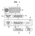
- FIG. 1 Conceptual construction of a medicine ejection apparatus of the present invention which ejects a medicine for medicating a user is illustrated in FIG. 1 .
- An element which generates energy for ejecting a medicine is arranged in the ejection head 107 which is a medicine ejecting unit, and when the element is driven by a head drive circuit 104, the medicine is ejected from an ejection opening.
- a medicine tank 108 which contains the medicine which is ejected is connected to the ejection head 107, and the ejection head 107 and medicine tank 108 are integrated to construct the medicine cartridge 101.
- Such an integrated type cartridge can be attached to a medicine ejection apparatus detachably.
- a CPU103 which is a control unit that controls the whole apparatus includes at least memory 103a, a driving condition determining unit 103b, and a drive control unit 103c.
- Many settings of the whole apparatus are stored in the memory 103a, and in particular, a user's dose and the like are stored. Hereinafter, this may be called “set ejection amount.”
- the drive control unit 103c sends a command to the head drive circuit 104 to perform a drive start and a drive stop of an ejection energy generating element, that is, drive control of the ejection head 107.
- the drive start and drive stop of the element that is, the control of an ejection start and an ejection stop of a medicine is performed on the basis of an output signal from a sensor 102 which detects a user's inhalation.
- a sensor 102 which detects a user's inhalation.
- it can be mentioned to start ejection by a user's button operation or the like, and to stop it after performing the ejection for a predetermined time.
- This specified time can be set at a suitable value beforehand from a user's inhalation time and the like.
- the inhalation detecting sensor 102 When a user's inhalation is detected by the inhalation detecting sensor 102, an output signal is sent to the CPU 103, drive of the ejection head 107 is started by the drive control unit 103c, and the medicine is ejected.
- the drive of the ejection head 107 is stopped by the drive control unit 103c, and the ejection of the medicine is ended.
- a total amount of the medicine which is ejected in the period is determined by an ejection amount recognizing unit 105 as an ejection amount determining unit.
- the total amount of the ejected medicine reaches set ejection amount by the total amount of the medicine determined by the ejection amount recognizing unit 105 being compared with the set ejection amount recorded in memory 103a.
- it is enabled again to drive the ejection head 107 by the drive control unit 103c so as to eject an amount of medicine calculated based on difference from the set ejection amount.
- the calculated amount is amount itself corresponding to the difference between the set ejection amount and the total amount of the medicine which is ejected, the present invention is not limited to this.
- An essence of the present invention is to perform second ejection on the basis of difference between ejection amount in one-time ejection, and ejection amount set beforehand. Even when a dose (set ejection amount) cannot be inhaled by one time of inhalation, an amount of ejection which is the same as or almost the same as the set ejection amount can be performed.
- the driving condition determining unit 103b as a determining unit determines driving conditions of the ejection head 107 for ejecting the amount of medicine calculated based on the difference from the set ejection amount. Then, according to the determined driving conditions, it can be performed to eject the same amount as the set ejection amount by enabling drive of the ejection head 107 by the drive control unit 103c.
- the ejection amount recognizing unit 105 cannot grasp ejection amount of a medicine in-situ in the midst of ejection, by determining ejection conditions for achieving predetermined ejection amount in advance and performing drive according to the conditions, it can be determined that the ejection of the predetermined amount is completed.
- the ejection amount recognizing unit 105 is arranged in the CPU 103 depending on an embodiment.
- second and later ejections may be performed automatically or may be performed by a user's switch depression. When performed automatically, it can be performed on the basis of an output signal of the inhalation detecting sensor 102.
- a main body of the medicine ejection apparatus can have a display unit 106, such as an LCD display, and it can be performed to display determination result of whether it reaches the set ejection amount, and the like in this display unit 106.
- a display unit 106 such as an LCD display
- the medicine ejecting unit (ejection head) 107 has two or more ejection openings, and arbitrary ejection energy generating elements provided in relation of one-to-one, one-to-many and many-to-one to an ejection opening.
- An electrothermal transducer which gives heat energy to a medicine, or an electromechanical transducer which gives mechanical energy can be exemplified.
- a method (thermal jet system) of giving heat energy to a medicine and making it ejected using an electrothermal transducer and a method (piezo jet system) of ejecting a medicine using oscillating pressure of an electromechanical transducer (for example, a piezoelectric element) which gives mechanical energy to the medicine can be exemplified.
- electromechanical transducer for example, a piezoelectric element
- the ejection method is selectable according to a type of a medicine, or the like.
- a thermal jet system When a thermal jet system is used, it can be performed to enhance size accuracy and repeatability of an aperture of an ejection opening, heat amount of a thermal pulse used for ejection, and a micro heater as an electrothermal transducer, in regard to each ejection head. Thus, it can be performed to achieve a narrow droplet diameter distribution. In addition, head manufacturing cost is low and applicability to small apparatuses which need frequent exchange of a head is also high. Hence, when the medicine ejection apparatus is requested to have portability or convenience, in particular, an ejection principle of a thermal jet type can be adopted.
- ejection amount is changeable by changing an ejecting operation period when the medicine is ejected.
- the "ejecting operation period" or “ejection period” means time from giving a first pulse to the ejection energy generating element to finishing giving a last pulse with continuously giving a series of pulses, that is, a series of period while a pulse train for ejection energy generation is supplied. It can be performed to increase medicine ejection amount by making the ejecting operation period longer.
- the "ejection frequency” is equivalent to the number of pulse signals for ejecting the medicine given to the ejection energy generating element per unit time. This may be called a drive frequency.
- the ejection amount of the medicine for achieving a necessary dosage may be changed by combining these both methods.
- a pressure sensor arranged in an air current path can be exemplified. It can be performed to grasp inhalation conditions, such as a user's inhalation start and subsequent inhalation strength, by the pressure sensor detecting a pressure change (negative pressure fluctuation) generated in the air current path by a user's inhalation. Besides that, a common flow rate sensor which measures a gas flow rate in the air flow path can be used.
- Concept of the medicine used for the present invention includes not only a medicine such as a pharmaceutical compound which shows a pharmacological and physiological effect, but also a component for a seductive taste or a seductive smell, a dye, a pigment, and the like in addition to the pharmaceutical compound. Then, it does not matter whether a medicine is liquid or powder.
- the medical fluid used for the present invention means a liquid medicine or a liquid medium including a medicine.
- Arbitrary additive agents may be included in the medical fluid. Any of dissolution, dispersion, emulsification, suspension, and slurry may be sufficient as a state of the medicine in liquid, and when equalized in liquid, it is better.
- the main medium of the liquid is plain water or an organic solvent, and in consideration of being administered into a living body, it is suitable that plain water is the main medium.
- One time of ejecting operation period of the medicine ejection apparatus which is a suitable embodiment of the present invention and has the inhalation detecting sensor 102 depends on a user's inhalation condition. In such a case, in particular, total amount of the medicine which is ejected in one time of ejecting operation period may not reach ejection amount set beforehand as one dose.
- a control method of the medicine ejection apparatus of the present invention which can eject set ejection amount securely also in such a case although inhalation is divided into multiple times will be specifically described below.
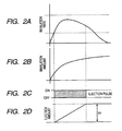
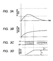
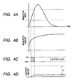
- FIGS. 2A to 4D Patterns considered as relation between the medicine ejection period and the user's inhalation are illustrated in FIGS. 2A to 4D .
- FIGS. 2A , 3A , and 4A illustrate changes of user's inhalation rate (inhalation strength) which is measurable directly by an inhalation detecting sensor. These are also called “inhalation profiles.”
- FIGS. 2B , 3B and 4B are the time series changes of the inhalation amount from an inhalation start, and become time integration values of inhalation profiles which are illustrated in FIGS. 2A , 3A , and 4A , respectively.
- FIGS. 2C , 3C , and 4C illustrate periods when a pulse is given to an ejection energy generating element. A period illustrated by shading is an ejection period.
- FIGS. 2D , 3D , and 4D illustrate the ejection total amount of the medicine in each time. A horizontal axis is the time in each case.
- FIGS. 2A to 2D illustrate the cases that a user performs suitable inhalation.
- Ejection of a medicine is performed only within the range of the user's inhalation flow rate being in the predetermined inhalation flow rate illustrated by doted lines in FIG. 2A .
- Ejection is started by the drive control unit 103c when a user starts inhalation and predetermined inhalation flow rate is detected.
- Ejection is ended when it reaches set ejection amount V t without stopping ejection while inhalation flow rate is kept within a suitable range. In this case, the set ejection amount can be ejected in one time of inhalation.
- FIGS. 3A to 3D are graphs of cases that a user's inhalation is weak and the set ejection amount cannot be ejected in one time of inhalation. Since an inhalation rate becomes out of a lower limit of the predetermined range before the set amount is ejected, ejection is stopped.
- Driving conditions of the element for it are determined by the driving condition determining unit 103b.
- FIGS. 4A to 4D are graphs when a user's inhalation rate is too strong and it exceeds an upper limit of a proper inhalation rate.
- an inhalation rate enters into proper limits and ejection is once started, the ejection is stopped because of the upper limit being exceeded.
- it becomes within proper limits once again in a second half of the inhalation operation it can be performed not to eject the medicine in the meantime. This is because it is clear that lung deposition efficiency falls in the second half of inhalation since a user's one-time inhalation amount is already close to saturation.
- FIGS. 4A to 4D are graphs when a user's inhalation rate is too strong and it exceeds an upper limit of a proper inhalation rate.
- difference between the total amount of the medicine which is ejected and the set ejection amount is calculated and a user is prompted to perform next inhalation. Then, similarly, in accordance with the inhalation, ejection is performed until it reaches the set ejection amount.
- a suitable inhalation rate range is approximately 0.1 to 1.0 L/s and so for an adult, it may change with individual difference, illness, conditions, and the like.
- inhalation amount As respiratory parameters used for the inhalation conditions which determines the ejection period, besides the above-mentioned inhalation rate, inhalation amount may be used.
- the “inhalation rate” means speed of an air current generated in an air current path, and it is calculated on the basis of speed of air which passes a given point in an inhalation detection unit.
- the “inhalation amount” is amount of inhaled air which is calculated by time integration of inhalation rate data.
- Suitable inhalation conditions differ according to a medicine to be used. According to a site of a respiratory organ in which a medicine is made to act, a suitable droplet diameter, a particle size distribution, and inhalation conditions which are suitable for them are set.
- a medicine to be inhaled is a bronchodilator, it is better not to arrive at a palmonary alveolus since a site to be made to act is a bronchus.
- optimum conditions also depend on a user's physical and physiological features, it turns out that generally it is better to make liquid droplets have some particle size distribution, and not to increase inhalation flow rate and inhalation amount.
- Setting of an inhalation condition is set so that an ejection flag (FLG) may become ON when an inhalation rate is within a certain range. Furthermore, it is also good to find inhalation amount from time integration of an inhalation rate and to add a rate with a user's maximum inspiratory capacity (IC), which was measured beforehand, to the condition. By adding the inhalation amount on the condition, it can be performed to deliver a spraying medicine to lungs before the lungs are filled with air to be inhaled.
- FLG ejection flag
- IC maximum inspiratory capacity
- inhalation condition data may be recorded on a recording medium inside a main body, or a user may store it as external memory.
- FIG. 5 An example of a control method of the medicine ejection apparatus of the present invention is illustrated in a flowchart in FIG. 5 .
- the medicine ejection apparatus performs initial setting (S001). Specifically, it is confirmed whether the set ejection amount V T is set as one dose in the memory 103a, and count of the ejection total amount V t at the time t from an ejection start is reset to zero. In addition, error detection is reset.
- the CPU103 monitors an output signal from the inhalation detecting sensor 102, and confirms whether inhalation conditions fall in the predetermined ranges (S002).
- the ejection amount V t can be determined in-situ by the ejection amount recognizing unit 105. In this case, whether the set ejection amount V T is reached can be determined directly. Next, since the ejection conditions for ejecting the set ejection amount V T are determined, it may be determined by whether or not ejection on the ejection conditions has been completed.
- the ejection conditions at the time of ejecting the V r are calculated according to necessity by the driving condition determining unit 103b (S010).
- a counter of the ejection amount V t is reset to zero, and the set ejection amount V T in the second ejection is made into the residual ejection amount V r .
- Error detection is reset (S011). The above-mentioned flow is repeated hereafter until the set ejection amount is ejected completely.
- ejection amount used for the present invention it can be calculated from the number of given pulses (hereafter, this is called an ejection shot number) and a droplet diameter when an ejection principle of an ink jet is used for a medicine ejecting unit. Since being dependent on a diameter of an ejection opening (nozzle), a droplet diameter can be grasped as a constant beforehand and an ejection shot number can be calculated from ejection conditions. In this calculation method, even if ejection is performed with an ejection condition being changed during one time of inhalation, its ejection amount can be grasped accurately.
- volume of the medicine tank 108 changes according to amount of an inside medicine
- the amount which is ejected can be also grasped by detecting the volume change.
- a method of detecting a displacement of a movable wall, which constructs a part of the medicine tank 108, by a distance sensor such as an optical type, or an ultrasonic type can be mentioned.
- a liquid amount supplied to the ejection head 107 can be measured by installing a liquid flow rate sensor between the ejection head 107 and the medicine tank 108, ejection amount can be also grasped from this value.
- ejection amount can be also grasped by measuring a pressure change occurring in the medicine tank corresponding to ejection amount.
- a pressure sensor which measures internal pressure of the medicine tank can be used.
- ejection amount recognizing units may be used independently, or may be used in combination.
- FIG. 6 is a perspective view illustrating appearance of an inhaler 100 which is an example of the medicine ejection apparatus of the present invention and makes a user inhale a medicine.
- a main body armour is formed by a housing case 17 and an access cover 18.
- Reference numeral 40 denotes a lock release button of the access cover. Construction that a hook portion 19 ( FIG. 7 ) provided so that the access cover 18 may not open in use is caught by a hook holding shaft which operates integrally with a lock release button 40 energized by a spring is adopted.
- the display unit 106 for displaying a dose, time, an error, and the like is provided in the access cover 18.
- a menu switching button 11 for a user to perform setting, an up button 12 and a down button 13 which are setting buttons, and a determination button 14 are provided.
- FIG. 7 illustrates a state that the access cover 18 is open in the inhaler in FIG. 6 .
- the ejection head unit 107 which is a medicine ejecting unit that is detachable to the apparatus body, and the medicine tank 108, which is a medicine containing unit, can be seen.
- the ejection head unit 107 ejects the medicine toward an air current path 7.
- the air current path 7 is illustrated in FIG. 6 , its part is hidden by a cover 31 in FIG. 7 .
- the inlet 20 and air current path 7 are integrated.
- the inlet 20 is thrown away every inhalation, or it is washed after inhalation and is re-used.
- the ejection head unit 107 and the medicine tank 108 will be exchanged when amount of a medicine in the medicine tank 108 becomes less than set ejection amount.
- a function of counting ejection amount is prepared in a main body and residual amount is computable by this ejection amount count function, it is feasible to perform notification of exchange time to prompt a user to exchange, or not to perform ejection until exchange is completed.
- Reference numeral 31 denotes a drive unit protective cover for a user not to touch an internal mechanism of an inhaler easily.
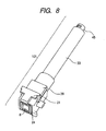
- FIG. 8 A perspective view of the cartridge 101 into which the ejection head unit 107 and medicine tank 108 are integrated is illustrated in FIG. 8 .
- the head protective cap 21 which has a medical fluid absorber so as to contact to an ejection opening surface of the ejection head 8 for the purpose of preventing an ejection opening from being deformed or preventing it from being stained is arranged.
- the head protective cap 21 releases the ejection head 8 so as to be able to eject the medicine from the ejection opening to the air current path 7 at the time of medicine ejection.
- a release state is illustrated in FIG. 8 .
- the ejection head unit 107 is mainly constructed of a housing 39, and the ejection head 8 is a thermal ink jet type ejection head publicly known in a p printer field.
- the ejection head 8 is a thermal ink jet type ejection head publicly known in a p printer field.
- An electrical connection member (contact pin) for supplying electric power for making a heater provided in the ejection head 8 generate heat energy from a power source provided in the main body is arranged on a not-illustrated surface of the housing 39.
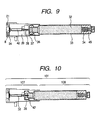
- FIG. 9 is a principal sectional view in a state that the cap 21 protects the ejection head 8 in FIG. 8 .
- a medical fluid pass 42 is provided so as to be connected to this, and a medical fluid is supplied to the ejection head 8.
- the medicine tank 108 is mainly constructed of a glass container 33 for accommodating a medicine.
- a fixed rubber stopper 36 is held down by the glass container 33 with a caulking metal fitting 37 which is made of aluminum.
- a movable rubber stopper 34 is provided, and the movable rubber stopper 34 will move by amount of a medicine 32 decreasing by ejection from in the glass container 33. Sealing property of the medicament container 33 is maintained by this construction, and denaturation and a concentration change of the medicine 32 are suppressed to the minimum.
- a connection joint 45 with a main body side plunger for moving this positively is provided.
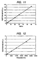
- FIG. 10 is a sectional view in a state that the medicine tank 108 is pushed into the ejection head unit 107 in FIG. 9 , and both are made to communicate. It illustrates the state that the hollow needle 38 breaks through the fixed rubber stopper 36, a medicine pass 42 is formed, and the medicine in the medicine tank 108 flows into the ejection head 8. Ejection is enabled by the medicine being filled in a heater, a top face portion and an ejection nozzle of the ejection head unit. Filling of the medicine 32 ( FIG. 11 ) to the ejection head 8 is performed by pushing the movable rubber stopper 34.
- Formula 1 is an operational expression of ejection amount on the basis of digital ejection by an ink jet system.
- V t V 1 ⁇ n ⁇ f ⁇ t ⁇ A
- the correction value A is a coefficient which corrects volume by liquid droplets called satellites except main liquid droplets ejected from one nozzle when one drive pulse is applied.
- a particle diameter of a main liquid droplet is constant.
- it can be performed to measure amount ejected in t seconds accurately by recording values of V 1 and A beforehand since ejection of the satellites also is constant depending on ejection conditions. It is considered that the ejection of the satellites is affected by, for example, pulse width and a drive voltage. "Pulse width" here is application time in one pulse signal application.
- a "drive voltage” is a voltage given to an ejection energy generating element. Since the nozzle number n is a number of holes ejecting a medicine, a number used for ejection is applied to Formula 1. The nozzle number to be used is changeable by ejection conditions.
- ejection total amount in a predetermined ejection period can be calculated from the ejection conditions. If residual ejection amount V r is calculated, the ejection conditions of second time of ejection are determined, but when not changing the conditions, such as an ejection frequency, the driving condition determining unit 103b determines so as to shorten the ejection period than that in the first time of ejection. In this way, when this embodiment is adopted, it is necessary to determine the ejection conditions in the second time of ejection.
- a range of a suitable inhalation rate is 0.1 to 1.0 L/s and detection is performed with a pressure sensor in an air current path portion in a sectional area of 10 mm 2 , the above-mentioned suitable range is detectable as -0.12 to -6 kPa.
- FIGS. 13 and 14 show that before connection and FIG. 14 shows that after the connection.
- the medical fluid pass 42 is provided so as to be connected to this, and a medical fluid is supplied to the ejection head 8.
- the medical fluid pass 42 branches in a direction of a pressure detection opening 23 on the way.
- a pressure sensor provided in an inhalation apparatus body side is connected to the pressure detection opening 23.
- a sealant (O-ring) 22 for preventing a pressure leak at the time of the pressure sensor connection after main body attachment is arranged.
- Pressure in a tank is transmitted from a branched small hole to the pressure detection opening 23 through a space in an upper portion.
- the upper portion (a surface dividing the pressure detection opening 23 and this space) of this space becomes a membrane which is constructed from a flexible material, and detects a tank internal pressure from a displacement of the membrane by a pressure change by the pressure sensor in the main body side.
- the other main construction of the medicine cartridge 101 is the same as that of the first example.
- Experimental result of investigating relation between the pressure and the ejection amount in the medicine tank 108 is illustrated in a graph in FIG. 15 .
- Ejection was performed on tank internal volume of 2 mL, a droplet diameter of 3 ⁇ m, ejection frequency 10 kHz, and one-second ejection, and ejection amount of 2 ⁇ L/time.
- the movable rubber stopper 34 is fixed so as not to move.
- an interior of the medicine tank 108 is an airtight container, and it is isolated from the open air besides an ejection opening of the ejection head 8. Therefore, when the medical fluid is ejected from the ejection opening 8, corresponding to the ejection amount, negative pressure occurs in the container.
- the ejection amount can be determined to the extent of 40 ⁇ l by this method.
- the ejection amount can be determined.
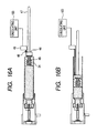
- FIGS. 16A and 16B Sectional views of the medicine cartridge 101 according to the third embodiment of the present invention are illustrated in FIGS. 16A and 16B.
- FIG. 16A is a sectional view in a state of an early stage of ejection
- 16B is one in a state that ejection advances and the medical fluid in the medicine tank decreases.
- the movable rubber stopper 34 is moved by a piston with keeping the negative pressure in the medicine tank constant during ejection.
- the ejection amount can be determined by measuring the movement of the rubber stopper.
- a position sensor 49 is oppositely provided to the movable rubber stopper 34, and a detection plate 48 is provided in a part of the magnets 46.
- the ejection amount can be measured accurately by reading the movement amount of the movable rubber stopper 34 using the position sensor 49.
- the ejection amount can be determined.
- the medicine ejection apparatus of the present invention may be used for various uses besides for medicine inhalation.
- it can be also used for a spray form ejecting apparatus of aromatics, an inhalation apparatus of luxury goods, such as nicotine, and the like.
- the medicine ejection apparatus of the present invention is applicable to various uses which need certain and sanitary ejection.
Landscapes
- Health & Medical Sciences (AREA)
- Engineering & Computer Science (AREA)
- General Health & Medical Sciences (AREA)
- Biomedical Technology (AREA)
- Heart & Thoracic Surgery (AREA)
- Hematology (AREA)
- Life Sciences & Earth Sciences (AREA)
- Animal Behavior & Ethology (AREA)
- Anesthesiology (AREA)
- Public Health (AREA)
- Veterinary Medicine (AREA)
- Bioinformatics & Cheminformatics (AREA)
- Pulmonology (AREA)
- Medicinal Preparation (AREA)
- Medical Preparation Storing Or Oral Administration Devices (AREA)
- Containers And Packaging Bodies Having A Special Means To Remove Contents (AREA)
- Coating Apparatus (AREA)
- Ink Jet (AREA)
- Application Of Or Painting With Fluid Materials (AREA)
Applications Claiming Priority (3)
| Application Number | Priority Date | Filing Date | Title |
|---|---|---|---|
| JP2008014458 | 2008-01-25 | ||
| JP2008103554A JP2009195669A (ja) | 2008-01-25 | 2008-04-11 | 薬剤吐出装置及びその制御方法 |
| PCT/JP2009/051515 WO2009093759A1 (en) | 2008-01-25 | 2009-01-23 | Medicine ejection apparatus and control method thereof |
Publications (2)
| Publication Number | Publication Date |
|---|---|
| EP2237823A1 EP2237823A1 (en) | 2010-10-13 |
| EP2237823B1 true EP2237823B1 (en) | 2012-12-12 |
Family
ID=40473319
Family Applications (1)
| Application Number | Title | Priority Date | Filing Date |
|---|---|---|---|
| EP09703630A Revoked EP2237823B1 (en) | 2008-01-25 | 2009-01-23 | Medicine ejection apparatus and control method thereof |
Country Status (6)
Families Citing this family (28)
| Publication number | Priority date | Publication date | Assignee | Title |
|---|---|---|---|---|
| JP4689340B2 (ja) * | 2005-05-02 | 2011-05-25 | キヤノン株式会社 | 吐出用液体医薬組成物 |
| JP5207885B2 (ja) * | 2008-09-03 | 2013-06-12 | キヤノン株式会社 | 画素回路、発光表示装置及びそれらの駆動方法 |
| RS55481B1 (sr) * | 2009-07-17 | 2017-04-28 | Nektar Therapeutics | Sistemi i postupci za upravljanje zaptivenim raspršivačem |
| US8308679B2 (en) | 2009-12-30 | 2012-11-13 | Medtronic Minimed, Inc. | Alignment systems and methods |
| US8932256B2 (en) | 2009-09-02 | 2015-01-13 | Medtronic Minimed, Inc. | Insertion device systems and methods |
| US8900190B2 (en) | 2009-09-02 | 2014-12-02 | Medtronic Minimed, Inc. | Insertion device systems and methods |
| US8998858B2 (en) | 2009-12-29 | 2015-04-07 | Medtronic Minimed, Inc. | Alignment and connection systems and methods |
| US8998840B2 (en) | 2009-12-30 | 2015-04-07 | Medtronic Minimed, Inc. | Connection and alignment systems and methods |
| US9039653B2 (en) | 2009-12-29 | 2015-05-26 | Medtronic Minimed, Inc. | Retention systems and methods |
| US8435209B2 (en) | 2009-12-30 | 2013-05-07 | Medtronic Minimed, Inc. | Connection and alignment detection systems and methods |
| US9421321B2 (en) | 2009-12-30 | 2016-08-23 | Medtronic Minimed, Inc. | Connection and alignment systems and methods |
| US11497850B2 (en) | 2009-12-30 | 2022-11-15 | Medtronic Minimed, Inc. | Connection and alignment detection systems and methods |
| US20120215163A1 (en) | 2009-12-30 | 2012-08-23 | Medtronic Minimed, Inc. | Sensing systems and methods |
| US9719184B2 (en) | 2010-12-28 | 2017-08-01 | Stamford Devices Ltd. | Photodefined aperture plate and method for producing the same |
| US9346075B2 (en) | 2011-08-26 | 2016-05-24 | Nordson Corporation | Modular jetting devices |
| BR112014027624B1 (pt) | 2012-06-11 | 2021-01-19 | Stamford Devices Ltd | método de fabricar uma lâmina de placa de orifícios de formação de aerossol, placa de orifícios, dispositivo de formação de aerossol e lâmina de placa de orifícios |
| EP2872917B1 (en) | 2012-07-11 | 2016-08-31 | Sanofi-Aventis Deutschland GmbH | Arrangement and method for determining a stopper position |
| US9907902B2 (en) | 2013-12-20 | 2018-03-06 | Maxim Integrated Products, Inc. | Precise accurate measurement of the administration of drugs using the injection method by means of ultrasonic pulse-echo principles |
| WO2015177311A1 (en) | 2014-05-23 | 2015-11-26 | Stamford Devices Limited | A method for producing an aperture plate |
| CN105031768B (zh) * | 2015-07-09 | 2019-05-21 | 刘英志 | 一种能够精确控制剂量的麻醉针 |
| CN105396206A (zh) * | 2015-11-27 | 2016-03-16 | 江苏鹿得医疗电子股份有限公司 | 带吸气感应间歇送风式医用超声波雾化器 |
| CN105999485B (zh) * | 2016-06-21 | 2019-12-31 | 青岛未来移动医疗科技有限公司 | 一种智能雾化器系统及其监控使用方法 |
| CN106178203A (zh) * | 2016-08-30 | 2016-12-07 | 苏州品诺维新医疗科技有限公司 | 一种药液雾化设备及其操作方法 |
| US10609957B2 (en) * | 2016-11-22 | 2020-04-07 | Funai Electric Co., Ltd. | Vapor delivery device |
| FR3077495B1 (fr) * | 2018-02-07 | 2023-04-14 | Aptar France Sas | Ensemble de distribution de produit fluide. |
| JP7180153B2 (ja) * | 2018-07-11 | 2022-11-30 | 大日本印刷株式会社 | 吸入判定装置及び吸入判定システム |
| CN110975075A (zh) * | 2019-11-25 | 2020-04-10 | 王舒扬 | 一种双控式压力定量气雾吸入器 |
| US20230310762A1 (en) * | 2022-03-29 | 2023-10-05 | Funai Electric Co., Ltd. | Method of jetting a fluid that is synchronized with breathing |
Family Cites Families (21)
| Publication number | Priority date | Publication date | Assignee | Title |
|---|---|---|---|---|
| US5363842A (en) * | 1991-12-20 | 1994-11-15 | Circadian, Inc. | Intelligent inhaler providing feedback to both patient and medical professional |
| DK0706352T3 (da) | 1993-06-29 | 2002-07-15 | Ponwell Entpr Ltd | Dispenser |
| CN100566769C (zh) * | 1993-06-29 | 2009-12-09 | 茵捷特数码浮质有限公司 | 利用吸入方式服用物质的方法和器具 |
| CH686872A5 (de) * | 1993-08-09 | 1996-07-31 | Disetronic Ag | Medizinisches Inhalationsgeraet. |
| US5435282A (en) * | 1994-05-19 | 1995-07-25 | Habley Medical Technology Corporation | Nebulizer |
| US5509404A (en) | 1994-07-11 | 1996-04-23 | Aradigm Corporation | Intrapulmonary drug delivery within therapeutically relevant inspiratory flow/volume values |
| CN2427204Y (zh) * | 2000-04-12 | 2001-04-25 | 姜家玉 | 移动式自动灌注与输液装置 |
| US6623785B2 (en) * | 2001-06-07 | 2003-09-23 | Hewlett-Packard Development Company, L.P. | Pharmaceutical dispensing apparatus and method |
| JP2003024442A (ja) * | 2001-07-13 | 2003-01-28 | Olympus Optical Co Ltd | 医用噴霧装置 |
| GB2396825B (en) * | 2002-11-20 | 2004-12-08 | Profile Respiratory Systems Lt | Improved inhalation method and apparatus |
| JP2004249208A (ja) * | 2003-02-20 | 2004-09-09 | Omron Healthcare Co Ltd | 吸入器及び吸入システム |
| US7726303B2 (en) | 2003-02-25 | 2010-06-01 | Hewlett-Packard Development Company, L.P. | Controlled medicament ejection |
| JP4136741B2 (ja) | 2003-03-19 | 2008-08-20 | キヤノン株式会社 | 薬剤吐出装置 |
| CN2684161Y (zh) * | 2003-09-17 | 2005-03-09 | 张睐 | 医用氧气流量计量器 |
| US7513253B2 (en) * | 2004-08-02 | 2009-04-07 | Canon Kabushiki Kaisha | Liquid medication cartridge and inhaler using the cartridge |
| JP2006198127A (ja) * | 2005-01-20 | 2006-08-03 | Canon Inc | 吸入装置 |
| EP1704885A1 (de) * | 2005-03-24 | 2006-09-27 | Disetronic Licensing AG | Vorrichtung für die dosierte Verabreichung eines fluiden Produkts |
| JP4789555B2 (ja) * | 2005-09-13 | 2011-10-12 | キヤノン株式会社 | 液剤吐出装置 |
| AU2007238316A1 (en) * | 2006-04-05 | 2007-10-25 | Microdose Therapeutx, Inc. | Variable dose inhalation device |
| CN2905088Y (zh) * | 2006-04-10 | 2007-05-30 | 陈清甫 | 便携式雾化给药装置 |
| JP4895388B2 (ja) * | 2006-07-25 | 2012-03-14 | キヤノン株式会社 | 薬剤吐出装置 |
-
2008
- 2008-04-11 JP JP2008103554A patent/JP2009195669A/ja active Pending
-
2009
- 2009-01-23 AU AU2009206947A patent/AU2009206947A1/en not_active Abandoned
- 2009-01-23 EP EP09703630A patent/EP2237823B1/en not_active Revoked
- 2009-01-23 CN CN2009801025963A patent/CN101918058A/zh active Pending
- 2009-01-23 WO PCT/JP2009/051515 patent/WO2009093759A1/en active Application Filing
- 2009-01-23 CN CN201410602146.3A patent/CN104288878A/zh active Pending
- 2009-01-23 US US12/532,867 patent/US8333188B2/en not_active Expired - Fee Related
Also Published As
| Publication number | Publication date |
|---|---|
| AU2009206947A1 (en) | 2009-07-30 |
| US8333188B2 (en) | 2012-12-18 |
| US20100275916A1 (en) | 2010-11-04 |
| JP2009195669A (ja) | 2009-09-03 |
| WO2009093759A1 (en) | 2009-07-30 |
| CN104288878A (zh) | 2015-01-21 |
| CN101918058A (zh) | 2010-12-15 |
| EP2237823A1 (en) | 2010-10-13 |
Similar Documents
| Publication | Publication Date | Title |
|---|---|---|
| EP2237823B1 (en) | Medicine ejection apparatus and control method thereof | |
| JP4895388B2 (ja) | 薬剤吐出装置 | |
| JP5383097B2 (ja) | 薬剤吐出装置及びその制御方法 | |
| JP6543240B2 (ja) | 吸入器 | |
| JP5207679B2 (ja) | 薬剤吐出装置 | |
| JP5159482B2 (ja) | 吸入装置 | |
| EP2641630B1 (en) | Self-sensing respiratory treatment device | |
| JP4393518B2 (ja) | 薬液カートリッジおよび該カートリッジを用いた吸入装置 | |
| TWI253428B (en) | Medicament dispenser | |
| JP5558685B2 (ja) | 吸入装置 | |
| JP4789555B2 (ja) | 液剤吐出装置 | |
| JP4914067B2 (ja) | 空気流調節を有する吸入器 | |
| JP5602360B2 (ja) | 薬剤吐出装置及び該装置の吐出性能の把握方法 | |
| EP1970087B1 (en) | Inhaler and ejection head unit attachable to the inhaler | |
| WO2005075012A1 (en) | Systems and methods for particle detection | |
| JP5165025B2 (ja) | 空気流調節を有する吸入器 | |
| JP2004350985A (ja) | 肺吸引用液滴吐出装置 | |
| JP2004350976A (ja) | 肺吸引用液滴吐出装置 |
Legal Events
| Date | Code | Title | Description |
|---|---|---|---|
| PUAI | Public reference made under article 153(3) epc to a published international application that has entered the european phase |
Free format text: ORIGINAL CODE: 0009012 |
|
| 17P | Request for examination filed |
Effective date: 20100825 |
|
| AK | Designated contracting states |
Kind code of ref document: A1 Designated state(s): AT BE BG CH CY CZ DE DK EE ES FI FR GB GR HR HU IE IS IT LI LT LU LV MC MK MT NL NO PL PT RO SE SI SK TR |
|
| AX | Request for extension of the european patent |
Extension state: AL BA RS |
|
| DAX | Request for extension of the european patent (deleted) | ||
| REG | Reference to a national code |
Ref country code: DE Ref legal event code: R079 Ref document number: 602009011888 Country of ref document: DE Free format text: PREVIOUS MAIN CLASS: A61M0011000000 Ipc: A61M0015020000 |
|
| GRAP | Despatch of communication of intention to grant a patent |
Free format text: ORIGINAL CODE: EPIDOSNIGR1 |
|
| RIC1 | Information provided on ipc code assigned before grant |
Ipc: A61M 11/00 20060101ALI20120523BHEP Ipc: B65D 83/44 20060101ALI20120523BHEP Ipc: A61M 15/02 20060101AFI20120523BHEP Ipc: A61M 16/00 20060101ALI20120523BHEP |
|
| GRAS | Grant fee paid |
Free format text: ORIGINAL CODE: EPIDOSNIGR3 |
|
| GRAA | (expected) grant |
Free format text: ORIGINAL CODE: 0009210 |
|
| AK | Designated contracting states |
Kind code of ref document: B1 Designated state(s): AT BE BG CH CY CZ DE DK EE ES FI FR GB GR HR HU IE IS IT LI LT LU LV MC MK MT NL NO PL PT RO SE SI SK TR |
|
| REG | Reference to a national code |
Ref country code: GB Ref legal event code: FG4D |
|
| REG | Reference to a national code |
Ref country code: CH Ref legal event code: EP |
|
| REG | Reference to a national code |
Ref country code: AT Ref legal event code: REF Ref document number: 588040 Country of ref document: AT Kind code of ref document: T Effective date: 20121215 |
|
| REG | Reference to a national code |
Ref country code: IE Ref legal event code: FG4D |
|
| REG | Reference to a national code |
Ref country code: DE Ref legal event code: R096 Ref document number: 602009011888 Country of ref document: DE Effective date: 20130207 |
|
| PG25 | Lapsed in a contracting state [announced via postgrant information from national office to epo] |
Ref country code: NO Free format text: LAPSE BECAUSE OF FAILURE TO SUBMIT A TRANSLATION OF THE DESCRIPTION OR TO PAY THE FEE WITHIN THE PRESCRIBED TIME-LIMIT Effective date: 20130312 Ref country code: SE Free format text: LAPSE BECAUSE OF FAILURE TO SUBMIT A TRANSLATION OF THE DESCRIPTION OR TO PAY THE FEE WITHIN THE PRESCRIBED TIME-LIMIT Effective date: 20121212 Ref country code: LT Free format text: LAPSE BECAUSE OF FAILURE TO SUBMIT A TRANSLATION OF THE DESCRIPTION OR TO PAY THE FEE WITHIN THE PRESCRIBED TIME-LIMIT Effective date: 20121212 Ref country code: ES Free format text: LAPSE BECAUSE OF FAILURE TO SUBMIT A TRANSLATION OF THE DESCRIPTION OR TO PAY THE FEE WITHIN THE PRESCRIBED TIME-LIMIT Effective date: 20130323 Ref country code: FI Free format text: LAPSE BECAUSE OF FAILURE TO SUBMIT A TRANSLATION OF THE DESCRIPTION OR TO PAY THE FEE WITHIN THE PRESCRIBED TIME-LIMIT Effective date: 20121212 |
|
| REG | Reference to a national code |
Ref country code: NL Ref legal event code: VDEP Effective date: 20121212 |
|
| REG | Reference to a national code |
Ref country code: AT Ref legal event code: MK05 Ref document number: 588040 Country of ref document: AT Kind code of ref document: T Effective date: 20121212 |
|
| REG | Reference to a national code |
Ref country code: LT Ref legal event code: MG4D |
|
| PG25 | Lapsed in a contracting state [announced via postgrant information from national office to epo] |
Ref country code: SI Free format text: LAPSE BECAUSE OF FAILURE TO SUBMIT A TRANSLATION OF THE DESCRIPTION OR TO PAY THE FEE WITHIN THE PRESCRIBED TIME-LIMIT Effective date: 20121212 Ref country code: LV Free format text: LAPSE BECAUSE OF FAILURE TO SUBMIT A TRANSLATION OF THE DESCRIPTION OR TO PAY THE FEE WITHIN THE PRESCRIBED TIME-LIMIT Effective date: 20121212 Ref country code: GR Free format text: LAPSE BECAUSE OF FAILURE TO SUBMIT A TRANSLATION OF THE DESCRIPTION OR TO PAY THE FEE WITHIN THE PRESCRIBED TIME-LIMIT Effective date: 20130313 |
|
| PG25 | Lapsed in a contracting state [announced via postgrant information from national office to epo] |
Ref country code: AT Free format text: LAPSE BECAUSE OF FAILURE TO SUBMIT A TRANSLATION OF THE DESCRIPTION OR TO PAY THE FEE WITHIN THE PRESCRIBED TIME-LIMIT Effective date: 20121212 Ref country code: IS Free format text: LAPSE BECAUSE OF FAILURE TO SUBMIT A TRANSLATION OF THE DESCRIPTION OR TO PAY THE FEE WITHIN THE PRESCRIBED TIME-LIMIT Effective date: 20130412 Ref country code: BE Free format text: LAPSE BECAUSE OF FAILURE TO SUBMIT A TRANSLATION OF THE DESCRIPTION OR TO PAY THE FEE WITHIN THE PRESCRIBED TIME-LIMIT Effective date: 20121212 Ref country code: CZ Free format text: LAPSE BECAUSE OF FAILURE TO SUBMIT A TRANSLATION OF THE DESCRIPTION OR TO PAY THE FEE WITHIN THE PRESCRIBED TIME-LIMIT Effective date: 20121212 Ref country code: BG Free format text: LAPSE BECAUSE OF FAILURE TO SUBMIT A TRANSLATION OF THE DESCRIPTION OR TO PAY THE FEE WITHIN THE PRESCRIBED TIME-LIMIT Effective date: 20130312 Ref country code: EE Free format text: LAPSE BECAUSE OF FAILURE TO SUBMIT A TRANSLATION OF THE DESCRIPTION OR TO PAY THE FEE WITHIN THE PRESCRIBED TIME-LIMIT Effective date: 20121212 Ref country code: SK Free format text: LAPSE BECAUSE OF FAILURE TO SUBMIT A TRANSLATION OF THE DESCRIPTION OR TO PAY THE FEE WITHIN THE PRESCRIBED TIME-LIMIT Effective date: 20121212 |
|
| PG25 | Lapsed in a contracting state [announced via postgrant information from national office to epo] |
Ref country code: PL Free format text: LAPSE BECAUSE OF FAILURE TO SUBMIT A TRANSLATION OF THE DESCRIPTION OR TO PAY THE FEE WITHIN THE PRESCRIBED TIME-LIMIT Effective date: 20121212 Ref country code: NL Free format text: LAPSE BECAUSE OF FAILURE TO SUBMIT A TRANSLATION OF THE DESCRIPTION OR TO PAY THE FEE WITHIN THE PRESCRIBED TIME-LIMIT Effective date: 20121212 Ref country code: RO Free format text: LAPSE BECAUSE OF FAILURE TO SUBMIT A TRANSLATION OF THE DESCRIPTION OR TO PAY THE FEE WITHIN THE PRESCRIBED TIME-LIMIT Effective date: 20121212 Ref country code: MC Free format text: LAPSE BECAUSE OF NON-PAYMENT OF DUE FEES Effective date: 20130131 Ref country code: PT Free format text: LAPSE BECAUSE OF FAILURE TO SUBMIT A TRANSLATION OF THE DESCRIPTION OR TO PAY THE FEE WITHIN THE PRESCRIBED TIME-LIMIT Effective date: 20130412 |
|
| REG | Reference to a national code |
Ref country code: CH Ref legal event code: PL |
|
| PLBI | Opposition filed |
Free format text: ORIGINAL CODE: 0009260 |
|
| PLAX | Notice of opposition and request to file observation + time limit sent |
Free format text: ORIGINAL CODE: EPIDOSNOBS2 |
|
| 26 | Opposition filed |
Opponent name: SANOFI-AVENTIS DEUTSCHLAND GMBH Effective date: 20130912 |
|
| REG | Reference to a national code |
Ref country code: IE Ref legal event code: MM4A |
|
| REG | Reference to a national code |
Ref country code: FR Ref legal event code: ST Effective date: 20130930 |
|
| PG25 | Lapsed in a contracting state [announced via postgrant information from national office to epo] |
Ref country code: LI Free format text: LAPSE BECAUSE OF NON-PAYMENT OF DUE FEES Effective date: 20130131 Ref country code: DK Free format text: LAPSE BECAUSE OF FAILURE TO SUBMIT A TRANSLATION OF THE DESCRIPTION OR TO PAY THE FEE WITHIN THE PRESCRIBED TIME-LIMIT Effective date: 20121212 Ref country code: CH Free format text: LAPSE BECAUSE OF NON-PAYMENT OF DUE FEES Effective date: 20130131 |
|
| PG25 | Lapsed in a contracting state [announced via postgrant information from national office to epo] |
Ref country code: CY Free format text: LAPSE BECAUSE OF FAILURE TO SUBMIT A TRANSLATION OF THE DESCRIPTION OR TO PAY THE FEE WITHIN THE PRESCRIBED TIME-LIMIT Effective date: 20121212 Ref country code: HR Free format text: LAPSE BECAUSE OF FAILURE TO SUBMIT A TRANSLATION OF THE DESCRIPTION OR TO PAY THE FEE WITHIN THE PRESCRIBED TIME-LIMIT Effective date: 20121212 Ref country code: FR Free format text: LAPSE BECAUSE OF NON-PAYMENT OF DUE FEES Effective date: 20130212 |
|
| REG | Reference to a national code |
Ref country code: DE Ref legal event code: R026 Ref document number: 602009011888 Country of ref document: DE Effective date: 20130912 |
|
| PG25 | Lapsed in a contracting state [announced via postgrant information from national office to epo] |
Ref country code: IT Free format text: LAPSE BECAUSE OF FAILURE TO SUBMIT A TRANSLATION OF THE DESCRIPTION OR TO PAY THE FEE WITHIN THE PRESCRIBED TIME-LIMIT Effective date: 20121212 |
|
| PG25 | Lapsed in a contracting state [announced via postgrant information from national office to epo] |
Ref country code: IE Free format text: LAPSE BECAUSE OF NON-PAYMENT OF DUE FEES Effective date: 20130123 |
|
| PLAF | Information modified related to communication of a notice of opposition and request to file observations + time limit |
Free format text: ORIGINAL CODE: EPIDOSCOBS2 |
|
| PG25 | Lapsed in a contracting state [announced via postgrant information from national office to epo] |
Ref country code: MT Free format text: LAPSE BECAUSE OF FAILURE TO SUBMIT A TRANSLATION OF THE DESCRIPTION OR TO PAY THE FEE WITHIN THE PRESCRIBED TIME-LIMIT Effective date: 20121212 |
|
| RDAF | Communication despatched that patent is revoked |
Free format text: ORIGINAL CODE: EPIDOSNREV1 |
|
| REG | Reference to a national code |
Ref country code: DE Ref legal event code: R064 Ref document number: 602009011888 Country of ref document: DE Ref country code: DE Ref legal event code: R103 Ref document number: 602009011888 Country of ref document: DE |
|
| PGFP | Annual fee paid to national office [announced via postgrant information from national office to epo] |
Ref country code: DE Payment date: 20150131 Year of fee payment: 7 |
|
| PGFP | Annual fee paid to national office [announced via postgrant information from national office to epo] |
Ref country code: GB Payment date: 20150123 Year of fee payment: 7 |
|
| RDAG | Patent revoked |
Free format text: ORIGINAL CODE: 0009271 |
|
| STAA | Information on the status of an ep patent application or granted ep patent |
Free format text: STATUS: PATENT REVOKED |
|
| 27W | Patent revoked |
Effective date: 20150228 |
|
| GBPR | Gb: patent revoked under art. 102 of the ep convention designating the uk as contracting state |
Effective date: 20150228 |
|
| PG25 | Lapsed in a contracting state [announced via postgrant information from national office to epo] |
Ref country code: LU Free format text: LAPSE BECAUSE OF NON-PAYMENT OF DUE FEES Effective date: 20130123 Ref country code: HU Free format text: LAPSE BECAUSE OF FAILURE TO SUBMIT A TRANSLATION OF THE DESCRIPTION OR TO PAY THE FEE WITHIN THE PRESCRIBED TIME-LIMIT; INVALID AB INITIO Effective date: 20090123 |
|
| REG | Reference to a national code |
Ref country code: DE Ref legal event code: R107 Ref document number: 602009011888 Country of ref document: DE |
|
| PG25 | Lapsed in a contracting state [announced via postgrant information from national office to epo] |
Ref country code: TR Free format text: LAPSE BECAUSE OF FAILURE TO SUBMIT A TRANSLATION OF THE DESCRIPTION OR TO PAY THE FEE WITHIN THE PRESCRIBED TIME-LIMIT Effective date: 20121212 |