EP2237433A2 - Sukzessive Störungsaufhebungs-Empfängerverarbeitung mit Auswahl-Diversität - Google Patents
Sukzessive Störungsaufhebungs-Empfängerverarbeitung mit Auswahl-Diversität Download PDFInfo
- Publication number
- EP2237433A2 EP2237433A2 EP10170338A EP10170338A EP2237433A2 EP 2237433 A2 EP2237433 A2 EP 2237433A2 EP 10170338 A EP10170338 A EP 10170338A EP 10170338 A EP10170338 A EP 10170338A EP 2237433 A2 EP2237433 A2 EP 2237433A2
- Authority
- EP
- European Patent Office
- Prior art keywords
- data rate
- transmit antennas
- ordering
- symbol streams
- data
- Prior art date
- Legal status (The legal status is an assumption and is not a legal conclusion. Google has not performed a legal analysis and makes no representation as to the accuracy of the status listed.)
- Withdrawn
Links
- 238000012545 processing Methods 0.000 title abstract description 55
- 238000000034 method Methods 0.000 claims abstract description 63
- 238000001514 detection method Methods 0.000 claims abstract description 60
- 230000004044 response Effects 0.000 claims description 27
- 230000005540 biological transmission Effects 0.000 claims description 14
- 238000004891 communication Methods 0.000 claims description 14
- 230000008569 process Effects 0.000 description 29
- 239000011159 matrix material Substances 0.000 description 16
- 239000013598 vector Substances 0.000 description 13
- 230000003595 spectral effect Effects 0.000 description 10
- 230000001419 dependent effect Effects 0.000 description 8
- 238000010586 diagram Methods 0.000 description 8
- 238000013507 mapping Methods 0.000 description 6
- 238000011156 evaluation Methods 0.000 description 4
- 230000006870 function Effects 0.000 description 4
- 230000000875 corresponding effect Effects 0.000 description 3
- 238000013461 design Methods 0.000 description 3
- 238000005562 fading Methods 0.000 description 3
- 238000011084 recovery Methods 0.000 description 3
- 230000001143 conditioned effect Effects 0.000 description 2
- 238000007476 Maximum Likelihood Methods 0.000 description 1
- 239000000654 additive Substances 0.000 description 1
- 230000000996 additive effect Effects 0.000 description 1
- 238000004458 analytical method Methods 0.000 description 1
- 238000003491 array Methods 0.000 description 1
- 230000009286 beneficial effect Effects 0.000 description 1
- 238000005094 computer simulation Methods 0.000 description 1
- 230000001276 controlling effect Effects 0.000 description 1
- 230000002596 correlated effect Effects 0.000 description 1
- 230000008878 coupling Effects 0.000 description 1
- 238000010168 coupling process Methods 0.000 description 1
- 238000005859 coupling reaction Methods 0.000 description 1
- 230000007423 decrease Effects 0.000 description 1
- 230000000694 effects Effects 0.000 description 1
- 238000001914 filtration Methods 0.000 description 1
- 230000006872 improvement Effects 0.000 description 1
- 238000005259 measurement Methods 0.000 description 1
- 238000012986 modification Methods 0.000 description 1
- 230000004048 modification Effects 0.000 description 1
- 230000008707 rearrangement Effects 0.000 description 1
- 230000009467 reduction Effects 0.000 description 1
Images



Classifications
-
- H—ELECTRICITY
- H04—ELECTRIC COMMUNICATION TECHNIQUE
- H04B—TRANSMISSION
- H04B7/00—Radio transmission systems, i.e. using radiation field
- H04B7/02—Diversity systems; Multi-antenna system, i.e. transmission or reception using multiple antennas
- H04B7/04—Diversity systems; Multi-antenna system, i.e. transmission or reception using multiple antennas using two or more spaced independent antennas
- H04B7/0413—MIMO systems
- H04B7/0417—Feedback systems
-
- H—ELECTRICITY
- H04—ELECTRIC COMMUNICATION TECHNIQUE
- H04B—TRANSMISSION
- H04B7/00—Radio transmission systems, i.e. using radiation field
- H04B7/02—Diversity systems; Multi-antenna system, i.e. transmission or reception using multiple antennas
- H04B7/04—Diversity systems; Multi-antenna system, i.e. transmission or reception using multiple antennas using two or more spaced independent antennas
- H04B7/06—Diversity systems; Multi-antenna system, i.e. transmission or reception using multiple antennas using two or more spaced independent antennas at the transmitting station
- H04B7/0602—Diversity systems; Multi-antenna system, i.e. transmission or reception using multiple antennas using two or more spaced independent antennas at the transmitting station using antenna switching
-
- H—ELECTRICITY
- H04—ELECTRIC COMMUNICATION TECHNIQUE
- H04B—TRANSMISSION
- H04B7/00—Radio transmission systems, i.e. using radiation field
- H04B7/02—Diversity systems; Multi-antenna system, i.e. transmission or reception using multiple antennas
- H04B7/04—Diversity systems; Multi-antenna system, i.e. transmission or reception using multiple antennas using two or more spaced independent antennas
- H04B7/06—Diversity systems; Multi-antenna system, i.e. transmission or reception using multiple antennas using two or more spaced independent antennas at the transmitting station
- H04B7/0613—Diversity systems; Multi-antenna system, i.e. transmission or reception using multiple antennas using two or more spaced independent antennas at the transmitting station using simultaneous transmission
- H04B7/0615—Diversity systems; Multi-antenna system, i.e. transmission or reception using multiple antennas using two or more spaced independent antennas at the transmitting station using simultaneous transmission of weighted versions of same signal
- H04B7/0619—Diversity systems; Multi-antenna system, i.e. transmission or reception using multiple antennas using two or more spaced independent antennas at the transmitting station using simultaneous transmission of weighted versions of same signal using feedback from receiving side
-
- H—ELECTRICITY
- H04—ELECTRIC COMMUNICATION TECHNIQUE
- H04B—TRANSMISSION
- H04B7/00—Radio transmission systems, i.e. using radiation field
- H04B7/02—Diversity systems; Multi-antenna system, i.e. transmission or reception using multiple antennas
- H04B7/04—Diversity systems; Multi-antenna system, i.e. transmission or reception using multiple antennas using two or more spaced independent antennas
- H04B7/08—Diversity systems; Multi-antenna system, i.e. transmission or reception using multiple antennas using two or more spaced independent antennas at the receiving station
- H04B7/0802—Diversity systems; Multi-antenna system, i.e. transmission or reception using multiple antennas using two or more spaced independent antennas at the receiving station using antenna selection
-
- H—ELECTRICITY
- H04—ELECTRIC COMMUNICATION TECHNIQUE
- H04L—TRANSMISSION OF DIGITAL INFORMATION, e.g. TELEGRAPHIC COMMUNICATION
- H04L1/00—Arrangements for detecting or preventing errors in the information received
- H04L1/02—Arrangements for detecting or preventing errors in the information received by diversity reception
- H04L1/06—Arrangements for detecting or preventing errors in the information received by diversity reception using space diversity
- H04L1/0618—Space-time coding
- H04L1/0675—Space-time coding characterised by the signaling
- H04L1/0687—Full feedback
-
- H—ELECTRICITY
- H04—ELECTRIC COMMUNICATION TECHNIQUE
- H04L—TRANSMISSION OF DIGITAL INFORMATION, e.g. TELEGRAPHIC COMMUNICATION
- H04L1/00—Arrangements for detecting or preventing errors in the information received
- H04L1/0001—Systems modifying transmission characteristics according to link quality, e.g. power backoff
- H04L1/0002—Systems modifying transmission characteristics according to link quality, e.g. power backoff by adapting the transmission rate
- H04L1/0003—Systems modifying transmission characteristics according to link quality, e.g. power backoff by adapting the transmission rate by switching between different modulation schemes
-
- H—ELECTRICITY
- H04—ELECTRIC COMMUNICATION TECHNIQUE
- H04L—TRANSMISSION OF DIGITAL INFORMATION, e.g. TELEGRAPHIC COMMUNICATION
- H04L1/00—Arrangements for detecting or preventing errors in the information received
- H04L1/0001—Systems modifying transmission characteristics according to link quality, e.g. power backoff
- H04L1/0009—Systems modifying transmission characteristics according to link quality, e.g. power backoff by adapting the channel coding
Definitions
- the present invention relates generally to communication, and more specifically to techniques for supporting successive interference cancellation (SIC) receiver processing with selection diversity in a multiple-input multiple-output (MIMO) communication system.
- SIC successive interference cancellation
- MIMO multiple-input multiple-output
- a MIMO system employs multiple ( N T ) transmit antennas and multiple ( N R ) receive antennas for data transmission.
- a MIMO channel formed by the N T transmit and N R receive antennas may be decomposed into N S independent channels, with NS ⁇ min ⁇ N T , N R ⁇ .
- Each of the N S independent channels corresponds to a dimension.
- the MIMO system can provide improved performance (e.g., increased transmission capacity and/or greater reliability) if the additional dimensionalities created by the multiple transmit and receive antennas are utilized.
- a transmitter may process (e.g., encode, interleave, and modulate) N T data streams to obtain N T symbol streams, which are then transmitted from the N T transmit antennas.
- the transmitted symbol streams may experience different channel conditions (e.g., different fading and multipath effects) and may achieve different received signal-to-noise ratios (SNRs).
- SNRs received signal-to-noise ratios
- the receiver receives the N T transmitted symbol streams via N R receive antennas.
- the receiver may employ a successive interference cancellation (SIC) processing technique to process the N R received symbol streams from the N R receive antennas to recover the N T transmitted symbol streams.
- a SIC receiver processes the received symbol streams in N T successive stages to recover one transmitted symbol stream in each stage. For each stage, the SIC receiver initially performs spatial or space-time processing on the received symbol streams to obtain "detected" symbol streams, which are estimates of the transmitted symbol streams. One of the detected symbol streams is selected for recovery. The receiver then processes (e.g., demodulates. deinterleaves, and decodes) this detected symbol stream to obtain a decoded data stream, which is an estimate of the data stream for the symbol stream being recovered.
- SIC successive interference cancellation
- Each "recovered" symbol stream i.e., each detected symbol stream that is processed to recover the transmitted data stream
- a particular "post-detection" SNR which is the SNR achieved after the spatial or space-time processing at the receiver.
- the post-detection SNR of each recovered symbol stream is dependent on that stream's received SNR and the particular stage in which the symbol stream is recovered.
- the post-detection SNR progressively improves for later stages because the interference from symbol streams recovered in prior stages is canceled (assuming that the interference cancellation is effectively performed).
- the N T transmit antennas are associated with N T post-detection SNRs achieved by the N T symbol streams sent from these antennas. These N T post-detection SNRs are obtained for a specific ordering of recovering the N T symbol streams at the receiver. It can be shown that there are N T ! possible orderings of recovering the N T symbol streams and thus N T ! possible sets of post-detection SNRs, where "! denotes a factorial.
- the receiver may evaluate all N T ! possible orderings and select the ordering that provides the best set of post-detection SNRs.
- the post-detection SNR of a transmit antenna determines its transmission capacity.
- the post-detection SNR of a given transmit antenna may be so low that it cannot support the lowest data rate for the MIMO system. In this case, it may be beneficial to turn off that transmit antenna and only use the remaining transmit antennas for data transmission. Turning off a transmit antenna that cannot support the lowest data rate eliminates a symbol stream that would otherwise have interfered with the other symbol streams. This may then improve the post-detection SNRs of the other symbol streams.
- Techniques are provided herein to support SIC receiver processing with selection diversity whereby at most N T ! possible orderings are evaluated to determine (1) the data rates to use for the symbol streams sent from the N T transmit antennas and (2) the best ordering for recovering the transmitted symbol streams.
- Each of the at most N T ! possible orderings is evaluated using SIC receiver processing (as described below) to obtain N T post-detection SNRs for N T transmit antennas.
- the data rate for each transmit antenna is determined based on its post-detection SNR.
- a set of discrete data rates may be supported by the system, and the data rate for each transmit antenna is then one of the discrete data rates.
- a zero or null data rate is used for each transmit antenna having a post-detection SNR that is worse than the minimum required SNR (e.g., the required SNR for the lowest non-zero data rate supported by the system).
- N T data rates are obtained for N T transmit antennas for each ordering.
- An overall data rate is computed for each ordering based on these N T data rates. The ordering with the highest overall data rate is selected for use.
- a transmitter processes up to N T symbol streams at the data rates for the selected ordering and transmits these symbol streams from the N T transmit antennas.
- a receiver recovers the transmitted symbol streams in accordance with the selected ordering.
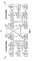
- FIG. 1 shows a transmitter system and a receiver system in a MIMO system
- FIG. 2 shows a process for performing SIC receiver processing on N R received symbol streams to recover N T transmitted symbol streams
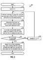
- FIG. 3 shows a process for determining the data rates for the transmit antennas and the best ordering for a SIC receiver with selection diversity
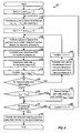
- FIG. 4 shows a specific implementation of the process in FIG. 3 ;
- FIG. 5 shows a block diagram of a transmitter subsystem
- FIG. 6 shows a block diagram of a receiver subsystem.
- the techniques described herein for supporting SIC receiver processing with selection diversity may be used in various communication systems, such as a MIMO system, a MIMO system that employs orthogonal frequency division multiplexing (i.e., a MIMO-OFDM system), and so on.
- MIMO-OFDM system orthogonal frequency division multiplexing
- these techniques are described specifically for a MMO system.
- the following description assumes that (1) one data stream is transmitted from each transmit antenna and (2) each data stream is independently processed at a transmitter and may be individually recovered at a receiver.
- FIG. 1 shows a block diagram of a transmitter system 110 and a receiver system 150 in a MIMO system 100.
- Transmitter system 110 and receiver system 150 may each be implemented in an access point (i.e., a base station) or a user terminal in the MIMO system.
- a transmit (TX) data processor 120 receives traffic data from a data source 112 for up to N T data streams. Each data stream is designated for transmission from a respective transmit antenna. TX data processor 120 formats, codes, interleaves, and modulates the traffic data for each data stream to obtain a corresponding stream of modulation symbols (or "data symbols"). TX data processor 120 may further multiplex pilot symbols with the data symbols. TX data processor 120 provides N T symbol streams to N T transmitter units (TMTR) 122a through 122t. Each symbol stream may include any combination of data and pilot symbols. Each transmitter unit 122 processes its symbol stream and provides a modulated signal suitable for transmission over the wireless communication link. N T modulated signals from transmitter units 122a through 122t are transmitted from N T antennas 124a through 124t, respectively.
- the transmitted modulated signals are received by N R antennas 152a through 152r, and the received signal from each antenna 152 is provided to a respective receiver unit (RCVR) 154.
- Each receiver unit 154 conditions and digitizes its received signal and provides a stream of received symbols.
- a receive (RX) spatial/data processor 160 receives the N R received symbol streams from N R receiver units 154a through 154r, processes these received symbol streams using SIC receiver processing, and provides N T decoded data streams. The processing by RX spatial/data processor 160 is described in detail below.
- RX spatial/data processor 160 further estimates the channel response between the N T transmit antennas and the N R receive antennas, the received SNRs and/or the post-detection SNRs of the symbol streams, and so on (e.g., based on the received pilot symbols). RX spatial/data processor 160 may use the channel response estimate to perform spatial or space-time processing, as described below.
- Controllers 130 and 170 direct the operation at transmitter system 110 and receiver system 150, respectively.
- Memory units 132 and 172 provide storage for program codes and data used by controllers 130 and 170, respectively.
- controller 170 receives the channel response estimates and the SNR estimates from RX spatial/data processor 160, determines the data rate to use for each transmit antenna and the specific ordering for recovering the symbol streams, and provides feedback information for transmitter system 110.
- the feedback information may include, for example, the data rates for the N T transmit antennas.
- the feedback information is processed by a TX data processor 184, conditioned by transmitter units 154a through 154r, and transmitted back to transmitter system 110.
- the modulated signals from receiver system 150 are received by antennas 124, conditioned by receiver units 122, and processed by an RX data processor 140 to recover the feedback information sent by receiver system 150.
- Controller 130 receives and uses the recovered feedback information to (1) control the data rate for the symbol stream sent from each transmit antenna, (2) determine the coding and modulation scheme to use for each data stream, and (3) generate various controls for TX data processor 120.
- controller 130 obtains the channel response estimates for the MIMO channel and the noise variance (i.e., noise floor) at receiver system 150. Controller 130 then determines the data rate to use for each transmit antenna and provides various controls for TX data processor 120. Transmitter system 110 may obtain the channel response estimates based on pilot symbols sent by receiver system 150. The receiver noise floor may be estimated by receiver system 150 and sent to transmitter system 110 as feedback information.
- the noise variance i.e., noise floor
- the data rates for the transmit antennas and the ordering for recovering the symbol streams may be determined by the transmitter system, the receiver system, or both.
- the following description is for the embodiment whereby the data rates and the ordering are determined by the receiver system and communicated to the transmitter system.
- each transmitted symbol stream is received by all N R receive antennas at different amplitudes and phases, as determined by the complex channel gains between the transmit antenna for that symbol stream and the N R receive antennas.
- Each received symbol stream includes a component of each of the N T transmitted symbol streams.
- the N R received symbol streams would collectively include all N T transmitted symbols streams, and instances of each of the N T transmitted symbol streams can be found in each of the N R received symbol streams.
- the SIC receiver processing technique which is also referred to as successive nulling/equalization and interference cancellation processing technique, can process the N R received symbol streams to obtain the N T transmitted symbol streams.
- the SIC receiver processing technique successively recovers the transmitted symbol streams in multiple stages, one stage for each symbol stream. Each stage recovers one transmitted symbol stream. As each symbol stream is recovered, the interference it causes to the remaining not yet recovered symbol streams is estimated and canceled from the received symbol streams to obtain "modified" symbol streams. The modified symbol streams are then processed by the next stage to recover the next transmitted symbol stream. If the symbol streams can be recovered without error (or with minimal errors) and if the channel response estimates are reasonably accurate, then the interference due to the recovered symbol streams can be effectively canceled. Each subsequently recovered symbol stream thus experiences less interference and may achieve a higher post-detection SNR than without interference cancellation.
- FIG. 2 shows a flow diagram of a process 200 for performing SIC receiver processing on N R received symbol streams to recover N T transmitted symbol streams.
- the SIC receiver performs spatial or space-time processing on the N R received symbol streams (as described below) to separate out the N T transmitted symbol streams (step 214).
- the spatial or space-time processing provides ( N T - ⁇ +1) detected symbol streams, which are estimates of the transmitted symbol streams not yet recovered.
- One of the detected symbol streams is selected for recovery (step 216).
- This detected symbol stream is then processed (e.g., demodulated, deinterleaved, and decoded) to obtain a decoded data stream, which is an estimate of the data stream for the symbol stream being recovered in this stage (step 218).
- a determination is then made whether or not all transmitted symbol streams have been recovered (step 220). If the answer is 'yes' (i.e., if ⁇ N T ), then process 200 terminates. Otherwise, the interference due to the just recovered symbol stream is estimated (step 222). To obtain the interference estimate, the decoded data stream is reencoded, interleaved, and re-modulated with the same coding, interleaving, and modulation schemes used at the transmitter for this data stream to obtain a "remodulated" symbol stream, which is an estimate of the transmitted symbol stream just recovered. The remodulated symbol stream is then processed with the channel response estimates to obtain N R interference components, which are estimates of the interference due to the just recovered symbol stream on the remaining not yet recovered symbol streams.
- the N R interference components are then subtracted from the N R received symbol streams to obtain N R modified symbol streams (step 224). These modified symbol streams represent the streams that would have been received if the just recovered symbol stream had not been transmitted (i.e., assuming that the interference cancellation was effectively performed).
- Steps 214 through 218 are then repeated on the N R modified symbol streams to recover another transmitted symbol stream. Steps 214 through 218 are repeated for each transmitted symbol stream to be recovered. Steps 222 through 226 are performed if there is another transmitted symbol stream to recover.
- the input symbol streams are the N R received symbol streams.
- the input symbol streams are the N R modified symbol streams from the preceding stage. The processing for each stage proceeds in similar manner.
- N T ! possible orderings of recovering N T transmitted symbol streams there are N T ! possible orderings of recovering N T transmitted symbol streams. This is because any one of N T detected symbol streams may be recovered in the first stage, any one of (N T -1) detected symbol streams may be recovered in the second stage, and so on, and only one detected symbol stream is available and recovered in the last stage.
- the SIC receiver can evaluate each of the N T ! possible orderings and select the best ordering for use.
- the index k is used for the N T ! orderings, where k ⁇ ⁇ 1, 2, ... N T ! ⁇ .
- the order in which the N T transmit antennas are recovered is represented as ⁇ k 1 , k 2 , ... k NT ⁇ , where k ⁇ for ⁇ 1, 2, ... N T ⁇ denotes the transmit antenna to be recovered in stage ⁇ , of ordering k .
- Equation (2) assumes that the symbol streams recovered in the prior ( ⁇ -1) stages are cancelled.
- the dimensionality of the channel response matrix H is thus successively reduced by one column for each stage as a transmitted symbol stream is recovered and canceled.
- each of the ( N T - ⁇ +1) transmitted symbol streams that have not yet been recovered may be "isolated” or "detected” by filtering the N R modified symbol streams y ⁇ k ⁇ with a matched filter for that symbol stream.
- the matched filter for the symbol stream sent from transmit antenna k n for n ⁇ ⁇ , ⁇ +1, ... N T ⁇ , has a unit-norm vector w k n of N R filter coefficients.
- the transmitted symbol streams from the other ( ⁇ -1) transmit antennas, k n for n ⁇ ⁇ 1, 2, ... ⁇ -1 ⁇ have already been recovered in prior stages and canceled from the modified symbol streams y ⁇ k ⁇ .
- the vector w k n does not need to be orthogonal to ⁇ h k m ⁇ , for m e ⁇ 1, 2, ... ⁇ -1 ⁇ .
- the matched filter vector w k n may be derived based on various spatial and space-time processing techniques.
- the spatial processing techniques include a zero-forcing technique (which is also referred to as a channel correlation matrix inversion (CCMI) technique) and a minimum mean square error (MMSE) technique.
- the space-time processing techniques include a decision feedback equalizer (DFE), an MMSE linear equalizer (MMSE-LE), and a maximum-likelihood sequence estimator (MLSE).
- the matched filter response w k n is derived with a linear zero-forcing equalizer, which performs spatial processing by projecting the received symbol streams over an interference-free sub-space to obtain the detected symbol streams.
- the matched filter response w k n for the symbol stream sent from transmit antenna k n is then the column of W ⁇ k ⁇ corresponding to transmit antenna k n .
- the symbol stream sent from transmit antenna k ⁇ is selected for recovery.
- the detected symbol stream x ⁇ k ⁇ comprises the transmitted symbol stream x k ⁇ plus post-detection or filtered noise w ⁇ k ⁇ H ⁇ n ⁇ .
- the post-detection SNR is indicative of the SNR achieved for a detected symbol stream after the receiver processing to remove interference from the other symbol streams.
- the improvement in the post-detection SNR comes from the fact that the norm of w k ⁇ in equation (7) decreases with each stage.
- the analysis described above may also be performed based on other space or space-time processing techniques.
- the zero-forcing (CCMI), MMSE, DFE, and MMSE-LE techniques are described in detail in commonly assigned U.S. Patent Application Serial No. 09/993,087 , entitled “Multiple-Access Multiple-Input Multiple-Output (MIMO) Communication System,” filed November 6,2001.
- the SIC receiver can evaluate each of the N T ! possible orderings of recovering the transmitted symbol streams. For each ordering k , the SIC receiver can compute a set of N T post-detection SNRs for the N T transmit antennas. The SIC receiver can then select one of the N T ! possible orderings for use based on one or more criteria. For example, the selection may be based on overall spectral efficiency.
- Spectral efficiency is equal to data rate normalized by the system bandwidth, and is given in units of bits per second per Hertz (bps/Hz).
- the receiver can compute the overall spectral efficiency for each of the N T ! possible orderings. The receiver can then select the ordering with the highest overall spectral efficiency for use (i.e., max ⁇ C total , k ⁇ ).
- the MIMO system may be designed to support a set of discrete data rates, which includes non-zero data rates as well as the null or zero data rate.
- Each non-zero data rate may be associated with a particular coding scheme, a particular modulation scheme, and so on.
- Each non-zero data rate is further associated with a particular minimum SNR required to achieve the desired level of performance (e.g., 1% packet error rate) for a non-fading, AWGN channel.
- the required SNR for each non-zero data rate may be determined based on computer simulation, empirical measurements, and so on, as is known in the art.
- a look-up table may be used to store the supported data rates and their required SNRs.
- the selected ordering (e.g., the one with the highest overall spectral efficiency) is associated with a set of N T post-detection SNRs for the N T transmit antennas.
- the highest data rate that may be reliably transmitted from each transmit antenna is determined by its post-detection SNR.
- the post-detection SNR for each transmit antenna should be equal to or higher than the required SNR for the data rate selected for that transmit antenna.
- each transmit antenna may be turned off (i.e., shut off) if its post-detection SNR is lower than the required SNR for the lowest non-zero data rate r min supported by the MIMO system.
- the symbol streams sent from other transmit antennas may experience less interference and may be able to achieve higher post-detection SNRs. Improved performance in terms of higher data rates and/or greater reliability may be achieved.
- N T transmit antennas there are N T different antenna configurations, where each configuration corresponds to a specific number of transmit antennas that is turned on.
- the N T antenna configurations are given in column 1 of Table 1, and the number of active transmit antennas for each configuration is given in column 2.
- Each antenna configuration is associated with one or more antenna patterns, where each antenna pattern indicates which transmit antennas are turned on and which transmit antennas are turned off.
- N T possible antenna patterns for the configuration with ( N T -1) transmit antennas turned on there are: (1) only one antenna pattern for the configuration with all N T transmit antennas turned on, (2) N T possible antenna patterns for the configuration with ( N T -1) transmit antennas turned on, (3) N T ⁇ ( N T -1)/2 possible antenna patterns for the configuration with ( N T - 2) transmit antennas turned on, and so on, and (4) N T possible antenna patterns for the configuration with only one transmit antenna turned on.
- the number of antenna patterns for each configuration is given in column 3 of Table 1.
- the number of possible orderings for that antenna pattern is dependent on the active transmit antennas that are turned on and is not dependent on the inactive transmit antennas that are turned off.
- there are N T ! possible orderings for recovering the N T active transmit antennas as described above.
- the computation proceeds in similar manner for other configurations.
- For configuration N T with one transmit antenna turned on there is only one possible ordering for recovering the single active transmit antenna for each antenna pattern of configuration N T .
- the number of orderings for each antenna pattern of each configuration is given in column 4 of Table 1.
- the number of orderings for each antenna configuration is obtained by multiplying the number of antenna patterns for that configuration with the number of orderings for each antenna pattern of that configuration. This is given in column 5 of Table 1.
- each transmit antenna can be turned on or off independently, then there are 2 N T possible antenna patterns.
- N T 4
- the pattern with all zeros is not evaluated if at least one transmit antenna is used for data transmission.
- the SIC receiver For each active antenna pattern m with N act , m transmit antennas that are turned on, the SIC receiver can evaluate the N act,m ! possible orderings of recovering the symbol streams sent from the N act,m active transmit antennas. For each of the N act,m ! possible orderings for a given active antenna pattern, the SIC receiver can (1) obtain a set of post-detection SNRs for the active transmit antennas in that pattern m (the post-detection SNR for a transmit antenna that is turned off may be set to zero) and (2) compute the overall spectral efficiency for that ordering/pattern. The SIC receiver can then select the ordering/pattern with the highest overall spectral efficiency among the N total possible orderings.
- the SIC receiver with selection diversity may evaluate the N total possible orderings based on the following pseudo-code:
- each active antenna pattern m defines a specific set of N act,m active transmit antennas and ( N T -N act,m ) inactive transmit antennas, where N act,m is dependent on the antenna pattern m.
- Each ordering k defines a specific order in which the N act,m active transmit antennas are recovered. The ordering may be represented as ⁇ k 1 , k 2 , ... k ⁇ , ... k N act,m ⁇ where the ( N T - N act,m ) inactive transmit antennas are not included in the set and k ⁇ , is the transmit antenna to recover in stage ⁇ of ordering k .
- a simplified method is provided herein that evaluates at most N T ! possible orderings to determine the data rates for the transmit antennas and the best ordering for the SIC receiver with selection diversity. This represents a substantial reduction over the N total possible orderings evaluated by the brute-force method.
- the simplification is based on a lemma which states that, for any specific ordering with a zero data rate for at least one transmit antenna, there exists another ordering with non-zero data rates for all transmit antennas with the same or greater throughput. This lemma indicates that the active antenna pattern of all ones ('111...1') provides the highest throughput of all (2 N T -1) active antenna patterns and is the only one that needs to be evaluated.
- the transmit antennas are given indices of 1, 2, ... N T and are recovered based on the ordering ⁇ 1, 2, ... N T ⁇ , where transmit antenna 1 is recovered first and transmit antenna N T is recovered last.
- Transmit antenna i is switched off, where 1 ⁇ i ⁇ N T .
- the data rates supported by the N T transmit antennas are denoted as ⁇ r 1 , r 2 , ..., r i -1 , 0, r i +1 , ..., r N T ⁇ . These data rates are obtained based on the post-detection SNRs for the transmit antennas.
- each transmit antenna n is dependent only on the data rates of subsequently recovered transmit antennas ⁇ n +1, n + 2, ... N T ⁇ and is not dependent on the data rates of prior recovered transmit antennas ⁇ 1, 2, ... n -1 ⁇ .
- This property assumes that the interference due to the prior recovered transmit antennas is effectively canceled and has no impact on transmit antenna n .
- the N T transmit antennas in the original ordering can be rearranged so that transmit antenna i is now the first antenna and the original ordering is otherwise preserved. This rearrangement does not impact the data rates for any of the ( N T -1) active transmit antennas.
- the new antenna ordering is then ( i , 1, 2, ..., i -1, i +1, ..., N T ⁇ and the associated data rates are (0, r 1 , r 2 , ..., r i -1 , r i +1 , ..., r N T ⁇ .
- the data rate used for transmit antenna i does not affect the data rates for the other ( N T -1) transmit antennas, so long as transmit antenna i can be recovered error-free or with low error and its interference can be canceled.
- a non-zero data rate may then be used for transmit antenna i and this data rate is dependent on the data rates for the other ( N T -1) transmit antennas.
- the data rates achievable by the original ordering with transmit antenna i turned off can also be achieved by the new ordering with a non-zero rate for transmit antenna i .
- the proof of the lemma may be extended in similar manner to cases where multiple transmit antennas are turned off.
- FIG. 3 shows a flow diagram of a process 300 for determining the data rates for the N T transmit antennas and the ordering for a SIC receiver with selection diversity.
- the index k used for the possible orderings is set to 1 (step 310).
- Ordering k is evaluated using SIC receiver processing to obtain N T post-detection SNRs for N T transmit antennas (312).
- the data rate for each transmit antenna is then determined based on its post-detection SNR (step 314).
- the data rate for each transmit antenna may be one of the discrete data rates supported by the system.
- a zero data rate is used for each transmit antenna with a post-detection SNR worse than the minimum required SNR, which may be the required SNR for the lowest non-zero data rate supported by the system.
- N T data rates are obtained for N T transmit antennas for ordering k, where any of the N T data rates may be the zero data rate.
- An overall data rate is computed for ordering k based on the N T data rates
- Process 300 may be performed by receiver system 150 and the data rates for the selected ordering may be sent to transmitter system 110 as feedback information. Alternatively or additionally, process 300 may be performed by transmitter system 110. In any case, transmitter system 110 processes up to N T symbol streams at the data rates for the selected ordering and transmits these symbol streams from the N T transmit antennas. Receiver system 150 recovers the transmitted symbol streams in accordance with the selected ordering.
- FIG. 4 shows a flow diagram of a process 400 for determining the data rates for the transmit antennas and the ordering for a SIC receiver with selection diversity.
- Process 400 is a specific implementation of process 300 in FIG. 3 . Initially, the ordering index k is set to 1 and the variable r besr for the best overall data rate is set to 0 (step 410).
- the order of recovering the transmit antennas ⁇ k 1 , k 2 , ... k N T ⁇ is first determined (step 420).
- the stage index ⁇ is set to 1 and the variable r total for the overall data rate for ordering k is set to 0 (step 422).
- spatial or space-time processing is first performed on the N R input symbol streams y ⁇ k ⁇ to obtain the detected symbol stream x ⁇ k ⁇ for transmit antenna k ⁇ to be recovered in that stage (step 430).
- the post-detection SNR for transmit antenna k ⁇ is then computed as shown in equation (7) (step 432).
- the data rate r k ⁇ for transmit antenna k ⁇ is determined based on its post-detection SNR (e.g., as shown in equation (8) or using a look-up table) (step 434).
- a determination is then made whether or not all transmit antennas have been recovered for ordering k (step 440). If the answer is 'no', then the interference due to the just recovered symbol stream from transmit antenna k ⁇ is estimated and canceled from the input symbol streams y ⁇ k ⁇ to obtain the input symbol streams y ⁇ k ⁇ + 1 for the next stage (step 442). The stage index is then updated as ⁇ ⁇ +1 (step 444), and the process returns to step 430 to recover another symbol stream for another transmit antenna.
- one symbol stream may be transmitted from all subbands of each transmit antenna using OFDM processing.
- the post-detection SNR may be determined for each subband of each transmit antenna.
- the post-detection SNRs of all subbands of each transmit antenna may be combined to obtain the post-detection SNR for that transmit antenna.
- the ordering and data rates may then be selected based on the post-detection SNRs for the transmit antennas as described above.
- FIG. 5 shows a block diagram of a transmitter subsystem 500, which is an embodiment of the transmitter portion of transmitter system 110 in FIG. 1 .
- TX data processor 120 includes a demultiplexer (Demux) 510, N T encoders 512a through 512t, N T channel interleavers 514a through 514t, N T symbol mapping units 516a through 516t, and N T multiplexers (Muxes) 518a through 518t (i.e., one set of encoder, channel interleaver, symbol mapping unit, and multiplexer for each of the N T transmit antennas).
- Demultiplexer 510 demultiplexes the traffic data (i.e., the information bits) into up to N T data streams.
- One data stream is provided for each transmit antenna with a non-zero data rate.
- Each data stream is provided at the data rate selected for the transmit antenna, as indicated by the data rate control.
- Each encoder 512 receives and encodes a respective data stream based on the selected coding scheme (as indicated by the coding control) and provides code bits.
- the coding increases the reliability of the data transmission.
- the selected coding scheme may include any combination of CRC coding, convolutional coding, turbo coding, block coding, and so on.
- Each encoder 512 provides code bits to a respective channel interleaver 514, which interleaves the code bits based on a particular interleaving scheme. If the interleaving is dependent on data rate, then controller 130 provides an interleaving control (as indicated by the dashed line) to channel interleaver 514.
- the interleaving provides time, frequency, and/or spatial diversity for the code bits.
- Each channel interleaver 514 provides interleaved bits to a respective symbol mapping unit 516, which maps (i.e., modulates) the interleaved bits based on the selected modulation scheme (as indicated by the modulation control) and provides modulation symbols.
- Each modulation symbol is a complex value in a signal constellation defined by the selected modulation scheme.
- Each symbol mapping unit 516 provides modulation symbols (or "data symbols") to a respective multiplexer 518, which multiplexes the data symbols with pilot symbols using, for example, time division multiplex (TDM) or code division multiplex (CDM).
- Multiplexers 518a through 518t provide up to N T symbol streams to transmitter units 122a through 122t, which process these symbol streams to obtain modulated signals.
- Other designs for transmitter subsystem 500 may also be used and are within the scope of the invention.
- Controller 130 may perform various functions for data transmission from the N T transmit antennas. For example, controller 130 may receive the N T data rates for the N T transmit antennas (where one or more of these data rates may be zero) as feedback information from receiver system 150. Controller 130 may then generate the data rate, coding, interleaving, and modulation controls for the processing units within TX data processor 120. Alternatively, controller 130 may receive the channel response estimates, evaluate the possible orderings, select the ordering and data rates for the transmit antennas, and generate the controls for the processing units within TX data processor 120.
- FIG. 6 shows a block diagram of a receiver subsystem 600, which is an embodiment of the receiver portion of receiver system 150 in FIG. 1 .
- RX MIMO/data processor 160 includes N T successive (i.e., cascaded) receiver processing stages 610a through 610t, one stage for each of the N T transmit antennas.
- Each receiver processing stage 610 (except for the last stage 610t) includes a spatial processor 620, an RX data processor 630, and an interference canceller 640.
- the last stage 610t includes only spatial processor 620t and RX data processor 630t.
- spatial processor 620a receives the N R received symbol streams y , performs spatial or space-time processing (e.g., zero-forcing) on the received symbol streams, and provides the detected symbol stream x ⁇ k 1 for the first transmit antenna in the selected ordering k .
- RX data processor 630a further processes (e.g., demodulates, deinterleaves, and decodes) the detected symbol stream x ⁇ k 1 to obtain a decoded data stream d ⁇ k 1 , which is an estimate of the data stream d k 1 for the symbol stream x k 1 being recovered.
- interference canceller 640a receives the N R received symbol streams y and the decoded data stream d ⁇ k 1 .
- Interference canceller 640a performs the processing (e.g., encoding, interleaving, and symbol mapping) to obtain a remodulated symbol stream, x ′ ⁇ k 1 , which is an estimate of the symbol stream x k 1 just recovered.
- the remodulated symbol stream x ′ ⁇ k 1 is further processed to obtain estimates of the interference components i ⁇ k 1 due to the just recovered symbol stream.
- the interference components i ⁇ k 1 are then subtracted from the first stage's input symbol streams y to obtain N R modified symbol streams y ⁇ k 2 , which include all but the cancelled interference components.
- the modified symbol streams y ⁇ k 2 are then provided to the second stage.
- the spatial processor for that stage receives and processes the N R modified symbol streams y ⁇ k ⁇ from the interference canceller in the preceding stage to obtain the detected symbol stream x ⁇ k ⁇ for that stage.
- the detected symbol stream x ⁇ k ⁇ is then processed by the RX data processor to obtain the decoded data stream d ⁇ k ⁇ .
- the interference canceller in that stage receives the N R modified symbol streams y ⁇ k ⁇ from the interference canceller in the preceding stage and the decoded data stream d ⁇ k ⁇ from the RX data processor within the same stage, derives the N R interference components i ⁇ k ⁇ due to the symbol stream x k ⁇ recovered by that stage, and provides N R modified symbol streams y ⁇ k ⁇ + 1 for the next stage.
- a channel estimator 650 also receives the N R received symbol streams y , estimates the channel response matrix H and the noise variance ⁇ 2 based on the received pilot symbols, and provides the channel response and noise estimates (e.g., ⁇ and ⁇ 2 ).
- the estimated channel response matrix ⁇ is used for space or space-time processing by all stages, as described above.
- Controller 170 receives the channel response and noise estimates, evaluates up to N T ! possible orderings, computes the set of post-detection SNRs for each ordering, and determines the best ordering and the data rates for the selected ordering.
- Memory unit 172 stores a look-up table (LUT) 660 of supported data rates and their required SNRs.
- LUT look-up table
- Look-up table 660 is used by controller 170 to determine the data rate for each transmit antenna based on its post-detection SNR. Controller 170 provides the selected ordering to RX data processor 160 and may provide the data rates for the selected ordering as feedback information to transmitter system 110.
- the techniques described herein for supporting SIC receiver processing with selection diversity may be implemented by various means. For example, these techniques may be implemented in hardware, software, or a combination thereof.
- the processing units for SIC receiver processing with selection diversity e.g., TX data processor 120 and controller 130 at transmitter system 110, and RX spatial/data processor 160 and controller 170 at receiver system 150
- the processing units for SIC receiver processing with selection diversity may be implemented within one or more application specific integrated circuits (ASICs), digital signal processors (DSPs), digital signal processing devices (DSPDs), programmable logic devices (PLDs), field programmable gate arrays (FPGAs), processors, controllers, micro-controllers, microprocessors, other electronic units designed to perform the functions described herein, or a combination thereof.
- ASICs application specific integrated circuits
- DSPs digital signal processors
- DSPDs digital signal processing devices
- PLDs programmable logic devices
- FPGAs field programmable gate arrays
- processors controllers, micro-control
- the SIC receiver processing with selection diversity may be implemented at the transmitter and receiver systems with modules (e. g. , procedures, functions, and so on) that perform the functions described herein.
- the software codes may be stored in a memory unit (e. g. , memory units 132 and 172 in FIG. 1 ) and executed by a processor (e. g. , controllers 130 and 170).
- the memory unit may be implemented within the processor or external to the processor, in which case it can be communicatively coupled to the processor via various means as is known in the art.
- the previous description of the disclosed embodiments is provided to enable any person skilled in the art to make or use the present invention.
- a method of controlling data transmission in a multiple-input multiple-output (MIMO) communication system comprising:
Landscapes
- Engineering & Computer Science (AREA)
- Computer Networks & Wireless Communication (AREA)
- Signal Processing (AREA)
- Quality & Reliability (AREA)
- Radio Transmission System (AREA)
- Mobile Radio Communication Systems (AREA)
Applications Claiming Priority (2)
| Application Number | Priority Date | Filing Date | Title |
|---|---|---|---|
| US10/670,079 US6917821B2 (en) | 2003-09-23 | 2003-09-23 | Successive interference cancellation receiver processing with selection diversity |
| EP04781672A EP1665548B1 (de) | 2003-09-23 | 2004-08-17 | Sukzessive störungsaufhebungs-empfängerverarbeitung mit auswahl-diversität |
Related Parent Applications (1)
| Application Number | Title | Priority Date | Filing Date |
|---|---|---|---|
| EP04781672.3 Division | 2004-08-17 |
Publications (2)
| Publication Number | Publication Date |
|---|---|
| EP2237433A2 true EP2237433A2 (de) | 2010-10-06 |
| EP2237433A3 EP2237433A3 (de) | 2012-03-21 |
Family
ID=34393440
Family Applications (2)
| Application Number | Title | Priority Date | Filing Date |
|---|---|---|---|
| EP10170338A Withdrawn EP2237433A3 (de) | 2003-09-23 | 2004-08-17 | Sukzessive Störungsaufhebungs-Empfängerverarbeitung mit Auswahl-Diversität |
| EP04781672A Expired - Lifetime EP1665548B1 (de) | 2003-09-23 | 2004-08-17 | Sukzessive störungsaufhebungs-empfängerverarbeitung mit auswahl-diversität |
Family Applications After (1)
| Application Number | Title | Priority Date | Filing Date |
|---|---|---|---|
| EP04781672A Expired - Lifetime EP1665548B1 (de) | 2003-09-23 | 2004-08-17 | Sukzessive störungsaufhebungs-empfängerverarbeitung mit auswahl-diversität |
Country Status (15)
| Country | Link |
|---|---|
| US (3) | US6917821B2 (de) |
| EP (2) | EP2237433A3 (de) |
| JP (2) | JP4690325B2 (de) |
| KR (1) | KR100784744B1 (de) |
| CN (2) | CN100530981C (de) |
| AR (1) | AR047022A1 (de) |
| AT (1) | ATE525809T1 (de) |
| AU (1) | AU2004306689B2 (de) |
| BR (1) | BRPI0414656A (de) |
| CA (1) | CA2539966C (de) |
| IL (2) | IL174456A (de) |
| MX (1) | MXPA06003322A (de) |
| MY (1) | MY144667A (de) |
| RU (1) | RU2340099C2 (de) |
| WO (1) | WO2005036799A2 (de) |
Families Citing this family (133)
| Publication number | Priority date | Publication date | Assignee | Title |
|---|---|---|---|---|
| US7952511B1 (en) | 1999-04-07 | 2011-05-31 | Geer James L | Method and apparatus for the detection of objects using electromagnetic wave attenuation patterns |
| US9130810B2 (en) | 2000-09-13 | 2015-09-08 | Qualcomm Incorporated | OFDM communications methods and apparatus |
| US7295509B2 (en) | 2000-09-13 | 2007-11-13 | Qualcomm, Incorporated | Signaling method in an OFDM multiple access system |
| EP1392069B1 (de) * | 2002-02-18 | 2015-04-01 | Sony Corporation | Drahtloses kommunikationssystem, drahtlose kommunikationseinrichtung und drahtloses kommunikationsverfahren und computerprogramm |
| DE60332893D1 (de) * | 2002-04-25 | 2010-07-22 | Imec | CDMA Empfang-übertragungstechniken für Funksysteme mit Mehrfacheingängen und Mehrfachausgängen (MIMO) |
| US7440510B2 (en) * | 2003-09-15 | 2008-10-21 | Intel Corporation | Multicarrier transmitter, multicarrier receiver, and methods for communicating multiple spatial signal streams |
| US6917821B2 (en) * | 2003-09-23 | 2005-07-12 | Qualcomm, Incorporated | Successive interference cancellation receiver processing with selection diversity |
| KR100995031B1 (ko) * | 2003-10-01 | 2010-11-19 | 엘지전자 주식회사 | 다중입력 다중출력 시스템에 적용되는 신호 전송 제어 방법 |
| US9026070B2 (en) | 2003-12-18 | 2015-05-05 | Qualcomm Incorporated | Low-power wireless diversity receiver with multiple receive paths |
| US7649833B2 (en) * | 2003-12-29 | 2010-01-19 | Intel Corporation | Multichannel orthogonal frequency division multiplexed receivers with antenna selection and maximum-ratio combining and associated methods |
| US7570953B2 (en) * | 2004-01-12 | 2009-08-04 | Intel Corporation | Multicarrier communication system and methods for link adaptation using uniform bit loading and subcarrier puncturing |
| US7333556B2 (en) * | 2004-01-12 | 2008-02-19 | Intel Corporation | System and method for selecting data rates to provide uniform bit loading of subcarriers of a multicarrier communication channel |
| JP4367659B2 (ja) * | 2004-03-26 | 2009-11-18 | 日本電気株式会社 | 無線通信機 |
| JP4228014B2 (ja) * | 2004-04-05 | 2009-02-25 | パナソニック株式会社 | 無線通信装置および無線通信方法 |
| US20050265225A1 (en) * | 2004-05-11 | 2005-12-01 | Orion Microelectronics Corporation | MIMO system and mode table |
| US7319345B2 (en) * | 2004-05-18 | 2008-01-15 | Rambus Inc. | Wide-range multi-phase clock generator |
| US9148256B2 (en) * | 2004-07-21 | 2015-09-29 | Qualcomm Incorporated | Performance based rank prediction for MIMO design |
| US7567621B2 (en) * | 2004-07-21 | 2009-07-28 | Qualcomm Incorporated | Capacity based rank prediction for MIMO design |
| US9137822B2 (en) | 2004-07-21 | 2015-09-15 | Qualcomm Incorporated | Efficient signaling over access channel |
| US7684753B2 (en) * | 2004-07-21 | 2010-03-23 | Nokia Corporation | Method and device for transmission parameter selection in mobile communications |
| US7899497B2 (en) * | 2004-08-18 | 2011-03-01 | Ruckus Wireless, Inc. | System and method for transmission parameter control for an antenna apparatus with selectable elements |
| US7933628B2 (en) * | 2004-08-18 | 2011-04-26 | Ruckus Wireless, Inc. | Transmission and reception parameter control |
| US7433434B2 (en) * | 2004-10-01 | 2008-10-07 | General Dynamics C4 Systems, Inc. | Communication channel tracking apparatus |
| JP4763703B2 (ja) * | 2004-10-01 | 2011-08-31 | エージェンシー フォー サイエンス, テクノロジー アンド リサーチ | 信号ベクトルの決定方法及びシステム、並びにコンピュータプログラム要素 |
| US8792414B2 (en) | 2005-07-26 | 2014-07-29 | Ruckus Wireless, Inc. | Coverage enhancement using dynamic antennas |
| KR100630131B1 (ko) * | 2004-12-31 | 2006-09-27 | 삼성전자주식회사 | 무선 근거리 네트워크에서 방송 서비스의 서비스 품질을보장하는 엑세스 포인트 장치 |
| ATE424063T1 (de) * | 2005-02-07 | 2009-03-15 | Ericsson Telefon Ab L M | Transferraten-messungen |
| US9246560B2 (en) | 2005-03-10 | 2016-01-26 | Qualcomm Incorporated | Systems and methods for beamforming and rate control in a multi-input multi-output communication systems |
| US9154211B2 (en) | 2005-03-11 | 2015-10-06 | Qualcomm Incorporated | Systems and methods for beamforming feedback in multi antenna communication systems |
| US8446892B2 (en) | 2005-03-16 | 2013-05-21 | Qualcomm Incorporated | Channel structures for a quasi-orthogonal multiple-access communication system |
| US9143305B2 (en) | 2005-03-17 | 2015-09-22 | Qualcomm Incorporated | Pilot signal transmission for an orthogonal frequency division wireless communication system |
| US9520972B2 (en) | 2005-03-17 | 2016-12-13 | Qualcomm Incorporated | Pilot signal transmission for an orthogonal frequency division wireless communication system |
| US9461859B2 (en) | 2005-03-17 | 2016-10-04 | Qualcomm Incorporated | Pilot signal transmission for an orthogonal frequency division wireless communication system |
| US9184870B2 (en) | 2005-04-01 | 2015-11-10 | Qualcomm Incorporated | Systems and methods for control channel signaling |
| US9408220B2 (en) | 2005-04-19 | 2016-08-02 | Qualcomm Incorporated | Channel quality reporting for adaptive sectorization |
| US9036538B2 (en) | 2005-04-19 | 2015-05-19 | Qualcomm Incorporated | Frequency hopping design for single carrier FDMA systems |
| EP1722500A1 (de) * | 2005-05-13 | 2006-11-15 | Interuniversitair Microelektronica Centrum ( Imec) | Verfahren für drahtlose Kommunikation |
| KR101124932B1 (ko) | 2005-05-30 | 2012-03-28 | 삼성전자주식회사 | 어레이 안테나를 이용하는 이동 통신 시스템에서의 데이터송/수신 장치 및 방법 |
| US8879511B2 (en) | 2005-10-27 | 2014-11-04 | Qualcomm Incorporated | Assignment acknowledgement for a wireless communication system |
| US8842693B2 (en) | 2005-05-31 | 2014-09-23 | Qualcomm Incorporated | Rank step-down for MIMO SCW design employing HARQ |
| US8565194B2 (en) | 2005-10-27 | 2013-10-22 | Qualcomm Incorporated | Puncturing signaling channel for a wireless communication system |
| US8611284B2 (en) | 2005-05-31 | 2013-12-17 | Qualcomm Incorporated | Use of supplemental assignments to decrement resources |
| US8462859B2 (en) | 2005-06-01 | 2013-06-11 | Qualcomm Incorporated | Sphere decoding apparatus |
| US9179319B2 (en) | 2005-06-16 | 2015-11-03 | Qualcomm Incorporated | Adaptive sectorization in cellular systems |
| US8064837B2 (en) * | 2005-06-16 | 2011-11-22 | Qualcomm Incorporated | Method and apparatus for optimum selection of MIMO and interference cancellation |
| US8599945B2 (en) * | 2005-06-16 | 2013-12-03 | Qualcomm Incorporated | Robust rank prediction for a MIMO system |
| US8885628B2 (en) | 2005-08-08 | 2014-11-11 | Qualcomm Incorporated | Code division multiplexing in a single-carrier frequency division multiple access system |
| US20070041457A1 (en) | 2005-08-22 | 2007-02-22 | Tamer Kadous | Method and apparatus for providing antenna diversity in a wireless communication system |
| US9209956B2 (en) | 2005-08-22 | 2015-12-08 | Qualcomm Incorporated | Segment sensitive scheduling |
| US8644292B2 (en) | 2005-08-24 | 2014-02-04 | Qualcomm Incorporated | Varied transmission time intervals for wireless communication system |
| US7672256B2 (en) * | 2005-08-29 | 2010-03-02 | Interdigital Technology Corporation | Wireless communication method and apparatus for generating a serving grant based on a received relative grant |
| US9136974B2 (en) | 2005-08-30 | 2015-09-15 | Qualcomm Incorporated | Precoding and SDMA support |
| EP2320576A3 (de) * | 2005-09-30 | 2011-12-14 | Mitsubishi Electric Research Laboratories | Trainingssignale zur auswahl von antennen und strahlen im drahtlosen mimo-lans |
| US9450665B2 (en) * | 2005-10-19 | 2016-09-20 | Qualcomm Incorporated | Diversity receiver for wireless communication |
| US9225416B2 (en) | 2005-10-27 | 2015-12-29 | Qualcomm Incorporated | Varied signaling channels for a reverse link in a wireless communication system |
| US9225488B2 (en) | 2005-10-27 | 2015-12-29 | Qualcomm Incorporated | Shared signaling channel |
| US9144060B2 (en) | 2005-10-27 | 2015-09-22 | Qualcomm Incorporated | Resource allocation for shared signaling channels |
| US8477684B2 (en) | 2005-10-27 | 2013-07-02 | Qualcomm Incorporated | Acknowledgement of control messages in a wireless communication system |
| US9210651B2 (en) | 2005-10-27 | 2015-12-08 | Qualcomm Incorporated | Method and apparatus for bootstraping information in a communication system |
| US8582509B2 (en) | 2005-10-27 | 2013-11-12 | Qualcomm Incorporated | Scalable frequency band operation in wireless communication systems |
| US9172453B2 (en) | 2005-10-27 | 2015-10-27 | Qualcomm Incorporated | Method and apparatus for pre-coding frequency division duplexing system |
| US9088384B2 (en) | 2005-10-27 | 2015-07-21 | Qualcomm Incorporated | Pilot symbol transmission in wireless communication systems |
| US8045512B2 (en) | 2005-10-27 | 2011-10-25 | Qualcomm Incorporated | Scalable frequency band operation in wireless communication systems |
| US8693405B2 (en) | 2005-10-27 | 2014-04-08 | Qualcomm Incorporated | SDMA resource management |
| US8582548B2 (en) | 2005-11-18 | 2013-11-12 | Qualcomm Incorporated | Frequency division multiple access schemes for wireless communication |
| JP5507846B2 (ja) * | 2005-12-09 | 2014-05-28 | コーニンクレッカ フィリップス エヌ ヴェ | レート制御を伴う多重空間チャネル伝送 |
| US8831607B2 (en) | 2006-01-05 | 2014-09-09 | Qualcomm Incorporated | Reverse link other sector communication |
| JP4668072B2 (ja) * | 2006-01-18 | 2011-04-13 | 日本電信電話株式会社 | 無線通信装置および無線通信方法 |
| US7907919B2 (en) * | 2006-02-24 | 2011-03-15 | Sony Corporation | Predicting future changes to strengths of paths in MIMO systems |
| US8428156B2 (en) * | 2006-03-20 | 2013-04-23 | Qualcomm Incorporated | Rate control for multi-channel communication systems |
| US8155712B2 (en) * | 2006-03-23 | 2012-04-10 | Sibeam, Inc. | Low power very high-data rate device |
| US8036257B2 (en) * | 2006-05-05 | 2011-10-11 | Alcatel Lucent | Method of determining at least one transmit mode parameter for a multiple-input multiple-output system |
| US8670725B2 (en) | 2006-08-18 | 2014-03-11 | Ruckus Wireless, Inc. | Closed-loop automatic channel selection |
| KR101249359B1 (ko) * | 2006-08-18 | 2013-04-01 | 삼성전자주식회사 | 다중 입력 다중 출력을 지원하는 직교 주파수 분할 다중화 시스템에서 채널 품질 정보를 송수신하는 방법 및 장치 |
| US8885744B2 (en) * | 2006-11-10 | 2014-11-11 | Qualcomm Incorporated | Providing antenna diversity in a wireless communication system |
| WO2008112871A1 (en) * | 2007-03-13 | 2008-09-18 | Nec Laboratories America, Inc. | Group mmse-dfd with rate (sinr) feedback and without pre-determined decoding order for reception on a cellular downlink |
| KR100928391B1 (ko) * | 2007-04-06 | 2009-11-23 | 인하대학교 산학협력단 | 다중 안테나 시스템에서의 안테나 스케줄링에 기반한데이터 재전송 방법 및 장치 |
| KR101414611B1 (ko) * | 2007-04-19 | 2014-07-07 | 엘지전자 주식회사 | 다중 안테나 시스템에서 신호 송신 방법 |
| JP5025356B2 (ja) * | 2007-07-10 | 2012-09-12 | キヤノン株式会社 | 通信システム、情報処理装置ならびに通信制御方法 |
| KR101531053B1 (ko) * | 2007-08-10 | 2015-06-25 | 한국전자통신연구원 | 다중 안테나 선택 기법을 이용한 적응 변조 장치 및 방법 |
| US8913677B2 (en) * | 2007-08-20 | 2014-12-16 | The Regents Of The University Of California | Symbol timing relative offset multi antenna system and method |
| GB2453147B (en) * | 2007-09-27 | 2009-11-18 | Toshiba Res Europ Ltd | A wireless transmission device |
| ES2587110T3 (es) * | 2008-06-30 | 2016-10-20 | Qualcomm Incorporated | Retorno inalámbrico |
| CN101521643B (zh) * | 2009-03-30 | 2012-12-12 | 华为技术有限公司 | 干扰信号的处理方法和系统 |
| US8576775B2 (en) * | 2009-04-27 | 2013-11-05 | Blackberry Limited | Hybrid-QRD-SIC and imbalanced MCS system and method for MIMO |
| US20110013684A1 (en) * | 2009-07-14 | 2011-01-20 | Nokia Corporation | Channel estimates in a SIC receiver for a multi-transmitter array transmission scheme |
| US8923844B2 (en) * | 2009-08-14 | 2014-12-30 | Futurewei Technologies, Inc. | Coordinated beam forming and multi-user MIMO |
| US8335286B2 (en) * | 2009-08-26 | 2012-12-18 | Qualcomm Incorporated | Methods for determining decoding order in a MIMO system with successive interference cancellation |
| US20110143672A1 (en) * | 2009-12-14 | 2011-06-16 | Qualcomm Incorporated | Method and systems for parallel channel estimation and interference cancellation |
| GB201006103D0 (en) * | 2010-04-13 | 2010-05-26 | Icera Inc | Decoding a signal |
| GB201006105D0 (en) | 2010-04-13 | 2010-05-26 | Icera Inc | Decoding a signal |
| US8593933B2 (en) * | 2010-04-27 | 2013-11-26 | Qualcomm Incorporated | Modified spatial diversity schemes for coverage enhancement |
| US8630379B1 (en) * | 2010-06-23 | 2014-01-14 | Marvell International Ltd. | Methods and apparatus for multiple input multiple output (MIMO) successive interference cancellation (SIC) |
| US9112760B2 (en) * | 2010-10-18 | 2015-08-18 | Sony Corporation | Transmitter and transmitting method for transmitting data via OFDM symbols in which the data is provided from a plurality of different data pipes |
| US9178669B2 (en) | 2011-05-17 | 2015-11-03 | Qualcomm Incorporated | Non-adjacent carrier aggregation architecture |
| US9252827B2 (en) | 2011-06-27 | 2016-02-02 | Qualcomm Incorporated | Signal splitting carrier aggregation receiver architecture |
| US9154179B2 (en) | 2011-06-29 | 2015-10-06 | Qualcomm Incorporated | Receiver with bypass mode for improved sensitivity |
| US12081243B2 (en) | 2011-08-16 | 2024-09-03 | Qualcomm Incorporated | Low noise amplifiers with combined outputs |
| US8774334B2 (en) | 2011-11-09 | 2014-07-08 | Qualcomm Incorporated | Dynamic receiver switching |
| US9362958B2 (en) | 2012-03-02 | 2016-06-07 | Qualcomm Incorporated | Single chip signal splitting carrier aggregation receiver architecture |
| US9172402B2 (en) | 2012-03-02 | 2015-10-27 | Qualcomm Incorporated | Multiple-input and multiple-output carrier aggregation receiver reuse architecture |
| US9118439B2 (en) | 2012-04-06 | 2015-08-25 | Qualcomm Incorporated | Receiver for imbalanced carriers |
| US9154356B2 (en) | 2012-05-25 | 2015-10-06 | Qualcomm Incorporated | Low noise amplifiers for carrier aggregation |
| US9867194B2 (en) | 2012-06-12 | 2018-01-09 | Qualcomm Incorporated | Dynamic UE scheduling with shared antenna and carrier aggregation |
| US9300420B2 (en) | 2012-09-11 | 2016-03-29 | Qualcomm Incorporated | Carrier aggregation receiver architecture |
| US9543903B2 (en) | 2012-10-22 | 2017-01-10 | Qualcomm Incorporated | Amplifiers with noise splitting |
| US8995591B2 (en) | 2013-03-14 | 2015-03-31 | Qualcomm, Incorporated | Reusing a single-chip carrier aggregation receiver to support non-cellular diversity |
| CN103516447B (zh) * | 2013-09-24 | 2016-03-30 | 上海华为技术有限公司 | 一种多天线信号合并方法和网络侧设备 |
| US10177722B2 (en) | 2016-01-12 | 2019-01-08 | Qualcomm Incorporated | Carrier aggregation low-noise amplifier with tunable integrated power splitter |
| CN109309520B (zh) | 2017-07-26 | 2023-04-14 | 三星电子株式会社 | 使用天线阵列的用于无线通信的方法和设备 |
| KR102482875B1 (ko) * | 2017-07-26 | 2022-12-30 | 삼성전자 주식회사 | 안테나 어레이를 사용하는 무선 통신을 위한 방법 및 장치 |
| US10659112B1 (en) | 2018-11-05 | 2020-05-19 | XCOM Labs, Inc. | User equipment assisted multiple-input multiple-output downlink configuration |
| US10812216B2 (en) | 2018-11-05 | 2020-10-20 | XCOM Labs, Inc. | Cooperative multiple-input multiple-output downlink scheduling |
| US10756860B2 (en) | 2018-11-05 | 2020-08-25 | XCOM Labs, Inc. | Distributed multiple-input multiple-output downlink configuration |
| US10432272B1 (en) | 2018-11-05 | 2019-10-01 | XCOM Labs, Inc. | Variable multiple-input multiple-output downlink user equipment |
| KR20210087089A (ko) | 2018-11-27 | 2021-07-09 | 엑스콤 랩스 인코퍼레이티드 | 넌-코히어런트 협력 다중 입출력 통신 |
| US11063645B2 (en) | 2018-12-18 | 2021-07-13 | XCOM Labs, Inc. | Methods of wirelessly communicating with a group of devices |
| US10756795B2 (en) | 2018-12-18 | 2020-08-25 | XCOM Labs, Inc. | User equipment with cellular link and peer-to-peer link |
| US11330649B2 (en) | 2019-01-25 | 2022-05-10 | XCOM Labs, Inc. | Methods and systems of multi-link peer-to-peer communications |
| US10756767B1 (en) | 2019-02-05 | 2020-08-25 | XCOM Labs, Inc. | User equipment for wirelessly communicating cellular signal with another user equipment |
| US11032841B2 (en) | 2019-04-26 | 2021-06-08 | XCOM Labs, Inc. | Downlink active set management for multiple-input multiple-output communications |
| US10756782B1 (en) | 2019-04-26 | 2020-08-25 | XCOM Labs, Inc. | Uplink active set management for multiple-input multiple-output communications |
| US10686502B1 (en) | 2019-04-29 | 2020-06-16 | XCOM Labs, Inc. | Downlink user equipment selection |
| US10735057B1 (en) | 2019-04-29 | 2020-08-04 | XCOM Labs, Inc. | Uplink user equipment selection |
| US11411778B2 (en) | 2019-07-12 | 2022-08-09 | XCOM Labs, Inc. | Time-division duplex multiple input multiple output calibration |
| US11411779B2 (en) | 2020-03-31 | 2022-08-09 | XCOM Labs, Inc. | Reference signal channel estimation |
| US12088499B2 (en) | 2020-04-15 | 2024-09-10 | Virewirx, Inc. | System and method for reducing data packet processing false alarms |
| KR20230015932A (ko) | 2020-05-26 | 2023-01-31 | 엑스콤 랩스 인코퍼레이티드 | 간섭-인식 빔포밍 |
| CA3195885A1 (en) | 2020-10-19 | 2022-04-28 | XCOM Labs, Inc. | Reference signal for wireless communication systems |
| WO2022093988A1 (en) | 2020-10-30 | 2022-05-05 | XCOM Labs, Inc. | Clustering and/or rate selection in multiple-input multiple-output communication systems |
| CN116648867A (zh) | 2020-12-16 | 2023-08-25 | 艾斯康实验室公司 | 具有准全向波束和定向波束的无线通信 |
| WO2022241436A1 (en) | 2021-05-14 | 2022-11-17 | XCOM Labs, Inc. | Scrambling identifiers for wireless communication systems |
| US12519222B2 (en) | 2023-05-22 | 2026-01-06 | Samsung Electronics Co., Ltd. | Electronic device including plurality of antennas and wireless communication method using the same |
Citations (1)
| Publication number | Priority date | Publication date | Assignee | Title |
|---|---|---|---|---|
| US12096602B2 (en) | 2019-04-09 | 2024-09-17 | Pfannenberg Gmbh | Cooling system in electronics cabinet comprising thermally coupled cooling circuits |
Family Cites Families (12)
| Publication number | Priority date | Publication date | Assignee | Title |
|---|---|---|---|---|
| IL100213A (en) * | 1990-12-07 | 1995-03-30 | Qualcomm Inc | CDMA microcellular telephone system and distributed antenna system therefor |
| US6317466B1 (en) | 1998-04-15 | 2001-11-13 | Lucent Technologies Inc. | Wireless communications system having a space-time architecture employing multi-element antennas at both the transmitter and receiver |
| US7068628B2 (en) * | 2000-05-22 | 2006-06-27 | At&T Corp. | MIMO OFDM system |
| RU2192094C1 (ru) * | 2001-02-05 | 2002-10-27 | Гармонов Александр Васильевич | Способ когерентной разнесенной передачи сигнала |
| ATE384365T1 (de) * | 2001-06-21 | 2008-02-15 | Koninkl Philips Electronics Nv | Übertragungsverfahren und einrichtung in einem funkkommunikationsnetz |
| EP2521285B1 (de) * | 2001-09-12 | 2014-02-26 | Intel Mobile Communications GmbH | Drahtlose CDMA-Systeme |
| US7116652B2 (en) * | 2001-10-18 | 2006-10-03 | Lucent Technologies Inc. | Rate control technique for layered architectures with multiple transmit and receive antennas |
| US20030125040A1 (en) * | 2001-11-06 | 2003-07-03 | Walton Jay R. | Multiple-access multiple-input multiple-output (MIMO) communication system |
| US7499709B2 (en) * | 2002-02-07 | 2009-03-03 | Alcatel-Lucent Usa Inc. | Method and apparatus for closed loop transmit diversity in a wireless communications system |
| US6801580B2 (en) * | 2002-04-09 | 2004-10-05 | Qualcomm, Incorporated | Ordered successive interference cancellation receiver processing for multipath channels |
| US7092737B2 (en) * | 2002-07-31 | 2006-08-15 | Mitsubishi Electric Research Laboratories, Inc. | MIMO systems with rate feedback and space time transmit diversity |
| US6917821B2 (en) * | 2003-09-23 | 2005-07-12 | Qualcomm, Incorporated | Successive interference cancellation receiver processing with selection diversity |
-
2003
- 2003-09-23 US US10/670,079 patent/US6917821B2/en not_active Expired - Fee Related
-
2004
- 2004-08-17 KR KR1020067005808A patent/KR100784744B1/ko not_active Expired - Lifetime
- 2004-08-17 EP EP10170338A patent/EP2237433A3/de not_active Withdrawn
- 2004-08-17 AU AU2004306689A patent/AU2004306689B2/en not_active Ceased
- 2004-08-17 JP JP2006528001A patent/JP4690325B2/ja not_active Expired - Lifetime
- 2004-08-17 CN CNB200480034656XA patent/CN100530981C/zh not_active Expired - Lifetime
- 2004-08-17 WO PCT/US2004/027039 patent/WO2005036799A2/en not_active Ceased
- 2004-08-17 EP EP04781672A patent/EP1665548B1/de not_active Expired - Lifetime
- 2004-08-17 MX MXPA06003322A patent/MXPA06003322A/es active IP Right Grant
- 2004-08-17 BR BRPI0414656-5A patent/BRPI0414656A/pt not_active IP Right Cessation
- 2004-08-17 RU RU2006113614/09A patent/RU2340099C2/ru active
- 2004-08-17 AT AT04781672T patent/ATE525809T1/de not_active IP Right Cessation
- 2004-08-17 CN CN200910166222XA patent/CN101631005B/zh not_active Expired - Lifetime
- 2004-08-17 CA CA2539966A patent/CA2539966C/en not_active Expired - Fee Related
- 2004-09-16 MY MYPI20043777A patent/MY144667A/en unknown
- 2004-09-22 AR ARP040103405A patent/AR047022A1/es unknown
-
2005
- 2005-05-24 US US11/137,982 patent/US7457639B2/en not_active Expired - Fee Related
-
2006
- 2006-03-21 IL IL174456A patent/IL174456A/en not_active IP Right Cessation
-
2007
- 2007-09-07 JP JP2007232113A patent/JP4690373B2/ja not_active Expired - Lifetime
-
2008
- 2008-10-23 US US12/257,200 patent/US7890144B2/en not_active Expired - Lifetime
-
2010
- 2010-07-19 IL IL207081A patent/IL207081A0/en unknown
Patent Citations (1)
| Publication number | Priority date | Publication date | Assignee | Title |
|---|---|---|---|---|
| US12096602B2 (en) | 2019-04-09 | 2024-09-17 | Pfannenberg Gmbh | Cooling system in electronics cabinet comprising thermally coupled cooling circuits |
Also Published As
Similar Documents
| Publication | Publication Date | Title |
|---|---|---|
| EP1665548B1 (de) | Sukzessive störungsaufhebungs-empfängerverarbeitung mit auswahl-diversität | |
| EP1786134B1 (de) | Datenübertragung mit ungleichförmiger verteilung von datenraten für ein system mit mehreren eingängen und mehreren ausgängen | |
| EP2256954B1 (de) | Verfahren und vorrichtung zur datenverarbeitung in einem mimo-kommunikationssystem unter verwendung von kanalzustandsinformationen (csi) | |
| US6801580B2 (en) | Ordered successive interference cancellation receiver processing for multipath channels | |
| CN101123461A (zh) | 部分信道状态信息(csi)多输入、多输出(mimo)系统的功率控制 | |
| EP1587223B1 (de) | Detektionsverfahren in einem V-BLAST System | |
| AU2007202983B2 (en) | Successive interference cancellation receiver processing with selection diversity | |
| HK1108240A (en) | Data transmission with non-uniform distribution of data rates for a multiple-input multiple-output (mimo) system |
Legal Events
| Date | Code | Title | Description |
|---|---|---|---|
| PUAI | Public reference made under article 153(3) epc to a published international application that has entered the european phase |
Free format text: ORIGINAL CODE: 0009012 |
|
| 17P | Request for examination filed |
Effective date: 20100721 |
|
| AC | Divisional application: reference to earlier application |
Ref document number: 1665548 Country of ref document: EP Kind code of ref document: P |
|
| AK | Designated contracting states |
Kind code of ref document: A2 Designated state(s): AT BE BG CH CY CZ DE DK EE ES FI FR GB GR HU IE IT LI LU MC NL PL PT RO SE SI SK TR |
|
| RIN1 | Information on inventor provided before grant (corrected) |
Inventor name: SUBRAMANIAM, ANAND D. Inventor name: KADOUS, TAMER |
|
| PUAL | Search report despatched |
Free format text: ORIGINAL CODE: 0009013 |
|
| AK | Designated contracting states |
Kind code of ref document: A3 Designated state(s): AT BE BG CH CY CZ DE DK EE ES FI FR GB GR HU IE IT LI LU MC NL PL PT RO SE SI SK TR |
|
| RIC1 | Information provided on ipc code assigned before grant |
Ipc: H04B 15/00 20060101ALI20120210BHEP Ipc: H04B 7/06 20060101ALI20120210BHEP Ipc: H04B 1/00 20060101AFI20120210BHEP Ipc: H04B 7/08 20060101ALI20120210BHEP Ipc: H04L 1/06 20060101ALI20120210BHEP Ipc: H04B 17/00 20060101ALI20120210BHEP |
|
| RIC1 | Information provided on ipc code assigned before grant |
Ipc: H04B 7/08 20060101ALI20120921BHEP Ipc: H04B 15/00 20060101ALI20120921BHEP Ipc: H04B 17/00 20060101ALI20120921BHEP Ipc: H04B 1/00 20060101AFI20120921BHEP Ipc: H04B 7/06 20060101ALI20120921BHEP Ipc: H04L 1/06 20060101ALI20120921BHEP |
|
| GRAP | Despatch of communication of intention to grant a patent |
Free format text: ORIGINAL CODE: EPIDOSNIGR1 |
|
| STAA | Information on the status of an ep patent application or granted ep patent |
Free format text: STATUS: THE APPLICATION IS DEEMED TO BE WITHDRAWN |
|
| 18D | Application deemed to be withdrawn |
Effective date: 20130319 |