EP2237346B1 - Elektrisch leitfähiges Nanoverbundmaterial mit Opfer-Nanopartikeln sowie daraus hergestellte offen poröse Nanoverbundstoffe - Google Patents
Elektrisch leitfähiges Nanoverbundmaterial mit Opfer-Nanopartikeln sowie daraus hergestellte offen poröse Nanoverbundstoffe Download PDFInfo
- Publication number
- EP2237346B1 EP2237346B1 EP09157135.6A EP09157135A EP2237346B1 EP 2237346 B1 EP2237346 B1 EP 2237346B1 EP 09157135 A EP09157135 A EP 09157135A EP 2237346 B1 EP2237346 B1 EP 2237346B1
- Authority
- EP
- European Patent Office
- Prior art keywords
- nanocomposite
- nanoparticles
- electronically
- electrode
- nanoparticulate
- Prior art date
- Legal status (The legal status is an assumption and is not a legal conclusion. Google has not performed a legal analysis and makes no representation as to the accuracy of the status listed.)
- Active
Links
Images


Classifications
-
- H—ELECTRICITY
- H01—ELECTRIC ELEMENTS
- H01M—PROCESSES OR MEANS, e.g. BATTERIES, FOR THE DIRECT CONVERSION OF CHEMICAL ENERGY INTO ELECTRICAL ENERGY
- H01M4/00—Electrodes
- H01M4/02—Electrodes composed of, or comprising, active material
- H01M4/04—Processes of manufacture in general
- H01M4/043—Processes of manufacture in general involving compressing or compaction
-
- H—ELECTRICITY
- H01—ELECTRIC ELEMENTS
- H01M—PROCESSES OR MEANS, e.g. BATTERIES, FOR THE DIRECT CONVERSION OF CHEMICAL ENERGY INTO ELECTRICAL ENERGY
- H01M10/00—Secondary cells; Manufacture thereof
- H01M10/05—Accumulators with non-aqueous electrolyte
- H01M10/052—Li-accumulators
-
- H—ELECTRICITY
- H01—ELECTRIC ELEMENTS
- H01M—PROCESSES OR MEANS, e.g. BATTERIES, FOR THE DIRECT CONVERSION OF CHEMICAL ENERGY INTO ELECTRICAL ENERGY
- H01M4/00—Electrodes
- H01M4/02—Electrodes composed of, or comprising, active material
- H01M4/04—Processes of manufacture in general
- H01M4/0471—Processes of manufacture in general involving thermal treatment, e.g. firing, sintering, backing particulate active material, thermal decomposition, pyrolysis
-
- H—ELECTRICITY
- H01—ELECTRIC ELEMENTS
- H01M—PROCESSES OR MEANS, e.g. BATTERIES, FOR THE DIRECT CONVERSION OF CHEMICAL ENERGY INTO ELECTRICAL ENERGY
- H01M4/00—Electrodes
- H01M4/02—Electrodes composed of, or comprising, active material
- H01M4/04—Processes of manufacture in general
- H01M4/049—Manufacturing of an active layer by chemical means
-
- H—ELECTRICITY
- H01—ELECTRIC ELEMENTS
- H01M—PROCESSES OR MEANS, e.g. BATTERIES, FOR THE DIRECT CONVERSION OF CHEMICAL ENERGY INTO ELECTRICAL ENERGY
- H01M4/00—Electrodes
- H01M4/02—Electrodes composed of, or comprising, active material
- H01M4/13—Electrodes for accumulators with non-aqueous electrolyte, e.g. for lithium-accumulators; Processes of manufacture thereof
- H01M4/134—Electrodes based on metals, Si or alloys
-
- H—ELECTRICITY
- H01—ELECTRIC ELEMENTS
- H01M—PROCESSES OR MEANS, e.g. BATTERIES, FOR THE DIRECT CONVERSION OF CHEMICAL ENERGY INTO ELECTRICAL ENERGY
- H01M4/00—Electrodes
- H01M4/02—Electrodes composed of, or comprising, active material
- H01M4/13—Electrodes for accumulators with non-aqueous electrolyte, e.g. for lithium-accumulators; Processes of manufacture thereof
- H01M4/136—Electrodes based on inorganic compounds other than oxides or hydroxides, e.g. sulfides, selenides, tellurides, halogenides or LiCoFy
-
- H—ELECTRICITY
- H01—ELECTRIC ELEMENTS
- H01M—PROCESSES OR MEANS, e.g. BATTERIES, FOR THE DIRECT CONVERSION OF CHEMICAL ENERGY INTO ELECTRICAL ENERGY
- H01M4/00—Electrodes
- H01M4/02—Electrodes composed of, or comprising, active material
- H01M4/36—Selection of substances as active materials, active masses, active liquids
- H01M4/362—Composites
- H01M4/366—Composites as layered products
-
- H—ELECTRICITY
- H01—ELECTRIC ELEMENTS
- H01M—PROCESSES OR MEANS, e.g. BATTERIES, FOR THE DIRECT CONVERSION OF CHEMICAL ENERGY INTO ELECTRICAL ENERGY
- H01M4/00—Electrodes
- H01M4/02—Electrodes composed of, or comprising, active material
- H01M4/36—Selection of substances as active materials, active masses, active liquids
- H01M4/58—Selection of substances as active materials, active masses, active liquids of inorganic compounds other than oxides or hydroxides, e.g. sulfides, selenides, tellurides, halogenides or LiCoFy; of polyanionic structures, e.g. phosphates, silicates or borates
- H01M4/5825—Oxygenated metallic salts or polyanionic structures, e.g. borates, phosphates, silicates, olivines
-
- H—ELECTRICITY
- H01—ELECTRIC ELEMENTS
- H01M—PROCESSES OR MEANS, e.g. BATTERIES, FOR THE DIRECT CONVERSION OF CHEMICAL ENERGY INTO ELECTRICAL ENERGY
- H01M4/00—Electrodes
- H01M4/02—Electrodes composed of, or comprising, active material
- H01M4/62—Selection of inactive substances as ingredients for active masses, e.g. binders, fillers
- H01M4/621—Binders
- H01M4/622—Binders being polymers
-
- H—ELECTRICITY
- H01—ELECTRIC ELEMENTS
- H01M—PROCESSES OR MEANS, e.g. BATTERIES, FOR THE DIRECT CONVERSION OF CHEMICAL ENERGY INTO ELECTRICAL ENERGY
- H01M4/00—Electrodes
- H01M4/02—Electrodes composed of, or comprising, active material
- H01M4/62—Selection of inactive substances as ingredients for active masses, e.g. binders, fillers
- H01M4/624—Electric conductive fillers
- H01M4/625—Carbon or graphite
-
- Y—GENERAL TAGGING OF NEW TECHNOLOGICAL DEVELOPMENTS; GENERAL TAGGING OF CROSS-SECTIONAL TECHNOLOGIES SPANNING OVER SEVERAL SECTIONS OF THE IPC; TECHNICAL SUBJECTS COVERED BY FORMER USPC CROSS-REFERENCE ART COLLECTIONS [XRACs] AND DIGESTS
- Y02—TECHNOLOGIES OR APPLICATIONS FOR MITIGATION OR ADAPTATION AGAINST CLIMATE CHANGE
- Y02E—REDUCTION OF GREENHOUSE GAS [GHG] EMISSIONS, RELATED TO ENERGY GENERATION, TRANSMISSION OR DISTRIBUTION
- Y02E60/00—Enabling technologies; Technologies with a potential or indirect contribution to GHG emissions mitigation
- Y02E60/10—Energy storage using batteries
Definitions
- the invention relates to an electrode material for electrodes of rechargeable lithium batteries, based on a nanoparticulate lithium compound incorporated into a nanocomposite.
- the invention also relates to a method for the manufacture of such an electrode material.
- Rechargeable lithium batteries are used especially in portable electronic equipment such as telephones, computers and video equipment and recently also in vehicles such as electronic bicycles and cars. These applications place high demands on these batteries. In particular they should store the maximum amount of energy for a given volume or weight. They should also be reliable and environmentally-compatible. High energy density and high specific energy are thus two basic requirements which are placed in particular on the electrode material of such batteries.
- a further important requirement for such electrode material is resistance to cycling.
- each cycle comprises one charging and discharge process.
- the resistance to cycling substantially determines the specific charge which is available after several cycles. Even with an assumed resistance to cycling of 99% in every cycle, the available specific charge after 100 cycles would be only 37% of the initial value. Even such a comparatively high value of 99% is therefore largely insufficient.
- a rechargeable suitable high-performance battery of the type described above should therefore be able not only to store a specific amount of energy at the lowest possible weight and volume, but should also have the ability to discharge and recharge this energy several hundred times.
- the critical factor here is to a large extent the electrode material.
- the materials used for the positive electrode of rechargeable lithium batteries have been in particular transition-metal oxides or transition-metal sulphides, organic molecules and polymers.
- transition-metal oxides and sulphides have proved successful in practice.
- Such materials are described as insertion electrode materials and are found in many batteries which are rechargeable at room temperature. The reason for the wider distribution of such materials lies in the fact that the electrochemical insertion reactions are topochemical and thus partially structure preserving.
- transition metal oxides, sulfides, phosphates and halogenides are known as easily reversible materials for positive electrodes. They include in particular lithium cobalt oxides, lithium nickel oxides, lithium manganese oxides, and lithium vanadium oxides, copper oxyphosphate, copper sulphide, lead sulphide and copper sulphide, iron sulphide, copper chloride etc. These materials are however to some extent unsuitable. Thus for example the lithium cobalt oxides are relatively expensive and not especially environmentally compatible. From the standpoint of environmental compatibility, the lithium manganese oxides would be particularly suitable.
- EP 2 228 855 discloses an electrode material for positive or negative electrodes of rechargeable lithium batteries, said electrode material being a nanocomposite, said nanocomposite being an open porous material that comprises homogeneously distributed nanoparticulate electronically active material and nanoparticulate electronically conductive binder material, with the average particle sizes of the nanoparticles of the electronically active material and the average particle sizes of the nanoparticulate electronically conductive binder material both differing by a factor of no more than 2 and/or both being in the range of 5 to 500 nm.
- EP 2 228 855 is silent about the pore size being in the range of 200 nm to 500 nm.
- the problem to be solved by the present invention is therefore to provide electrode materials for both, anodes and cathodes but preferably cathodes, which exhibit low or no polarization during cycling and preferably have good electrochemical response/high discharge capacity and preferably are also comparatively environmentally-compatible.
- an electrode material that is a nanocomposite and has large pores for improved electrolyte and ion, e.g. lithium transport, said nanocomposite being
- the nanocomposite electrode material is for positive or negative electrodes of rechargeable lithium batteries, said electrode material being a nanocomposite, said nanocomposite being an open porous material that comprises homogeneously distributed nanoparticulate electronically active material and nanoparticulate electronically conductive binder material, the nanoparticles of the electronically conductive binder being in the form of nanostubs or being about spherical and the nanoparticles of the electronically active material being coated with a conductive layer, with the average particle sizes of the nanoparticles of the electronically active material and the average particle sizes of the nanoparticulate electronically conductive binder material both differing not more than +100%/-50% and/or both being in the range of ⁇ 500 nm, and said nanocomposite electrode material comprising pores in the range of 200 to 500 nm, in particular in the range of 300 to 500 nm.
- An open porous material means that the pores are so large and so interconnected that electrolyte and Li + -diffusion is easily possible.
- the porosity of the material such as the presence of large pores due to the removal of sacrificial particles can e.g. be determined by electron microscopy.
- the electronically active material e.g. the electron and Li + -releasing or the electron and Li + -receiving material is in form of nanoparticles that are interconnected by nanoparticles of an electronically conductive binder (CB) of about the same particle size, and if said nanoparticles are mixed with a further kind of nanoparticles that upon finally producing the electrode are removed.
- CB electronically conductive binder
- additional particles are termed sacrificial particles (SP).
- SP sacrificial particles
- Such nanocomposite may contain further ingredients such as conducting fillers and conductive nano fibers.
- pores remain in the material that facilitate the diffusion of the electrolyte and the Li + ions.
- EAM for cathodes of the present invention even materials can be used that in the form of large particles are poorly conductive or even insulators provided that they are able to release electrons and Li + -ions, provided that they are used in form of nanoparticles (further on referred to as nanoparticular) and that they are conductively coated.
- Suitable EAM are all compounds that already comprise Li + -ions or that can form Li comprising compounds during the first loading cycle.
- the generation of Li comprising compounds during loading is favoured in case of insufficiently stable or even unstable Li comprising compounds.
- EAM examples include oxides, nitrides, carbides, borates, phosphates, sulfides, halogenides etc of transition metals and main group metals and mixtures thereof, but also all EAM mentioned in the state of the art, e.g WO 01/41238 .
- Nanoparticles as used herein in general have an average primary particle size in the range of 5 to 500 nm, preferably in the range of 5 to 400 nm, more preferred in the range of 20 to 300 nm.
- Preferred EAM are Li x V 3 O 8 , Li x H n V 3 O 8 , with LiFePO 4 being especially preferred at present.
- Suitable EAMs for anode materials are silicon, alloys like Li x AlSi n , Li x SiSn n , and nitrides like Li x VN.
- these EAM in nanoparticulate form are mixed with an electronically conducting binder that is also in nanoparticulate form and has similar mean particle sizes and optionally a conductive filler with similar particle size.
- an electronically conducting binder that is also in nanoparticulate form and has similar mean particle sizes and optionally a conductive filler with similar particle size.
- the nanocomposite of the present invention comprises the EAM and the CB nanoparticles and optionally the sacrificial nanoparticles and/or the conductive filler nanoparticles and/or conductive nano fibers intimately mixed with each other and preferably stabilized either due to sufficient stickiness of the binder at mixing storage and usage temperature, by a pressure treatment with or without heating or by solvent evaporation.
- a thermoplastic material with low glass transition point of the conductive binder is preferred not only for binding the particles but also for binding the nanocomposite to the conductor, usually an aluminium electrode/substrate.
- a nanocomposite of the present invention still comprising sacrificial nanoparticles is an intermediate nanocomposite as defined in claim 1, that can be further reacted to the final nanocomposite by removal, e.g. thermal or chemical removal of the sacrificial nanoparticles.
- Electronically conductive polymers encompass polyacetylene, polyaniline, polypyrrol and polythiophen. These polymers can be substituted or unsubstituted dependent on the desired features.
- a presently preferred binder is poly(3,4-ethylenedioxythiophene) referred to below as PEDOT. This polymer is conductive, has suitable stickiness and can readily be produced in nanoparticular form.
- the CB nanoparticles are present in an amount of 4 to 10 % based on the weight of the final, i.e. sacrificial particles free nanocomposite.
- the nanoparticles are coated with a conductive layer, in particular with a carbon/graphite/graphene layer.
- the sacrificial nanoparticles may be of any material provided that such material may be formed into nanoparticles with sizes, in general of 200 to 500 nm, preferably of 300 to 500 nm, and that they can be removed by heat and/or chemical reaction that does not affect the remaining nanocomposit.
- Nanoparticulate sacrificial materials are e.g. polystyrene, polyethylene, polyvinylacetals, and polyethylene glycols.
- Polystyrene is commercially available in several particle sizes in the desired range and is soluble as described above. Polystyrene is soluble in several organic solvents such as acetone.
- Polyethylene glycols are available in different chain length and may optionally be etherified and/or esterified to adapt their solubility.
- Polyvinylacetals such as polyvinylbutyral can be removed by treating with nitric acid, e.g. with nitric acid vapour.
- Polyethylenes can be removed by oxydation at 300°C in oxygen enriched atmosphere.
- Polystyrene and polyethylene glycols are compatible with a lot of electronically conducting polymers, while polyethylene is preferred for use with polyacetylene and polyvinylacetales with polypyrroles.
- a preferred amount of sacrificial polymer based on the intermediate composite is 40 to 60 % by weight, although smaller amounts e.g. in the range of 0.5 to 10 % will already enhance porosity while providing a high density of EAM in a small volume. Thus, all amounts from 0.5 to 60 % may be used leading to optimization of different features.
- the EAM may be prepared via pyrolysis in case of oxides, nitrides etc. or via solvothermal synthesis, in particular in the case of LiFePO 4 .
- the solvothermal process offers many advantages such as control over altering the morphology and size distribution of the synthesized particles. Inert gas required to protect the substance is needless or negligible in solvothermal synthesis and the process is generally much faster, energy efficient and successful with respect to nanoparticle formation than the normal shake and bake synthesis.
- LiFePO 4 samples are preferably prepared by an optimized solvothermal synthesis as described by Nuspl et al. [1] using the following reaction: FeSO 4 +H 3 PO 4 +3 LiOH ⁇ H 2 O ⁇ LiFePO 4 +Li 2 SO 4 +11 H 2 O
- Carbon coating of nanoparticulate EAM may be performed by carbon deposition via pyrolysis of various organic precursors such as e.g. sugars or ketones.
- Nanoparticulate electronically conductive polymers such as PEDOT may be prepared using the reverse microemulsion technique as described by Sun et al. [2].
- a microemulsion is prepared comprising emulsified oxidant comprising particles/droplets such as FeCl 3 /bis(2-ethylhexyl) sulfosuccinate particles as polymerization aid.
- the nanoparticulate CP optionally together with a nanoparticulate electronically conducting filler such as carbon black and graphite
- the conductive nano fibers and the sacrificial nanoparticles are preferably suspended in a suitable solvent such as acetonitril, and the nanoparticulate, (if the EAM is not itself well electronically conducting also) carbon coated EAM is then added and the mixture homogenized, dried and optionally pressed with or without heating.
- the sacrificial nanoparticles may be added together with or after the EAM.
- LiFePO 4 is a very promising EAM because it can be produced from inexpensive precursors, is of nontoxic nature, environmentally benign and has remarkable chemical and thermal stability.
- the material facilitates exceptionally fast lithium ion mobility making it desirably for high power application [3].
- the low intrinsic electronic conductivity of this material severely limits its electrochemical response [3].
- Several attempts to improve its properties have been made such as reducing its particle size [4-6], coating with ultra thin carbon, doping with supervalent ions [7,8], adding metallic particles in the electrode composite [9] are some of the methods that all did not lead to acceptable let alone good results.
- LiFePO 4 The most significant enhancement in the performance of LiFePO 4 has been obtained by surface coating it with carbon deposited via pyrolysis of various organic precursors such as sugars etc. It is also known that the rate capacity of a battery can be significantly improved by reducing the particle size which results in enhancing the solid state diffusion of lithium in the electrode material [10].
- the use of nanostructured EAM causes tribulations as the increased surface owing to small particle size requires much higher amount of carbon/graphite and binder in the electrode composite which leads to a considerable decrease in the tap density of the battery. [10-12] Hence one needs to juggle between the size of the particles and the amount of conductive and other additives added to design the most optimum electrode composition.
- Polymeric binders such as polyvinylidene fluoride (PVDF), polytetrafluoroethylene (PTFE), polyisobutene etc. are currently engaged to bind the graphite, carbon black and active material (e.g. LiFePO 4 ) together and with the current collector.
- the net amount of binder and other conductive additives for nanospherical particle typically add up to more than 20 % mass in the electrode. More so the binders which are presently employed are electrochemically and electronically inactive and hence substantially decrease the specific energy and the kinetics of the cathode by adding additional weight and reducing the conductivity of the cathode composite respectively. All in all, it results in diminishing the attractiveness of the material for high power applications.
- nanostructured polymeric binder which could be dually utilized as an effective conductive additive and a binder in the electrode composite could potentially alleviate this problem and additionally enhance the high rate performance of the battery.
- Such nanostructured polymeric binder has now been found to have several advantages. If suitable nanoparticle sizes and shapes are used, the binder homogeneously intermixes with the nanoparticulate EAM. Due to the particulate structure, pores are formed that facilitate Li + diffusion and the nanoparticles or the presence of pores, respectively, leads to reduced amounts of binder needed and therewith to reduced weight, as well as to enhanced electrochemical properties, i.e. power density and specific energy.
- Electrodes are initially formed with a nanocomposite that additionally comprises sacrificial particles that are subsequently removed leaving a structure with enhanced porosity that facilitates electrolyte and ion diffusion and therewith enables the formation of thicker electrodes than hitherto possible.
- PEDOT Poly (3,4-ethylenedioxythiophene)
- a conductive polymeric binder In addition to the virtue of high chemical and environmental stability the synthesis of PEDOT in various particle sizes and morphologies has previously been studied extensively. [12-16] The monomer 3,4-ethylenedioxythiophene displays higher hydrophobicity and slower kinetics than pyrrole which results in its relatively straightforward synthesis to PEDOT as nanostubs or nanoparticles as opposed to the formation of tubular structures. This morphology was found to be beneficial for nanoparticles such as LiFePO 4 particles which have been synthesized in the same size and conformation and hence can mix together in a uniform composite.
- a further advantage is the stickiness of PEDOT that leads to a good interparticular adhesion and sufficient substrate adhesion upon pressurizing with a pressure of 0.5 to 2 bar or 5 ⁇ 10 4 to 2 ⁇ 105 Pa, respectively, at 20 °C to 90 °C.
- heating may not be necessary since the small particles are sticky due to enhanced surface reactivity and Van-der-Waals forces.
- Nanocomposites such as the one of PEDOT, sacrificial nanoparticles and LiFePO 4 may be synthesized successfully using the technique of reverse microemulsion.
- the distinctive beneficial effect of reverse microemulsion directed synthesized nanostructured poly(3,4-ethylenedioxythiophene) and the structural properties of such composite have been studied and its electrochemical properties have been compared with the bare and the carbon coated LiFePO 4 .
- the nanoparticulate binder may also be admixed with an electronically conductive nanoparticulate filler such as carbon black and/or graphite, e.g. in an amount of 2 to 10 % by weight of the whole electrode material, preferably around about 5 %.
- an electronically conductive nanoparticulate filler such as carbon black and/or graphite
- conductive nano fibers may be added, preferably in amounts of 0.1 to 2 %.
- Lithium iron phosphate samples were prepared by an optimized solvothermal synthesis. Starting materials were FeSO 4 ⁇ 7H 2 O (Aldrich, purity 99 %), H 3 PO 4 (Aldrich, purity >85 %), LiOH (Aldrich, purity >98 %) in the stoichiometric ratio 1:1:3. Initially FeSO 4 and H 3 PO 4 water solutions were prepared and mixed together. The mixture was transferred to a Parr Autoclave which is flushed several times with nitrogen. The solution of LiOH is slowly pumped into the reaction mixture before sealing of the autoclave. The reaction mixture is deagglomerated and heated overnight at 160°C. The precipitate obtained is filtered and washed extensively with water to remove all excess salts etc. The wet precipitate is then dried overnight in vacuum to form dry olive green solid powder of LiFePO 4 .
- LiFePO 4 was coated with carbon using several carbon containing organic precursors. Separate batches of carbon coated LiFePO 4 were synthesised using polyacrylonitrile (PAN), 1,2,4,5-benzenetetracarboxylic acid (pyromellitic acid) and lactose respectively.
- PAN polyacrylonitrile
- pyromellitic acid 1,2,4,5-benzenetetracarboxylic acid
- lactose lactose respectively.
- a specified amount of precursor (table 1) was mixed with 100 mg of LiFePO 4 in a liquid medium to form a well dispersed suspension. The suspension was dried and subsequently fired by heating it to 650 °C at a speed of 2.5 °C min -1 and keeping it at said temperature. The total firing time (not including the heat up time) was 6 hours. The heat treatment was done in an inert nitrogen environment or in vacuum to avoid oxidation of Fe +2 to Fe +3 .
- Table 1 shows the weight of initial amount of the organic precursor added and the final carbon content of the coated sample with respect to the weight of LiFePO 4 .
- the amount of carbon was thermogravimetrically determined.
- Table 1 Organic precursor usage details and final carbon content
- Polyacrylonitrile (PAN) n-Butanol 10 2.14 Pyromellitic acid Water 1.05 0.85 Lactose Water 15 2.1
- propylene gas was thermally cracked to deposit carbon on LiFePO 4 in a flow oven.
- the temperature of the oven was set to be 700°C.
- the flow rate of the gas was 20 ml min -1 and the process was carried out for 4 hours.
- the amount of carbon deposited was ⁇ 0.1 wt. %.
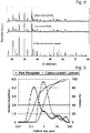
- the XRD patterns of all carbon coated samples match perfectly with the pristine LiFePO 4 and the presence of carbon does not hamper the crystallinity in any way.
- Figure 2 shows the RD pattern of carbon coated LiFePO 4 through lactose compared with the pristine LiFePO 4 .
- the particle size distribution of the carbon coated sample which is obtained after annealing is broader than that of the as synthesised pristine LiFePO 4 .
- a comparison of the particle size distribution of the carbon coated sample prepared by the composition of lactose to the pristine, uncoated LiFePO 4 is shown in Figure 3 .
- the D80 value of the carbon coated sample was found to be less than or equal to 30 ⁇ m, which has roughly grown by a factor of three in comparison to the primary sample.
- the extremely thin amorphous layer of carbon around the carbon coated LiFePO 4 particles can be depicted by high resolution TEM (not shown).
- the average thickness of the layer was found to be around 2 nm.
- the layer appeared to be highly porous which must facilitate easy diffusion of lithium ions into and from the active material. Also visible in good TEM images is the distance between the [301] separation place of the olivine LiFePO 4 which is around 3 ⁇ .
- the carbon coated sample was made by heat treatment in the presence of lactose (15 % by weight) in an inert environment. After drying, the powders were fired at 650 °C for 6 hours (not including the heat up time at a speed of 2.5 °C min -1 ), followed by a milling or deagglomeration process. The amount of carbon was thermogravimetrically determined to be less than 3 % by weight.
- EDOT ethylenedioxythiophene
- SEM Scanning electron microscopy
- TEM Transmission Electron Microscopy
- the material was deposited onto a holey carbon foil supported on a copper grid.
- TEM investigations were performed using a C30ST microscope (Philips; LaB6 cathode, operate at 300 kV, point resolution ⁇ 2 ⁇ ).
- Conductivity was measured using a four point conductivity testing method.
- composition of the three samples analysed are summarized in the Table 2, wherein L1 designates a reference material obtained with pristine, uncoated LiFePO 4 , LC designates a reference material with carbon coated LiFePO 4 , and LP designates a material of the present invention mixture of carbon coated LiFePO 4 and PEDOT nanoparticles:
- PEDOT nanoparticles were dispersed in acetonitrile solution and then mixed 10 % by weight with the pristine LiFePO 4 .
- sacrificial particles can be admixed and - as soon as the "pre-electrode" is dried - removed.
- the cells were assembled in an argon filled glove box using lithium metal foil as the counter electrode.
- the electrolyte used was MERCK Selectipur, LP30, which consists of 1 M solution of LiPF 6 in mixture of ethylene carbonate and dimethyl carbonate 1:1 (w/w).
- Fig. 2 shows the XRD pattern of L1 which consistent to an orthorhombic crystal structure with space group Pnma.
- the patterns correspond perfectly to the theoretical pattern of LiFePO 4 and no impurities were detected.
- the XRD pattern of the carbon coated sample LC matches perfectly with the bare sample L1 and the presence of carbon does not hamper the crystallinity in any way.
- the single crystal size estimated using the width derived from the XRD (020) line is 31.6 nm.
- a SEM image of LC1 illustrates that the grains had a distinct elliptical morphology with an average particle size of 200 nm.
- the morphology of the LC had no significant difference from L1.
- the high solution TEM image of LC depicts the extremely thin amorphous layer of carbon around the LiFePO 4 particles.
- the average thickness of the layer was measured to be around 2 nm.
- the layer appeared to be highly porous which must facilitate easy diffusion of lithium ions inside the active material.
- the interplanar distance was deciphered to be ⁇ 3 ⁇ which closely resembles the [301] plane separation of the olivine.
- the carbon coated sample had conductivity in the range of 10 -4 S/cm which is several magnitudes higher than pristine LiFePO 4 (10 -9 S/cm).
- a SEM picture of the battery composite consisting of LC, graphite and the standard binder (not shown or Fig.4 ) illustrates that microsized graphite which should ideally act as conductive interconnect between the insulating LiFePO 4 particles is completely out of range in comparison to the nanosized active material. It remains as an isolated island in the matrix and hardly benefits the electron percolation network despite significantly contributing to the weight of the electrode composite. This problem was successfully solved in LP.
- the reverse microemulsion directed synthesis of PEDOT lead to the formation of nanosized mesh (not shown or shown in Fig.5 ).
- the porous structure is formed from the agglomeration of individual PEDOT nanostubs.
- the conductive porous nanomesh of PEDOT particles completely wraps the LiFePO 4 particles thus rendering the whole composite to be much more conductive.
- PEDOT particles also act as a binder to bind the electrode ingredients together and with the current collector. This makes the use of any separate binder unnecessary hence alleviating inactive mass from the bulk of the electrode.
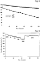
- Fig. 6 shows the initial discharge capacity of all three samples cycled at a specific current of 20 mA ( ⁇ 0.1C). All the samples have an exceptional flat voltage plateau. At this relatively low current both the carbon coated sample (LC) and the polymer composite sample (LP) boast a capacity around 166 mAh g -1 which is very close to the theoretical capacity of 170 mAH g -1 for LiFePO 4 .
- the uncoated sample (L1) has a start capacity of 110 mAh g -1 which is significantly lower than the other two samples. For all three samples the discharge capacity at this current remains stable for a very high number of cycles. This discrepancy in performance clearly illustrates the influence of conductivity on the performance of the electrode.
- Fig. 7a and Fig. 7b compare the performance of LC and LP at a specific current of 135 mAh g -1 ( ⁇ 0.8C).
- the initial discharge capacity of LP is 158.5 mAh g -1 .
- Figure 7a shows the subsequent discharge curves for the 10 th , 50 th and 100 th cycle. The capacities at these cycles are 158 mAh g -1 , 159 mAh g -1 and 141 mAh g -1 , respectively. This represents a drop of around 0.17 mAh g -1 per cycle and implies that 90 % of the initial discharge capacity is retained after 100 cycles.
- the sample LC has a initial discharge capacity of 145 mAh g -1 which is followed by 128 mAh g -1 , 112 mAh g -1 and 97 mAh g -1 for the 10 th , 50 th and 100 th cycle respectively. This represents a drop of around 0.33 mAh g -1 per cycle and only 67 % of the original capacity is retained after 100 cycles. Hence for LP both the start capacity and the capacity retention are significantly better than LC. Both the sample show almost linear decline with the same rate for the next 100 cycles as show in Fig. 8 .
- the final discharge capacity of LP after 200 cycles is 130 mAh g -1 compared to 56 mAh g -1 for LC.
- Fig. 7a show the differential specific capacity plots (DSCP) for both these samples at the corresponding 10 th , 50 th and 100 th discharge cycle.
- the peak of these differential specific capacity plots corresponds to the anodic and cathodic plateau of the lithium intercalation/deintercalation from the active material. Both the anodic and the cathodic peak occur around 3.4 V which is the lithium extraction/insertion potential in LiFePO 4 .
- the main differences between the two plots are the polarization gap between the anodic and the cathodic peak and the intensity of the peaks.
- the separation is around 0.1 V whereas its 0.6 V in LC. This separation indicates the amount of overpotential in the electrode mix which primarily suggests higher electrode resistance in LC.
- the peak intensity of the polymer composite LP is much higher than LC which indicates better Li insertion kinetics than the latter.
- Fig. 9 depicts the discharge potential as a function of number of cycles at various currents. At C/5 the samples exhibits an almost theoretical capacity of 170 mAh g -1 . This value steadily decreases with the increase of current but even at a high current corresponding to 10C a relatively steady discharge capacity of around 130 mAh g -1 is observed. After the current is dropped to its initial value most of the original capacity is retained.
- the performance of the composite of PEDOT and LiFePO 4 was significantly better compared to the bare and carbon coated LiFePO 4 .
- the conductive polymer containing composite outperforms the other two samples while having only 50 % of their total additive content with respect to the weight of the electrode.
Claims (20)
- Zwischennanoverbundstoff für positive oder negative Elektroden von aufladbaren Lithiumbatterien, wobei der Nanoverbundstoff ein offenes poröses Material ist, das homogen verteiltes nanopartikuläres elektronisch aktives Material und nanopartikuläres elektronisch leitendes Bindematerial umfasst, wobei die Nanoteilchen des elektronisch aktiven Materials mit einer leitenden Schicht beschichtet sind und die Nanoteilchen des elektronischen Bindematerials die Form von Nano-Stümpfe haben oder ungefähr kugelförmig sind, wobei die mittlere Teilchengröße der Nanoteilchen des elektronisch aktiven Materials und die mittlere Teilchengröße des elektronisch leitenden Bindematerials
beide um nicht mehr als +100 %/-50 % verschieden sind und/oder
beide in dem Bereich von 5 bis 500 nm liegen,
dadurch gekennzeichnet, dass der Zwischennanoverbundstoff ferner Opfernanoteilchen umfasst, die mit dem nanopartikulären elektronisch aktiven Material homogen verteilt sind und wobei die Teilchengröße des nanopartikulären elektronisch leitenden Bindematerials und die Teilchengröße der Opfernanoteilchen in dem Bereich von 200 bis 500 nm liegen. - Zwischennanoverbundstoff nach Anspruch 1, wobei die Elektrode eine positive Elektrode ist und das elektronisch aktive Material aus Oxiden, Nitriden, Karbiden, Boraten, Phosphaten, Sulfiden, Halogeniden der Übergangsmetalle und Hauptgruppenmetalle und Mischungen davon ausgewählt ist.
- Zwischennanoverbundstoff nach Anspruch 2, wobei das elektronisch aktive Material LiFePO4 ist.
- Zwischennanoverbundstoff nach Anspruch 1, wobei die Elektrode eine negative Elektrode ist und wobei das elektronisch aktive Anodenmaterial aus Silizium, LixSiSnn, LixAlSin, und Nitriden ausgewählt ist.
- Zwischennanoverbundstoff nach einem der vorhergehenden Ansprüche, wobei die leitende Schicht eine Kohlenstoff- oder Graphit-/Graphenschicht ist.
- Zwischennanoverbundstoff nach einem der vorhergehenden Ansprüche, wobei das elektronisch leitende Bindematerial ein Polymer ist, das aus Polyazetylenen, Polyanilinen, Polypyrrol und Polythiophenen ausgewählt ist.
- Zwischennanoverbundstoff nach einem der vorhergehenden Ansprüche, wobei das Bindemittel Poly(3, 4-ethylendioxythiophen) (PEDOT) ist.
- Zwischennanoverbundstoff nach einem der vorhergehenden Ansprüche, wobei die mittlere Teilchengröße der Nanoteilchen des elektronisch leitenden Bindematerials und der Nanoteilchen des elektronisch aktiven Materials in dem Bereich von 5 bis 400 nm liegen.
- Zwischennanoverbundstoff nach Anspruch 8, wobei die mittlere Teilchengröße der Nanoteilchen des elektronisch leitenden Bindematerials und der Nanoteilchen des elektronisch aktiven Materials in dem Bereich von 20 bis 300 nm liegen.
- Zwischennanoverbundstoffelektrodenmaterial nach einem der vorhergehenden Ansprüche, das mindestens ein nanopartikuläres elektronisch leitendes Füllmaterial in einer Menge von 2 bis 10 % bezogen auf das Gewicht des von Opferteilchen freien Nanoverbundstoffmaterials umfasst.
- Zwischennanoverbundstoffelektrodenmaterial nach einem der vorhergehenden Ansprüche, das leitende Nanofasern umfasst.
- Zwischennanoverbundstoffelektrodenmaterial nach einem der vorhergehenden Ansprüche, wobei das elektronisch leitende Bindematerial in einer Menge von 4 bis 10 % bezogen auf das Gewicht des von Opferteilchen freien Nanoverbundstoffmaterials vorhanden ist.
- Zwischennanoverbundstoffmaterial nach einem der vorhergehenden Ansprüche, wobei die Teilchengröße der Opferteilchen in dem Bereich von 300 bis 500 nm liegt.
- Zwischennanoverbundstoff nach einem der vorhergehenden Ansprüche, wobei die Opfernanoteilchen aus Polyethylenteilchen, Polyethylenglycolteilchen, Polyvinylacetalteilchen, Polystyrenteilchen und Mischungen davon ausgewählt sind.
- Zwischennanoverbundstoff nach einem der vorhergehenden Ansprüche, wobei die Opferteilchen in Mengen von 0,5 % bis 60 % vorhanden sind.
- Zwischennanoverbundstoff nach Anspruch 15, wobei die Opferteilchen in Mengen von 0,5 bis 10 % vorhanden sind.
- Zwischennanoverbundstoff nach Anspruch 15, wobei die Opferteilchen in Mengen von 40 bis 60% vorhanden sind.
- Elektrodenmaterial für positive oder negative Elektroden von aufladbaren Lithiumbatterien, wobei das Elektrodenmaterial ein Nanoverbundstoff ist, wobei der Nanoverbundstoff ein offenes poröses Material ist, das homogen verteiltes nanopartikuläres elektronisch aktives Material und nanopartikuläres elektronisch leitendes Bindematerial umfasst, wobei die Nanoteilchen des elektronisch leitenden Bindemittels die Form von Nano-Stümpfen aufweisen oder ungefähr kugelförmig sind, und die Nanoteilchen des elektronisch aktiven Materials mit einer leitenden Schicht beschichtet sind, wobei die mittlere Teilchengröße der Nanoteilchen des elektronisch aktiven Materials und die mittlere Teilchengröße des nanopartikulären elektronisch leitenden Bindematerials
beide um nicht mehr als +100 %/-50 % verschieden sind und/oder
beide in dem Bereich von 5 bis 500 nm liegen,
wobei das nanopartikuläre Elektrodenmaterial Poren in dem Bereich von 200 bis 500 nm umfasst. - Verfahren zum Herstellen eines Nanoverbundstoffelektrodenmaterials aus einem Zwischennanoverbundstoff nach einem der Ansprüche 1 bis 17, das die Schritte umfasst, das nanopartikuläre elektronisch leitende Bindemittel und das nanopartikuläre elektronisch aktive Material innig zu mischen und die Opferteilchen und die Mischung einem Druck und Wärme auszusetzen und die Opferteilchen zu entfernen.
- Verfahren nach Anspruch 19, wobei die Opfernanoteilchen durch Wärmebehandlung oder chemische Reaktion entfernt werden, nachdem die Elektrode gebildet wurde oder während die Elektrode gebildet wird.
Priority Applications (6)
| Application Number | Priority Date | Filing Date | Title |
|---|---|---|---|
| EP09157135.6A EP2237346B1 (de) | 2009-04-01 | 2009-04-01 | Elektrisch leitfähiges Nanoverbundmaterial mit Opfer-Nanopartikeln sowie daraus hergestellte offen poröse Nanoverbundstoffe |
| US12/721,669 US8507135B2 (en) | 2009-04-01 | 2010-03-11 | Electrically conductive nanocomposite material comprising sacrificial nanoparticles and open porous nanocomposites produced thereof |
| TW099107290A TWI458165B (zh) | 2009-04-01 | 2010-03-12 | 包含犠牲性奈米粒子及其所產生之開孔式奈米複合物之導電性奈米複合物材料 |
| JP2010056719A JP5650418B2 (ja) | 2009-03-12 | 2010-03-12 | 犠牲ナノ粒子を含む電気伝導性ナノ複合材料およびそれから生成される開放多孔質ナノ複合材 |
| CN201010190574.1A CN102142536B (zh) | 2009-04-01 | 2010-03-12 | 导电纳米复合材料及由其制成的开口多孔纳米复合物 |
| KR1020100022498A KR101316413B1 (ko) | 2009-03-12 | 2010-03-12 | 희생 나노입자를 포함하는 전기 전도성 나노복합체 물질 및 이에 의해 생산된 개방 다공성 나노복합체 |
Applications Claiming Priority (1)
| Application Number | Priority Date | Filing Date | Title |
|---|---|---|---|
| EP09157135.6A EP2237346B1 (de) | 2009-04-01 | 2009-04-01 | Elektrisch leitfähiges Nanoverbundmaterial mit Opfer-Nanopartikeln sowie daraus hergestellte offen poröse Nanoverbundstoffe |
Publications (2)
| Publication Number | Publication Date |
|---|---|
| EP2237346A1 EP2237346A1 (de) | 2010-10-06 |
| EP2237346B1 true EP2237346B1 (de) | 2017-08-09 |
Family
ID=41000015
Family Applications (1)
| Application Number | Title | Priority Date | Filing Date |
|---|---|---|---|
| EP09157135.6A Active EP2237346B1 (de) | 2009-03-12 | 2009-04-01 | Elektrisch leitfähiges Nanoverbundmaterial mit Opfer-Nanopartikeln sowie daraus hergestellte offen poröse Nanoverbundstoffe |
Country Status (4)
| Country | Link |
|---|---|
| US (1) | US8507135B2 (de) |
| EP (1) | EP2237346B1 (de) |
| CN (1) | CN102142536B (de) |
| TW (1) | TWI458165B (de) |
Families Citing this family (59)
| Publication number | Priority date | Publication date | Assignee | Title |
|---|---|---|---|---|
| EP2237346B1 (de) * | 2009-04-01 | 2017-08-09 | The Swatch Group Research and Development Ltd. | Elektrisch leitfähiges Nanoverbundmaterial mit Opfer-Nanopartikeln sowie daraus hergestellte offen poröse Nanoverbundstoffe |
| EP2228855B1 (de) | 2009-03-12 | 2014-02-26 | Belenos Clean Power Holding AG | Offen poröses elektrisch leitfähiges Nanoverbundmaterial |
| WO2012023464A1 (en) | 2010-08-19 | 2012-02-23 | Semiconductor Energy Laboratory Co., Ltd. | Electrical appliance |
| US8652386B2 (en) | 2010-09-16 | 2014-02-18 | Georgia Tech Research Corporation | Alignment of carbon nanotubes comprising magnetically sensitive metal oxides in nanofluids |
| US20120088151A1 (en) * | 2010-10-08 | 2012-04-12 | Semiconductor Energy Laboratory Co., Ltd. | Positive-electrode active material and power storage device |
| US9490474B2 (en) * | 2010-10-08 | 2016-11-08 | Semiconductor Energy Laboratory Co., Ltd. | Method for manufacturing positive electrode active material for energy storage device and energy storage device |
| US8980126B2 (en) | 2010-10-08 | 2015-03-17 | Semiconductor Energy Laboratory Co., Ltd. | Electrode material and method for manufacturing power storage device |
| EP2698851B1 (de) * | 2011-04-13 | 2018-12-12 | Sei Corporation | Elektrodenmaterial für eine lithiumsekundärbatterie und lithiumsekundärbatterie |
| TWI582041B (zh) | 2011-06-03 | 2017-05-11 | 半導體能源研究所股份有限公司 | 單層和多層石墨烯,彼之製法,含彼之物件,以及含彼之電器裝置 |
| KR102489415B1 (ko) | 2011-06-03 | 2023-01-18 | 가부시키가이샤 한도오따이 에네루기 켄큐쇼 | 정극, 리튬 이온 이차 전지, 이동체, 차량, 시스템, 및 전자 기기 |
| US11296322B2 (en) | 2011-06-03 | 2022-04-05 | Semiconductor Energy Laboratory Co., Ltd. | Single-layer and multilayer graphene, method of manufacturing the same, object including the same, and electric device including the same |
| US9218916B2 (en) | 2011-06-24 | 2015-12-22 | Semiconductor Energy Laboratory Co., Ltd. | Graphene, power storage device, and electric device |
| JP6025284B2 (ja) | 2011-08-19 | 2016-11-16 | 株式会社半導体エネルギー研究所 | 蓄電装置用の電極及び蓄電装置 |
| WO2013027561A1 (en) | 2011-08-19 | 2013-02-28 | Semiconductor Energy Laboratory Co., Ltd. | Method for manufacturing graphene-coated object, negative electrode of secondary battery including graphene-coated object, and secondary battery including the negative electrode |
| KR20130024769A (ko) | 2011-08-30 | 2013-03-08 | 가부시키가이샤 한도오따이 에네루기 켄큐쇼 | 축전 장치 |
| US9249524B2 (en) | 2011-08-31 | 2016-02-02 | Semiconductor Energy Laboratory Co., Ltd. | Manufacturing method of composite oxide and manufacturing method of power storage device |
| JP6000017B2 (ja) | 2011-08-31 | 2016-09-28 | 株式会社半導体エネルギー研究所 | 蓄電装置及びその作製方法 |
| JP6029898B2 (ja) | 2011-09-09 | 2016-11-24 | 株式会社半導体エネルギー研究所 | リチウム二次電池用正極の作製方法 |
| CA2752844A1 (en) * | 2011-09-19 | 2013-03-19 | Hydro-Quebec | Method for preparing a particulate of si or siox-based anode material, and material thus obtained |
| US9401247B2 (en) | 2011-09-21 | 2016-07-26 | Semiconductor Energy Laboratory Co., Ltd. | Negative electrode for power storage device and power storage device |
| JP6218349B2 (ja) | 2011-09-30 | 2017-10-25 | 株式会社半導体エネルギー研究所 | 蓄電装置 |
| CN103858259B (zh) | 2011-09-30 | 2018-03-06 | 株式会社半导体能源研究所 | 石墨烯及蓄电装置、及它们的制造方法 |
| CA2754372A1 (en) | 2011-10-04 | 2013-04-04 | Hydro-Quebec | Positive-electrode material for lithium-ion secondary battery and method of producing same |
| CN103035922B (zh) | 2011-10-07 | 2019-02-19 | 株式会社半导体能源研究所 | 蓄电装置 |
| US9487880B2 (en) | 2011-11-25 | 2016-11-08 | Semiconductor Energy Laboratory Co., Ltd. | Flexible substrate processing apparatus |
| JP6016597B2 (ja) | 2011-12-16 | 2016-10-26 | 株式会社半導体エネルギー研究所 | リチウムイオン二次電池用正極の製造方法 |
| JP6009343B2 (ja) | 2011-12-26 | 2016-10-19 | 株式会社半導体エネルギー研究所 | 二次電池用正極および二次電池用正極の作製方法 |
| US9680272B2 (en) | 2012-02-17 | 2017-06-13 | Semiconductor Energy Laboratory Co., Ltd. | Method for forming negative electrode and method for manufacturing lithium secondary battery |
| JP5719859B2 (ja) | 2012-02-29 | 2015-05-20 | 株式会社半導体エネルギー研究所 | 蓄電装置 |
| JP6077347B2 (ja) | 2012-04-10 | 2017-02-08 | 株式会社半導体エネルギー研究所 | 非水系二次電池用正極の製造方法 |
| US9225003B2 (en) | 2012-06-15 | 2015-12-29 | Semiconductor Energy Laboratory Co., Ltd. | Method for manufacturing storage battery electrode, storage battery electrode, storage battery, and electronic device |
| US9954220B2 (en) | 2012-06-15 | 2018-04-24 | Max-Planck-Gesellschaft Zur Forderung Der Wissenschaften E.V. | Method of manufacture of an electrode material and an electrode material |
| JP6207923B2 (ja) | 2012-08-27 | 2017-10-04 | 株式会社半導体エネルギー研究所 | 二次電池用正極の製造方法 |
| JP6159228B2 (ja) | 2012-11-07 | 2017-07-05 | 株式会社半導体エネルギー研究所 | 非水系二次電池用正極の製造方法 |
| US9673454B2 (en) | 2013-02-18 | 2017-06-06 | Semiconductor Energy Laboratory Co., Ltd. | Sodium-ion secondary battery |
| US9490472B2 (en) | 2013-03-28 | 2016-11-08 | Semiconductor Energy Laboratory Co., Ltd. | Method for manufacturing electrode for storage battery |
| KR20140121953A (ko) | 2013-04-08 | 2014-10-17 | 주식회사 엘지화학 | 리튬 이차전지용 음극, 그 제조방법 및 이를 포함하는 리튬 이차 전지 |
| KR101580030B1 (ko) | 2013-07-09 | 2015-12-23 | 주식회사 엘지화학 | 탄소 코팅 리튬 인산철 나노분말의 제조방법 |
| US20150044560A1 (en) | 2013-08-09 | 2015-02-12 | Semiconductor Energy Laboratory Co., Ltd. | Electrode for lithium-ion secondary battery and manufacturing method thereof, and lithium-ion secondary battery |
| US9312046B2 (en) | 2014-02-12 | 2016-04-12 | South Dakota Board Of Regents | Composite materials with magnetically aligned carbon nanoparticles having enhanced electrical properties and methods of preparation |
| WO2015157249A1 (en) * | 2014-04-07 | 2015-10-15 | Johnson Ip Holding, Llc | Lithium based anode with nano-composite structure and method of manufacturing such |
| WO2015164848A1 (en) | 2014-04-25 | 2015-10-29 | South Dakota Board Of Regents | High capacity electrodes |
| US11639425B2 (en) * | 2014-05-12 | 2023-05-02 | The Trustees Of The University Of Pennsylvania | Nanocomposite films and methods for producing the same |
| JP6745587B2 (ja) | 2014-05-29 | 2020-08-26 | 株式会社半導体エネルギー研究所 | 電極の製造方法 |
| DE102014214899A1 (de) * | 2014-07-30 | 2016-02-04 | Bayerische Motoren Werke Aktiengesellschaft | Kompositelektrode für eine elektrochemische Zelle und elektrochemische Zelle |
| WO2016033211A2 (en) | 2014-08-27 | 2016-03-03 | 3M Innovative Properties Company | Electrical multilayer lamination transfer films |
| CN104638242A (zh) * | 2015-02-06 | 2015-05-20 | 重庆特瑞电池材料股份有限公司 | 原位聚合包覆合成锂离子电池正极材料磷酸铁锂的方法 |
| WO2017083825A1 (en) * | 2015-11-13 | 2017-05-18 | David Mitlin | Activated carbons from dairy products |
| CN106571244A (zh) * | 2016-11-02 | 2017-04-19 | 南京工业大学 | 二维过渡族金属碳(氮)化合物与二维过渡族金属硫化物纳米复合粉体及制备和应用 |
| CN106784724B (zh) * | 2017-01-12 | 2020-08-07 | 吉林大学 | 一种LiFePO4@C/rGO多级复合微球的溶剂热辅助制备方法 |
| JP6332540B1 (ja) * | 2017-09-29 | 2018-05-30 | 住友大阪セメント株式会社 | リチウムイオン二次電池用正極材料、リチウムイオン二次電池用正極、リチウムイオン二次電池 |
| CN107768627A (zh) * | 2017-10-03 | 2018-03-06 | 长沙仲善新能源科技有限公司 | 一种高温稳定性镍钴锰酸锂复合电极及其制备方法与应用 |
| US10985407B2 (en) | 2017-11-21 | 2021-04-20 | Samsung Electronics Co., Ltd. | All-solid-state secondary battery including anode active material alloyable with lithium and method of charging the same |
| US10468674B2 (en) | 2018-01-09 | 2019-11-05 | South Dakota Board Of Regents | Layered high capacity electrodes |
| US11437643B2 (en) | 2018-02-20 | 2022-09-06 | Samsung Electronics Co., Ltd. | All-solid-state secondary battery |
| WO2020154235A1 (en) * | 2019-01-22 | 2020-07-30 | Xg Sciences, Inc. | Silicon/graphene composite anode material and method to manufacture the same |
| US11824155B2 (en) | 2019-05-21 | 2023-11-21 | Samsung Electronics Co., Ltd. | All-solid lithium secondary battery and method of charging the same |
| KR20210048291A (ko) | 2019-10-23 | 2021-05-03 | 삼성전자주식회사 | 금속공기전지용 양극, 그 제조방법 및 이를 포함하는 금속공기전지 |
| CN112394568B (zh) * | 2020-12-15 | 2022-09-13 | 厦门天马微电子有限公司 | 显示面板及显示装置 |
Citations (3)
| Publication number | Priority date | Publication date | Assignee | Title |
|---|---|---|---|---|
| EP1244168A1 (de) * | 2001-03-20 | 2002-09-25 | Francois Sugnaux | Mesoporöse Netzwerk-Elektrode für elektrochemische Zelle |
| US20060151318A1 (en) * | 2005-01-11 | 2006-07-13 | Jin-Hwan Park | Electrode for electrochemical cell, method of manufacturing the same, and electrochemical cell includng the electrode |
| EP2228855A1 (de) * | 2009-03-12 | 2010-09-15 | Belenos Clean Power Holding AG | Offen poröses elektrisch leitfähiges Nanoverbundmaterial |
Family Cites Families (39)
| Publication number | Priority date | Publication date | Assignee | Title |
|---|---|---|---|---|
| US2007105A (en) * | 1933-07-18 | 1935-07-02 | Firm Bulova Watch Company Inc | Self-winding wrist watch |
| DE3890245C2 (de) | 1987-04-15 | 1992-12-10 | Ricoh Co., Ltd., Tokio/Tokyo, Jp | |
| JPH0817094B2 (ja) | 1989-11-24 | 1996-02-21 | セントラル硝子株式会社 | 電極材料およびその製造法 |
| US5418090A (en) | 1993-02-17 | 1995-05-23 | Valence Technology, Inc. | Electrodes for rechargeable lithium batteries |
| DE69711262T2 (de) | 1996-05-31 | 2002-12-12 | Matsushita Electric Ind Co Ltd | Akkumulator mit nichtwässrigem Elektrolyt |
| JP4172443B2 (ja) | 1996-07-19 | 2008-10-29 | ソニー株式会社 | 非水電解液二次電池用負極材料及び非水電解液二次電池 |
| JP3526707B2 (ja) | 1996-11-27 | 2004-05-17 | 株式会社トクヤマ | 非水電解液二次電池用負極活物質および非水電解液二次電池 |
| JP4453111B2 (ja) | 1997-10-27 | 2010-04-21 | 三菱化学株式会社 | 負極材料とその製造方法、負極活物質、および非水系二次電池 |
| JP4078698B2 (ja) | 1997-12-03 | 2008-04-23 | 宇部興産株式会社 | 非水二次電池用負極材料とその製造方法および電池 |
| JP4547748B2 (ja) * | 1999-10-29 | 2010-09-22 | パナソニック株式会社 | 非水電解質電池 |
| US6998069B1 (en) | 1999-12-03 | 2006-02-14 | Ferro Gmbh | Electrode material for positive electrodes of rechargeable lithium batteries |
| JP4106644B2 (ja) | 2000-04-04 | 2008-06-25 | ソニー株式会社 | 電池およびその製造方法 |
| US7387851B2 (en) * | 2001-07-27 | 2008-06-17 | A123 Systems, Inc. | Self-organizing battery structure with electrode particles that exert a repelling force on the opposite electrode |
| CA2327370A1 (fr) * | 2000-12-05 | 2002-06-05 | Hydro-Quebec | Nouvelle methode de fabrication de li4ti5o12 pur a partir du compose ternaire tix-liy-carbone: effet du carbone sur la synthese et la conductivite de l'electrode |
| EP1244114A1 (de) | 2001-03-20 | 2002-09-25 | ILFORD Imaging Switzerland GmbH | Elektrisch aktive Filme |
| WO2003012908A2 (en) * | 2001-07-27 | 2003-02-13 | Massachusetts Institute Of Technology | Battery structures, self-organizing structures and related methods |
| EP1484809A4 (de) * | 2002-02-07 | 2008-08-13 | Noboru Oyama | Redoxaktive reversible elektrode und neuartige zelle damit |
| JP2004022507A (ja) * | 2002-06-20 | 2004-01-22 | Sony Corp | 電極およびそれを用いた電池 |
| JP3586270B2 (ja) | 2002-08-15 | 2004-11-10 | 株式会社東芝 | 正極活物質及び非水電解質電池 |
| US7531267B2 (en) * | 2003-06-02 | 2009-05-12 | Kh Chemicals Co., Ltd. | Process for preparing carbon nanotube electrode comprising sulfur or metal nanoparticles as a binder |
| CA2432397A1 (fr) * | 2003-06-25 | 2004-12-25 | Hydro-Quebec | Procede de preparation d'electrode a partir d'un silicium poreux, electrode ainsi obtenue et systeme electrochimique contenant au moins une telle electrode |
| KR100601090B1 (ko) * | 2003-10-14 | 2006-07-14 | 주식회사 엘지화학 | 다공성 템플레이트를 이용하여 제조된 고표면적 전극시스템 및 이를 이용한 전기 소자 |
| DE10353266B4 (de) | 2003-11-14 | 2013-02-21 | Süd-Chemie Ip Gmbh & Co. Kg | Lithiumeisenphosphat, Verfahren zu seiner Herstellung und seine Verwendung als Elektrodenmaterial |
| KR100537745B1 (ko) | 2004-06-21 | 2005-12-19 | 한국전기연구원 | 리튬이차전지용 음극 활물질 및 그 제조방법 |
| US7927742B2 (en) * | 2004-10-29 | 2011-04-19 | Medtronic, Inc. | Negative-limited lithium-ion battery |
| DE102004053479A1 (de) | 2004-11-05 | 2006-05-11 | Dilo Trading Ag | Hochleistungsbatterien mit Titanaten als negativem und Eisenphosphat als positivem Elektrodenmaterial und Verfahren zur Herstellung der Hochleistungsbatterien |
| US7615314B2 (en) * | 2004-12-10 | 2009-11-10 | Canon Kabushiki Kaisha | Electrode structure for lithium secondary battery and secondary battery having such electrode structure |
| US20090095942A1 (en) * | 2005-01-26 | 2009-04-16 | Shuichiro Yamaguchi | Positive Electrode Material for Lithium Secondary Battery |
| FR2885734B1 (fr) | 2005-05-13 | 2013-07-05 | Accumulateurs Fixes | Materiau nanocomposite pour anode d'accumulateur au lithium |
| US7968231B2 (en) | 2005-12-23 | 2011-06-28 | U Chicago Argonne, Llc | Electrode materials and lithium battery systems |
| JP5142515B2 (ja) | 2006-12-19 | 2013-02-13 | 三洋電機株式会社 | 非水電解質二次電池 |
| CN101606253A (zh) | 2007-02-07 | 2009-12-16 | 威伦斯技术公司 | 用于二次电化学电池的基于氧氮化物的电极活性材料 |
| US8039152B2 (en) | 2007-04-03 | 2011-10-18 | Toyota Motor Engineering & Manufacturing North America, Inc. | Tin in an active support matrix |
| US8936874B2 (en) | 2008-06-04 | 2015-01-20 | Nanotek Instruments, Inc. | Conductive nanocomposite-based electrodes for lithium batteries |
| JP5684462B2 (ja) | 2008-12-22 | 2015-03-11 | 昭和電工パッケージング株式会社 | 正極タブリード及び電池 |
| US8241793B2 (en) * | 2009-01-02 | 2012-08-14 | Nanotek Instruments, Inc. | Secondary lithium ion battery containing a prelithiated anode |
| US9093693B2 (en) | 2009-01-13 | 2015-07-28 | Samsung Electronics Co., Ltd. | Process for producing nano graphene reinforced composite particles for lithium battery electrodes |
| EP2237346B1 (de) * | 2009-04-01 | 2017-08-09 | The Swatch Group Research and Development Ltd. | Elektrisch leitfähiges Nanoverbundmaterial mit Opfer-Nanopartikeln sowie daraus hergestellte offen poröse Nanoverbundstoffe |
| US8624105B2 (en) | 2009-05-01 | 2014-01-07 | Synkera Technologies, Inc. | Energy conversion device with support member having pore channels |
-
2009
- 2009-04-01 EP EP09157135.6A patent/EP2237346B1/de active Active
-
2010
- 2010-03-11 US US12/721,669 patent/US8507135B2/en active Active
- 2010-03-12 CN CN201010190574.1A patent/CN102142536B/zh active Active
- 2010-03-12 TW TW099107290A patent/TWI458165B/zh active
Patent Citations (3)
| Publication number | Priority date | Publication date | Assignee | Title |
|---|---|---|---|---|
| EP1244168A1 (de) * | 2001-03-20 | 2002-09-25 | Francois Sugnaux | Mesoporöse Netzwerk-Elektrode für elektrochemische Zelle |
| US20060151318A1 (en) * | 2005-01-11 | 2006-07-13 | Jin-Hwan Park | Electrode for electrochemical cell, method of manufacturing the same, and electrochemical cell includng the electrode |
| EP2228855A1 (de) * | 2009-03-12 | 2010-09-15 | Belenos Clean Power Holding AG | Offen poröses elektrisch leitfähiges Nanoverbundmaterial |
Non-Patent Citations (1)
| Title |
|---|
| NOVAK ET AL: "Graphite electrodes with tailored porosity for rechargeable ion-transfer batteries", JOURNAL OF POWER SOURCES, ELSEVIER SA, CH, vol. 68, no. 2, 1 October 1997 (1997-10-01), pages 267 - 270, XP005496914, ISSN: 0378-7753, DOI: 10.1016/S0378-7753(96)02561-X * |
Also Published As
| Publication number | Publication date |
|---|---|
| CN102142536B (zh) | 2014-12-10 |
| EP2237346A1 (de) | 2010-10-06 |
| TWI458165B (zh) | 2014-10-21 |
| TW201101563A (en) | 2011-01-01 |
| US20100308277A1 (en) | 2010-12-09 |
| CN102142536A (zh) | 2011-08-03 |
| US8507135B2 (en) | 2013-08-13 |
Similar Documents
| Publication | Publication Date | Title |
|---|---|---|
| EP2237346B1 (de) | Elektrisch leitfähiges Nanoverbundmaterial mit Opfer-Nanopartikeln sowie daraus hergestellte offen poröse Nanoverbundstoffe | |
| EP2228855B1 (de) | Offen poröses elektrisch leitfähiges Nanoverbundmaterial | |
| KR101316413B1 (ko) | 희생 나노입자를 포함하는 전기 전도성 나노복합체 물질 및 이에 의해 생산된 개방 다공성 나노복합체 | |
| Kim et al. | Effect of mechanical activation process parameters on the properties of LiFePO4 cathode material | |
| Kwon et al. | Synthesis and electrochemical properties of olivine LiFePO4 as a cathode material prepared by mechanical alloying | |
| Kim et al. | High-performance FeSb–TiC–C nanocomposite anodes for sodium-ion batteries | |
| JP2023522808A (ja) | 電池用の負極活性材料及びその製造方法、電池負極、電池 | |
| Morales et al. | Cycling-induced stress in lithium ion negative electrodes: LiAl/LiFePO4 and Li4Ti5O12/LiFePO4 cells | |
| Zou et al. | Preparation of carbon-coated LiFe0. 2Mn0. 8PO4 cathode material and its application in a novel battery with Li4Ti5O12 anode | |
| Yang et al. | Cation disordered rock salt phase Li 2 CoTiO 4 as a potential cathode material for Li-ion batteries | |
| Cheng et al. | Surfactant carbonization to synthesize pseudocubic α-Fe2O3/c nanocomposite and its electrochemical performance in lithium-ion batteries | |
| US20140356705A1 (en) | ENCAPSULATED Li2S NANOPARTICLES FOR Li/S BATTERIES WITH ULTRAHIGH ENERGY DENSITIES AND LONG CYCLE LIFE | |
| KR102229454B1 (ko) | 수산화철(FeOOH)의 제조방법 및 수산화철을 포함하는 리튬-황 전지용 양극 | |
| Zhu et al. | Multifunctional vanadium nitride@ N-doped carbon composites for kinetically enhanced lithium–sulfur batteries | |
| Fang et al. | Sn–Ca amorphous alloy as anode for lithium ion battery | |
| Sun et al. | Nano-MgO/AB decorated separator to suppress shuttle effect of lithium–sulfur battery | |
| CN113506861B (zh) | 一种锂离子电池硅基复合负极材料及其制备方法 | |
| Kim et al. | Remarkable improvement in cell safety for Li [Ni0. 5Co0. 2Mn0. 3] O2 coated with LiFePO4 | |
| Kim et al. | Effect of synthetic conditions on the electrochemical properties of LiMn0. 4Fe0. 6PO4/C synthesized by sol–gel technique | |
| Zeng et al. | Micro-sized FeS2@ FeSO4 core-shell composite for advanced lithium storage | |
| WO2018156355A1 (en) | Core-shell electrochemically active particles with modified microstructure and use for secondary battery electrodes | |
| Bresser et al. | Transforming anatase TiO2 nanorods into ultrafine nanoparticles for advanced electrochemical performance | |
| Yu et al. | Pomegranate-like gallium oxide nanospheres coated with nitrogen-doped carbon as an anode for lithium-ion batteries with an ultra-long cycle life | |
| Wang et al. | Enhanced electrochemical performance of Li3V2 (PO4) 3 structurally converted from LiVOPO4 by graphite nanofiber addition | |
| Zhou et al. | Direct synthesis of carbon sheathed tungsten oxide nanoparticles via self-assembly route for high performance electrochemical charge storage electrode |
Legal Events
| Date | Code | Title | Description |
|---|---|---|---|
| PUAI | Public reference made under article 153(3) epc to a published international application that has entered the european phase |
Free format text: ORIGINAL CODE: 0009012 |
|
| AK | Designated contracting states |
Kind code of ref document: A1 Designated state(s): AT BE BG CH CY CZ DE DK EE ES FI FR GB GR HR HU IE IS IT LI LT LU LV MC MK MT NL NO PL PT RO SE SI SK TR |
|
| 17P | Request for examination filed |
Effective date: 20110406 |
|
| 17Q | First examination report despatched |
Effective date: 20110428 |
|
| REG | Reference to a national code |
Ref country code: DE Ref legal event code: R079 Ref document number: 602009047602 Country of ref document: DE Free format text: PREVIOUS MAIN CLASS: H01M0004020000 Ipc: H01M0004134000 |
|
| GRAP | Despatch of communication of intention to grant a patent |
Free format text: ORIGINAL CODE: EPIDOSNIGR1 |
|
| RIC1 | Information provided on ipc code assigned before grant |
Ipc: H01M 4/136 20100101ALI20170424BHEP Ipc: H01M 4/62 20060101ALI20170424BHEP Ipc: H01M 4/36 20060101ALI20170424BHEP Ipc: H01M 4/134 20100101AFI20170424BHEP Ipc: H01M 4/58 20100101ALI20170424BHEP Ipc: H01M 4/04 20060101ALI20170424BHEP Ipc: H01M 10/052 20100101ALI20170424BHEP |
|
| INTG | Intention to grant announced |
Effective date: 20170524 |
|
| GRAS | Grant fee paid |
Free format text: ORIGINAL CODE: EPIDOSNIGR3 |
|
| GRAA | (expected) grant |
Free format text: ORIGINAL CODE: 0009210 |
|
| AK | Designated contracting states |
Kind code of ref document: B1 Designated state(s): AT BE BG CH CY CZ DE DK EE ES FI FR GB GR HR HU IE IS IT LI LT LU LV MC MK MT NL NO PL PT RO SE SI SK TR |
|
| REG | Reference to a national code |
Ref country code: GB Ref legal event code: FG4D |
|
| REG | Reference to a national code |
Ref country code: CH Ref legal event code: EP Ref country code: AT Ref legal event code: REF Ref document number: 917726 Country of ref document: AT Kind code of ref document: T Effective date: 20170815 |
|
| REG | Reference to a national code |
Ref country code: CH Ref legal event code: NV Representative=s name: ICB INGENIEURS CONSEILS EN BREVETS SA, CH |
|
| REG | Reference to a national code |
Ref country code: IE Ref legal event code: FG4D |
|
| REG | Reference to a national code |
Ref country code: DE Ref legal event code: R096 Ref document number: 602009047602 Country of ref document: DE |
|
| REG | Reference to a national code |
Ref country code: NL Ref legal event code: MP Effective date: 20170809 |
|
| REG | Reference to a national code |
Ref country code: LT Ref legal event code: MG4D |
|
| REG | Reference to a national code |
Ref country code: AT Ref legal event code: MK05 Ref document number: 917726 Country of ref document: AT Kind code of ref document: T Effective date: 20170809 |
|
| PG25 | Lapsed in a contracting state [announced via postgrant information from national office to epo] |
Ref country code: LT Free format text: LAPSE BECAUSE OF FAILURE TO SUBMIT A TRANSLATION OF THE DESCRIPTION OR TO PAY THE FEE WITHIN THE PRESCRIBED TIME-LIMIT Effective date: 20170809 Ref country code: FI Free format text: LAPSE BECAUSE OF FAILURE TO SUBMIT A TRANSLATION OF THE DESCRIPTION OR TO PAY THE FEE WITHIN THE PRESCRIBED TIME-LIMIT Effective date: 20170809 Ref country code: AT Free format text: LAPSE BECAUSE OF FAILURE TO SUBMIT A TRANSLATION OF THE DESCRIPTION OR TO PAY THE FEE WITHIN THE PRESCRIBED TIME-LIMIT Effective date: 20170809 Ref country code: SE Free format text: LAPSE BECAUSE OF FAILURE TO SUBMIT A TRANSLATION OF THE DESCRIPTION OR TO PAY THE FEE WITHIN THE PRESCRIBED TIME-LIMIT Effective date: 20170809 Ref country code: NO Free format text: LAPSE BECAUSE OF FAILURE TO SUBMIT A TRANSLATION OF THE DESCRIPTION OR TO PAY THE FEE WITHIN THE PRESCRIBED TIME-LIMIT Effective date: 20171109 Ref country code: NL Free format text: LAPSE BECAUSE OF FAILURE TO SUBMIT A TRANSLATION OF THE DESCRIPTION OR TO PAY THE FEE WITHIN THE PRESCRIBED TIME-LIMIT Effective date: 20170809 Ref country code: HR Free format text: LAPSE BECAUSE OF FAILURE TO SUBMIT A TRANSLATION OF THE DESCRIPTION OR TO PAY THE FEE WITHIN THE PRESCRIBED TIME-LIMIT Effective date: 20170809 |
|
| PG25 | Lapsed in a contracting state [announced via postgrant information from national office to epo] |
Ref country code: ES Free format text: LAPSE BECAUSE OF FAILURE TO SUBMIT A TRANSLATION OF THE DESCRIPTION OR TO PAY THE FEE WITHIN THE PRESCRIBED TIME-LIMIT Effective date: 20170809 Ref country code: PL Free format text: LAPSE BECAUSE OF FAILURE TO SUBMIT A TRANSLATION OF THE DESCRIPTION OR TO PAY THE FEE WITHIN THE PRESCRIBED TIME-LIMIT Effective date: 20170809 Ref country code: IS Free format text: LAPSE BECAUSE OF FAILURE TO SUBMIT A TRANSLATION OF THE DESCRIPTION OR TO PAY THE FEE WITHIN THE PRESCRIBED TIME-LIMIT Effective date: 20171209 Ref country code: LV Free format text: LAPSE BECAUSE OF FAILURE TO SUBMIT A TRANSLATION OF THE DESCRIPTION OR TO PAY THE FEE WITHIN THE PRESCRIBED TIME-LIMIT Effective date: 20170809 Ref country code: BG Free format text: LAPSE BECAUSE OF FAILURE TO SUBMIT A TRANSLATION OF THE DESCRIPTION OR TO PAY THE FEE WITHIN THE PRESCRIBED TIME-LIMIT Effective date: 20171109 Ref country code: GR Free format text: LAPSE BECAUSE OF FAILURE TO SUBMIT A TRANSLATION OF THE DESCRIPTION OR TO PAY THE FEE WITHIN THE PRESCRIBED TIME-LIMIT Effective date: 20171110 |
|
| REG | Reference to a national code |
Ref country code: FR Ref legal event code: PLFP Year of fee payment: 10 |
|
| PG25 | Lapsed in a contracting state [announced via postgrant information from national office to epo] |
Ref country code: CZ Free format text: LAPSE BECAUSE OF FAILURE TO SUBMIT A TRANSLATION OF THE DESCRIPTION OR TO PAY THE FEE WITHIN THE PRESCRIBED TIME-LIMIT Effective date: 20170809 Ref country code: RO Free format text: LAPSE BECAUSE OF FAILURE TO SUBMIT A TRANSLATION OF THE DESCRIPTION OR TO PAY THE FEE WITHIN THE PRESCRIBED TIME-LIMIT Effective date: 20170809 Ref country code: DK Free format text: LAPSE BECAUSE OF FAILURE TO SUBMIT A TRANSLATION OF THE DESCRIPTION OR TO PAY THE FEE WITHIN THE PRESCRIBED TIME-LIMIT Effective date: 20170809 |
|
| REG | Reference to a national code |
Ref country code: DE Ref legal event code: R097 Ref document number: 602009047602 Country of ref document: DE |
|
| PG25 | Lapsed in a contracting state [announced via postgrant information from national office to epo] |
Ref country code: SK Free format text: LAPSE BECAUSE OF FAILURE TO SUBMIT A TRANSLATION OF THE DESCRIPTION OR TO PAY THE FEE WITHIN THE PRESCRIBED TIME-LIMIT Effective date: 20170809 Ref country code: IT Free format text: LAPSE BECAUSE OF FAILURE TO SUBMIT A TRANSLATION OF THE DESCRIPTION OR TO PAY THE FEE WITHIN THE PRESCRIBED TIME-LIMIT Effective date: 20170809 Ref country code: EE Free format text: LAPSE BECAUSE OF FAILURE TO SUBMIT A TRANSLATION OF THE DESCRIPTION OR TO PAY THE FEE WITHIN THE PRESCRIBED TIME-LIMIT Effective date: 20170809 |
|
| PLBE | No opposition filed within time limit |
Free format text: ORIGINAL CODE: 0009261 |
|
| STAA | Information on the status of an ep patent application or granted ep patent |
Free format text: STATUS: NO OPPOSITION FILED WITHIN TIME LIMIT |
|
| 26N | No opposition filed |
Effective date: 20180511 |
|
| PG25 | Lapsed in a contracting state [announced via postgrant information from national office to epo] |
Ref country code: SI Free format text: LAPSE BECAUSE OF FAILURE TO SUBMIT A TRANSLATION OF THE DESCRIPTION OR TO PAY THE FEE WITHIN THE PRESCRIBED TIME-LIMIT Effective date: 20170809 |
|
| PG25 | Lapsed in a contracting state [announced via postgrant information from national office to epo] |
Ref country code: MC Free format text: LAPSE BECAUSE OF FAILURE TO SUBMIT A TRANSLATION OF THE DESCRIPTION OR TO PAY THE FEE WITHIN THE PRESCRIBED TIME-LIMIT Effective date: 20170809 |
|
| REG | Reference to a national code |
Ref country code: BE Ref legal event code: MM Effective date: 20180430 |
|
| GBPC | Gb: european patent ceased through non-payment of renewal fee |
Effective date: 20180401 |
|
| REG | Reference to a national code |
Ref country code: IE Ref legal event code: MM4A |
|
| PG25 | Lapsed in a contracting state [announced via postgrant information from national office to epo] |
Ref country code: LU Free format text: LAPSE BECAUSE OF NON-PAYMENT OF DUE FEES Effective date: 20180401 |
|
| PG25 | Lapsed in a contracting state [announced via postgrant information from national office to epo] |
Ref country code: GB Free format text: LAPSE BECAUSE OF NON-PAYMENT OF DUE FEES Effective date: 20180401 Ref country code: BE Free format text: LAPSE BECAUSE OF NON-PAYMENT OF DUE FEES Effective date: 20180430 |
|
| PG25 | Lapsed in a contracting state [announced via postgrant information from national office to epo] |
Ref country code: IE Free format text: LAPSE BECAUSE OF NON-PAYMENT OF DUE FEES Effective date: 20180401 |
|
| PG25 | Lapsed in a contracting state [announced via postgrant information from national office to epo] |
Ref country code: MT Free format text: LAPSE BECAUSE OF NON-PAYMENT OF DUE FEES Effective date: 20180401 |
|
| PG25 | Lapsed in a contracting state [announced via postgrant information from national office to epo] |
Ref country code: TR Free format text: LAPSE BECAUSE OF FAILURE TO SUBMIT A TRANSLATION OF THE DESCRIPTION OR TO PAY THE FEE WITHIN THE PRESCRIBED TIME-LIMIT Effective date: 20170809 |
|
| PG25 | Lapsed in a contracting state [announced via postgrant information from national office to epo] |
Ref country code: HU Free format text: LAPSE BECAUSE OF FAILURE TO SUBMIT A TRANSLATION OF THE DESCRIPTION OR TO PAY THE FEE WITHIN THE PRESCRIBED TIME-LIMIT; INVALID AB INITIO Effective date: 20090401 Ref country code: PT Free format text: LAPSE BECAUSE OF FAILURE TO SUBMIT A TRANSLATION OF THE DESCRIPTION OR TO PAY THE FEE WITHIN THE PRESCRIBED TIME-LIMIT Effective date: 20170809 |
|
| PG25 | Lapsed in a contracting state [announced via postgrant information from national office to epo] |
Ref country code: CY Free format text: LAPSE BECAUSE OF FAILURE TO SUBMIT A TRANSLATION OF THE DESCRIPTION OR TO PAY THE FEE WITHIN THE PRESCRIBED TIME-LIMIT Effective date: 20170809 Ref country code: MK Free format text: LAPSE BECAUSE OF NON-PAYMENT OF DUE FEES Effective date: 20170809 |
|
| PGFP | Annual fee paid to national office [announced via postgrant information from national office to epo] |
Ref country code: FR Payment date: 20230321 Year of fee payment: 15 |
|
| P01 | Opt-out of the competence of the unified patent court (upc) registered |
Effective date: 20230615 |
|
| PGFP | Annual fee paid to national office [announced via postgrant information from national office to epo] |
Ref country code: DE Payment date: 20230321 Year of fee payment: 15 Ref country code: CH Payment date: 20230502 Year of fee payment: 15 |