EP2237346A1 - Matériau nano-composite conducteur électriquement comportant des nanoparticules de sacrifice et nano-composites poreuses ouvertes produites ainsi - Google Patents
Matériau nano-composite conducteur électriquement comportant des nanoparticules de sacrifice et nano-composites poreuses ouvertes produites ainsi Download PDFInfo
- Publication number
- EP2237346A1 EP2237346A1 EP09157135A EP09157135A EP2237346A1 EP 2237346 A1 EP2237346 A1 EP 2237346A1 EP 09157135 A EP09157135 A EP 09157135A EP 09157135 A EP09157135 A EP 09157135A EP 2237346 A1 EP2237346 A1 EP 2237346A1
- Authority
- EP
- European Patent Office
- Prior art keywords
- nanocomposite
- nanoparticles
- electrode
- nanoparticulate
- electronically
- Prior art date
- Legal status (The legal status is an assumption and is not a legal conclusion. Google has not performed a legal analysis and makes no representation as to the accuracy of the status listed.)
- Granted
Links
- 239000002105 nanoparticle Substances 0.000 title claims description 42
- 239000002114 nanocomposite Substances 0.000 title claims description 35
- 239000000463 material Substances 0.000 title claims description 32
- OKTJSMMVPCPJKN-UHFFFAOYSA-N Carbon Chemical compound [C] OKTJSMMVPCPJKN-UHFFFAOYSA-N 0.000 claims abstract description 61
- 229910052493 LiFePO4 Inorganic materials 0.000 claims abstract description 50
- 229910052799 carbon Inorganic materials 0.000 claims abstract description 45
- 239000011230 binding agent Substances 0.000 claims abstract description 41
- 229920001609 Poly(3,4-ethylenedioxythiophene) Polymers 0.000 claims abstract description 29
- 239000011149 active material Substances 0.000 claims abstract description 21
- 239000011148 porous material Substances 0.000 claims abstract description 19
- 229910002804 graphite Inorganic materials 0.000 claims abstract description 14
- 239000010439 graphite Substances 0.000 claims abstract description 14
- 229920001940 conductive polymer Polymers 0.000 claims abstract description 7
- 238000004519 manufacturing process Methods 0.000 claims abstract description 5
- 239000002245 particle Substances 0.000 claims description 60
- 239000007772 electrode material Substances 0.000 claims description 22
- 239000000203 mixture Substances 0.000 claims description 19
- 229910052744 lithium Inorganic materials 0.000 claims description 15
- WHXSMMKQMYFTQS-UHFFFAOYSA-N Lithium Chemical compound [Li] WHXSMMKQMYFTQS-UHFFFAOYSA-N 0.000 claims description 14
- -1 poly(3,4-ethylenedioxythiophene) Polymers 0.000 claims description 14
- 239000000945 filler Substances 0.000 claims description 7
- 238000010438 heat treatment Methods 0.000 claims description 7
- 239000002121 nanofiber Substances 0.000 claims description 7
- 239000004793 Polystyrene Substances 0.000 claims description 5
- 150000004767 nitrides Chemical class 0.000 claims description 5
- 229920002223 polystyrene Polymers 0.000 claims description 5
- 239000004698 Polyethylene Substances 0.000 claims description 4
- 229920000573 polyethylene Polymers 0.000 claims description 4
- 229920001223 polyethylene glycol Polymers 0.000 claims description 4
- 238000006243 chemical reaction Methods 0.000 claims description 3
- 238000002156 mixing Methods 0.000 claims description 3
- 235000021317 phosphate Nutrition 0.000 claims description 3
- 150000003013 phosphoric acid derivatives Chemical class 0.000 claims description 3
- 229920001197 polyacetylene Polymers 0.000 claims description 3
- 229910052723 transition metal Inorganic materials 0.000 claims description 3
- 229910018427 LixAlSin Inorganic materials 0.000 claims description 2
- 229910014613 LixSiSnn Inorganic materials 0.000 claims description 2
- 229910019142 PO4 Inorganic materials 0.000 claims description 2
- 229910045601 alloy Inorganic materials 0.000 claims description 2
- 239000000956 alloy Substances 0.000 claims description 2
- 239000010405 anode material Substances 0.000 claims description 2
- 150000001642 boronic acid derivatives Chemical class 0.000 claims description 2
- 239000002322 conducting polymer Substances 0.000 claims description 2
- 229910021389 graphene Inorganic materials 0.000 claims description 2
- 229910052751 metal Inorganic materials 0.000 claims description 2
- 239000002184 metal Substances 0.000 claims description 2
- 150000001247 metal acetylides Chemical class 0.000 claims description 2
- 150000002739 metals Chemical class 0.000 claims description 2
- 229920000767 polyaniline Polymers 0.000 claims description 2
- 229920000123 polythiophene Polymers 0.000 claims description 2
- 229910052710 silicon Inorganic materials 0.000 claims description 2
- 239000010703 silicon Substances 0.000 claims description 2
- 150000003624 transition metals Chemical class 0.000 claims description 2
- 239000002202 Polyethylene glycol Substances 0.000 claims 1
- 239000003575 carbonaceous material Substances 0.000 claims 1
- 150000003568 thioethers Chemical class 0.000 claims 1
- 239000002131 composite material Substances 0.000 abstract description 24
- 229920000642 polymer Polymers 0.000 abstract description 10
- 238000009792 diffusion process Methods 0.000 abstract description 8
- 239000006229 carbon black Substances 0.000 abstract description 6
- 239000003792 electrolyte Substances 0.000 abstract description 6
- 230000006872 improvement Effects 0.000 abstract description 3
- 230000014759 maintenance of location Effects 0.000 abstract description 2
- 230000015572 biosynthetic process Effects 0.000 description 14
- 229910001416 lithium ion Inorganic materials 0.000 description 11
- 238000000034 method Methods 0.000 description 10
- 238000003786 synthesis reaction Methods 0.000 description 10
- XOJVVFBFDXDTEG-UHFFFAOYSA-N Norphytane Natural products CC(C)CCCC(C)CCCC(C)CCCC(C)C XOJVVFBFDXDTEG-UHFFFAOYSA-N 0.000 description 8
- 239000002243 precursor Substances 0.000 description 8
- 230000002441 reversible effect Effects 0.000 description 8
- XLYOFNOQVPJJNP-UHFFFAOYSA-N water Chemical compound O XLYOFNOQVPJJNP-UHFFFAOYSA-N 0.000 description 8
- GUBGYTABKSRVRQ-QKKXKWKRSA-N Lactose Natural products OC[C@H]1O[C@@H](O[C@H]2[C@H](O)[C@@H](O)C(O)O[C@@H]2CO)[C@H](O)[C@@H](O)[C@H]1O GUBGYTABKSRVRQ-QKKXKWKRSA-N 0.000 description 6
- WMFOQBRAJBCJND-UHFFFAOYSA-M Lithium hydroxide Chemical compound [Li+].[OH-] WMFOQBRAJBCJND-UHFFFAOYSA-M 0.000 description 6
- 238000009826 distribution Methods 0.000 description 6
- 239000004530 micro-emulsion Substances 0.000 description 6
- VLKZOEOYAKHREP-UHFFFAOYSA-N n-Hexane Chemical compound CCCCCC VLKZOEOYAKHREP-UHFFFAOYSA-N 0.000 description 6
- CYIDZMCFTVVTJO-UHFFFAOYSA-N pyromellitic acid Chemical compound OC(=O)C1=CC(C(O)=O)=C(C(O)=O)C=C1C(O)=O CYIDZMCFTVVTJO-UHFFFAOYSA-N 0.000 description 6
- 239000000126 substance Substances 0.000 description 6
- 239000011248 coating agent Substances 0.000 description 5
- 238000000576 coating method Methods 0.000 description 5
- 230000001351 cycling effect Effects 0.000 description 5
- 238000003780 insertion Methods 0.000 description 5
- 230000037431 insertion Effects 0.000 description 5
- 239000008101 lactose Substances 0.000 description 5
- 238000004729 solvothermal method Methods 0.000 description 5
- CSCPPACGZOOCGX-UHFFFAOYSA-N Acetone Chemical compound CC(C)=O CSCPPACGZOOCGX-UHFFFAOYSA-N 0.000 description 4
- WEVYAHXRMPXWCK-UHFFFAOYSA-N Acetonitrile Chemical compound CC#N WEVYAHXRMPXWCK-UHFFFAOYSA-N 0.000 description 4
- IJGRMHOSHXDMSA-UHFFFAOYSA-N Atomic nitrogen Chemical compound N#N IJGRMHOSHXDMSA-UHFFFAOYSA-N 0.000 description 4
- HBBGRARXTFLTSG-UHFFFAOYSA-N Lithium ion Chemical compound [Li+] HBBGRARXTFLTSG-UHFFFAOYSA-N 0.000 description 4
- 229920002367 Polyisobutene Polymers 0.000 description 4
- 238000002441 X-ray diffraction Methods 0.000 description 4
- 230000008901 benefit Effects 0.000 description 4
- 150000001875 compounds Chemical class 0.000 description 4
- 230000007423 decrease Effects 0.000 description 4
- 229920002239 polyacrylonitrile Polymers 0.000 description 4
- 230000008569 process Effects 0.000 description 4
- 238000000926 separation method Methods 0.000 description 4
- 239000000654 additive Substances 0.000 description 3
- 239000011231 conductive filler Substances 0.000 description 3
- 238000002848 electrochemical method Methods 0.000 description 3
- 239000004615 ingredient Substances 0.000 description 3
- 150000002500 ions Chemical class 0.000 description 3
- 229910002102 lithium manganese oxide Inorganic materials 0.000 description 3
- 239000000843 powder Substances 0.000 description 3
- 239000002244 precipitate Substances 0.000 description 3
- 238000002360 preparation method Methods 0.000 description 3
- 239000011164 primary particle Substances 0.000 description 3
- 238000000197 pyrolysis Methods 0.000 description 3
- 239000011541 reaction mixture Substances 0.000 description 3
- 230000000717 retained effect Effects 0.000 description 3
- 238000004626 scanning electron microscopy Methods 0.000 description 3
- 150000004763 sulfides Chemical class 0.000 description 3
- 239000000725 suspension Substances 0.000 description 3
- 238000012360 testing method Methods 0.000 description 3
- 229910000314 transition metal oxide Inorganic materials 0.000 description 3
- YMMGRPLNZPTZBS-UHFFFAOYSA-N 2,3-dihydrothieno[2,3-b][1,4]dioxine Chemical compound O1CCOC2=C1C=CS2 YMMGRPLNZPTZBS-UHFFFAOYSA-N 0.000 description 2
- XKRFYHLGVUSROY-UHFFFAOYSA-N Argon Chemical compound [Ar] XKRFYHLGVUSROY-UHFFFAOYSA-N 0.000 description 2
- RYGMFSIKBFXOCR-UHFFFAOYSA-N Copper Chemical compound [Cu] RYGMFSIKBFXOCR-UHFFFAOYSA-N 0.000 description 2
- LFQSCWFLJHTTHZ-UHFFFAOYSA-N Ethanol Chemical compound CCO LFQSCWFLJHTTHZ-UHFFFAOYSA-N 0.000 description 2
- XEEYBQQBJWHFJM-UHFFFAOYSA-N Iron Chemical compound [Fe] XEEYBQQBJWHFJM-UHFFFAOYSA-N 0.000 description 2
- 229910021578 Iron(III) chloride Inorganic materials 0.000 description 2
- LRHPLDYGYMQRHN-UHFFFAOYSA-N N-Butanol Chemical compound CCCCO LRHPLDYGYMQRHN-UHFFFAOYSA-N 0.000 description 2
- GRYLNZFGIOXLOG-UHFFFAOYSA-N Nitric acid Chemical compound O[N+]([O-])=O GRYLNZFGIOXLOG-UHFFFAOYSA-N 0.000 description 2
- 229920005987 OPPANOL® Polymers 0.000 description 2
- 239000002033 PVDF binder Substances 0.000 description 2
- NBIIXXVUZAFLBC-UHFFFAOYSA-N Phosphoric acid Chemical compound OP(O)(O)=O NBIIXXVUZAFLBC-UHFFFAOYSA-N 0.000 description 2
- KAESVJOAVNADME-UHFFFAOYSA-N Pyrrole Chemical compound C=1C=CNC=1 KAESVJOAVNADME-UHFFFAOYSA-N 0.000 description 2
- 238000003917 TEM image Methods 0.000 description 2
- IDSMHEZTLOUMLM-UHFFFAOYSA-N [Li].[O].[Co] Chemical class [Li].[O].[Co] IDSMHEZTLOUMLM-UHFFFAOYSA-N 0.000 description 2
- 238000005054 agglomeration Methods 0.000 description 2
- 230000002776 aggregation Effects 0.000 description 2
- HSFWRNGVRCDJHI-UHFFFAOYSA-N alpha-acetylene Natural products C#C HSFWRNGVRCDJHI-UHFFFAOYSA-N 0.000 description 2
- 238000004458 analytical method Methods 0.000 description 2
- 230000009286 beneficial effect Effects 0.000 description 2
- 150000001722 carbon compounds Chemical class 0.000 description 2
- 238000012512 characterization method Methods 0.000 description 2
- 239000002482 conductive additive Substances 0.000 description 2
- 229910052802 copper Inorganic materials 0.000 description 2
- 239000010949 copper Substances 0.000 description 2
- BWFPGXWASODCHM-UHFFFAOYSA-N copper monosulfide Chemical compound [Cu]=S BWFPGXWASODCHM-UHFFFAOYSA-N 0.000 description 2
- 239000013078 crystal Substances 0.000 description 2
- 230000001419 dependent effect Effects 0.000 description 2
- 238000001035 drying Methods 0.000 description 2
- 239000000839 emulsion Substances 0.000 description 2
- 230000007613 environmental effect Effects 0.000 description 2
- 239000000835 fiber Substances 0.000 description 2
- 239000011888 foil Substances 0.000 description 2
- 239000007789 gas Substances 0.000 description 2
- 238000006713 insertion reaction Methods 0.000 description 2
- RBTARNINKXHZNM-UHFFFAOYSA-K iron trichloride Chemical compound Cl[Fe](Cl)Cl RBTARNINKXHZNM-UHFFFAOYSA-K 0.000 description 2
- BAUYGSIQEAFULO-UHFFFAOYSA-L iron(2+) sulfate (anhydrous) Chemical compound [Fe+2].[O-]S([O-])(=O)=O BAUYGSIQEAFULO-UHFFFAOYSA-L 0.000 description 2
- 229910000359 iron(II) sulfate Inorganic materials 0.000 description 2
- 229910000625 lithium cobalt oxide Inorganic materials 0.000 description 2
- GELKBWJHTRAYNV-UHFFFAOYSA-K lithium iron phosphate Chemical compound [Li+].[Fe+2].[O-]P([O-])([O-])=O GELKBWJHTRAYNV-UHFFFAOYSA-K 0.000 description 2
- QEXMICRJPVUPSN-UHFFFAOYSA-N lithium manganese(2+) oxygen(2-) Chemical class [O-2].[Mn+2].[Li+] QEXMICRJPVUPSN-UHFFFAOYSA-N 0.000 description 2
- INHCSSUBVCNVSK-UHFFFAOYSA-L lithium sulfate Chemical compound [Li+].[Li+].[O-]S([O-])(=O)=O INHCSSUBVCNVSK-UHFFFAOYSA-L 0.000 description 2
- 238000011068 loading method Methods 0.000 description 2
- 229910052976 metal sulfide Inorganic materials 0.000 description 2
- 239000004570 mortar (masonry) Substances 0.000 description 2
- 229910017604 nitric acid Inorganic materials 0.000 description 2
- 229910052757 nitrogen Inorganic materials 0.000 description 2
- 239000010450 olivine Substances 0.000 description 2
- 229910052609 olivine Inorganic materials 0.000 description 2
- 239000007800 oxidant agent Substances 0.000 description 2
- 238000007254 oxidation reaction Methods 0.000 description 2
- 230000001590 oxidative effect Effects 0.000 description 2
- 230000010287 polarization Effects 0.000 description 2
- 238000006116 polymerization reaction Methods 0.000 description 2
- 229920001343 polytetrafluoroethylene Polymers 0.000 description 2
- 239000004810 polytetrafluoroethylene Substances 0.000 description 2
- 229920002981 polyvinylidene fluoride Polymers 0.000 description 2
- 239000000047 product Substances 0.000 description 2
- 239000012925 reference material Substances 0.000 description 2
- 230000004044 response Effects 0.000 description 2
- 229910021332 silicide Inorganic materials 0.000 description 2
- 239000007787 solid Substances 0.000 description 2
- 239000002904 solvent Substances 0.000 description 2
- 229910052596 spinel Inorganic materials 0.000 description 2
- 239000011029 spinel Substances 0.000 description 2
- 239000000758 substrate Substances 0.000 description 2
- 235000000346 sugar Nutrition 0.000 description 2
- 150000008163 sugars Chemical class 0.000 description 2
- 238000004627 transmission electron microscopy Methods 0.000 description 2
- HNSDLXPSAYFUHK-UHFFFAOYSA-N 1,4-bis(2-ethylhexyl) sulfosuccinate Chemical compound CCCCC(CC)COC(=O)CC(S(O)(=O)=O)C(=O)OCC(CC)CCCC HNSDLXPSAYFUHK-UHFFFAOYSA-N 0.000 description 1
- GKWLILHTTGWKLQ-UHFFFAOYSA-N 2,3-dihydrothieno[3,4-b][1,4]dioxine Chemical compound O1CCOC2=CSC=C21 GKWLILHTTGWKLQ-UHFFFAOYSA-N 0.000 description 1
- KMTRUDSVKNLOMY-UHFFFAOYSA-N Ethylene carbonate Chemical compound O=C1OCCO1 KMTRUDSVKNLOMY-UHFFFAOYSA-N 0.000 description 1
- MBMLMWLHJBBADN-UHFFFAOYSA-N Ferrous sulfide Chemical compound [Fe]=S MBMLMWLHJBBADN-UHFFFAOYSA-N 0.000 description 1
- DGAQECJNVWCQMB-PUAWFVPOSA-M Ilexoside XXIX Chemical compound C[C@@H]1CC[C@@]2(CC[C@@]3(C(=CC[C@H]4[C@]3(CC[C@@H]5[C@@]4(CC[C@@H](C5(C)C)OS(=O)(=O)[O-])C)C)[C@@H]2[C@]1(C)O)C)C(=O)O[C@H]6[C@@H]([C@H]([C@@H]([C@H](O6)CO)O)O)O.[Na+] DGAQECJNVWCQMB-PUAWFVPOSA-M 0.000 description 1
- 229910025794 LaB6 Inorganic materials 0.000 description 1
- 229910001290 LiPF6 Inorganic materials 0.000 description 1
- 229910016837 LixHnV3O8 Inorganic materials 0.000 description 1
- 229910015084 LixV3O8 Inorganic materials 0.000 description 1
- 240000007817 Olea europaea Species 0.000 description 1
- ULUAUXLGCMPNKK-UHFFFAOYSA-N Sulfobutanedioic acid Chemical compound OC(=O)CC(C(O)=O)S(O)(=O)=O ULUAUXLGCMPNKK-UHFFFAOYSA-N 0.000 description 1
- 238000005411 Van der Waals force Methods 0.000 description 1
- RLTFLELMPUMVEH-UHFFFAOYSA-N [Li+].[O--].[O--].[O--].[V+5] Chemical class [Li+].[O--].[O--].[O--].[V+5] RLTFLELMPUMVEH-UHFFFAOYSA-N 0.000 description 1
- 230000000996 additive effect Effects 0.000 description 1
- 239000004411 aluminium Substances 0.000 description 1
- 229910052782 aluminium Inorganic materials 0.000 description 1
- XAGFODPZIPBFFR-UHFFFAOYSA-N aluminium Chemical compound [Al] XAGFODPZIPBFFR-UHFFFAOYSA-N 0.000 description 1
- 238000000137 annealing Methods 0.000 description 1
- 229910052786 argon Inorganic materials 0.000 description 1
- 239000012298 atmosphere Substances 0.000 description 1
- QVGXLLKOCUKJST-UHFFFAOYSA-N atomic oxygen Chemical compound [O] QVGXLLKOCUKJST-UHFFFAOYSA-N 0.000 description 1
- 239000002388 carbon-based active material Substances 0.000 description 1
- 239000003795 chemical substances by application Substances 0.000 description 1
- 239000004020 conductor Substances 0.000 description 1
- 239000013256 coordination polymer Substances 0.000 description 1
- ORTQZVOHEJQUHG-UHFFFAOYSA-L copper(II) chloride Chemical compound Cl[Cu]Cl ORTQZVOHEJQUHG-UHFFFAOYSA-L 0.000 description 1
- 238000009831 deintercalation Methods 0.000 description 1
- 230000008021 deposition Effects 0.000 description 1
- 238000013461 design Methods 0.000 description 1
- IEJIGPNLZYLLBP-UHFFFAOYSA-N dimethyl carbonate Chemical compound COC(=O)OC IEJIGPNLZYLLBP-UHFFFAOYSA-N 0.000 description 1
- 230000003467 diminishing effect Effects 0.000 description 1
- 239000012153 distilled water Substances 0.000 description 1
- 238000001493 electron microscopy Methods 0.000 description 1
- 230000002708 enhancing effect Effects 0.000 description 1
- 238000001704 evaporation Methods 0.000 description 1
- 230000008020 evaporation Effects 0.000 description 1
- 238000002474 experimental method Methods 0.000 description 1
- 238000000605 extraction Methods 0.000 description 1
- 238000010304 firing Methods 0.000 description 1
- 229910052732 germanium Inorganic materials 0.000 description 1
- GNPVGFCGXDBREM-UHFFFAOYSA-N germanium atom Chemical compound [Ge] GNPVGFCGXDBREM-UHFFFAOYSA-N 0.000 description 1
- 230000009477 glass transition Effects 0.000 description 1
- 238000002173 high-resolution transmission electron microscopy Methods 0.000 description 1
- 238000000265 homogenisation Methods 0.000 description 1
- 239000012535 impurity Substances 0.000 description 1
- 239000011261 inert gas Substances 0.000 description 1
- 239000011810 insulating material Substances 0.000 description 1
- 239000012212 insulator Substances 0.000 description 1
- 238000009830 intercalation Methods 0.000 description 1
- 230000002687 intercalation Effects 0.000 description 1
- 238000011835 investigation Methods 0.000 description 1
- 229910052742 iron Inorganic materials 0.000 description 1
- WBJZTOZJJYAKHQ-UHFFFAOYSA-K iron(3+) phosphate Chemical compound [Fe+3].[O-]P([O-])([O-])=O WBJZTOZJJYAKHQ-UHFFFAOYSA-K 0.000 description 1
- 229910000399 iron(III) phosphate Inorganic materials 0.000 description 1
- 150000002576 ketones Chemical class 0.000 description 1
- XCAUINMIESBTBL-UHFFFAOYSA-N lead(ii) sulfide Chemical compound [Pb]=S XCAUINMIESBTBL-UHFFFAOYSA-N 0.000 description 1
- 239000007788 liquid Substances 0.000 description 1
- 150000002642 lithium compounds Chemical class 0.000 description 1
- 208000020960 lithium transport Diseases 0.000 description 1
- 229910000686 lithium vanadium oxide Inorganic materials 0.000 description 1
- VLXXBCXTUVRROQ-UHFFFAOYSA-N lithium;oxido-oxo-(oxomanganiooxy)manganese Chemical compound [Li+].[O-][Mn](=O)O[Mn]=O VLXXBCXTUVRROQ-UHFFFAOYSA-N 0.000 description 1
- URIIGZKXFBNRAU-UHFFFAOYSA-N lithium;oxonickel Chemical class [Li].[Ni]=O URIIGZKXFBNRAU-UHFFFAOYSA-N 0.000 description 1
- 239000011159 matrix material Substances 0.000 description 1
- 238000005259 measurement Methods 0.000 description 1
- 229910052603 melanterite Inorganic materials 0.000 description 1
- 229910001463 metal phosphate Inorganic materials 0.000 description 1
- 239000013528 metallic particle Substances 0.000 description 1
- 238000000593 microemulsion method Methods 0.000 description 1
- 238000003801 milling Methods 0.000 description 1
- 239000000178 monomer Substances 0.000 description 1
- 239000002086 nanomaterial Substances 0.000 description 1
- 239000002106 nanomesh Substances 0.000 description 1
- 239000011858 nanopowder Substances 0.000 description 1
- 239000002071 nanotube Substances 0.000 description 1
- 231100000252 nontoxic Toxicity 0.000 description 1
- 230000003000 nontoxic effect Effects 0.000 description 1
- 238000005457 optimization Methods 0.000 description 1
- 239000003960 organic solvent Substances 0.000 description 1
- 230000003647 oxidation Effects 0.000 description 1
- 239000001301 oxygen Substances 0.000 description 1
- 229910052760 oxygen Inorganic materials 0.000 description 1
- 238000005325 percolation Methods 0.000 description 1
- TWHXWYVOWJCXSI-UHFFFAOYSA-N phosphoric acid;hydrate Chemical compound O.OP(O)(O)=O TWHXWYVOWJCXSI-UHFFFAOYSA-N 0.000 description 1
- 239000006187 pill Substances 0.000 description 1
- 229920002037 poly(vinyl butyral) polymer Polymers 0.000 description 1
- 229920000128 polypyrrole Polymers 0.000 description 1
- QQONPFPTGQHPMA-UHFFFAOYSA-N propylene Natural products CC=C QQONPFPTGQHPMA-UHFFFAOYSA-N 0.000 description 1
- 125000004805 propylene group Chemical group [H]C([H])([H])C([H])([*:1])C([H])([H])[*:2] 0.000 description 1
- 230000005855 radiation Effects 0.000 description 1
- 230000009257 reactivity Effects 0.000 description 1
- 238000009877 rendering Methods 0.000 description 1
- 230000005070 ripening Effects 0.000 description 1
- 150000003839 salts Chemical class 0.000 description 1
- 238000001878 scanning electron micrograph Methods 0.000 description 1
- 238000007789 sealing Methods 0.000 description 1
- FVBUAEGBCNSCDD-UHFFFAOYSA-N silicide(4-) Chemical compound [Si-4] FVBUAEGBCNSCDD-UHFFFAOYSA-N 0.000 description 1
- 229910052708 sodium Inorganic materials 0.000 description 1
- 239000011734 sodium Substances 0.000 description 1
- 238000000935 solvent evaporation Methods 0.000 description 1
- 239000007858 starting material Substances 0.000 description 1
- 238000003860 storage Methods 0.000 description 1
- 239000012815 thermoplastic material Substances 0.000 description 1
- 230000000007 visual effect Effects 0.000 description 1
Images


Classifications
-
- H—ELECTRICITY
- H01—ELECTRIC ELEMENTS
- H01M—PROCESSES OR MEANS, e.g. BATTERIES, FOR THE DIRECT CONVERSION OF CHEMICAL ENERGY INTO ELECTRICAL ENERGY
- H01M4/00—Electrodes
- H01M4/02—Electrodes composed of, or comprising, active material
- H01M4/04—Processes of manufacture in general
- H01M4/043—Processes of manufacture in general involving compressing or compaction
-
- H—ELECTRICITY
- H01—ELECTRIC ELEMENTS
- H01M—PROCESSES OR MEANS, e.g. BATTERIES, FOR THE DIRECT CONVERSION OF CHEMICAL ENERGY INTO ELECTRICAL ENERGY
- H01M10/00—Secondary cells; Manufacture thereof
- H01M10/05—Accumulators with non-aqueous electrolyte
- H01M10/052—Li-accumulators
-
- H—ELECTRICITY
- H01—ELECTRIC ELEMENTS
- H01M—PROCESSES OR MEANS, e.g. BATTERIES, FOR THE DIRECT CONVERSION OF CHEMICAL ENERGY INTO ELECTRICAL ENERGY
- H01M4/00—Electrodes
- H01M4/02—Electrodes composed of, or comprising, active material
- H01M4/04—Processes of manufacture in general
- H01M4/0471—Processes of manufacture in general involving thermal treatment, e.g. firing, sintering, backing particulate active material, thermal decomposition, pyrolysis
-
- H—ELECTRICITY
- H01—ELECTRIC ELEMENTS
- H01M—PROCESSES OR MEANS, e.g. BATTERIES, FOR THE DIRECT CONVERSION OF CHEMICAL ENERGY INTO ELECTRICAL ENERGY
- H01M4/00—Electrodes
- H01M4/02—Electrodes composed of, or comprising, active material
- H01M4/04—Processes of manufacture in general
- H01M4/049—Manufacturing of an active layer by chemical means
-
- H—ELECTRICITY
- H01—ELECTRIC ELEMENTS
- H01M—PROCESSES OR MEANS, e.g. BATTERIES, FOR THE DIRECT CONVERSION OF CHEMICAL ENERGY INTO ELECTRICAL ENERGY
- H01M4/00—Electrodes
- H01M4/02—Electrodes composed of, or comprising, active material
- H01M4/13—Electrodes for accumulators with non-aqueous electrolyte, e.g. for lithium-accumulators; Processes of manufacture thereof
- H01M4/134—Electrodes based on metals, Si or alloys
-
- H—ELECTRICITY
- H01—ELECTRIC ELEMENTS
- H01M—PROCESSES OR MEANS, e.g. BATTERIES, FOR THE DIRECT CONVERSION OF CHEMICAL ENERGY INTO ELECTRICAL ENERGY
- H01M4/00—Electrodes
- H01M4/02—Electrodes composed of, or comprising, active material
- H01M4/13—Electrodes for accumulators with non-aqueous electrolyte, e.g. for lithium-accumulators; Processes of manufacture thereof
- H01M4/136—Electrodes based on inorganic compounds other than oxides or hydroxides, e.g. sulfides, selenides, tellurides, halogenides or LiCoFy
-
- H—ELECTRICITY
- H01—ELECTRIC ELEMENTS
- H01M—PROCESSES OR MEANS, e.g. BATTERIES, FOR THE DIRECT CONVERSION OF CHEMICAL ENERGY INTO ELECTRICAL ENERGY
- H01M4/00—Electrodes
- H01M4/02—Electrodes composed of, or comprising, active material
- H01M4/36—Selection of substances as active materials, active masses, active liquids
- H01M4/362—Composites
- H01M4/366—Composites as layered products
-
- H—ELECTRICITY
- H01—ELECTRIC ELEMENTS
- H01M—PROCESSES OR MEANS, e.g. BATTERIES, FOR THE DIRECT CONVERSION OF CHEMICAL ENERGY INTO ELECTRICAL ENERGY
- H01M4/00—Electrodes
- H01M4/02—Electrodes composed of, or comprising, active material
- H01M4/36—Selection of substances as active materials, active masses, active liquids
- H01M4/58—Selection of substances as active materials, active masses, active liquids of inorganic compounds other than oxides or hydroxides, e.g. sulfides, selenides, tellurides, halogenides or LiCoFy; of polyanionic structures, e.g. phosphates, silicates or borates
- H01M4/5825—Oxygenated metallic salts or polyanionic structures, e.g. borates, phosphates, silicates, olivines
-
- H—ELECTRICITY
- H01—ELECTRIC ELEMENTS
- H01M—PROCESSES OR MEANS, e.g. BATTERIES, FOR THE DIRECT CONVERSION OF CHEMICAL ENERGY INTO ELECTRICAL ENERGY
- H01M4/00—Electrodes
- H01M4/02—Electrodes composed of, or comprising, active material
- H01M4/62—Selection of inactive substances as ingredients for active masses, e.g. binders, fillers
- H01M4/621—Binders
- H01M4/622—Binders being polymers
-
- H—ELECTRICITY
- H01—ELECTRIC ELEMENTS
- H01M—PROCESSES OR MEANS, e.g. BATTERIES, FOR THE DIRECT CONVERSION OF CHEMICAL ENERGY INTO ELECTRICAL ENERGY
- H01M4/00—Electrodes
- H01M4/02—Electrodes composed of, or comprising, active material
- H01M4/62—Selection of inactive substances as ingredients for active masses, e.g. binders, fillers
- H01M4/624—Electric conductive fillers
- H01M4/625—Carbon or graphite
-
- Y—GENERAL TAGGING OF NEW TECHNOLOGICAL DEVELOPMENTS; GENERAL TAGGING OF CROSS-SECTIONAL TECHNOLOGIES SPANNING OVER SEVERAL SECTIONS OF THE IPC; TECHNICAL SUBJECTS COVERED BY FORMER USPC CROSS-REFERENCE ART COLLECTIONS [XRACs] AND DIGESTS
- Y02—TECHNOLOGIES OR APPLICATIONS FOR MITIGATION OR ADAPTATION AGAINST CLIMATE CHANGE
- Y02E—REDUCTION OF GREENHOUSE GAS [GHG] EMISSIONS, RELATED TO ENERGY GENERATION, TRANSMISSION OR DISTRIBUTION
- Y02E60/00—Enabling technologies; Technologies with a potential or indirect contribution to GHG emissions mitigation
- Y02E60/10—Energy storage using batteries
Definitions
- the invention relates to an electrode material for electrodes of rechargeable lithium batteries, based on a nanoparticulate lithium compound incorporated into a nanocomposite.
- the invention also relates to a method for the manufacture of such an electrode material.
- Rechargeable lithium batteries are used especially in portable electronic equipment such as telephones, computers and video equipment and recently also in vehicles such as electronic bicycles and cars. These applications place high demands on these batteries. In particular they should store the maximum amount of energy for a given volume or weight. They should also be reliable and environmentally-compatible. High energy density and high specific energy are thus two basic requirements which are placed in particular on the electrode material of such batteries.
- a further important requirement for such electrode material is resistance to cycling.
- each cycle comprises one charging and discharge process.
- the resistance to cycling substantially determines the specific charge which is available after several cycles. Even with an assumed resistance to cycling of 99% in every cycle, the available specific charge after 100 cycles would be only 37% of the initial value. Even such a comparatively high value of 99% is therefore largely insufficient.
- a rechargeable suitable high-performance battery of the type described above should therefore be able not only to store a specific amount of energy at the lowest possible weight and volume, but should also have the ability to discharge and recharge this energy several hundred times.
- the critical factor here is to a large extent the electrode material.
- the materials used for the positive electrode of rechargeable lithium batteries have been in particular transition-metal oxides or transition-metal sulphides, organic molecules and polymers.
- transition-metal oxides and sulphides have proved successful in practice.
- Such materials are described as insertion electrode materials and are found in many batteries which are rechargeable at room temperature. The reason for the wider distribution of such materials lies in the fact that the electrochemical insertion reactions are topochemical and thus partially structure preserving.
- transition metal oxides, sulfides, phosphates and halogenides are known as easily reversible materials for positive electrodes. They include in particular lithium cobalt oxides, lithium nickel oxides, lithium manganese oxides, and lithium vanadium oxides, copper oxyphosphate, copper sulphide, lead sulphide and copper sulphide, iron sulphide, copper chloride etc. These materials are however to some extent unsuitable. Thus for example the lithium cobalt oxides are relatively expensive and not especially environmentally compatible. From the standpoint of environmental compatibility, the lithium manganese oxides would be particularly suitable.
- the problem to be solved by the present invention is therefore to provide electrode materials for both, anodes and cathodes but preferably cathodes, which exhibit low or no polarization during cycling and preferably have good electrochemical response/high discharge capacity and preferably are also comparatively environmentally-compatible.
- an electrode material that is a nanocomposite and has large pores for improved electrolyte and ion, e.g. lithium transport, said nanocomposite being
- the nanocomposite electrode material is for positive or negative electrodes of rechargeable lithium batteries, said electrode material being a nanocomposite, said nanocomposite being an open porous material that comprises homogeneously distributed nanopariculate electronically active material and nanoparticulate electronically conductive binder material, with the average particle sizes of the nanoparticles of the electronically active material and the average particle sizes of the nanoparticulate electronically conductive binder material
- An open porous material means that the pores are so large and so interconnected that electrolyte and Li + -diffusion is easily possible.
- the porosity of the material such as the presence of large pores due to the removal of sacrificial particles can e.g. be determined by electron microscopy.
- the electronically active material e.g. the electron and Li + -releasing or the electron and Li + -receiving material is in form of nanoparticles that are interconnected by nanoparticles of an electronically conductive binder (CB) of about the same particle size, and if said nanoparticles are mixed with a further kind of nanoparticles that upon finally producing the electrode are removed.
- CB electronically conductive binder
- additional particles are termed sacrificial particles (SP).
- SP sacrificial particles
- Such nanocomposite may contain further ingredients such as conducting fillers and conductive nano fibers.
- pores remain in the material that facilitate the diffusion of the electrolyte and the Li + ions.
- EAM for cathodes of the present invention even materials can be used that in the form of large particles are poorly conductive or even insulators provided that they are able to release electrons and Li + -ions, provided that they are used in form of nanoparticles (further on referred to as nanoparticular) and that they are conductively coated.
- Suitable EAM are all compounds that already comprise Li + -ions or that can form Li comprising compounds during the first loading cycle.
- the generation of Li comprising compounds during loading is favoured in case of insufficiently stable or even unstable Li comprising compounds.
- EAM examples include oxides, nitrides, carbides, borates, phosphates, sulfides, halogenides etc of transition metals and main group metals and mixtures thereof, but also all EAM mentioned in the state of the art, e.g WO 01/41238 .
- Nanoparticles as used herein in general have an average primary particle size in the range of 5 to 500 nm, preferably in the range of 5 to 400 nm, more preferred in the range of 20 to 300 nm.
- Preferred EAM are Li x V 3 O 8 , Li x H n V 3 O 8 , with LiFePO 4 being especially preferred at present.
- Suitable EAMs for anode materials are silicon, alloys like Li x AlSi n , Li x SiSn n , and nitrides like Li x VN.
- these EAM in nanoparticulate form are mixed with an electronically conducting binder that is also in nanoparticulate form and has similar mean particle sizes and optionally a conductive filler with similar particle size.
- an electronically conducting binder that is also in nanoparticulate form and has similar mean particle sizes and optionally a conductive filler with similar particle size.
- the nanocomposite of the present invention comprises the EAM and the CB nanoparticles and optionally the sacrificial nanoparticles and/or the conductive filler nanoparticles and/or conductive nano fibers intimately mixed with each other and preferably stabilized either due to sufficient stickiness of the binder at mixing storage and usage temperature, by a pressure treatment with or without heating or by solvent evaporation.
- a thermoplastic material with low glass transition point of the conductive binder is preferred not only for binding the particles but also for binding the nanocomposite to the conductor, usually an aluminium electrode/substrate.
- a nanocomposit of the present invention still comprising sacrificial nanoparticles is an intermediate nanocomposit that can be further reacted to the final nanocomposit by removal, e.g. thermal or chemical removal of the sacrificial nanoparticles.
- Electronically conductive polymers encompass polyacetylene, polyaniline, polypyrrol and polythiophen. These polymers can be substituted or unsubstituted dependent on the desired features.
- a presently preferred binder is poly(3,4-ethylenedioxythiophene) referred to below as PEDOT. This polymer is conductive, has suitable stickiness and can readily be produced in nanoparticular form.
- the CB nanoparticles are present in an amount of 4 to 10 % based on the weight of the final, i.e. sacrificial particles free nanocomposite.
- the nanoparticles are coated with a conductive layer, in particular with a carbon/graphite/graphene layer.
- the sacrificial nanoparticles may be of any material provided that such material may be formed into nanoparticles with sizes, in general of 200 to 500 nm, preferably of 300 to 500 nm, and that they can be removed by heat and/or chemical reaction that does not affect the remaining nanocomposit.
- Nanoparticulate sacrificial materials are e.g. polystyrene, polyethylene, polyvinylacetals, and polyethylene glycols.
- Polystyrene is commercially available in several particle sizes in the desired range and is soluble as described above. Polystyrene is soluble in several organic solvents such as acetone.
- Polyethylene glycols are available in different chain length and may optionally be etherified and/or esterified to adapt their solubility.
- Polyvinylacetals such as polyvinylbutyral can be removed by treating with nitric acid, e.g. with nitric acid vapour.
- Polyethylenes can be removed by oxydation at 300°C in oxygen enriched atmosphere.
- Polystyrene and polyethylene glycols are compatible with a lot of electronically conducting polymers, while polyethylene is preferred for use with polyacetylene and polyvinylacetales with polypyrroles.
- a preferred amount of sacrificial polymer based on the intermediate composite is 40 to 60 % by weight, although smaller amounts e.g. in the range of 0.5 to 10 % will already enhance porosity while providing a high density of EAM in a small volume. Thus, all amounts from 0.5 to 60 % may be used leading to optimization of different features.
- the EAM may be prepared via pyrolysis in case of oxides, nitrides etc. or via solvothermal synthesis, in particular in the case of LiFePO 4 .
- the solvothermal process offers many advantages such as control over altering the morphology and size distribution of the synthesized particles. Inert gas required to protect the substance is needless or negligible in solvothermal synthesis and the process is generally much faster, energy efficient and successful with respect to nanoparticle formation than the normal shake and bake synthesis.
- LiFePO 4 samples are preferably prepared by an optimized solvothermal synthesis as described by Nuspl et al. [1] using the following reaction: FeSO 4 +H 3 PO 4 +3 LiOH ⁇ H 2 O ⁇ LiFePO 4 +Li 2 SO 4 +11 H 2 O
- Carbon coating of nanoparticulate EAM may be performed by carbon deposition via pyrolysis of various organic precursors such as e.g. sugars or ketones.
- Nanoparticulate electronically conductive polymers such as PEDOT may be prepared using the reverse microemulsion technique as described by Sun et al. [2].
- a microemulsion is prepared comprising emulsified oxidant comprising particles/droplets such as FeCl 3 /bis(2-ethylhexyl) sulfosuccinate particles as polymerization aid.
- the nanoparticulate CP optionally together with a nanoparticulate electronically conducting filler such as carbon black and graphite
- the conductive nano fibers and the sacrificial nanoparticles are preferably suspended in a suitable solvent such as acetonitril, and the nanoparticulate, (if the EAM is not itself well electronically conducting also) carbon coated EAM is then added and the mixture homogenized, dried and optionally pressed with or without heating.
- the sacrificial nanoparticles may be added together with or after the EAM.
- LiFePO 4 is a very promising EAM because it can be produced from inexpensive precursors, is of nontoxic nature, environmentally benign and has remarkable chemical and thermal stability.
- the material facilitates exceptionally fast lithium ion mobility making it desirably for high power application [3].
- the low intrinsic electronic conductivity of this material severely limits its electrochemical response [3].
- Several attempts to improve its properties have been made such as reducing its particle size [4-6], coating with ultra thin carbon, doping with supervalent ions [7,8], adding metallic particles in the electrode composite [9] are some of the methods that all did not lead to acceptable let alone good results.
- LiFePO 4 The most significant enhancement in the performance of LiFePO 4 has been obtained by surface coating it with carbon deposited via pyrolysis of various organic precursors such as sugars etc. It is also known that the rate capacity of a battery can be significantly improved by reducing the particle size which results in enhancing the solid state diffusion of lithium in the electrode material [10].
- the use of nanostructured EAM causes tribulations as the increased surface owing to small particle size requires much higher amount of carbon/graphite and binder in the electrode composite which leads to a considerable decrease in the tap density of the battery. [10-12] Hence one needs to juggle between the size of the particles and the amount of conductive and other additives added to design the most optimum electrode composition.
- Polymeric binders such as polyvinylidene fluoride (PVDF), polytetrafluoroethylene (PTFE), polyisobutene etc. are currently engaged to bind the graphite, carbon black and active material (e.g. LiFePO 4 ) together and with the current collector.
- the net amount of binder and other conductive additives for nanospherical particle typically add up to more than 20 % mass in the electrode. More so the binders which are presently employed are electrochemically and electronically inactive and hence substantially decrease the specific energy and the kinetics of the cathode by adding additional weight and reducing the conductivity of the cathode composite respectively. All in all, it results in diminishing the attractiveness of the material for high power applications.
- nanostructured polymeric binder which could be dually utilized as an effective conductive additive and a binder in the electrode composite could potentially alleviate this problem and additionally enhance the high rate performance of the battery.
- Such nanostructured polymeric binder has now been found to have several advantages. If suitable nanoparticle sizes and shapes are used, the binder homogeneously intermixes with the nanoparticulate EAM. Due to the particulate structure, pores are formed that facilitate Li + diffusion and the nanoparticles or the presence of pores, respectively, leads to reduced amounts of binder needed and therewith to reduced weight, as well as to enhanced electrochemical properties, i.e. power density and specific energy.
- Electrodes are initially formed with a nanocomposite that additionally comprises sacrificial particles that are subsequently removed leaving a structure with enhanced porosity that facilitates electrolyte and ion diffusion and therewith enables the formation of thicker electrodes than hitherto possible.
- PEDOT Poly (3,4-ethylenedioxythiophene)
- a conductive polymeric binder In addition to the virtue of high chemical and environmental stability the synthesis of PEDOT in various particle sizes and morphologies has previously been studied extensively. [12-16] The monomer 3,4-ethylenedioxythiophene displays higher hydrophobicity and slower kinetics than pyrrole which results in its relatively straightforward synthesis to PEDOT as nanostubs or nanoparticles as opposed to the formation of tubular structures. This morphology was found to be beneficial for nanoparticles such as LiFePO 4 particles which have been synthesized in the same size and conformation and hence can mix together in a uniform composite.
- a further advantage is the stickiness of PEDOT that leads to a good interparticular adhesion and sufficient substrate adhesion upon pressurizing with a pressure of 0.5 to 2 bar or 5 ⁇ 10 4 to 2 ⁇ 105 Pa, respectively, at 20°C to 90°C.
- heating may not be necessary since the small particles are sticky due to enhanced surface reactivity and Van-der-Waals forces.
- Nanocomposites such as the one of PEDOT, sacrificial nanoparticles and LiFePO 4 may be synthesized successfully using the technique of reverse microemulsion.
- the distinctive beneficial effect of reverse microemulsion directed synthesized nanostructured poly(3,4-ethylenedioxythiophene) and the structural properties of such composite have been studied and its electrochemical properties have been compared with the bare and the carbon coated LiFePO 4 .
- the nanoparticulate binder may also be admixed with an electronically conductive nanoparticulate filler such as carbon black and/or graphite, e.g. in an amount of 2 to 10 % by weight of the whole electrode material, preferably around about 5 %.
- an electronically conductive nanoparticulate filler such as carbon black and/or graphite
- conductive nano fibers may be added, preferably in amounts of 0.1 to 2 %.
- Lithium iron phosphate samples were prepared by an optimized solvothermal synthesis. Starting materials were FeSO 4 ⁇ 7H 2 O (Aldrich, purity 99 %), H 3 PO 4 (Aldrich, purity >85 %), LiOH (Aldrich, purity >98 %) in the stoichiometric ratio 1:1:3. Initially FeSO 4 and H 3 PO 4 water solutions were prepared and mixed together. The mixture was transferred to a Parr Autoclave which is flushed several times with nitrogen. The solution of LiOH is slowly pumped into the reaction mixture before sealing of the autoclave. The reaction mixture is deagglomerated and heated overnight at 160°C. The precipitate obtained is filtered and washed extensively with water to remove all excess salts etc. The wet precipitate is then dried overnight in vacuum to form dry olive green solid powder of LiFePO 4 .
- LiFePO 4 was coated with carbon using several carbon containing organic precursors. Separate batches of carbon coated LiFePO 4 were synthesised using polyacrylonitrile (PAN), 1,2,4,5-benzenetetracarboxylic acid (pyromellitic acid) and lactose respectively.
- PAN polyacrylonitrile
- pyromellitic acid 1,2,4,5-benzenetetracarboxylic acid
- lactose lactose respectively.
- a specified amount of precursor (table 1) was mixed with 100 mg of LiFePO 4 in a liquid medium to form a well dispersed suspension. The suspension was dried and subsequently fired by heating it to 650°C at a speed of 2.5°C min -1 and keeping it at said temperature. The total firing time (not including the heat up time) was 6 hours.
- Table 1 shows the weight of initial amount of the organic precursor added and the final carbon content of the coated sample with respect to the weight of LiFePO 4 .
- the amount of carbon was thermogravimetrically determined.
- Table 1 Organic precursor usage details and final carbon content
- Polyacrylonitrile (PAN) n-Butanol 10 2.14 Pyromellitic acid Water 1.05 0.85 Lactose Water 15 2.1
- propylene gas was thermally cracked to deposit carbon on LiFePO 4 in a flow oven.
- the temperature of the oven was set to be 700°C.
- the flow rate of the gas was 20 ml min -1 and the process was carried out for 4 hours.
- the amount of carbon deposited was ⁇ 0.1 wt. %.
- the XRD patterns of all carbon coated samples match perfectly with the pristine LiFePO 4 and the presence of carbon does not hamper the crystallinity in any way.
- Figure 1 shows the RD pattern of carbon coated LiFePO 4 through lactose compared with the pristine LiFePO 4 .
- the particle size distribution of the carbon coated sample which is obtained after annealing is broader than that of the as synthesised pristine LiFePO 4 .
- a comparison of the particle size distribution of the carbon coated sample prepared by the composition of lactose to the pristine, uncoated LiFePO 4 is shown in Figure 2 .
- the D80 value of the carbon coated sample was found to be less than or equal to 30 ⁇ m, which has roughly grown by a factor of three in comparison to the primary sample.
- the extremely thin amorphous layer of carbon around the carbon coated LiFePO 4 particles can be depicted by high resolution TEM (not shown).
- the average thickness of the layer was found to be around 2 nm.
- the layer appeared to be highly porous which must facilitate easy diffusion of lithium ions into and from the active material. Also visible in good TEM images is the distance between the [301] separation place of the olivine LiFePO 4 which is around 3 ⁇ .
- the carbon coated sample was made by heat treatment in the presence of lactose (15 % by weight) in an inert environment. After drying, the powders were fired at 650°C for 6 hours (not including the heat up time at a speed of 2.5°C min -1 ), followed by a milling or deagglomeration process. The amount of carbon was thermogravimetrically determined to be less than 3 % by weight.
- EDOT ethylenedioxythiophene
- SEM Scanning electron microscopy
- TEM Transmission Electron Microscopy
- the material was deposited onto a holey carbon foil supported on a copper grid.
- TEM investigations were performed using a C30ST microscope (Philips; LaB6 cathode, operate at 300 kV, point resolution ⁇ 2 ⁇ ).
- Conductivity was measured using a four point conductivity testing method.
- L1 designates a reference material obtained with pristine, uncoated LiFePO 4
- LC designates a reference material with carbon coated LiFePO 4
- LP designates a material of the present invention mixture of carbon coated LiFePO 4 and PEDOT nanoparticles
- Table 2 Sample LiFePO 4 binder carbon black and graphite filler L1 uncoated (75 %) polyisobutene based binder (2 %) 24 % LC C-coated (75 %) polyisobutene based binder (2 %) 24 % LP C-coated (85 %) PEDOT (10 %) 5 %
- PEDOT nanoparticles were dispersed in acetonitrile solution and then mixed 10 % by weight with the pristine LiFePO 4 .
- sacrificial particles can be admixed and - as soon as the "pre-electrode" is dried - removed.
- the cells were assembled in an argon filled glove box using lithium metal foil as the counter electrode.
- the electrolyte used was MERCK Selectipur, LP30, which consists of 1 M solution of LiPF 6 in mixture of ethylene carbonate and dimethyl carbonate 1:1 (w/w).
- Fig. 2 shows the XRD pattern of L1 which consistent to an orthorhombic crystal structure with space group Pnma.
- the patterns correspond perfectly to the theoretical pattern of LiFePO 4 and no impurities were detected.
- the XRD pattern of the carbon coated sample LC matches perfectly with the bare sample L1 and the presence of carbon does not hamper the crystallinity in any way.
- the single crystal size estimated using the width derived from the XRD (020) line is 31.6 nm.
- a SEM image of LC1 illustrates that the grains had a distinct elliptical morphology with an average particle size of 200 nm.
- the morphology of the LC had no significant difference from L1.
- the high solution TEM image of LC depicts the extremely thin amorphous layer of carbon around the LiFePO 4 particles.
- the average thickness of the layer was measured to be around 2 nm.
- the layer appeared to be highly porous which must facilitate easy diffusion of lithium ions inside the active material.
- the interplanar distance was deciphered to be ⁇ 3 ⁇ which closely resembles the [301] plane separation of the olivine.
- the carbon coated sample had conductivity in the range of 10 -4 S/cm which is several magnitudes higher than pristine LiFePO 4 (10 -9 S/cm).
- a SEM picture of the battery composite consisting of LC, graphite and the standard binder (not shown or Fig.4 ) illustrates that microsized graphite which should ideally act as conductive interconnect between the insulating LiFePO 4 particles is completely out of range in comparison to the nanosized active material. It remains as an isolated island in the matrix and hardly benefits the electron percolation network despite significantly contributing to the weight of the electrode composite. This problem was successfully solved in LP.
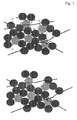
- the reverse microemulsion directed synthesis of PEDOT lead to the formation of nanosized mesh (not shown or shown in Fig.5 ).
- the porous structure is formed from the agglomeration of individual PEDOT nanostubs.
- the conductive porous nanomesh of PEDOT particles completely wraps the LiFePO 4 particles thus rendering the whole composite to be much more conductive.
- PEDOT particles also act as a binder to bind the electrode ingredients together and with the current collector. This makes the use of any separate binder unnecessary hence alleviating inactive mass from the bulk of the electrode.
- Fig. 7 shows the initial discharge capacity of all three samples cycled at a specific current of 20 mA ( ⁇ 0.1 C). All the samples have an exceptional flat voltage plateau. At this relatively low current both the carbon coated sample (LC) and the polymer composite sample (LP) boast a capacity around 166 mAh g -1 which is very close to the theoretical capacity of 170 mAH g -1 for LiFePO 4 .
- the uncoated sample (L1) has a start capacity of 110 mAh g -1 which is significantly lower than the other two samples. For all three samples the discharge capacity at this current remains stable for a very high number of cycles. This discrepancy in performance clearly illustrates the influence of conductivity on the performance of the electrode.
- Fig. 8a and Fig. 8b compare the performance of LC and LP at a specific current of 135 mAh g -1 ( ⁇ 0.8C).
- the initial discharge capacity of LP is 158.5 mAh g -1 .
- Figure 8a shows the subsequent discharge curves for the 10 th , 50 th and 100 th cycle. The capacities at these cycles are 158 mAh g -1 , 159 mAh g -1 and 141 mAh g -1 , respectively. This represents a drop of around 0.17 mAh g -1 per cycle and implies that 90 % of the initial discharge capacity is retained after 100 cycles.
- the sample LC has a initial discharge capacity of 145 mAh g -1 which is followed by 128 mAh g -1 , 112 mAh g -1 and 97 mAh g -1 for the 10 th , 50 th and 100 th cycle respectively. This represents a drop of around 0.33 mAh g -1 per cycle and only 67 % of the original capacity is retained after 100 cycles. Hence for LP both the start capacity and the capacity retention are significantly better than LC. Both the sample show almost linear decline with the same rate for the next 100 cycles as show in Fig. 9 .
- the final discharge capacity of LP after 200 cycles is 130 mAh g -1 compared to 56 mAh g -1 for LC.
- Fig. 8a show the differential specific capacity plots (DSCP) for both these samples at the corresponding 10 th , 50 th and 100 th discharge cycle.
- the peak of these differential specific capacity plots corresponds to the anodic and cathodic plateau of the lithium intercalation/deintercalation from the active material. Both the anodic and the cathodic peak occur around 3.4 V which is the lithium extraction/insertion potential in LiFePO 4 .
- the main differences between the two plots are the polarization gap between the anodic and the cathodic peak and the intensity of the peaks.
- the separation is around 0.1 V whereas its 0.6 V in LC. This separation indicates the amount of overpotential in the electrode mix which primarily suggests higher electrode resistance in LC.
- the peak intensity of the polymer composite LP is much higher than LC which indicates better Li insertion kinetics than the latter.
- Fig. 10 depicts the discharge potential as a function of number of cycles at various currents. At C/5 the samples exhibits an almost theoretical capacity of 170 mAh g -1 . This value steadily decreases with the increase of current but even at a high current corresponding to 10C a relatively steady discharge capacity of around 130 mAh g -1 is observed. After the current is dropped to its initial value most of the original capacity is retained.
- the performance of the composite of PEDOT and LiFePO 4 was significantly better compared to the bare and carbon coated LiFePO 4 .
- the conductive polymer containing composite outperforms the other two samples while having only 50 % of their total additive content with respect to the weight of the electrode.
Landscapes
- Chemical & Material Sciences (AREA)
- General Chemical & Material Sciences (AREA)
- Chemical Kinetics & Catalysis (AREA)
- Electrochemistry (AREA)
- Engineering & Computer Science (AREA)
- Manufacturing & Machinery (AREA)
- Inorganic Chemistry (AREA)
- Materials Engineering (AREA)
- Composite Materials (AREA)
- Crystallography & Structural Chemistry (AREA)
- Battery Electrode And Active Subsutance (AREA)
Priority Applications (6)
| Application Number | Priority Date | Filing Date | Title |
|---|---|---|---|
| EP09157135.6A EP2237346B1 (fr) | 2009-04-01 | 2009-04-01 | Matériau nano-composite conducteur électriquement comportant des nanoparticules de sacrifice et nano-composites poreuses ouvertes produites ainsi |
| US12/721,669 US8507135B2 (en) | 2009-04-01 | 2010-03-11 | Electrically conductive nanocomposite material comprising sacrificial nanoparticles and open porous nanocomposites produced thereof |
| JP2010056719A JP5650418B2 (ja) | 2009-03-12 | 2010-03-12 | 犠牲ナノ粒子を含む電気伝導性ナノ複合材料およびそれから生成される開放多孔質ナノ複合材 |
| TW099107290A TWI458165B (zh) | 2009-04-01 | 2010-03-12 | 包含犠牲性奈米粒子及其所產生之開孔式奈米複合物之導電性奈米複合物材料 |
| KR1020100022498A KR101316413B1 (ko) | 2009-03-12 | 2010-03-12 | 희생 나노입자를 포함하는 전기 전도성 나노복합체 물질 및 이에 의해 생산된 개방 다공성 나노복합체 |
| CN201010190574.1A CN102142536B (zh) | 2009-04-01 | 2010-03-12 | 导电纳米复合材料及由其制成的开口多孔纳米复合物 |
Applications Claiming Priority (1)
| Application Number | Priority Date | Filing Date | Title |
|---|---|---|---|
| EP09157135.6A EP2237346B1 (fr) | 2009-04-01 | 2009-04-01 | Matériau nano-composite conducteur électriquement comportant des nanoparticules de sacrifice et nano-composites poreuses ouvertes produites ainsi |
Publications (2)
| Publication Number | Publication Date |
|---|---|
| EP2237346A1 true EP2237346A1 (fr) | 2010-10-06 |
| EP2237346B1 EP2237346B1 (fr) | 2017-08-09 |
Family
ID=41000015
Family Applications (1)
| Application Number | Title | Priority Date | Filing Date |
|---|---|---|---|
| EP09157135.6A Active EP2237346B1 (fr) | 2009-03-12 | 2009-04-01 | Matériau nano-composite conducteur électriquement comportant des nanoparticules de sacrifice et nano-composites poreuses ouvertes produites ainsi |
Country Status (4)
| Country | Link |
|---|---|
| US (1) | US8507135B2 (fr) |
| EP (1) | EP2237346B1 (fr) |
| CN (1) | CN102142536B (fr) |
| TW (1) | TWI458165B (fr) |
Cited By (11)
| Publication number | Priority date | Publication date | Assignee | Title |
|---|---|---|---|---|
| US20100308277A1 (en) * | 2009-04-01 | 2010-12-09 | The Swatch Group Research And Development Ltd | Electrically conductive nanocomposite material comprising sacrificial nanoparticles and open porous nanocomposites produced thereof |
| WO2012046791A1 (fr) * | 2010-10-08 | 2012-04-12 | Semiconductor Energy Laboratory Co., Ltd. | Procédé de fabrication de matériau actif d'électrode positive pour dispositif de stockage d'énergie, et dispositif de stockage d'énergie |
| WO2012046669A1 (fr) * | 2010-10-08 | 2012-04-12 | Semiconductor Energy Laboratory Co., Ltd. | Matériau actif d'électrode positive et dispositif de stockage de puissance |
| WO2013185837A1 (fr) * | 2012-06-15 | 2013-12-19 | MAX-PLANCK-Gesellschaft zur Förderung der Wissenschaften e.V. | Procédé de fabrication d'un matériau d'électrode, et matériau d'électrode |
| EP2758340A1 (fr) * | 2011-09-19 | 2014-07-30 | Hydro-Québec | Matériaux d'anode particulaires et procédé de préparation associés |
| US9218916B2 (en) | 2011-06-24 | 2015-12-22 | Semiconductor Energy Laboratory Co., Ltd. | Graphene, power storage device, and electric device |
| US9761867B2 (en) | 2009-03-12 | 2017-09-12 | Belenos Clean Power Holding Ag | Open porous electrically conductive nanocomposite material |
| US10135069B2 (en) | 2010-10-08 | 2018-11-20 | Semiconductor Energy Laboratory Co., Ltd. | Electrode material and method for manufacturing power storage device |
| US10461332B2 (en) | 2011-09-30 | 2019-10-29 | Semiconductor Energy Laboratory Co., Ltd. | Graphene and power storage device, and manufacturing method thereof |
| US10644315B2 (en) | 2011-06-03 | 2020-05-05 | Semiconductor Energy Laboratory Co., Ltd. | Single-layer and multilayer graphene, method of manufacturing the same, object including the same, and electric device including the same |
| US11296322B2 (en) | 2011-06-03 | 2022-04-05 | Semiconductor Energy Laboratory Co., Ltd. | Single-layer and multilayer graphene, method of manufacturing the same, object including the same, and electric device including the same |
Families Citing this family (48)
| Publication number | Priority date | Publication date | Assignee | Title |
|---|---|---|---|---|
| CN106207082A (zh) | 2010-08-19 | 2016-12-07 | 株式会社半导体能源研究所 | 电气设备 |
| US8652386B2 (en) | 2010-09-16 | 2014-02-18 | Georgia Tech Research Corporation | Alignment of carbon nanotubes comprising magnetically sensitive metal oxides in nanofluids |
| EP2698851B1 (fr) * | 2011-04-13 | 2018-12-12 | Sei Corporation | Matériau d'électrode pour accumulateur au lithium et accumulateur au lithium |
| KR102036624B1 (ko) | 2011-06-03 | 2019-10-28 | 가부시키가이샤 한도오따이 에네루기 켄큐쇼 | 전극의 제조 방법 |
| JP6025284B2 (ja) | 2011-08-19 | 2016-11-16 | 株式会社半導体エネルギー研究所 | 蓄電装置用の電極及び蓄電装置 |
| WO2013027561A1 (fr) | 2011-08-19 | 2013-02-28 | Semiconductor Energy Laboratory Co., Ltd. | Procédé permettant de fabriquer un objet revêtu de graphène, électrode négative de batterie rechargeable incluant l'objet revêtu de graphène et batterie rechargeable incluant l'électrode négative |
| KR20130024769A (ko) | 2011-08-30 | 2013-03-08 | 가부시키가이샤 한도오따이 에네루기 켄큐쇼 | 축전 장치 |
| US9249524B2 (en) | 2011-08-31 | 2016-02-02 | Semiconductor Energy Laboratory Co., Ltd. | Manufacturing method of composite oxide and manufacturing method of power storage device |
| JP6000017B2 (ja) | 2011-08-31 | 2016-09-28 | 株式会社半導体エネルギー研究所 | 蓄電装置及びその作製方法 |
| JP6029898B2 (ja) | 2011-09-09 | 2016-11-24 | 株式会社半導体エネルギー研究所 | リチウム二次電池用正極の作製方法 |
| US9401247B2 (en) | 2011-09-21 | 2016-07-26 | Semiconductor Energy Laboratory Co., Ltd. | Negative electrode for power storage device and power storage device |
| JP6218349B2 (ja) | 2011-09-30 | 2017-10-25 | 株式会社半導体エネルギー研究所 | 蓄電装置 |
| CA2754372A1 (fr) | 2011-10-04 | 2013-04-04 | Hydro-Quebec | Materiau d'electrode positive pour batterie secondaire au lihium-ion et methode de production connexe |
| CN103035922B (zh) | 2011-10-07 | 2019-02-19 | 株式会社半导体能源研究所 | 蓄电装置 |
| US9487880B2 (en) | 2011-11-25 | 2016-11-08 | Semiconductor Energy Laboratory Co., Ltd. | Flexible substrate processing apparatus |
| JP6016597B2 (ja) | 2011-12-16 | 2016-10-26 | 株式会社半導体エネルギー研究所 | リチウムイオン二次電池用正極の製造方法 |
| JP6009343B2 (ja) | 2011-12-26 | 2016-10-19 | 株式会社半導体エネルギー研究所 | 二次電池用正極および二次電池用正極の作製方法 |
| US9680272B2 (en) | 2012-02-17 | 2017-06-13 | Semiconductor Energy Laboratory Co., Ltd. | Method for forming negative electrode and method for manufacturing lithium secondary battery |
| JP5719859B2 (ja) | 2012-02-29 | 2015-05-20 | 株式会社半導体エネルギー研究所 | 蓄電装置 |
| JP6077347B2 (ja) | 2012-04-10 | 2017-02-08 | 株式会社半導体エネルギー研究所 | 非水系二次電池用正極の製造方法 |
| US9225003B2 (en) | 2012-06-15 | 2015-12-29 | Semiconductor Energy Laboratory Co., Ltd. | Method for manufacturing storage battery electrode, storage battery electrode, storage battery, and electronic device |
| JP6207923B2 (ja) | 2012-08-27 | 2017-10-04 | 株式会社半導体エネルギー研究所 | 二次電池用正極の製造方法 |
| JP6159228B2 (ja) | 2012-11-07 | 2017-07-05 | 株式会社半導体エネルギー研究所 | 非水系二次電池用正極の製造方法 |
| US9673454B2 (en) | 2013-02-18 | 2017-06-06 | Semiconductor Energy Laboratory Co., Ltd. | Sodium-ion secondary battery |
| US9490472B2 (en) | 2013-03-28 | 2016-11-08 | Semiconductor Energy Laboratory Co., Ltd. | Method for manufacturing electrode for storage battery |
| KR20140121953A (ko) | 2013-04-08 | 2014-10-17 | 주식회사 엘지화학 | 리튬 이차전지용 음극, 그 제조방법 및 이를 포함하는 리튬 이차 전지 |
| KR101580030B1 (ko) | 2013-07-09 | 2015-12-23 | 주식회사 엘지화학 | 탄소 코팅 리튬 인산철 나노분말의 제조방법 |
| US20150044560A1 (en) | 2013-08-09 | 2015-02-12 | Semiconductor Energy Laboratory Co., Ltd. | Electrode for lithium-ion secondary battery and manufacturing method thereof, and lithium-ion secondary battery |
| US9312046B2 (en) | 2014-02-12 | 2016-04-12 | South Dakota Board Of Regents | Composite materials with magnetically aligned carbon nanoparticles having enhanced electrical properties and methods of preparation |
| WO2015157249A1 (fr) * | 2014-04-07 | 2015-10-15 | Johnson Ip Holding, Llc | Anode a base de lithium presentant une structure nanocomposite et procede de fabrication correspondant |
| WO2015164848A1 (fr) | 2014-04-25 | 2015-10-29 | South Dakota Board Of Regents | Électrodes à haute capacité |
| US11639425B2 (en) * | 2014-05-12 | 2023-05-02 | The Trustees Of The University Of Pennsylvania | Nanocomposite films and methods for producing the same |
| JP6745587B2 (ja) | 2014-05-29 | 2020-08-26 | 株式会社半導体エネルギー研究所 | 電極の製造方法 |
| DE102014214899A1 (de) * | 2014-07-30 | 2016-02-04 | Bayerische Motoren Werke Aktiengesellschaft | Kompositelektrode für eine elektrochemische Zelle und elektrochemische Zelle |
| US10414145B2 (en) | 2014-08-27 | 2019-09-17 | 3M Innovative Properties Company | Electrical multilayer lamination transfer films |
| CN104638242A (zh) * | 2015-02-06 | 2015-05-20 | 重庆特瑞电池材料股份有限公司 | 原位聚合包覆合成锂离子电池正极材料磷酸铁锂的方法 |
| US10614965B2 (en) * | 2015-11-13 | 2020-04-07 | Clarkson University | Activated carbons from dairy products |
| CN106571244A (zh) * | 2016-11-02 | 2017-04-19 | 南京工业大学 | 二维过渡族金属碳(氮)化合物与二维过渡族金属硫化物纳米复合粉体及制备和应用 |
| CN106784724B (zh) * | 2017-01-12 | 2020-08-07 | 吉林大学 | 一种LiFePO4@C/rGO多级复合微球的溶剂热辅助制备方法 |
| JP6332540B1 (ja) * | 2017-09-29 | 2018-05-30 | 住友大阪セメント株式会社 | リチウムイオン二次電池用正極材料、リチウムイオン二次電池用正極、リチウムイオン二次電池 |
| CN107768627A (zh) * | 2017-10-03 | 2018-03-06 | 长沙仲善新能源科技有限公司 | 一种高温稳定性镍钴锰酸锂复合电极及其制备方法与应用 |
| JP2019096610A (ja) | 2017-11-21 | 2019-06-20 | 三星電子株式会社Samsung Electronics Co.,Ltd. | 全固体二次電池およびその充電方法 |
| US10468674B2 (en) | 2018-01-09 | 2019-11-05 | South Dakota Board Of Regents | Layered high capacity electrodes |
| US11437643B2 (en) | 2018-02-20 | 2022-09-06 | Samsung Electronics Co., Ltd. | All-solid-state secondary battery |
| US20220115646A1 (en) * | 2019-01-22 | 2022-04-14 | Xg Sciences, Inc. | Silicon/graphene composite anode material and method to manufacture the same |
| US11824155B2 (en) | 2019-05-21 | 2023-11-21 | Samsung Electronics Co., Ltd. | All-solid lithium secondary battery and method of charging the same |
| KR20210048291A (ko) | 2019-10-23 | 2021-05-03 | 삼성전자주식회사 | 금속공기전지용 양극, 그 제조방법 및 이를 포함하는 금속공기전지 |
| CN112394568B (zh) * | 2020-12-15 | 2022-09-13 | 厦门天马微电子有限公司 | 显示面板及显示装置 |
Citations (5)
| Publication number | Priority date | Publication date | Assignee | Title |
|---|---|---|---|---|
| WO2001041238A1 (fr) | 1999-12-03 | 2001-06-07 | Ferro Gmbh | Materiau d'electrode pour electrodes positives de piles au lithium rechargeables |
| US20020192551A1 (en) * | 1999-10-29 | 2002-12-19 | Hiroshi Yoshizawa | Nonaqueous electrolyte battery |
| US20040241532A1 (en) * | 2003-06-02 | 2004-12-02 | Kim Young Nam | Carbon nanotube or carbon nanofiber electrode comprising sulfur or metal nanoparticles as a binder and process for preparing the same |
| US20070054187A1 (en) | 2003-11-14 | 2007-03-08 | Süd-Chemie AG | Lithium metal phosphates, method for producing the same and use thereof as electrode material |
| EP1881544A1 (fr) * | 2005-01-26 | 2008-01-23 | Shirouma Science Co., Ltd. | Mareriau d electrode positive pour pile secondaire au lithium |
Family Cites Families (37)
| Publication number | Priority date | Publication date | Assignee | Title |
|---|---|---|---|---|
| US2007105A (en) * | 1933-07-18 | 1935-07-02 | Firm Bulova Watch Company Inc | Self-winding wrist watch |
| DE3890245C2 (fr) * | 1987-04-15 | 1992-12-10 | Ricoh Co., Ltd., Tokio/Tokyo, Jp | |
| JPH0817094B2 (ja) * | 1989-11-24 | 1996-02-21 | セントラル硝子株式会社 | 電極材料およびその製造法 |
| US5418090A (en) * | 1993-02-17 | 1995-05-23 | Valence Technology, Inc. | Electrodes for rechargeable lithium batteries |
| DE69711262T2 (de) | 1996-05-31 | 2002-12-12 | Matsushita Electric Industrial Co., Ltd. | Akkumulator mit nichtwässrigem Elektrolyt |
| JP4172443B2 (ja) | 1996-07-19 | 2008-10-29 | ソニー株式会社 | 非水電解液二次電池用負極材料及び非水電解液二次電池 |
| JP3526707B2 (ja) | 1996-11-27 | 2004-05-17 | 株式会社トクヤマ | 非水電解液二次電池用負極活物質および非水電解液二次電池 |
| JP4453111B2 (ja) | 1997-10-27 | 2010-04-21 | 三菱化学株式会社 | 負極材料とその製造方法、負極活物質、および非水系二次電池 |
| JP4078698B2 (ja) | 1997-12-03 | 2008-04-23 | 宇部興産株式会社 | 非水二次電池用負極材料とその製造方法および電池 |
| JP4106644B2 (ja) | 2000-04-04 | 2008-06-25 | ソニー株式会社 | 電池およびその製造方法 |
| US7387851B2 (en) * | 2001-07-27 | 2008-06-17 | A123 Systems, Inc. | Self-organizing battery structure with electrode particles that exert a repelling force on the opposite electrode |
| CA2327370A1 (fr) * | 2000-12-05 | 2002-06-05 | Hydro-Quebec | Nouvelle methode de fabrication de li4ti5o12 pur a partir du compose ternaire tix-liy-carbone: effet du carbone sur la synthese et la conductivite de l'electrode |
| EP1244168A1 (fr) * | 2001-03-20 | 2002-09-25 | Francois Sugnaux | Electrode à réseau mésoporeux pour batterie |
| EP1244114A1 (fr) | 2001-03-20 | 2002-09-25 | ILFORD Imaging Switzerland GmbH | Films électro-actifs |
| AU2002330924A1 (en) * | 2001-07-27 | 2003-02-17 | A 123 Systems | Battery structures, self-organizing structures and related methods |
| MXPA04007623A (es) * | 2002-02-07 | 2004-12-07 | Fuji Jukogyo Kabushiki Kaisya | Electrodo reversible activo de reduccion oxidacion y bateria novedosa que utiliza el mismo. |
| JP2004022507A (ja) * | 2002-06-20 | 2004-01-22 | Sony Corp | 電極およびそれを用いた電池 |
| JP3586270B2 (ja) | 2002-08-15 | 2004-11-10 | 株式会社東芝 | 正極活物質及び非水電解質電池 |
| CA2432397A1 (fr) * | 2003-06-25 | 2004-12-25 | Hydro-Quebec | Procede de preparation d'electrode a partir d'un silicium poreux, electrode ainsi obtenue et systeme electrochimique contenant au moins une telle electrode |
| KR100601090B1 (ko) * | 2003-10-14 | 2006-07-14 | 주식회사 엘지화학 | 다공성 템플레이트를 이용하여 제조된 고표면적 전극시스템 및 이를 이용한 전기 소자 |
| KR100537745B1 (ko) * | 2004-06-21 | 2005-12-19 | 한국전기연구원 | 리튬이차전지용 음극 활물질 및 그 제조방법 |
| US7927742B2 (en) * | 2004-10-29 | 2011-04-19 | Medtronic, Inc. | Negative-limited lithium-ion battery |
| DE102004053479A1 (de) | 2004-11-05 | 2006-05-11 | Dilo Trading Ag | Hochleistungsbatterien mit Titanaten als negativem und Eisenphosphat als positivem Elektrodenmaterial und Verfahren zur Herstellung der Hochleistungsbatterien |
| US7615314B2 (en) * | 2004-12-10 | 2009-11-10 | Canon Kabushiki Kaisha | Electrode structure for lithium secondary battery and secondary battery having such electrode structure |
| KR100682862B1 (ko) * | 2005-01-11 | 2007-02-15 | 삼성에스디아이 주식회사 | 전기 화학 전지용 전극, 그 제조 방법 및 이를 채용한전기 화학 전지 |
| FR2885734B1 (fr) | 2005-05-13 | 2013-07-05 | Accumulateurs Fixes | Materiau nanocomposite pour anode d'accumulateur au lithium |
| US7968231B2 (en) * | 2005-12-23 | 2011-06-28 | U Chicago Argonne, Llc | Electrode materials and lithium battery systems |
| JP5142515B2 (ja) | 2006-12-19 | 2013-02-13 | 三洋電機株式会社 | 非水電解質二次電池 |
| CA2677338A1 (fr) * | 2007-02-07 | 2008-08-14 | Valence Technology, Inc. | Materiaux d'electrode actifs a base d'oxynitrure pour cellules electrochimiques secondaires |
| US8039152B2 (en) * | 2007-04-03 | 2011-10-18 | Toyota Motor Engineering & Manufacturing North America, Inc. | Tin in an active support matrix |
| US8936874B2 (en) * | 2008-06-04 | 2015-01-20 | Nanotek Instruments, Inc. | Conductive nanocomposite-based electrodes for lithium batteries |
| JP5684462B2 (ja) * | 2008-12-22 | 2015-03-11 | 昭和電工パッケージング株式会社 | 正極タブリード及び電池 |
| US8241793B2 (en) * | 2009-01-02 | 2012-08-14 | Nanotek Instruments, Inc. | Secondary lithium ion battery containing a prelithiated anode |
| US9093693B2 (en) * | 2009-01-13 | 2015-07-28 | Samsung Electronics Co., Ltd. | Process for producing nano graphene reinforced composite particles for lithium battery electrodes |
| EP2228855B1 (fr) * | 2009-03-12 | 2014-02-26 | Belenos Clean Power Holding AG | Matériau nano-composite conducteur électriquement poreux ouvert |
| EP2237346B1 (fr) * | 2009-04-01 | 2017-08-09 | The Swatch Group Research and Development Ltd. | Matériau nano-composite conducteur électriquement comportant des nanoparticules de sacrifice et nano-composites poreuses ouvertes produites ainsi |
| US8624105B2 (en) * | 2009-05-01 | 2014-01-07 | Synkera Technologies, Inc. | Energy conversion device with support member having pore channels |
-
2009
- 2009-04-01 EP EP09157135.6A patent/EP2237346B1/fr active Active
-
2010
- 2010-03-11 US US12/721,669 patent/US8507135B2/en active Active
- 2010-03-12 TW TW099107290A patent/TWI458165B/zh not_active IP Right Cessation
- 2010-03-12 CN CN201010190574.1A patent/CN102142536B/zh active Active
Patent Citations (5)
| Publication number | Priority date | Publication date | Assignee | Title |
|---|---|---|---|---|
| US20020192551A1 (en) * | 1999-10-29 | 2002-12-19 | Hiroshi Yoshizawa | Nonaqueous electrolyte battery |
| WO2001041238A1 (fr) | 1999-12-03 | 2001-06-07 | Ferro Gmbh | Materiau d'electrode pour electrodes positives de piles au lithium rechargeables |
| US20040241532A1 (en) * | 2003-06-02 | 2004-12-02 | Kim Young Nam | Carbon nanotube or carbon nanofiber electrode comprising sulfur or metal nanoparticles as a binder and process for preparing the same |
| US20070054187A1 (en) | 2003-11-14 | 2007-03-08 | Süd-Chemie AG | Lithium metal phosphates, method for producing the same and use thereof as electrode material |
| EP1881544A1 (fr) * | 2005-01-26 | 2008-01-23 | Shirouma Science Co., Ltd. | Mareriau d electrode positive pour pile secondaire au lithium |
Non-Patent Citations (17)
| Title |
|---|
| A. YAMADA; S. C. CHUNG; K. HINOKUMA, J. ELECTROCHEM. SOC., vol. 148, 2001, pages A224 |
| CHUNG, S.-Y.; BLOKING, J.T.; CHIANG, Y.-M., NATURE MATER., vol. 1, 2002, pages 123 |
| F. CROCE ET AL., ELECTROCHEM. SOLID-STATE LETT., vol. 5, 2002, pages A47 |
| G. HEYWANG; F. JONAS, ADV. MATER., vol. 4, 1992, pages 116 |
| H. YAMATO; M. OHWA; W. WERNET., J. ELECTROANAL. CHEM., vol. 397, 1995, pages 136 |
| L. B. GROENENDAAL ET AL., ADV. MATER. WEINHEIM, GER., vol. 12, 2000, pages 481 |
| M. E. SPAHR, SYNTHESE UND CHARAKTERISIERUNG NEUARTIGER OXIDE, KOHLENSTOFFVERBINDUNGEN, SILICIDE SOWIE NANOSTRUKTURIERTER MATERIALIEN UND DEREN ELEKTRO- UND MAGNETOCHEMISCHE UNTERSUCHUNG |
| MARTIN WINTER ET AL.: "Insertion Electrode Materials for Rechargeable Lithium Batteries", ADVANCED MATERIALS, vol. 10, 10 November 1998 (1998-11-10), pages 725 - 763 |
| PADHI, A.K.; NANJUNDASWAMY, K.S.; GOODENOUGH, J.B., J. ELECTROCHEM. SOC., vol. 144, 1997, pages 1188 |
| PROSINI, P.P.; ZANE, D.; PASQUALI, M., ELECTROCHIM. ACTA., vol. 46, 2001, pages 3517 |
| S. FRANGER ET AL., ELECTROCHEM. SOLID-STATE LETT., vol. 5, 2002, pages A231 |
| S. FRANGER ET AL., J. POWER SOURCES, vol. 119, 2003, pages 252 |
| S. YANG; P.Y. ZAVALIJ; M.S. WHITTINGHAM, ELECTROCHEM. COMMUN., vol. 3, 2001, pages 505 |
| S.Y. CHUNG; Y.-M. CHIANG, ELECTROCHEM. SOLID-STATE LETT., vol. 6, 2003, pages A278 |
| WINTER ET AL., CHEM. PHYS., vol. 194, 1995, pages 207 |
| YONG-JUN LI; WEI-JUN HUANG; SHI-GANG SUN., ANGEW. CHEM., vol. 118, 2006, pages 2599 |
| ZHAOHUI CHEN; J. R. DAHN, J. ELECTROCHEM. SOC., vol. 149, 2002, pages A1184 |
Cited By (24)
| Publication number | Priority date | Publication date | Assignee | Title |
|---|---|---|---|---|
| US9761867B2 (en) | 2009-03-12 | 2017-09-12 | Belenos Clean Power Holding Ag | Open porous electrically conductive nanocomposite material |
| US20100308277A1 (en) * | 2009-04-01 | 2010-12-09 | The Swatch Group Research And Development Ltd | Electrically conductive nanocomposite material comprising sacrificial nanoparticles and open porous nanocomposites produced thereof |
| US8507135B2 (en) * | 2009-04-01 | 2013-08-13 | The Swatch Group Research And Development Ltd | Electrically conductive nanocomposite material comprising sacrificial nanoparticles and open porous nanocomposites produced thereof |
| WO2012046669A1 (fr) * | 2010-10-08 | 2012-04-12 | Semiconductor Energy Laboratory Co., Ltd. | Matériau actif d'électrode positive et dispositif de stockage de puissance |
| US10135069B2 (en) | 2010-10-08 | 2018-11-20 | Semiconductor Energy Laboratory Co., Ltd. | Electrode material and method for manufacturing power storage device |
| US9490474B2 (en) | 2010-10-08 | 2016-11-08 | Semiconductor Energy Laboratory Co., Ltd. | Method for manufacturing positive electrode active material for energy storage device and energy storage device |
| TWI559601B (zh) * | 2010-10-08 | 2016-11-21 | 半導體能源研究所股份有限公司 | 製造能量儲存裝置的正極活性材料之方法及能量儲存裝置 |
| WO2012046791A1 (fr) * | 2010-10-08 | 2012-04-12 | Semiconductor Energy Laboratory Co., Ltd. | Procédé de fabrication de matériau actif d'électrode positive pour dispositif de stockage d'énergie, et dispositif de stockage d'énergie |
| US10164243B2 (en) | 2010-10-08 | 2018-12-25 | Semiconductor Energy Laboratory Co., Ltd. | Method for manufacturing positive electrode active material for energy storage device and energy storage device |
| US11699790B2 (en) | 2011-06-03 | 2023-07-11 | Semiconductor Energy Laboratory Co., Ltd. | Single-layer and multilayer graphene, method of manufacturing the same, object including the same, and electric device including the same |
| US11296322B2 (en) | 2011-06-03 | 2022-04-05 | Semiconductor Energy Laboratory Co., Ltd. | Single-layer and multilayer graphene, method of manufacturing the same, object including the same, and electric device including the same |
| US10644315B2 (en) | 2011-06-03 | 2020-05-05 | Semiconductor Energy Laboratory Co., Ltd. | Single-layer and multilayer graphene, method of manufacturing the same, object including the same, and electric device including the same |
| US9218916B2 (en) | 2011-06-24 | 2015-12-22 | Semiconductor Energy Laboratory Co., Ltd. | Graphene, power storage device, and electric device |
| US9653728B2 (en) | 2011-06-24 | 2017-05-16 | Semiconductor Energy Laboratory Co., Ltd. | Graphene, power storage device, and electric device |
| EP2758340A4 (fr) * | 2011-09-19 | 2015-03-11 | Hydro Québec | Matériaux d'anode particulaires et procédé de préparation associés |
| US9837662B2 (en) | 2011-09-19 | 2017-12-05 | Hydro-Quebec | Particulate anode materials and methods for their preparation |
| EP3546093A1 (fr) * | 2011-09-19 | 2019-10-02 | Hydro-Québec | Matériaux d'anode particulaires et procédé de préparation associés |
| US9559355B2 (en) | 2011-09-19 | 2017-01-31 | HYDRO-QUéBEC | Particulate anode materials and methods for their preparation |
| EP2758340A1 (fr) * | 2011-09-19 | 2014-07-30 | Hydro-Québec | Matériaux d'anode particulaires et procédé de préparation associés |
| US10461332B2 (en) | 2011-09-30 | 2019-10-29 | Semiconductor Energy Laboratory Co., Ltd. | Graphene and power storage device, and manufacturing method thereof |
| US11735731B2 (en) | 2011-09-30 | 2023-08-22 | Semiconductor Energy Laboratory Co., Ltd. | Graphene and power storage device, and manufacturing method thereof |
| US11990621B2 (en) | 2011-09-30 | 2024-05-21 | Semiconductor Energy Laboratory Co., Ltd. | Graphene and power storage device, and manufacturing method thereof |
| US9954220B2 (en) | 2012-06-15 | 2018-04-24 | Max-Planck-Gesellschaft Zur Forderung Der Wissenschaften E.V. | Method of manufacture of an electrode material and an electrode material |
| WO2013185837A1 (fr) * | 2012-06-15 | 2013-12-19 | MAX-PLANCK-Gesellschaft zur Förderung der Wissenschaften e.V. | Procédé de fabrication d'un matériau d'électrode, et matériau d'électrode |
Also Published As
| Publication number | Publication date |
|---|---|
| CN102142536B (zh) | 2014-12-10 |
| US8507135B2 (en) | 2013-08-13 |
| TWI458165B (zh) | 2014-10-21 |
| TW201101563A (en) | 2011-01-01 |
| US20100308277A1 (en) | 2010-12-09 |
| CN102142536A (zh) | 2011-08-03 |
| EP2237346B1 (fr) | 2017-08-09 |
Similar Documents
| Publication | Publication Date | Title |
|---|---|---|
| EP2237346B1 (fr) | Matériau nano-composite conducteur électriquement comportant des nanoparticules de sacrifice et nano-composites poreuses ouvertes produites ainsi | |
| EP2228855B1 (fr) | Matériau nano-composite conducteur électriquement poreux ouvert | |
| KR101316413B1 (ko) | 희생 나노입자를 포함하는 전기 전도성 나노복합체 물질 및 이에 의해 생산된 개방 다공성 나노복합체 | |
| Kim et al. | Effect of mechanical activation process parameters on the properties of LiFePO4 cathode material | |
| Kim et al. | High-performance FeSb–TiC–C nanocomposite anodes for sodium-ion batteries | |
| US9515310B2 (en) | V2O5 electrodes with high power and energy densities | |
| Zhu et al. | Multifunctional vanadium nitride@ N-doped carbon composites for kinetically enhanced lithium–sulfur batteries | |
| Zou et al. | Preparation of carbon-coated LiFe0. 2Mn0. 8PO4 cathode material and its application in a novel battery with Li4Ti5O12 anode | |
| Morales et al. | Cycling-induced stress in lithium ion negative electrodes: LiAl/LiFePO4 and Li4Ti5O12/LiFePO4 cells | |
| Yang et al. | Cation disordered rock salt phase Li 2 CoTiO 4 as a potential cathode material for Li-ion batteries | |
| US20140356705A1 (en) | ENCAPSULATED Li2S NANOPARTICLES FOR Li/S BATTERIES WITH ULTRAHIGH ENERGY DENSITIES AND LONG CYCLE LIFE | |
| KR102229454B1 (ko) | 수산화철(FeOOH)의 제조방법 및 수산화철을 포함하는 리튬-황 전지용 양극 | |
| Sun et al. | Nano-MgO/AB decorated separator to suppress shuttle effect of lithium–sulfur battery | |
| Kim et al. | Properties of lithium iron phosphate prepared by biomass-derived carbon coating for flexible lithium ion batteries | |
| Kim et al. | Effect of synthetic conditions on the electrochemical properties of LiMn0. 4Fe0. 6PO4/C synthesized by sol–gel technique | |
| CN113506861A (zh) | 一种锂离子电池硅基复合负极材料及其制备方法 | |
| Zeng et al. | Micro-sized FeS2@ FeSO4 core-shell composite for advanced lithium storage | |
| WO2018156355A1 (fr) | Particules cœur-écorce électrochimiquement actives à microstructure modifiée et leur utilisation pour des électrodes d'accumulateurs | |
| JP2020145108A (ja) | 電極材料、該電極材料の製造方法、電極、及びリチウムイオン電池 | |
| CN117543009A (zh) | 磷酸盐系正极材料及其制备方法和应用 | |
| Yu et al. | Pomegranate-like gallium oxide nanospheres coated with nitrogen-doped carbon as an anode for lithium-ion batteries with an ultra-long cycle life | |
| EP4266411A1 (fr) | Matériau actif d?électrode négative pour batterie rechargeable au lithium, son procédé de préparation, et batterie rechargeable au lithium la comprenant | |
| Wang et al. | Enhanced electrochemical performance of Li3V2 (PO4) 3 structurally converted from LiVOPO4 by graphite nanofiber addition | |
| KR20230005340A (ko) | 전극 재료용 컨포멀 피커링 에멀젼 그래핀 코팅 및 이의 형성 방법 응용 | |
| Zhou et al. | Direct synthesis of carbon sheathed tungsten oxide nanoparticles via self-assembly route for high performance electrochemical charge storage electrode |
Legal Events
| Date | Code | Title | Description |
|---|---|---|---|
| PUAI | Public reference made under article 153(3) epc to a published international application that has entered the european phase |
Free format text: ORIGINAL CODE: 0009012 |
|
| AK | Designated contracting states |
Kind code of ref document: A1 Designated state(s): AT BE BG CH CY CZ DE DK EE ES FI FR GB GR HR HU IE IS IT LI LT LU LV MC MK MT NL NO PL PT RO SE SI SK TR |
|
| 17P | Request for examination filed |
Effective date: 20110406 |
|
| 17Q | First examination report despatched |
Effective date: 20110428 |
|
| REG | Reference to a national code |
Ref country code: DE Ref legal event code: R079 Ref document number: 602009047602 Country of ref document: DE Free format text: PREVIOUS MAIN CLASS: H01M0004020000 Ipc: H01M0004134000 |
|
| GRAP | Despatch of communication of intention to grant a patent |
Free format text: ORIGINAL CODE: EPIDOSNIGR1 |
|
| RIC1 | Information provided on ipc code assigned before grant |
Ipc: H01M 4/136 20100101ALI20170424BHEP Ipc: H01M 4/62 20060101ALI20170424BHEP Ipc: H01M 4/36 20060101ALI20170424BHEP Ipc: H01M 4/134 20100101AFI20170424BHEP Ipc: H01M 4/58 20100101ALI20170424BHEP Ipc: H01M 4/04 20060101ALI20170424BHEP Ipc: H01M 10/052 20100101ALI20170424BHEP |
|
| INTG | Intention to grant announced |
Effective date: 20170524 |
|
| GRAS | Grant fee paid |
Free format text: ORIGINAL CODE: EPIDOSNIGR3 |
|
| GRAA | (expected) grant |
Free format text: ORIGINAL CODE: 0009210 |
|
| AK | Designated contracting states |
Kind code of ref document: B1 Designated state(s): AT BE BG CH CY CZ DE DK EE ES FI FR GB GR HR HU IE IS IT LI LT LU LV MC MK MT NL NO PL PT RO SE SI SK TR |
|
| REG | Reference to a national code |
Ref country code: GB Ref legal event code: FG4D |
|
| REG | Reference to a national code |
Ref country code: CH Ref legal event code: EP Ref country code: AT Ref legal event code: REF Ref document number: 917726 Country of ref document: AT Kind code of ref document: T Effective date: 20170815 |
|
| REG | Reference to a national code |
Ref country code: CH Ref legal event code: NV Representative=s name: ICB INGENIEURS CONSEILS EN BREVETS SA, CH |
|
| REG | Reference to a national code |
Ref country code: IE Ref legal event code: FG4D |
|
| REG | Reference to a national code |
Ref country code: DE Ref legal event code: R096 Ref document number: 602009047602 Country of ref document: DE |
|
| REG | Reference to a national code |
Ref country code: NL Ref legal event code: MP Effective date: 20170809 |
|
| REG | Reference to a national code |
Ref country code: LT Ref legal event code: MG4D |
|
| REG | Reference to a national code |
Ref country code: AT Ref legal event code: MK05 Ref document number: 917726 Country of ref document: AT Kind code of ref document: T Effective date: 20170809 |
|
| PG25 | Lapsed in a contracting state [announced via postgrant information from national office to epo] |
Ref country code: LT Free format text: LAPSE BECAUSE OF FAILURE TO SUBMIT A TRANSLATION OF THE DESCRIPTION OR TO PAY THE FEE WITHIN THE PRESCRIBED TIME-LIMIT Effective date: 20170809 Ref country code: FI Free format text: LAPSE BECAUSE OF FAILURE TO SUBMIT A TRANSLATION OF THE DESCRIPTION OR TO PAY THE FEE WITHIN THE PRESCRIBED TIME-LIMIT Effective date: 20170809 Ref country code: AT Free format text: LAPSE BECAUSE OF FAILURE TO SUBMIT A TRANSLATION OF THE DESCRIPTION OR TO PAY THE FEE WITHIN THE PRESCRIBED TIME-LIMIT Effective date: 20170809 Ref country code: SE Free format text: LAPSE BECAUSE OF FAILURE TO SUBMIT A TRANSLATION OF THE DESCRIPTION OR TO PAY THE FEE WITHIN THE PRESCRIBED TIME-LIMIT Effective date: 20170809 Ref country code: NO Free format text: LAPSE BECAUSE OF FAILURE TO SUBMIT A TRANSLATION OF THE DESCRIPTION OR TO PAY THE FEE WITHIN THE PRESCRIBED TIME-LIMIT Effective date: 20171109 Ref country code: NL Free format text: LAPSE BECAUSE OF FAILURE TO SUBMIT A TRANSLATION OF THE DESCRIPTION OR TO PAY THE FEE WITHIN THE PRESCRIBED TIME-LIMIT Effective date: 20170809 Ref country code: HR Free format text: LAPSE BECAUSE OF FAILURE TO SUBMIT A TRANSLATION OF THE DESCRIPTION OR TO PAY THE FEE WITHIN THE PRESCRIBED TIME-LIMIT Effective date: 20170809 |
|
| PG25 | Lapsed in a contracting state [announced via postgrant information from national office to epo] |
Ref country code: ES Free format text: LAPSE BECAUSE OF FAILURE TO SUBMIT A TRANSLATION OF THE DESCRIPTION OR TO PAY THE FEE WITHIN THE PRESCRIBED TIME-LIMIT Effective date: 20170809 Ref country code: PL Free format text: LAPSE BECAUSE OF FAILURE TO SUBMIT A TRANSLATION OF THE DESCRIPTION OR TO PAY THE FEE WITHIN THE PRESCRIBED TIME-LIMIT Effective date: 20170809 Ref country code: IS Free format text: LAPSE BECAUSE OF FAILURE TO SUBMIT A TRANSLATION OF THE DESCRIPTION OR TO PAY THE FEE WITHIN THE PRESCRIBED TIME-LIMIT Effective date: 20171209 Ref country code: LV Free format text: LAPSE BECAUSE OF FAILURE TO SUBMIT A TRANSLATION OF THE DESCRIPTION OR TO PAY THE FEE WITHIN THE PRESCRIBED TIME-LIMIT Effective date: 20170809 Ref country code: BG Free format text: LAPSE BECAUSE OF FAILURE TO SUBMIT A TRANSLATION OF THE DESCRIPTION OR TO PAY THE FEE WITHIN THE PRESCRIBED TIME-LIMIT Effective date: 20171109 Ref country code: GR Free format text: LAPSE BECAUSE OF FAILURE TO SUBMIT A TRANSLATION OF THE DESCRIPTION OR TO PAY THE FEE WITHIN THE PRESCRIBED TIME-LIMIT Effective date: 20171110 |
|
| REG | Reference to a national code |
Ref country code: FR Ref legal event code: PLFP Year of fee payment: 10 |
|
| PG25 | Lapsed in a contracting state [announced via postgrant information from national office to epo] |
Ref country code: CZ Free format text: LAPSE BECAUSE OF FAILURE TO SUBMIT A TRANSLATION OF THE DESCRIPTION OR TO PAY THE FEE WITHIN THE PRESCRIBED TIME-LIMIT Effective date: 20170809 Ref country code: RO Free format text: LAPSE BECAUSE OF FAILURE TO SUBMIT A TRANSLATION OF THE DESCRIPTION OR TO PAY THE FEE WITHIN THE PRESCRIBED TIME-LIMIT Effective date: 20170809 Ref country code: DK Free format text: LAPSE BECAUSE OF FAILURE TO SUBMIT A TRANSLATION OF THE DESCRIPTION OR TO PAY THE FEE WITHIN THE PRESCRIBED TIME-LIMIT Effective date: 20170809 |
|
| REG | Reference to a national code |
Ref country code: DE Ref legal event code: R097 Ref document number: 602009047602 Country of ref document: DE |
|
| PG25 | Lapsed in a contracting state [announced via postgrant information from national office to epo] |
Ref country code: SK Free format text: LAPSE BECAUSE OF FAILURE TO SUBMIT A TRANSLATION OF THE DESCRIPTION OR TO PAY THE FEE WITHIN THE PRESCRIBED TIME-LIMIT Effective date: 20170809 Ref country code: IT Free format text: LAPSE BECAUSE OF FAILURE TO SUBMIT A TRANSLATION OF THE DESCRIPTION OR TO PAY THE FEE WITHIN THE PRESCRIBED TIME-LIMIT Effective date: 20170809 Ref country code: EE Free format text: LAPSE BECAUSE OF FAILURE TO SUBMIT A TRANSLATION OF THE DESCRIPTION OR TO PAY THE FEE WITHIN THE PRESCRIBED TIME-LIMIT Effective date: 20170809 |
|
| PLBE | No opposition filed within time limit |
Free format text: ORIGINAL CODE: 0009261 |
|
| STAA | Information on the status of an ep patent application or granted ep patent |
Free format text: STATUS: NO OPPOSITION FILED WITHIN TIME LIMIT |
|
| 26N | No opposition filed |
Effective date: 20180511 |
|
| PG25 | Lapsed in a contracting state [announced via postgrant information from national office to epo] |
Ref country code: SI Free format text: LAPSE BECAUSE OF FAILURE TO SUBMIT A TRANSLATION OF THE DESCRIPTION OR TO PAY THE FEE WITHIN THE PRESCRIBED TIME-LIMIT Effective date: 20170809 |
|
| PG25 | Lapsed in a contracting state [announced via postgrant information from national office to epo] |
Ref country code: MC Free format text: LAPSE BECAUSE OF FAILURE TO SUBMIT A TRANSLATION OF THE DESCRIPTION OR TO PAY THE FEE WITHIN THE PRESCRIBED TIME-LIMIT Effective date: 20170809 |
|
| REG | Reference to a national code |
Ref country code: BE Ref legal event code: MM Effective date: 20180430 |
|
| GBPC | Gb: european patent ceased through non-payment of renewal fee |
Effective date: 20180401 |
|
| REG | Reference to a national code |
Ref country code: IE Ref legal event code: MM4A |
|
| PG25 | Lapsed in a contracting state [announced via postgrant information from national office to epo] |
Ref country code: LU Free format text: LAPSE BECAUSE OF NON-PAYMENT OF DUE FEES Effective date: 20180401 |
|
| PG25 | Lapsed in a contracting state [announced via postgrant information from national office to epo] |
Ref country code: GB Free format text: LAPSE BECAUSE OF NON-PAYMENT OF DUE FEES Effective date: 20180401 Ref country code: BE Free format text: LAPSE BECAUSE OF NON-PAYMENT OF DUE FEES Effective date: 20180430 |
|
| PG25 | Lapsed in a contracting state [announced via postgrant information from national office to epo] |
Ref country code: IE Free format text: LAPSE BECAUSE OF NON-PAYMENT OF DUE FEES Effective date: 20180401 |
|
| PG25 | Lapsed in a contracting state [announced via postgrant information from national office to epo] |
Ref country code: MT Free format text: LAPSE BECAUSE OF NON-PAYMENT OF DUE FEES Effective date: 20180401 |
|
| PG25 | Lapsed in a contracting state [announced via postgrant information from national office to epo] |
Ref country code: TR Free format text: LAPSE BECAUSE OF FAILURE TO SUBMIT A TRANSLATION OF THE DESCRIPTION OR TO PAY THE FEE WITHIN THE PRESCRIBED TIME-LIMIT Effective date: 20170809 |
|
| PG25 | Lapsed in a contracting state [announced via postgrant information from national office to epo] |
Ref country code: HU Free format text: LAPSE BECAUSE OF FAILURE TO SUBMIT A TRANSLATION OF THE DESCRIPTION OR TO PAY THE FEE WITHIN THE PRESCRIBED TIME-LIMIT; INVALID AB INITIO Effective date: 20090401 Ref country code: PT Free format text: LAPSE BECAUSE OF FAILURE TO SUBMIT A TRANSLATION OF THE DESCRIPTION OR TO PAY THE FEE WITHIN THE PRESCRIBED TIME-LIMIT Effective date: 20170809 |
|
| PG25 | Lapsed in a contracting state [announced via postgrant information from national office to epo] |
Ref country code: CY Free format text: LAPSE BECAUSE OF FAILURE TO SUBMIT A TRANSLATION OF THE DESCRIPTION OR TO PAY THE FEE WITHIN THE PRESCRIBED TIME-LIMIT Effective date: 20170809 Ref country code: MK Free format text: LAPSE BECAUSE OF NON-PAYMENT OF DUE FEES Effective date: 20170809 |
|
| P01 | Opt-out of the competence of the unified patent court (upc) registered |
Effective date: 20230615 |
|
| PGFP | Annual fee paid to national office [announced via postgrant information from national office to epo] |
Ref country code: FR Payment date: 20240320 Year of fee payment: 16 |
|
| PGFP | Annual fee paid to national office [announced via postgrant information from national office to epo] |
Ref country code: DE Payment date: 20240320 Year of fee payment: 16 |
|
| PGFP | Annual fee paid to national office [announced via postgrant information from national office to epo] |
Ref country code: CH Payment date: 20240501 Year of fee payment: 16 |