EP2233893B1 - Linearskala - Google Patents
Linearskala Download PDFInfo
- Publication number
- EP2233893B1 EP2233893B1 EP10157443.2A EP10157443A EP2233893B1 EP 2233893 B1 EP2233893 B1 EP 2233893B1 EP 10157443 A EP10157443 A EP 10157443A EP 2233893 B1 EP2233893 B1 EP 2233893B1
- Authority
- EP
- European Patent Office
- Prior art keywords
- scale
- linear scale
- comparative example
- linear
- graduations
- Prior art date
- Legal status (The legal status is an assumption and is not a legal conclusion. Google has not performed a legal analysis and makes no representation as to the accuracy of the status listed.)
- Not-in-force
Links
- 238000005259 measurement Methods 0.000 claims description 19
- 239000000919 ceramic Substances 0.000 claims description 13
- 239000013078 crystal Substances 0.000 claims description 5
- 238000006073 displacement reaction Methods 0.000 claims description 5
- 239000011224 oxide ceramic Substances 0.000 claims description 5
- 229910052574 oxide ceramic Inorganic materials 0.000 claims description 5
- 239000006104 solid solution Substances 0.000 claims description 5
- 229910017144 Fe—Si—O Inorganic materials 0.000 claims description 3
- 230000000052 comparative effect Effects 0.000 description 64
- 239000000758 substrate Substances 0.000 description 17
- 230000000694 effects Effects 0.000 description 9
- 238000004519 manufacturing process Methods 0.000 description 9
- 238000001514 detection method Methods 0.000 description 8
- 230000005674 electromagnetic induction Effects 0.000 description 5
- 239000011521 glass Substances 0.000 description 5
- 238000000034 method Methods 0.000 description 4
- 239000000853 adhesive Substances 0.000 description 3
- 230000001070 adhesive effect Effects 0.000 description 3
- 230000006866 deterioration Effects 0.000 description 3
- XEEYBQQBJWHFJM-UHFFFAOYSA-N iron Substances [Fe] XEEYBQQBJWHFJM-UHFFFAOYSA-N 0.000 description 3
- 230000003287 optical effect Effects 0.000 description 3
- CWYNVVGOOAEACU-UHFFFAOYSA-N Fe2+ Chemical compound [Fe+2] CWYNVVGOOAEACU-UHFFFAOYSA-N 0.000 description 2
- 238000010586 diagram Methods 0.000 description 2
- 229910052742 iron Inorganic materials 0.000 description 2
- 239000002184 metal Substances 0.000 description 2
- 229910052751 metal Inorganic materials 0.000 description 2
- 239000011347 resin Substances 0.000 description 2
- 229920005989 resin Polymers 0.000 description 2
- 230000035882 stress Effects 0.000 description 2
- 239000004593 Epoxy Substances 0.000 description 1
- 229910000831 Steel Inorganic materials 0.000 description 1
- 229910052878 cordierite Inorganic materials 0.000 description 1
- 239000000463 material Substances 0.000 description 1
- 230000035939 shock Effects 0.000 description 1
- 229910052710 silicon Inorganic materials 0.000 description 1
- 239000013464 silicone adhesive Substances 0.000 description 1
- 229920002379 silicone rubber Polymers 0.000 description 1
- 239000010959 steel Substances 0.000 description 1
- 230000008646 thermal stress Effects 0.000 description 1
- 239000012780 transparent material Substances 0.000 description 1
Images


Classifications
-
- G—PHYSICS
- G01—MEASURING; TESTING
- G01D—MEASURING NOT SPECIALLY ADAPTED FOR A SPECIFIC VARIABLE; ARRANGEMENTS FOR MEASURING TWO OR MORE VARIABLES NOT COVERED IN A SINGLE OTHER SUBCLASS; TARIFF METERING APPARATUS; MEASURING OR TESTING NOT OTHERWISE PROVIDED FOR
- G01D5/00—Mechanical means for transferring the output of a sensing member; Means for converting the output of a sensing member to another variable where the form or nature of the sensing member does not constrain the means for converting; Transducers not specially adapted for a specific variable
- G01D5/26—Mechanical means for transferring the output of a sensing member; Means for converting the output of a sensing member to another variable where the form or nature of the sensing member does not constrain the means for converting; Transducers not specially adapted for a specific variable characterised by optical transfer means, i.e. using infrared, visible, or ultraviolet light
- G01D5/32—Mechanical means for transferring the output of a sensing member; Means for converting the output of a sensing member to another variable where the form or nature of the sensing member does not constrain the means for converting; Transducers not specially adapted for a specific variable characterised by optical transfer means, i.e. using infrared, visible, or ultraviolet light with attenuation or whole or partial obturation of beams of light
- G01D5/34—Mechanical means for transferring the output of a sensing member; Means for converting the output of a sensing member to another variable where the form or nature of the sensing member does not constrain the means for converting; Transducers not specially adapted for a specific variable characterised by optical transfer means, i.e. using infrared, visible, or ultraviolet light with attenuation or whole or partial obturation of beams of light the beams of light being detected by photocells
- G01D5/347—Mechanical means for transferring the output of a sensing member; Means for converting the output of a sensing member to another variable where the form or nature of the sensing member does not constrain the means for converting; Transducers not specially adapted for a specific variable characterised by optical transfer means, i.e. using infrared, visible, or ultraviolet light with attenuation or whole or partial obturation of beams of light the beams of light being detected by photocells using displacement encoding scales
- G01D5/34707—Scales; Discs, e.g. fixation, fabrication, compensation
Definitions
- the present invention relates to a linear scale that is used for displacement measurement.
- a detector that reads graduation and a graduated scale are used for displacement measurement in the art.
- the scale is typically provided with a scale table and graduations.
- the scale table is made of glass or ferrous metal.
- the graduations are formed on the upper surface of the scale table. Therefore, a change in the form of the scale table has a bad influence upon measurement accuracy.
- the dimension of the scale may change with time due to stress strain caused by thermal stress applied for a short time or stress release for a long time.
- a scale disclosed in Japanese Unexamined Patent Application Publication No. 2007-183254 has been proposed to address the above problems.
- the scale disclosed in the above patent document is provided with a holder under the scale table (i.e., scale plate).
- the holder can be mounted on a predetermined surface.
- the holder fixes the scale table at a Bessel point by means of an elastic adhesive. That is, in the structure of the scale disclosed in the above patent document, the holder absorbs a change in the form of the scale table.
- An advantage of some aspects of the invention is to provide a linear scale that is capable of performing measurement with a high degree of accuracy while achieving production at low cost.
- a linear scale according to an aspect of the invention which is used for displacement measurement, includes: a scale board that is made of low expansion ceramics; a graduation unit that is fixed to an upper surface of the scale board, the graduation unit being read at the time of measurement; and an attachment unit that attaches the scale board to a base member.
- the scale board has a slit that is formed near the attachment unit.
- the low expansion ceramics have a thermal expansion coefficient between about 0.01 and 0.04 ppm/K.
- the low expansion ceramics comprises an oxide ceramic in the form of a solid solution crystal containing any or all of the elements Li, Mg, Al, Fe, Si and O.
- the low expansion ceramics consist solely of an oxide ceramic of this sort, i.e. the oxide ceramic contains only a solid solution crystal made of Li-Mg-Al-Fe-Si-O elements.
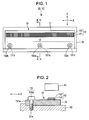
- Fig. 1 is a top view that schematically illustrates an example of the structure of the linear scale 10.
- Fig. 2 is a sectional view taken along the line II-II of Fig. 1 .
- Fig. 3 is an arrow view that illustrates the linear scale 10 viewed from the arrow direction III of Fig. 1 .
- the linear scale 10 is used for displacement measurement. Specifically, the linear scale 10 is used for a photoelectric reflective linear encoder. As illustrated in Fig. 1 , the linear scale 10 is provided with a scale table (scale board) 11, a graduation part 12, and an attachment part 13.
- the scale table 11 has the shape of a substantially rectangular parallelepiped.
- the direction of the long sides of the scale table 11 is referred to as the X direction.
- the direction of the short sides of the scale table 11 is hereinafter referred to as the Y direction.
- the X direction is the direction in which the linear scale 10 moves relative to a detector 40 at the time of measurement.
- the scale table 11 is made of low expansion ceramics. It is preferable that the low expansion ceramics should have a thermal expansion coefficient ⁇ of 0.01 to 0.04 ppm/K (parts per million per Kelvin).
- oxide ceramics that contains only solid solution crystal made of Li-Mg-Al-Fe-Si-O element can be used. More specifically, a preferred example of the low expansion ceramics is low expansion ceramics manufactured by Nippon Steel Materials Co.,Ltd.
- the low expansion ceramics may have the same crystal structure as ⁇ -Cordierite in addition to the solid solution to give a greater rigidity.
- the comparable rigidity of the low expansion ceramics is preferably 50 Gpa/g/cm 3 or greater.
- the graduation part 12 is fixed to the scale table 11 at a position relatively close to one edge of the scale table 11 viewed in the Y direction.
- the graduation part 12 extends in the X direction as illustrated in Fig. 3 (and Fig. 1 ).
- the detector 40 reads the graduation part 12 at the time of measurement.
- the graduation part 12 includes graduations 121, which are read at the time of measurement, and a substrate 122 on which the graduations 121 are formed.
- the graduations 121 are bonded to the upper surface of the scale table 11.
- the graduations 121 constitute a stripe pattern that includes a plurality of graduation lines arranged with a predetermined pitch in the X direction.
- the graduations 121 are amplitude grating that is used for detection by a detector that utilizes a tri-grating principle or phase grating that is used for detection by a detector that uses a diffraction optical system.
- the substrate 122 is provided on the upper surface of the graduations 121.
- the substrate 122 is made of a transparent material such as glass. Accordingly, a beam of light that is used for measurement can pass through the substrate 122.
- the substrate 122 has the shape of an elongated rectangle.
- the substrate 122 is elongated in the X direction.
- the attachment part 13 has a structure for fastening the scale table 11 to a base member 30.
- the attachment part 13 is provided relatively close to the other edge of the scale table 11 viewed in the Y direction.
- the attachment part 13 includes through holes 131a, 131b, and 131c and screws 132a, 132b, and 132c.
- the through holes 131a, 131b, and 131c are formed through the scale table 11.
- the through holes 131a, 131b, and 131c are formed relatively close to the other edge of the scale table 11 viewed in the Y direction.
- the through holes 131a, 131b, and 131c are aligned in the X direction.
- the through hole 131a is formed at the X-directional center of the scale table 11, that is, a halfway position in the X direction.
- the through holes 131b and 131c are formed near respective edges of the scale table 11 viewed in the X direction.
- the screws 132a, 132b, and 132c are fitted in threaded holes 31a, 31b, and 31c, which are formed in the base member 30, through the through holes 131a, 131b, and 131c, respectively.
- the graduations 121 are formed on the lower surface of the substrate 122.
- the lower surface of the graduations 121 is bonded to the upper surface of the scale table 11.
- An adhesive 50 for example, a silicone adhesive (KE44T, Manufactured by Shin-Etsu Chemical Co., Ltd.), is used for the attachment of the graduations 121 to the scale table 11.
- the adhesion strengthens the mechanical combination of the graduations 121 and the scale table 11.
- the scale table 11 is made of low expansion ceramics that is far less susceptible to aged deterioration in comparison with other material such as glass, almost no aged deterioration occurs in the graduation part 12, which is fixed securely to the scale table 11. For this reason, it is possible to perform measurement with a high degree of accuracy.
- the scale table 11 since the scale table 11 is directly fastened to the base member 30 by means of the attachment part 13 (which includes the through holes 131a, 131b, and 131c and the screws 132a, 132b, and 132c), it is not necessary to provide a holder or the like that holds the scale table 11. Therefore, the linear scale 10 according to the first comparative example has a simple structure and can be manufactured at low cost.
- the substrate 122 is provided on the upper surface of the graduations 121. Therefore, the linear scale 10 according to the first comparative example has an advantage that it is possible to protect the graduations 121 from physical shock by means of the substrate 122.
- Fig. 5 is a sectional view that schematically illustrates an example of the structure of the linear scale 10a according to the second comparative example, which is taken along the line V-V.
- Fig. 6 is an arrow view that illustrates the linear scale 10a viewed from the arrow direction VI.
- the same reference numerals are consistently used for the same components as those of the linear scale 10 according to the first comparative example so as to omit any redundant explanation.
- the linear scale 10a according to the second comparative example is different from the linear scale 10 according to the first comparative example in that, as illustrated in Figs. 5 and 6 , graduations 121a of a graduation part 12a are formed on the upper surface of a substrate 122a thereof.
- the linear scale 10a can be used for an optical-type reflective linear encoder like the first comparative example. Besides such application, the linear scale 10a may be used for a capacitance-type reflective linear encoder or an electromagnetic-induction reflective linear encoder.
- the graduations 121a of the linear scale 10a are amplitude grating that is used for detection by a detector that utilizes a tri-grating principle or phase grating that is used for detection by a detector that uses a diffraction optical system like the first comparative example.
- the graduations 121a may be a random pattern that is used for detection by a capacitance detector or an electromagnetic induction detector.
- the substrate 122a of the graduation part 12a is bonded to the upper surface of the scale table 11.
- the substrate 122a is a printed circuit board (PCB) that is made of, for example, ferrous metal, glass epoxy, or the like.
- a method for manufacturing the linear scale 10a according to the second comparative example is explained below.
- the graduations 121a are formed on the upper surface of the substrate 122a.
- the lower surface of the substrate 122a is bonded to the upper surface of the scale table 11 by means of the adhesive 50.
- the rigidity of the scale table 11 is far greater than that of the substrate 122a. For this reason, since the precision of the scale table 11 determines its mechanical precision, the linear scale 10a according to the second comparative example produces the same advantageous effects as those of the first comparative example. In addition, since the graduations 121a are formed on the upper surface of the substrate 122a opposite the bonding surface thereof, the linear scale 10a can be used for a capacitance-type reflective linear encoder or an electromagnetic-induction reflective linear encoder.
- Fig. 8 is a top view that schematically illustrates an example of the structure of the linear scale 10b.
- the same reference numerals are consistently used for the same components as those of the linear scale 10 according to the first comparative example and the linear scale 10a according to the second comparative example so as to omit any redundant explanation.
- the linear scale 10b As illustrated in Fig. 8 , the linear scale 10b according to the first embodiment of the invention has four slits 141, 142, 143, and 144 that are formed in the scale table 11.
- Each of two slits 141 and 142 formed in the scale table 11 is a straight slit that extends in the Y direction from one edge face closer to the attachment part 13 to a region near a halfway point in the Y direction. These two slits 141 and 142 extend in the neighborhood of the through hole 131a.
- the through hole 131a is formed between the slit 141 and the slit 142.
- Each of two slits 143 and 144 formed in the scale table 11 is an L-shaped slit that extends from the one edge face closer to the attachment part 13 in a bent slit pattern resembling a letter L.
- the slit 143 "encloses" the through hole 131b.
- the slit 144 encloses the through hole 131c.
- the linear scale 10b according to the first embodiment of the invention has the slits 141, 142, 143, and 144 formed in the scale table 11, even in a case where the scale table 11 changes in form due to linear expansion, the slits 141, 142, 143, and 144 can absorb deformation due to the change in form of the scale table 11 and thereby prevent the deformation from affecting the graduation part 12. Having the slits 141, 142, 143, and 144, the linear scale 10b according to the first embodiment of the invention makes it possible to perform measurement with a higher degree of accuracy in comparison with the first and second comparative examples.
- Fig. 9 is a top view that schematically illustrates an example of the structure of the linear scale 10c.
- the same reference numerals are consistently used for the same components as those of the linear scales 10, 10a, and 10b according to the first and the second comparative examples, and the first embodiment of the invention so as to omit any redundant explanation.
- the linear scale 10c according to the second embodiment of the invention has two straight slits 145 and 146 as a substitute for the two L-shaped slits 143 and 144 of the linear scale 10b according to the first embodiment of the invention.
- the straight slits 145 and 146 extend in the X direction from the respective X-directional edges toward a region near a halfway point of a scale table 11c.
- the two slits 145 and 146 separates, not completely but partially, the entire area of the scale table 11c into two areas, which are a first area AR1 and a second area AR2.
- the first area AR1 is located at one edge side of the scale table 11c viewed in the Y direction.
- the second area AR2 is located at the other edge side thereof.
- the linear scale 10c according to the second embodiment of the invention produces the following advantageous effect besides the foregoing advantageous effects. Even in a case where the base member 30 changes in form, the slits 145 and 146 can absorb deformation and thereby prevent the deformation from affecting the graduation part 12. Having the slits 145 and 146, the linear scale 10c according to the second embodiment of the invention makes it possible to perform measurement with a higher degree of accuracy in comparison with the first embodiment of the invention.
- Fig. 10 is a top view that schematically illustrates an example of the structure of the linear scale 10d.
- Fig. 11 is a sectional view taken along the line XI-XI of Fig. 10.
- Fig. 12 is an arrow view that illustrates the linear scale 10d viewed from the arrow direction XII-XII of Fig. 10 .
- the linear scale 10d according to the third comparative example is different from the linear scale according to the foregoing comparative examples and embodiments of the invention in that, as illustrated in Figs. 10, 11, and 12 , a graduation part 12d includes graduations 121d only.
- the linear scale 10d is used for, for example, a photoelectric reflective linear encoder.
- the linear scale 10d may be used for a capacitance-type reflective linear encoder or an electromagnetic-induction reflective linear encoder.
- the graduations 121d are formed directly on the upper surface of the scale table 11.
- the graduations 121d are amplitude grating that is used for detection by a detector that utilizes a tri-grating principle or phase grating that is used for detection by a detector that uses a diffraction optical system.
- the graduations 121d may be a random pattern that is used for detection by a capacitance detector or an electromagnetic induction detector.
- the linear scale 10d according to the third comparative example offers an advantage in that the graduations 121d are less likely to be affected by aged deterioration in comparison with the graduations 121, 121a formed on the substrate 122, 122a, which is made of, for example, glass, iron, or the like (the first comparative example, the second comparative example). That is, the linear scale 10d according to the third comparative example makes it possible to perform measurement with a higher degree of accuracy in comparison with the first and second comparative examples.
- Fig. 13 is a top view that schematically illustrates an example of the structure of the linear scale 10e.
- Fig. 14 is a sectional view taken along the line XIV-XIV of Fig. 13 .
- the same reference numerals are consistently used for the same components as those of the linear scales 10, 10a, 10b, 10c, and 10d according to the first, the second, and the third fourth comparative examples, and the first and second embodiments of the invention so as to omit any redundant explanation.
- an attachment part 13e includes through holes 131be and 131ce as a substitute for the through holes 131b and 131c of the first comparative example.
- the diameter of the through hole 131be, 131ce is larger than that of the through hole 131b, 131c.
- the attachment part 13e includes an elastic member 133b and a bush 134b inside the through hole 131be and further includes an elastic member 133c and a bush 134c inside the through hole 131ce.
- Each of the elastic members 133b and 133c is made of resin that has a predetermined modulus of elasticity.
- An example of the resin is silicon rubber.
- Each of the elastic members 133b and 133c has the shape of a ring. The elastic members 133b and 133c are fitted in the through holes 131be and 131ce, respectively.
- the bushes 134b and 134c are fitted in the elastic members 133b and 133c, respectively.
- Each of the bushes 134b and 134c has an upper part 134A and a lower part 134B.
- the upper part 134A has a first outside diameter.
- the lower part 134B has a second outside diameter.
- the first outside diameter of the upper part 134A is larger than the diameter of the through hole 131be, 131ce of the scale table 11.
- the second outside diameter of the lower part 134B is substantially equal to the inner diameter of the elastic member 133b, 133c.
- the screws 132b and 132c are fitted in the threaded holes 31b and 31c, which are formed in the base member 30, through the bushes 134b and 134c, respectively.
- the scale table 11 is fastened to the base member 30 by means of the screws 132b and 132c respectively through the through holes 131be and 131ce, the elastic members 133b and 133c, and the bushes 134b and 134c. Therefore, even in a case where the scale table 11 changes in form due to linear expansion, the elastic members 133b and 133c can absorb deformation due to the change in form of the scale table 11 and thereby prevent the deformation from affecting the graduation part 12.
- the linear scale 10e according to the fourth comparative example which is provided with the elastic members 133b and 133c and the bushes 134b and 134c, makes it possible to perform measurement with a higher degree of accuracy in comparison with the first comparative example.
Landscapes
- Physics & Mathematics (AREA)
- General Physics & Mathematics (AREA)
- Optical Transform (AREA)
- Transmission And Conversion Of Sensor Element Output (AREA)
Claims (5)
- Linearskala (10), die zur Verschiebungsmessung verwendet wird, umfassend:Ein Skalenbrett (11), das aus Keramik geringer Dehnung hergestellt ist;eine Teilstricheinheit (12), die an einer Oberseite des Skalenbretts (11) befestigt ist, wobei die Teilstricheinheit zur Zeit der Messung gelesen wird; undeine Befestigungseinheit (13), die ein Skalenbrett (11) an ein Basiselement (30) befestigt; dadurch gekennzeichnet, dassdas Skalenbrett (11) einen Schlitz (141, 142, 143, 144) aufweist, der nahe der Befestigungseinheit (13) gebildet ist.
- Linearskala (10) nach Anspruch 1, wobei die Keramik geringer Dehnung Oxidkeramik ist, die Mischkristall enthält, das aus irgendeinem Li-Mg-Al-Fe-Si-O Element hergestellt ist.
- Linearskala (10) nach Anspruch 1 oder Anspruch 2, wobei das Skalenbrett (11) einen ersten Bereich (AR1), der sich an einer Kantenseite des Skalenbretts (11) befindet und einen zweiten Bereich (AR2) aufweist, der sich an der anderen Kantenseite des Skalenbretts (11) befindet; die Teilstricheinheit (12) ist am ersten Bereich (AR1) bereitgestellt; die Befestigungseinheit (13) ist am zweiten Bereich (AR2) bereitgestellt; und der Schlitz (141, 142, 143, 144) ist zwischen dem ersten Bereich (AR1) und dem zweiten Bereich (AR2) gebildet.
- Linearskala (10) nach einem der vorhergehenden Ansprüche, wobei die Befestigungseinheit (13) ein Durchgangsloch (131a, 131b, 131c), das durch das Skalenbrett (11) hindurch gebildet ist, und eine Schraube (132a, 132b, 132c) einschließt, die in einem Gewindeloch (31 a, 31b, 31 c) durch das Durchgangsloch (131a, 131b, 131c) hindurch angebracht ist; und das Gewindeloch (31a, 31b, 31c) ist im Basiselement (30) gebildet.
- Linearskala (10) nach einem der vorhergehenden Ansprüche, wobei die Befestigungseinheit (13) ein Durchgangsloch (131a, 131b, 131c), das durch das Skalenbrett (11) gebildet ist, ein elastisches Element (133b), das die Form eines Rings hat und im Durchgangsloch (131a, 131b, 131 c) angebracht ist, eine Buchse (134b), die im elastischen Element (133b) angebracht ist, und eine Schraube (132a, 132b, 132c) einschließt, die in einem Gewindeloch (31 a, 31b, 31c) durch die Buchse (134b) hindurch angebracht ist; und das Gewindeloch (31a, 31b, 31c) ist im Basiselement (30) gebildet.
Applications Claiming Priority (1)
| Application Number | Priority Date | Filing Date | Title |
|---|---|---|---|
| JP2009071525A JP5162800B2 (ja) | 2009-03-24 | 2009-03-24 | リニアスケール |
Publications (3)
| Publication Number | Publication Date |
|---|---|
| EP2233893A2 EP2233893A2 (de) | 2010-09-29 |
| EP2233893A3 EP2233893A3 (de) | 2014-12-24 |
| EP2233893B1 true EP2233893B1 (de) | 2016-10-19 |
Family
ID=42421970
Family Applications (1)
| Application Number | Title | Priority Date | Filing Date |
|---|---|---|---|
| EP10157443.2A Not-in-force EP2233893B1 (de) | 2009-03-24 | 2010-03-23 | Linearskala |
Country Status (3)
| Country | Link |
|---|---|
| US (1) | US7934324B2 (de) |
| EP (1) | EP2233893B1 (de) |
| JP (1) | JP5162800B2 (de) |
Families Citing this family (10)
| Publication number | Priority date | Publication date | Assignee | Title |
|---|---|---|---|---|
| DE102009044917A1 (de) * | 2009-09-23 | 2011-04-07 | Dr. Johannes Heidenhain Gmbh | Längenmesseinrichtung |
| US8739424B2 (en) * | 2011-06-24 | 2014-06-03 | Mitutoyo Corporation | Structure for protecting scale graduations |
| JP2014224705A (ja) * | 2013-05-15 | 2014-12-04 | キヤノン株式会社 | スケール保持装置、およびエンコーダ |
| JP6215660B2 (ja) * | 2013-11-13 | 2017-10-18 | 株式会社ジェイテクト | 研削盤 |
| JP6355349B2 (ja) * | 2014-02-04 | 2018-07-11 | 株式会社ミツトヨ | リニアエンコーダ |
| DE102014218483B4 (de) * | 2014-09-15 | 2016-10-13 | Deckel Maho Pfronten Gmbh | Positionsmesseinrichtung zum Einsatz an einer Werkzeugmaschine |
| JP2016165785A (ja) * | 2015-03-10 | 2016-09-15 | 株式会社ディスコ | 可動装置および加工装置 |
| JP6738661B2 (ja) * | 2016-06-16 | 2020-08-12 | 株式会社ミツトヨ | 産業機械 |
| JP6895332B2 (ja) * | 2017-07-05 | 2021-06-30 | 株式会社ミツトヨ | リニアスケール |
| EP4560270A1 (de) | 2023-11-23 | 2025-05-28 | Etel S.A. | Skalenträger für eine codiererskala und linearer codierer mit solch einem skalenträger |
Family Cites Families (15)
| Publication number | Priority date | Publication date | Assignee | Title |
|---|---|---|---|---|
| DE3625795A1 (de) * | 1986-07-30 | 1988-02-04 | Heidenhain Gmbh Dr Johannes | Laengenmesseinrichtung |
| CH679334A5 (de) * | 1989-09-11 | 1992-01-31 | Weber Hans R | |
| DE4320728C2 (de) * | 1993-06-23 | 2001-08-02 | Heidenhain Gmbh Dr Johannes | Lagemeßeinrichtung |
| DE19821558B4 (de) * | 1997-08-08 | 2007-09-13 | Dr. Johannes Heidenhain Gmbh | Maßstab und Verfahren zur Herstellung eines Maßstabes sowie Positionsmeßeinrichtung |
| DE19854318A1 (de) * | 1998-11-25 | 2000-05-31 | Heidenhain Gmbh Dr Johannes | Längenmeßeinrichtung |
| JP4024600B2 (ja) * | 2002-06-25 | 2007-12-19 | 株式会社ミツトヨ | 枠多点固定タイプのユニット型直線変位測定装置、及び、その固定方法 |
| TWI310326B (en) * | 2005-10-11 | 2009-06-01 | Gsi Group Corp | Optical metrological scale and laser-based manufacturing method therefor |
| US7707739B2 (en) * | 2005-11-04 | 2010-05-04 | Dr. Johannes Heidenhain Gmbh | Method for attaching a scale to a carrier, a scale, and carrier having a scale |
| ES2535851T3 (es) * | 2005-11-04 | 2015-05-18 | Dr. Johannes Heidenhain Gmbh | Procedimiento para la fijación de una escala de medición en un soporte, escala de medición adaptada así como soporte con esta escala de medición |
| JP5108289B2 (ja) | 2005-12-06 | 2012-12-26 | 株式会社ミツトヨ | 変位測定装置用スケール |
| CN101416031A (zh) * | 2006-03-29 | 2009-04-22 | 约翰尼斯海登海恩博士股份有限公司 | 用于使刻度尺保持在载体上的方法以及具有载体和刻度尺的装置 |
| JP2007314363A (ja) * | 2006-05-24 | 2007-12-06 | Nippon Steel Materials Co Ltd | 低熱膨張セラミックス材料およびその製造方法 |
| JP2009047514A (ja) * | 2007-08-17 | 2009-03-05 | Sony Corp | 位置検出装置の取付構造 |
| US7971487B2 (en) * | 2008-05-02 | 2011-07-05 | Carlen Controls, Inc. | Linear position transducer with wireless read head |
| TW201003053A (en) * | 2008-07-10 | 2010-01-16 | Nikon Corp | Deformation measuring apparatus, exposure apparatus, jig for deformation measuring apparatus, position measuring method and device manufacturing method |
-
2009
- 2009-03-24 JP JP2009071525A patent/JP5162800B2/ja not_active Expired - Fee Related
-
2010
- 2010-03-23 US US12/729,565 patent/US7934324B2/en active Active
- 2010-03-23 EP EP10157443.2A patent/EP2233893B1/de not_active Not-in-force
Non-Patent Citations (1)
| Title |
|---|
| None * |
Also Published As
| Publication number | Publication date |
|---|---|
| JP5162800B2 (ja) | 2013-03-13 |
| US20100242295A1 (en) | 2010-09-30 |
| EP2233893A2 (de) | 2010-09-29 |
| EP2233893A3 (de) | 2014-12-24 |
| JP2010223767A (ja) | 2010-10-07 |
| US7934324B2 (en) | 2011-05-03 |
Similar Documents
| Publication | Publication Date | Title |
|---|---|---|
| EP2233893B1 (de) | Linearskala | |
| US7554340B2 (en) | Capacitive sensor | |
| EP2175280A1 (de) | Montiersystem für eine Torsionssuspension einer MEMS-Vorrichtung | |
| KR20040047684A (ko) | 가속도 센서 | |
| US8671752B2 (en) | Sensor system | |
| KR20080015500A (ko) | 각속도 센서 | |
| EP1407278B1 (de) | Beschleunigungsaufnehmer | |
| US5630283A (en) | Linear or angular encoder | |
| JP4230810B2 (ja) | 測長装置 | |
| US8257119B2 (en) | Systems and methods for affixing a silicon device to a support structure | |
| EP1634046B1 (de) | Drucksensor mit integrierter struktur | |
| US10788387B2 (en) | Component having a micromechanical sensor module | |
| US12270824B2 (en) | Sensor system, method for operating a sensor system | |
| US10209103B2 (en) | Linear encoder | |
| KR20020062795A (ko) | 가속도 센서 | |
| JP2004119624A (ja) | 回路基板 | |
| JP4401847B2 (ja) | 変位測定装置 | |
| RU2746763C1 (ru) | Микромеханический акселерометр | |
| RU2421736C1 (ru) | Акселерометр | |
| CN114485452B (zh) | 一种非热式光纤应变仪 | |
| US7997133B2 (en) | Temperature compensating sensor | |
| JP2006153516A (ja) | 加速度センサ | |
| JP2006153518A (ja) | 加速度センサ | |
| JPH05333051A (ja) | 半導体加速度センサ | |
| JP2006153515A (ja) | 加速度センサ |
Legal Events
| Date | Code | Title | Description |
|---|---|---|---|
| PUAI | Public reference made under article 153(3) epc to a published international application that has entered the european phase |
Free format text: ORIGINAL CODE: 0009012 |
|
| AK | Designated contracting states |
Kind code of ref document: A2 Designated state(s): AT BE BG CH CY CZ DE DK EE ES FI FR GB GR HR HU IE IS IT LI LT LU LV MC MK MT NL NO PL PT RO SE SI SK SM TR |
|
| AX | Request for extension of the european patent |
Extension state: AL BA ME RS |
|
| PUAL | Search report despatched |
Free format text: ORIGINAL CODE: 0009013 |
|
| AK | Designated contracting states |
Kind code of ref document: A3 Designated state(s): AT BE BG CH CY CZ DE DK EE ES FI FR GB GR HR HU IE IS IT LI LT LU LV MC MK MT NL NO PL PT RO SE SI SK SM TR |
|
| AX | Request for extension of the european patent |
Extension state: AL BA ME RS |
|
| RIC1 | Information provided on ipc code assigned before grant |
Ipc: G01D 5/347 20060101AFI20141117BHEP |
|
| 17P | Request for examination filed |
Effective date: 20150216 |
|
| RBV | Designated contracting states (corrected) |
Designated state(s): AT BE BG CH CY CZ DE DK EE ES FI FR GB GR HR HU IE IS IT LI LT LU LV MC MK MT NL NO PL PT RO SE SI SK SM TR |
|
| 17Q | First examination report despatched |
Effective date: 20160226 |
|
| GRAP | Despatch of communication of intention to grant a patent |
Free format text: ORIGINAL CODE: EPIDOSNIGR1 |
|
| INTG | Intention to grant announced |
Effective date: 20160801 |
|
| GRAS | Grant fee paid |
Free format text: ORIGINAL CODE: EPIDOSNIGR3 |
|
| GRAA | (expected) grant |
Free format text: ORIGINAL CODE: 0009210 |
|
| AK | Designated contracting states |
Kind code of ref document: B1 Designated state(s): AT BE BG CH CY CZ DE DK EE ES FI FR GB GR HR HU IE IS IT LI LT LU LV MC MK MT NL NO PL PT RO SE SI SK SM TR |
|
| REG | Reference to a national code |
Ref country code: GB Ref legal event code: FG4D |
|
| REG | Reference to a national code |
Ref country code: CH Ref legal event code: EP |
|
| REG | Reference to a national code |
Ref country code: AT Ref legal event code: REF Ref document number: 838736 Country of ref document: AT Kind code of ref document: T Effective date: 20161115 |
|
| REG | Reference to a national code |
Ref country code: IE Ref legal event code: FG4D |
|
| REG | Reference to a national code |
Ref country code: DE Ref legal event code: R096 Ref document number: 602010037259 Country of ref document: DE |
|
| REG | Reference to a national code |
Ref country code: NL Ref legal event code: MP Effective date: 20161019 |
|
| REG | Reference to a national code |
Ref country code: LT Ref legal event code: MG4D |
|
| PG25 | Lapsed in a contracting state [announced via postgrant information from national office to epo] |
Ref country code: LV Free format text: LAPSE BECAUSE OF FAILURE TO SUBMIT A TRANSLATION OF THE DESCRIPTION OR TO PAY THE FEE WITHIN THE PRESCRIBED TIME-LIMIT Effective date: 20161019 |
|
| REG | Reference to a national code |
Ref country code: AT Ref legal event code: MK05 Ref document number: 838736 Country of ref document: AT Kind code of ref document: T Effective date: 20161019 |
|
| PG25 | Lapsed in a contracting state [announced via postgrant information from national office to epo] |
Ref country code: LT Free format text: LAPSE BECAUSE OF FAILURE TO SUBMIT A TRANSLATION OF THE DESCRIPTION OR TO PAY THE FEE WITHIN THE PRESCRIBED TIME-LIMIT Effective date: 20161019 Ref country code: NO Free format text: LAPSE BECAUSE OF FAILURE TO SUBMIT A TRANSLATION OF THE DESCRIPTION OR TO PAY THE FEE WITHIN THE PRESCRIBED TIME-LIMIT Effective date: 20170119 Ref country code: SE Free format text: LAPSE BECAUSE OF FAILURE TO SUBMIT A TRANSLATION OF THE DESCRIPTION OR TO PAY THE FEE WITHIN THE PRESCRIBED TIME-LIMIT Effective date: 20161019 Ref country code: GR Free format text: LAPSE BECAUSE OF FAILURE TO SUBMIT A TRANSLATION OF THE DESCRIPTION OR TO PAY THE FEE WITHIN THE PRESCRIBED TIME-LIMIT Effective date: 20170120 |
|
| PG25 | Lapsed in a contracting state [announced via postgrant information from national office to epo] |
Ref country code: FI Free format text: LAPSE BECAUSE OF FAILURE TO SUBMIT A TRANSLATION OF THE DESCRIPTION OR TO PAY THE FEE WITHIN THE PRESCRIBED TIME-LIMIT Effective date: 20161019 Ref country code: IS Free format text: LAPSE BECAUSE OF FAILURE TO SUBMIT A TRANSLATION OF THE DESCRIPTION OR TO PAY THE FEE WITHIN THE PRESCRIBED TIME-LIMIT Effective date: 20170219 Ref country code: HR Free format text: LAPSE BECAUSE OF FAILURE TO SUBMIT A TRANSLATION OF THE DESCRIPTION OR TO PAY THE FEE WITHIN THE PRESCRIBED TIME-LIMIT Effective date: 20161019 Ref country code: NL Free format text: LAPSE BECAUSE OF FAILURE TO SUBMIT A TRANSLATION OF THE DESCRIPTION OR TO PAY THE FEE WITHIN THE PRESCRIBED TIME-LIMIT Effective date: 20161019 Ref country code: AT Free format text: LAPSE BECAUSE OF FAILURE TO SUBMIT A TRANSLATION OF THE DESCRIPTION OR TO PAY THE FEE WITHIN THE PRESCRIBED TIME-LIMIT Effective date: 20161019 Ref country code: BE Free format text: LAPSE BECAUSE OF FAILURE TO SUBMIT A TRANSLATION OF THE DESCRIPTION OR TO PAY THE FEE WITHIN THE PRESCRIBED TIME-LIMIT Effective date: 20161019 Ref country code: PT Free format text: LAPSE BECAUSE OF FAILURE TO SUBMIT A TRANSLATION OF THE DESCRIPTION OR TO PAY THE FEE WITHIN THE PRESCRIBED TIME-LIMIT Effective date: 20170220 Ref country code: PL Free format text: LAPSE BECAUSE OF FAILURE TO SUBMIT A TRANSLATION OF THE DESCRIPTION OR TO PAY THE FEE WITHIN THE PRESCRIBED TIME-LIMIT Effective date: 20161019 Ref country code: ES Free format text: LAPSE BECAUSE OF FAILURE TO SUBMIT A TRANSLATION OF THE DESCRIPTION OR TO PAY THE FEE WITHIN THE PRESCRIBED TIME-LIMIT Effective date: 20161019 |
|
| REG | Reference to a national code |
Ref country code: DE Ref legal event code: R097 Ref document number: 602010037259 Country of ref document: DE |
|
| PG25 | Lapsed in a contracting state [announced via postgrant information from national office to epo] |
Ref country code: RO Free format text: LAPSE BECAUSE OF FAILURE TO SUBMIT A TRANSLATION OF THE DESCRIPTION OR TO PAY THE FEE WITHIN THE PRESCRIBED TIME-LIMIT Effective date: 20161019 Ref country code: SK Free format text: LAPSE BECAUSE OF FAILURE TO SUBMIT A TRANSLATION OF THE DESCRIPTION OR TO PAY THE FEE WITHIN THE PRESCRIBED TIME-LIMIT Effective date: 20161019 Ref country code: DK Free format text: LAPSE BECAUSE OF FAILURE TO SUBMIT A TRANSLATION OF THE DESCRIPTION OR TO PAY THE FEE WITHIN THE PRESCRIBED TIME-LIMIT Effective date: 20161019 Ref country code: EE Free format text: LAPSE BECAUSE OF FAILURE TO SUBMIT A TRANSLATION OF THE DESCRIPTION OR TO PAY THE FEE WITHIN THE PRESCRIBED TIME-LIMIT Effective date: 20161019 Ref country code: CZ Free format text: LAPSE BECAUSE OF FAILURE TO SUBMIT A TRANSLATION OF THE DESCRIPTION OR TO PAY THE FEE WITHIN THE PRESCRIBED TIME-LIMIT Effective date: 20161019 |
|
| PLBE | No opposition filed within time limit |
Free format text: ORIGINAL CODE: 0009261 |
|
| STAA | Information on the status of an ep patent application or granted ep patent |
Free format text: STATUS: NO OPPOSITION FILED WITHIN TIME LIMIT |
|
| PG25 | Lapsed in a contracting state [announced via postgrant information from national office to epo] |
Ref country code: IT Free format text: LAPSE BECAUSE OF FAILURE TO SUBMIT A TRANSLATION OF THE DESCRIPTION OR TO PAY THE FEE WITHIN THE PRESCRIBED TIME-LIMIT Effective date: 20161019 Ref country code: SM Free format text: LAPSE BECAUSE OF FAILURE TO SUBMIT A TRANSLATION OF THE DESCRIPTION OR TO PAY THE FEE WITHIN THE PRESCRIBED TIME-LIMIT Effective date: 20161019 Ref country code: BG Free format text: LAPSE BECAUSE OF FAILURE TO SUBMIT A TRANSLATION OF THE DESCRIPTION OR TO PAY THE FEE WITHIN THE PRESCRIBED TIME-LIMIT Effective date: 20170119 |
|
| 26N | No opposition filed |
Effective date: 20170720 |
|
| REG | Reference to a national code |
Ref country code: CH Ref legal event code: PL |
|
| PG25 | Lapsed in a contracting state [announced via postgrant information from national office to epo] |
Ref country code: SI Free format text: LAPSE BECAUSE OF FAILURE TO SUBMIT A TRANSLATION OF THE DESCRIPTION OR TO PAY THE FEE WITHIN THE PRESCRIBED TIME-LIMIT Effective date: 20161019 Ref country code: MC Free format text: LAPSE BECAUSE OF FAILURE TO SUBMIT A TRANSLATION OF THE DESCRIPTION OR TO PAY THE FEE WITHIN THE PRESCRIBED TIME-LIMIT Effective date: 20161019 |
|
| REG | Reference to a national code |
Ref country code: IE Ref legal event code: MM4A |
|
| REG | Reference to a national code |
Ref country code: FR Ref legal event code: ST Effective date: 20171130 |
|
| PG25 | Lapsed in a contracting state [announced via postgrant information from national office to epo] |
Ref country code: FR Free format text: LAPSE BECAUSE OF NON-PAYMENT OF DUE FEES Effective date: 20170331 Ref country code: LU Free format text: LAPSE BECAUSE OF NON-PAYMENT OF DUE FEES Effective date: 20170323 |
|
| PG25 | Lapsed in a contracting state [announced via postgrant information from national office to epo] |
Ref country code: IE Free format text: LAPSE BECAUSE OF NON-PAYMENT OF DUE FEES Effective date: 20170323 Ref country code: LI Free format text: LAPSE BECAUSE OF NON-PAYMENT OF DUE FEES Effective date: 20170331 Ref country code: CH Free format text: LAPSE BECAUSE OF NON-PAYMENT OF DUE FEES Effective date: 20170331 |
|
| PG25 | Lapsed in a contracting state [announced via postgrant information from national office to epo] |
Ref country code: MT Free format text: LAPSE BECAUSE OF NON-PAYMENT OF DUE FEES Effective date: 20170323 |
|
| PG25 | Lapsed in a contracting state [announced via postgrant information from national office to epo] |
Ref country code: HU Free format text: LAPSE BECAUSE OF FAILURE TO SUBMIT A TRANSLATION OF THE DESCRIPTION OR TO PAY THE FEE WITHIN THE PRESCRIBED TIME-LIMIT; INVALID AB INITIO Effective date: 20100323 |
|
| PG25 | Lapsed in a contracting state [announced via postgrant information from national office to epo] |
Ref country code: CY Free format text: LAPSE BECAUSE OF NON-PAYMENT OF DUE FEES Effective date: 20161019 |
|
| PG25 | Lapsed in a contracting state [announced via postgrant information from national office to epo] |
Ref country code: MK Free format text: LAPSE BECAUSE OF FAILURE TO SUBMIT A TRANSLATION OF THE DESCRIPTION OR TO PAY THE FEE WITHIN THE PRESCRIBED TIME-LIMIT Effective date: 20161019 |
|
| PG25 | Lapsed in a contracting state [announced via postgrant information from national office to epo] |
Ref country code: TR Free format text: LAPSE BECAUSE OF FAILURE TO SUBMIT A TRANSLATION OF THE DESCRIPTION OR TO PAY THE FEE WITHIN THE PRESCRIBED TIME-LIMIT Effective date: 20161019 |
|
| PGFP | Annual fee paid to national office [announced via postgrant information from national office to epo] |
Ref country code: GB Payment date: 20230321 Year of fee payment: 14 Ref country code: DE Payment date: 20220620 Year of fee payment: 14 |
|
| REG | Reference to a national code |
Ref country code: DE Ref legal event code: R119 Ref document number: 602010037259 Country of ref document: DE |
|
| GBPC | Gb: european patent ceased through non-payment of renewal fee |
Effective date: 20240323 |
|
| PG25 | Lapsed in a contracting state [announced via postgrant information from national office to epo] |
Ref country code: DE Free format text: LAPSE BECAUSE OF NON-PAYMENT OF DUE FEES Effective date: 20241001 |
|
| PG25 | Lapsed in a contracting state [announced via postgrant information from national office to epo] |
Ref country code: GB Free format text: LAPSE BECAUSE OF NON-PAYMENT OF DUE FEES Effective date: 20240323 |
|
| PG25 | Lapsed in a contracting state [announced via postgrant information from national office to epo] |
Ref country code: GB Free format text: LAPSE BECAUSE OF NON-PAYMENT OF DUE FEES Effective date: 20240323 Ref country code: DE Free format text: LAPSE BECAUSE OF NON-PAYMENT OF DUE FEES Effective date: 20241001 |