EP2228256B1 - Tiertransporter - Google Patents
Tiertransporter Download PDFInfo
- Publication number
- EP2228256B1 EP2228256B1 EP10156386.4A EP10156386A EP2228256B1 EP 2228256 B1 EP2228256 B1 EP 2228256B1 EP 10156386 A EP10156386 A EP 10156386A EP 2228256 B1 EP2228256 B1 EP 2228256B1
- Authority
- EP
- European Patent Office
- Prior art keywords
- mounting
- transporter
- animal
- guide
- tarpaulin
- Prior art date
- Legal status (The legal status is an assumption and is not a legal conclusion. Google has not performed a legal analysis and makes no representation as to the accuracy of the status listed.)
- Active
Links
Images


Classifications
-
- B—PERFORMING OPERATIONS; TRANSPORTING
- B60—VEHICLES IN GENERAL
- B60P—VEHICLES ADAPTED FOR LOAD TRANSPORTATION OR TO TRANSPORT, TO CARRY, OR TO COMPRISE SPECIAL LOADS OR OBJECTS
- B60P3/00—Vehicles adapted to transport, to carry or to comprise special loads or objects
- B60P3/04—Vehicles adapted to transport, to carry or to comprise special loads or objects for transporting animals
-
- A—HUMAN NECESSITIES
- A01—AGRICULTURE; FORESTRY; ANIMAL HUSBANDRY; HUNTING; TRAPPING; FISHING
- A01K—ANIMAL HUSBANDRY; AVICULTURE; APICULTURE; PISCICULTURE; FISHING; REARING OR BREEDING ANIMALS, NOT OTHERWISE PROVIDED FOR; NEW BREEDS OF ANIMALS
- A01K1/00—Housing animals; Equipment therefor
- A01K1/04—Tethering-poles or the like
-
- B—PERFORMING OPERATIONS; TRANSPORTING
- B60—VEHICLES IN GENERAL
- B60P—VEHICLES ADAPTED FOR LOAD TRANSPORTATION OR TO TRANSPORT, TO CARRY, OR TO COMPRISE SPECIAL LOADS OR OBJECTS
- B60P7/00—Securing or covering of load on vehicles
- B60P7/06—Securing of load
- B60P7/135—Securing or supporting by load bracing means
- B60P7/15—Securing or supporting by load bracing means the load bracing means comprising a movable bar
Definitions
- the invention relates to a holder of a speaker bar for an animal transporter, in particular in a horse transporter. Furthermore, the invention relates to a speaker bar, a support system for a speaker bar and an animal transporter, in particular a horse transporter.
- Box poles for animal transporters are for example from the DE 20 2006 010 385 U1 known. Such box poles are generally mounted transversely to the direction of travel of the animal carrier, in particular the horse transporter, for example, to limit a horse box or to prevent an animal located on the animal transporter from climbing down the animal transporter. The pit poles serve to keep the animal on the animal transporter.
- box bars may be made of a hard material such as a metal. It is desirable to protect the animal, in particular horse, to be transported in an animal transport vehicle from pressure loads and from risk of injury. Pressure loads arise, for example, in the chest area of the horse, when this bumps against a speaker bar.
- Such box poles are usually releasably attached to a holder for the speaker bar.
- a speaker bar For example, one end of a speaker bar is fixed in a first holder and the other end of a speaker bar is mounted in a second holder in accordance with a holding mechanism of the speaker bar.
- the two brackets are often located inside an animal transporter, particularly a horse transporter, and the box bar is attached to these brackets to confine a box, such as a horse box.
- Another or alternative object is to increase the flexibility of an animal carrier, in particular a horse transporter.
- a holder of an attached at one end of the box bar for an animal transporter, in particular a horse transporter provided.
- the holder has a guide of the other end of the speaker bar, the other end engages the guide.
- the guide connects a start portion for receiving the other end to an end portion for locking the other end. Between the starting portion and the end portion, the guide forms a stop for preventing accidental detachment of the other end from the end portion.
- the holder may for example be attached to an animal transporter, in particular to a horse transporter.
- rivets are suitable for fastening the holder.
- the other end of the speaker bar is bolt-shaped educated.
- the guide can be, for example, a recess in a plate, preferably a metal plate, which preferably has a narrow, oblong shape and describes a path around a tongue.
- the tongue then forms the stop.
- the starting area or entrance area of the guide serves to receive the other end, for example the bolt-shaped end of a box bar and to guide it to an end area.
- the end portion of the guide then defines the end seat or end position of the other end of the speaker bar.
- the other end of the speaker bar may be formed, for example, as a pin or a bolt.
- the formation of the stop between the starting region and the end region of the guide can mean, for example, that the stop is formed on or on the path which the guide describes.
- the stop can be used as a stop, a portion of a wall that defines the guide at least partially defined.
- the holder has a plurality of the guides, preferably three guides, which are arranged side by side in a first plane.
- the holder has a plurality of the guides, preferably three guides, which are arranged one above the other.
- Placing the plurality of guides side by side also means that the end portions of the guides are juxtaposed, resulting in different end positions of the other end of a speaker bar when inserted into another adjacent guide.
- the size of a limited with such a speaker bar box can thus be changed.
- three different box sizes are well suited for horse transporters.
- a desired dimensional variability of the box can be determined. For example, the box can only be adjusted in height if the end regions of the guides are arranged vertically one above the other on an animal transporter. For example, the box can only be adjusted in length if the end regions of the guides are arranged horizontally next to one another on an animal transporter.
- the holder is arranged with a plurality of guides on an animal transporter such that boxes of different height and length can be formed.
- the end portions of the guides of the holder on an inner side wall of the animal transporter different heights from the ground and arranged side by side in a horizontal direction.
- the guide is at least partially arcuate.
- An arcuate design of the guide results in a simple sliding of the other end of a speaker bar through the guide. Unintentional hooking of the other end in the guide is thus avoided or at least reduced.
- the holder has a first plane, in which the at least one guide is arranged, and a second plane, in which fastening means for fastening the holder, for example on an animal transporter, in particular on a horse transporter, are arranged, wherein the first Level and the second level are parallel and spaced from each other.
- the second level for example, has holes with which the holder can be attached, for example, to the inside of an animal carrier.
- the second level with the at least one guide is offset from this mounting plane so that a cavity can form between the wall of an animal carrier and the first level.
- a part of the other end of a box bar or a part of a bolt can be received by this cavity or in the space between the first level and the second level.
- the object is also achieved with a box bar for use in an animal transporter, in particular horse transporter.
- the box bar has an end for hanging on an animal carrier and the other end for insertion into a guide of a holder according to the invention.
- Hooking also provides releasable attachment.
- the one end of the box bar preferably has a U-shaped configuration with the U having unequal length legs. This U-shaped end can be plugged, for example, for attachment through a ring to an animal transporter.
- the other end is designed to allow movements of the other end along the guide and movements of the other End to prevent in the longitudinal direction of the speaker bar.
- the position of the speaker bar is better defined and accidental slippage is prevented. This is achieved, for example, in that at the other end of the box bar a section has a smaller cross-section than the adjacent sections, or in that the other end has a taper.
- the object is also achieved with a holder system for a box bar for use in an animal transporter, in particular in a horse transporter.
- the mounting system includes a bracket according to the invention and a second bracket for receiving one end of the speaker bar, the bracket system being adapted to permit release of the other end of the speaker bar from the second bracket only when the other end is disengaged.
- the second bracket is generally opposite the first bracket. If the first holder has a plurality of guides, then the second holder also has a plurality of holder devices, for example rings or eyelets, which respectively lie opposite the end position of the corresponding guide.
- the wall of the animal transporter is preferably a lateral outer wall of the animal transporter and / or an inner wall of the animal transporter, in particular an inner partition of the animal transporter, which separates two areas of the interior of the animal carrier, for example, to transport two horses separately in the animal transporter.
- the wall of the animal carrier is an outer wall
- the first surface of the outer wall is preferably the inner surface of the outer wall
- the second surface of the outer wall is preferably the outer surface of the outer wall.
- the holder for the speaker bar can be detached from the inner wall such that the holder falls within the animal carrier on the ground by the fastening means outside the animal carrier on the outer surface of the outer wall of the animal carrier is released.
- the at least one fastening means preferably has a screw, in particular an eyebolt.
- An eyebolt can be easily turned by, for example, a handle, such as a broom handle, passed through the eyebolt and then the eyebolt is rotated by means of the stem. This allows a quick release of the fastener, even if the bracket is firmly screwed.
- the support system has a receptacle attachable to the first surface of the wall for receiving a first end of the support as a first attachment means and a second attachment means for securing a second end of the support, wherein when the support is attached to the first surface of the wall is fixed, the second attachment means on the second surface is detachable, so that the holder can be removed from the receptacle to release the holder from the first surface of the wall.
- the second fastening means is preferably a screw, in particular an eyebolt. By loosening the second fastener, the bracket can be quickly and easily removed from the wall. It is therefore only necessary to release the second fastening means, in particular the screw, in order to remove the holder from the wall.
- the first surface is an inner surface of an outer wall of an animal carrier
- the second surface is the outer surface of this side wall.
- the receptacle preferably has a Anbindering. This makes it possible to attach animals, especially horses, to the recording.
- the recording thus fulfills at least two functions, on the one hand the holding and holding of the holder and on the other hand holding an animal when it has been connected by means of the Anbinderings to the recording.
- the object is also achieved with an animal transporter, in particular horse transporter, with a holder according to the invention or with a mounting system according to the invention.
- the object is also achieved with an animal transporter, in particular horse transporter, with a holder according to the invention, which is arranged on the animal transporter such that adjacent end regions are of different heights.
- the height here denotes the distance from the ground on which the transporter stands, or from a bottom plate of the transporter to the corresponding end region of a guide.
- the object is also achieved with an animal transporter, in particular horse transporter, with a speaker bar according to the invention.
- a retrofittable padding for padding a box bar for use in an animal transporter, especially in a horse transporter, may be provided.
- the retrofittable padding has a tubular shape and is adapted to receive the box bar and to be non-sliply connected to the box bar.
- the padding of non-padded pit poles as well as padded pit poles can be improved.
- the padding has a tubular shape, which means that the padding has a through hole through which the speaker bar can be slid. Once the padding has been pushed onto the speaker bar, it is connected to the speaker bar without slipping.
- the retrofitting allows a subsequent improvement of the padding, which also means that already existing upholstery can be subsequently improved with the retrofittable upholstery according to the invention on pit poles, d. H. the upholstery property is increased.
- a suitable retrofittable padding can be selected depending on the animal to be transported.
- the upholstery effect is improved by the retrofittable upholstery, but on the other hand, the size of the box in which an animal resides is also changed by a box bar with the retrofittable upholstery and thus adapted to the size of the corresponding animal.
- the non-slip connection between the retrofittable padding and the box bar means that after the padding is pulled onto the box bar, slippage occurs longitudinally of the bar as well as radially around the bar during normal use the upholstery is no longer possible. However, it is possible to remove the padding from the speaker bar with increased force.
- the retrofittable padding on stretchable material or consists of stretchable material.
- stretchable material is well suited for creating the non-slip connection between the padding and the box bar, because if the hole in the padding has a smaller diameter than the box bar, the retrofittable padding will stretch and rise as it is pulled up onto the box bar can press the box bar.
- slippage of the padding relative to the rod in the longitudinal direction or in the radial direction is made difficult or prevented.
- Stretchable material is particularly suitable for being able to adapt well to the outer structure of a speaker bar. Although this may be smooth, but for example, a corrugated or grooved structure may be present.
- the inside of the retrofittable padding on non-slip material The inside is the inside of the hole that extends through the retrofittable padding.
- a non-slip material may for example be a rubber-like material if the speaker bar has a metal-like material on the upper side, that is to say on the contact surface.
- the choice of material on the inside of the padding is therefore to match accordingly to the material of the outside of the speaker bar.
- a self-adhesive material can be used on the inside of the padding, so that not only a non-slip, but solid compound, d. H. non-detachable connection with which the speaker bar can be received.
- the padding may consist entirely of the non-slip material, but on the other hand, the padding on the inside may also be coated with a corresponding material.
- the choice of the appropriate configuration of the padding depends on the desired slip resistance between the retrofittable padding and the retrofitted speaker bar.
- the retrofittable padding on a soft elastic foam consists of a soft elastic foam.
- the soft-elastic foam preferably has molding densities in the range of 250 to 700 kg per m 3 (kg / m 3 ) and Shore A hardness of 25 to 70.
- a soft elastic foam part comprises a polyol component and an isocyanate component, for example in a mixing ratio of 100: 48.
- the polyol component is then a mixture of polyols, activators, stabilizers and, if appropriate, dyes.
- the isocyanate component is a preparation of diphenylmethane diisocyanate (MDI).
- MDI diphenylmethane diisocyanate
- a foam component consisting of this foam generally has different properties in the interior and on the skin Properties on. The following value ranges are preferred in the interior, ie the foam:
- the apparent density is between 172 and 430 kg / m 3 according to DIN 53420.
- the tensile strength is between 48 and 125 N / mm 2 according to DIN 53571.
- the elongation is between 110 and 145%. according to the test specification DIN 53571.
- the tear strength is in the range of 17.1 to 32 N / mm according to the test specification DIN 535
- the tensile strength is preferably 6.5 to 7.6 N / mm 2 according to the test specification DIN 53504.
- the elongation is preferably in the range of 145 to 175% according to the test specification DIN 53504.
- the tear propagation resistance is preferably in the range from 3.5 to 6 N / mm according to the test specification DIN 53515.
- Such a foam is available, for example, under the term "dipointegral" from Schaffer.
- the retrofittable padding on the outside of the padding on a protective cover may preferably consist of a very soft, for example hand flattering, material.
- the protective cover can serve on the one hand to make the outer contact of the pad even softer and also to protect the cushion core from damage, such as cracks.
- the upholstery may be adapted to be mounted on box poles of one or more different types.
- the padding can be adapted to be reared later on already known box poles.
- box poles the outside have a pin, can be provided in a preferred embodiment of the padding with this upholstery later.
- the animal transporter preferably has an opening, in particular a rear upper opening, which can be covered by means of a tarpaulin.
- an impermeable tarpaulin for covering the rear upper opening of an animal carrier, wherein the tarpaulin can be rolled up so that the opening is substantially released, or the tarpaulin can be rolled down so that the opening is covered by the tarpaulin.
- the rear upper opening can therefore be substantially only completely covered by the tarpaulin or substantially completely released from the tarpaulin. It is not possible to provide different degrees of coverage of the opening in order to set desired wind conditions and temperatures, especially while driving within the animal carrier.
- a tarpaulin for covering an opening, in particular a rear upper opening, of an animal transporter, in particular of a horse transporter may be provided, the tarpaulin having an air-permeable mesh area, an impermeable area and a cover tarpaulin for covering the air-permeable net area.
- the tarpaulin has an air-permeable mesh area and an impermeable area, and since the tarpaulin also has a tarpaulin for covering the air-permeable net area, different wind conditions and temperatures can be realized within the animal carrier, in particular while driving.
- the tarpaulin may be completely pulled down and the cover may cover the air-permeable mesh area. In this case, the opening is maximally closed.
- the tarpaulin could be completely rolled up so that it does not cover the opening. In this case, there is a minimum or nonexistent coverage of the opening.
- the tarpaulin can be completely pulled down and the tarpaulin can release the air-permeable mesh area.
- the tarpaulin is a tarpaulin lift.
- a tarpaulin lift is in particular a tarpaulin which can be rolled up automatically, in particular by means of leaf springs.
- a tarpaulin lift will be described in more detail below.
- the tarpaulin and / or the tarpaulin are adapted so that the tarpaulin is changeable between a first state and a second state, wherein in the first state, a larger part of the network area is covered, in particular the network area is completely covered, and in the second Condition a smaller part of the network area is covered or the network area is not covered.
- the tarpaulin and / or the tarpaulin has a holding means for holding the tarpaulin in the first state and / or in the second state.
- the holding means is preferably a hook and loop fastener.
- An animal transporter in particular a horse transporter, having an opening, in particular a rear upper opening, may have a cover according to the invention for covering the opening.
- An animal transporter usually has a bottom plate with usually specially elaborated openings, which can accommodate a rod, in particular a tube, a partition wall for securing the partition in the animal transporter. This requires a costly processing of the bottom plate.
- the partition usually can not be easily detached again from the bottom plate. It can therefore be provided a fastener, a rod, a partition wall and an animal transporter, which make it possible to easily without attaching the bottom plate a rod, in particular a rod of a partition wall and thus the partition itself to attach to the bottom plate and this, if it is desired to easily release again from the bottom plate.
- a fastening element for fastening a rod in particular a partition, may be provided on a floor element of an animal transporter, wherein the fastening element has a floor connection area for connecting the floor Fastener having the bottom element and a rod connecting portion for connecting the fastener with the rod.
- the fastener can be easily connected to the floor member, after which only the rod, which is in particular a rod of a partition, is to be connected to the rod connecting portion of the fastener.
- the floor connecting portion may be adapted to easily connect to the floor member, and regardless of this, the rod connecting portion may be formed so that the rod and thus, in particular, a partition are easily connected to the fastener and also easily released from the fastener can.
- the floor connecting portion has at least two connecting holes for passing connecting means for connecting the fixing member to the floor member.
- the fastening element to be connected to the floor element by means of a simple screw connection.
- the bottom element preferably has two corresponding openings, in particular boreholes, in order to screw the fastening element to the floor element.
- the rod connection portion has a locking aperture for receiving a locking element of the rod for establishing a locking connection.
- the partition wall may, for example, comprise a bent bar or a plurality of bars to be connected to the floor element. At least at a connection point, a rod of the partition is connected by means of the fastening element with the bottom element. Other joints between a rod of the partition wall and the floor member may also be connected to the floor member by means of the fastener or in some other way. For example, if there are two such connection points, the first connection point could be generated by means of the fastening element by the bar of the partition, that is, the locking element of the rod is guided in the unlocked state in the locking opening of the fastener.
- the partition wall is preferably rotated so that it is arranged in the longitudinal direction of the animal transporter, whereby by this rotational movement, the rod is locked with the fastening element.
- this connection can be made in another way, for example by putting the rod into a corresponding opening in the bottom element, screwing it down, etc.
- the locking element of the rod can also be referred to as a securing pin.
- the fastening element has a bottom side, which in the fastened state faces the floor element, and a rod side, which in the fastened state essentially faces the bar, the bar side being rounded. The rounding can prevent injury to animals to the fastener.
- the fastening element is designed so that it forms a cavity with the bottom element in the state connected to the bottom element, into which the locking element can be inserted through the locking opening for fastening the rod, wherein the fastening element has cleaning openings, the Allow cleaning of the cavity.
- the locking hole has a circular area and a substantially rectangular area adjoining the circular area, with a line from the center of the circular area to the center of the rectangular portion encloses a non-zero angle with a line connecting the two connecting holes.
- a rod in particular a partition within an animal carrier, may be provided, wherein the rod has a locking element for insertion into a locking opening of the fastening element, for establishing a locking connection between the rod and the fastening element.
- a partition for an animal transporter with the rod and an animal transporter can be provided with the fastener.
- the animal transporter preferably further comprises the rod and / or the partition wall.
- An animal transport vehicle may have a known opening window in which, during the journey, driving wind penetrates through the opening window into the interior of the animal carrier when the opening window is open. This creates wind and ventilation conditions in the animal transporter, which can, for example, lead to the animals becoming too cold, causing diseases, for example.
- the animal transporter in particular the horse trailer, may have an opening window for covering an opening, in particular a front lateral opening, of the animal transporter, the opening having a first side facing a direction of travel, a second side facing away from the direction of travel, and a third side bounding the opening below, the opening window being movably connected to the first side by means of window fixing means.
- the opening window is movably connected to the first side by means of window fastening means, the side of the opening window facing the direction of travel will not be opened even when the opening window is opened, so that less airstream or even no airflow will pass from the front through the opening into the interior of the animal carrier can.
- the window fixing means are rubber members connected to the opening and the opening window.
- the rubber elements are cylindrical, wherein at opposite ends of a rubber element connecting elements for connecting, in particular screw elements for screwing, the rubber element with the opening and the Ausstellpper available.
- the screw elements do not run continuously within the rubber element, that is, a central cross section of the cylindrically shaped rubber element has only rubber.
- the rubber member may be waisted, that is, the diameter of the rubber member is halfway lower than at the ends of the rubber member.
- These rubber elements act as hinges and allow a simple hinge connection between the opening window and the opening, by connecting one end of the respective rubber element to the opening window and another end of the respective rubber element to the edge of the opening.
- the Austellhot has a handle for opening and closing the Ausstellromes, wherein the handle is connected by means of a leaf spring with the opening.
- the leaf spring is preferably connected to the handle and the opening, that in the closed state, the leaf spring holds the hinged window in the closed state and that when opening the Ausstellppers first a force in Ausstellcardi must be exercised, wherein after a dead center has been exceeded, the Leaf spring endeavors to open the hinged window and the leaf spring holds the hinged window in the open position.
- the handle can be connected by means of one or more leaf springs with the opening.
- the opening is provided with a window frame, wherein the Ausstellrome is connected for connecting to the opening with the window frame. That is, preferably, the opening window is not directly connected to the opening, but indirectly by means of the window frame, which is connected to the opening. This means, in particular, that the opening window is connected by means of the rubber elements with the window frame, which in turn is connected to the opening to connect the opening window indirectly with the opening, in particular with the first side of the opening.
- the opening window is connected directly or indirectly by means of the window frame by the rubber elements exclusively on the first side, wherein a further connection of the Ausstellromes with the third side of the Opening is produced by the handle and the leaf spring, wherein the leaf spring is preferably connected to the window frame to connect the handle by means of the leaf spring with the opening.
- the handle is preferably mounted centrally on a lower side of the Ausstellromes, which faces the third side of the opening.
- the handle is preferably fastened to the interior of the opening window.
- the invention further relates to a hinged window with a window frame, wherein the hinged window is movably connected to the window frame by rubber elements 507.
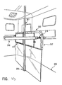
- FIG. 1 shows a holder 20 with a first guide 21, a second guide 22 and a third guide 23.
- the second guide 22 leads around a tongue which forms a stop 24 to an end portion 25 of the second guide 22.
- the first guide 21 and the third guide 23 have the same shape as the second guide 22 and accordingly also each have a stopper 24 and an end portion 25.
- a box bar 40 has a first end 41 (the other end) located in the end portion of the first guide 21 is located.
- the holder 20 also has a first plane 26 and a second plane 27.
- the first plane 26 has the guides 21, 22 and 23 and is offset from the second plane 27, d. H. between the first plane 26 and the second plane 27 or the wall of a horse transporter, a cavity 29 is formed. This serves to receive a rear part 42 of the first end 41 of the box bar 40.
- the guides 21, 22 and 23 are predominantly arcuate, so a good sliding of the first end 41 through the guides 21, 22 or 23 is possible and tilting of the first end 41 of the speaker bar 40 is avoided as possible.
- the stop 24 prevents the box bar 40 from slipping out of the corresponding guide or out of the holder. In such a stress, the box bar 40 could hit at most against the stop 24, but not slip out of the respective guide 21, 22 or 23.
- FIG. 2 shows the box bar 40 with the first end 41 before the first end 41 is inserted into the third guide 23 of the holder 20.
- the first end 41 of the box bar 40 is formed bolt-shaped and has a taper 43.
- the bolt has a rear part 42, which lies behind the taper 43 and a front part 44, which lies in front of the taper 43, on.
- the rear part 42 is in the cavity 29 between the first level 26 and second level 27 (see also FIG. 1 ).
- the taper 43 is in the guide 23 and the front part 44 of the first end 41 is located in front of the first plane 26.
- the box bar 40 when it is in the guide 23, can not be moved in the direction of the longitudinal axis of the box bar 40, but only along the guide 23.
- the box bar 40 For receiving the rear part 42 in the cavity 29 is at an initial portion 30th the third guide 23 (and also the first guide 21 and the second guide 22) a widening provided so that the rear part 42 can be received in the cavity 29.
- FIG. 3 shows a second bracket 60 having a first bracket ring 61, a second bracket ring 62 and a third bracket ring 63.
- the second bracket 60 is attached to a horse transporter 70 (see FIG FIG. 4 ) attached.
- a second end 45 (one end) of the speaker bar 40 is substantially U-shaped, with the U having different lengths of leg so that the second end 45 is hooked into the first ring 61 and second ring 62 or third ring 63, respectively can be.
- the first ring 61 is preferably opposite the end portion of the first guide 21, the second ring 62 is preferably opposite the end portion of the second guide 22, and the third ring 63 is preferably opposite the end portion of the third guide 23 FIG.
- the box bar 40 hangs down so that the box is in an open condition. Moving the first end 41 of the speaker bar 40 to the first guide 21 of the holder 20 would not release the connection of the second end 45 with the first ring 61. For this purpose, a movement of the rod 40 in the longitudinal direction upwards would be required.
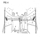
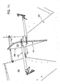
- FIG. 4 shows the interior of a horse transporter with a mounting system according to the invention.
- the box bar 40 is hooked with its second end 45 in the first ring 61 of the second holder 60.
- the first end 41 is located in the end position or in the end region 25 of the first guide 21.
- the second end 45 can not be released from the first ring 61, without first the first end 41 from the holder 20 and from the first guide 21 to solve.
- An unintentional slipping out of the first end 41 of the guide 21 is prevented by an existing stop 24 on the bracket 20.
- the size of the box can be changed by hanging the box bar 40 in another ring or guide. Depending on the inclination of the brackets and depending on the distance of the Guides or rings, the resulting size of the box can be defined.
- An angular range of about 30 to 60 degrees and a distance between the end portions of the guides of about 4 to 15 cm have been found to be advantageous for horse transporters.
- FIG. 5 shows an example of a side view of a horse transporter 100.
- FIG. 5 two screw members 125, 126 for fixing receptacles 118, 119, which are also in the FIG. 6 can be seen.
- screw 125, 126 other fasteners may be used, such as rivet, since the receptacles 118, 119 need not necessarily be easily solved.
- the eyebolts 116, 117 should be relatively easily solved, so that the brackets 101, 102 can be solved in an emergency by loosening the eye bolts 116, 117 of the wall 104 and, for example, fall to the bottom of the horse transporter 100.
- FIG. 6 shows a view of some elements of the horse transporter 100 obliquely from behind.
- the brackets 101, 102 are attached on the inner surface 103 of the outer wall 104.
- the brackets 101, 102 are brackets for a box bar 105, 106 of the horse transporter 100, which are secured by means of the receptacles 118, 119 and the eyebolts 116, 117 on the inner surface 103 of the outer wall 104.
- the receptacle 118 is adapted to receive a first end 120 of the support 101 and a second end 122 of the support 101 is fixed to the wall 104 by means of the eyebolt 117.
- the receptacle 119 is adapted to receive a first end 121 of the holder 102, wherein a second end 123 of the holder 102 is fixed by means of the eyebolt 116 to the wall 104.
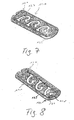
- FIGS. 7 and 8 show the holder 101 in more detail.
- FIG. 7 is a plan view of the side of the bracket 101, which faces away from the wall 104 in the installation
- FIG. 8 shows a plan view of one side of the holder 101, which faces the outer wall 104 in the installation.
- the bracket 101 has guides 127 which correspond to the guides already described above.
- an element 128 is arranged with a screw opening 130.
- the screw hole 130 acts with the eyebolt 117 for securing the second end 122 of the bracket 101 to the inner surface 103 together.
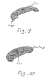
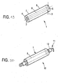
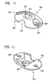
- FIGS. 9 and 10 show two views of the receptacle 118.
- FIG. 9 shows a plan view of a side of the receptacle 118, which faces away from the side wall 104 in the installation
- FIG. 10 shows a plan view of a side of the receptacle 118, which faces in the installation of the side wall 103.
- the receptacle 118 has a central screw opening 131 which cooperates with the screw 126 for attaching the receptacle 118 to the inner surface 103 of the side wall 104.
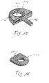
- the holder 102 is in the FIGS. 11 and 12 shown.
- FIG. 11 shows a plan view of a side of the holder 102, which faces in the installed state of the side wall 104
- FIG. 12 shows a plan view of one side of the holder 102, which faces away in the installed state of the side wall 104.
- the bracket 102 has two guides 132 connecting a start portion 133 for receiving one end of the speaker bar to an end portion 134 for locking the end of the speaker bar. Between the starting portion 133 and the end portion 134, a stopper 135 is provided to prevent unintentional detachment of the end of the box bar from the end portion 143.
- the guide 132 therefore has a substantially curved region and a subsequent linear region forming the end region.
- an element 137 is provided with a screw opening 136.
- the element 137 is arranged in a corner region of the recess 138 at the second end 123 of the holder 102.
- the screw hole 136 cooperates with the eyebolt 116 to secure the second end 123 of the bracket 102 to the inner surface 103 of the side wall 104.
- FIGS. 13 and 14 11 show views of the receptacle 119 for receiving the first end 121 of the holder 101.
- the receptacle 119 has a screw opening 139 which is adapted to cooperate with the screw element 125 for fastening the receptacle 119 to the inner surface 103 of the outer wall 104.
- the receptacle 119 on a Anbindering 124 for tethering a horse.
- FIG. 15 shows the screw 116 with a bolt 140 and a ring member 141.
- a stick or stick can be performed, especially in an emergency situation the eyebolt 116 to solve quickly.
- the further eyebolt 117 is preferably similar, in particular designed the same as in FIG. 15 shown eyebolt 116th
- brackets 101, 102 for holding a first end 112, 144 of the speaker bar 105, 106 may be considered as first brackets.
- the second ends 111, 143 of the box bar 105, 106 are held with second brackets 110, 113 on a partition wall 108.
- the divider wall is disposed between the side wall 104, which may be referred to as a first side wall, and an opposing second side wall 109 for separating two horses from each other.
- the second holders 110, 113 have ring elements 114, 115 for receiving the second end 111, 143 of the box bar 105, 106.
- the ring elements 114 of the second holder 110 extend obliquely to the horizontal and are arranged on a planar strut 145.
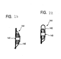
- One of these ring elements 114 is in FIG. 16 shown.
- the ring member 114 has a planar side surface 146 which is welded to the planar strut 145.
- the holder 110 has three ring elements 114, which are arranged at different heights, which correspond to the heights of the guides, in particular of the end regions of the guides, of the first holder 101.
- the ring elements 115 of the second holder 113 are arranged substantially along a vertical, wherein the heights of at least two ring elements 115 correspond to the heights of the guides, in particular of the end regions of the guides, of the holder 102.
- the arrangement of the ring elements and the guides at different heights makes it possible to keep the respective box bar at a height which corresponds to the size of each horse to be transported.
- the ring elements 115 of the second holder 113 are preferably fastened to a tubular element 147 of the partition wall 108.
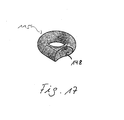
- One of these ring elements 115 is in FIG. 17 shown.
- the ring element 115 has a rounded outer surface 148, which is welded to the tubular element 147.
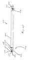
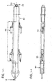
- FIG. 18 shows an example of an embodiment of the box bar 105.
- the first end 112 of the box bar 105 has a box bar end piece 153 with a slot bolt 157 on.
- the groove bolt 157 comprises a guide groove 152 between two axially spaced-apart extensions 150, 151 of the groove bolt 157.
- the extensions 150, 151 are preferably circular.
- the diameter of the groove bolt in the region of the guide groove 152 is preferably smaller than the diameter outside the guide groove 152.
- the guide groove 152 is adapted, for example, in the guides 127 of the holder 101 to be performed.
- the box pole end piece 153 also has a fastening sleeve 158, which is connected via a fastening means 154 to the speaker bar.
- the fastening means 154 is for example a fastening screw or a fastening rivet.
- the box bar 105 also has a coating tube 155, which is preferably pulled over an inner tube of the speaker bar.
- the second end 111 of the speaker bar 105 includes a hook end 156 for hooking into the ring members 114. Also, the hook end 156 is preferably connected to the speaker bar via a fastener 159 such as a mounting bolt or a mounting rivet.
- first and second brackets may for example be mounted vertically, horizontally and / or diagonally, in particular at an angle of 45 degrees to the horizontal, in the horse transporter.
- first brackets could be attached to a partition.
- the second brackets could also be attached to an outer wall.
- FIG. 19 shows a retrofittable padding 1 for padding a box pole for use in an animal transporter.
- the retrofittable padding 1 has a through hole 2 and is tubular.
- the retrofittable padding consists of a soft-elastic foam, which has a stretching property.
- a diameter 3 of the padding 1 is smaller than the diameter of a speaker bar, over which the retrofittable padding is slipped. When slipping over the padding, the hole 2 expands and thus presses against the speaker bar. The slipping over the speaker bar is done by a first opening 4 or a second opening 5 of the retrofittable padding 1.
- An inside 6 of the retrofittable padding preferably has a non-slip layer, so that slipping of the padding of the speaker bar in the longitudinal direction or in the radial direction difficult becomes.
- An outer side 7 of the padding 1 is preferably provided with a protective cover 8, which protects the padding and has a soft, hand-flattering outer side.
- the envelope 8 also acts as a kind of cover which can be replaced and
- FIG. 20 shows a box bar 11 with a retrofittable padding 1.
- the retrofittable padding 1 consists essentially of a stretchable foam part and can therefore be placed well over the box bar 11.
- the soft elastic extensible Foam is non-slip connected by these properties even with uneven outer sides 12 of the box bar 11.
- the retrofittable padding can be pulled over a box bar 11, which in turn already has a padding.
- the retrofittable padding 1 thus represents an easy way to subsequently improve the cushioning properties of an existing speaker bar.
- the box bar 11 can be hung in an animal transporter, in particular a horse transporter, for example a horse trailer, and thus delimits a box containing, for example, a horse or another animal.
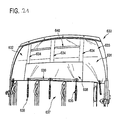
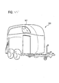
- FIG. 21 2 shows by way of example an animal transporter 630 with a tarpaulin 631 for covering a rear upper opening 632.
- the tarpaulin 631 has an air-impermeable region 633 and an air-permeable mesh area, which in FIG. 21 can not be seen and is described in more detail below.
- the tarpaulin 631 is a tarpaulin lift, that is, in this embodiment, the tarpaulin 631 is provided with leaf springs which extend in vertical pockets 634 of the tarpaulin 631.
- the leaf springs are formed so that they endeavor to unroll and thus the tarpaulin 631, so that the rear upper opening 632 is released.
- the tarpaulin further includes a tarpaulin 638 for covering the air-permeable mesh area.
- the tarpaulin 638 and the tarpaulin 631 are formed so that the tarpaulin 638 is changeable between a first state and a second state, wherein in the first state in this embodiment, the net area is completely covered and in the second state in this embodiment the net area is not is covered.
- the first state is shown.
- the tarpaulin 631 and the tarpaulin 638 have retaining means 639, 640, in particular hook-and-loop fasteners, in order to hold the tarpaulin 638 in the second state.
- the holding means 639 of the tarpaulin 638 are arranged to run along the lower outer edge of the tarpaulin 638 when the tarpaulin 638 is in the first state, that is, when the tarpaulin 638 covers the net area.
- the holding means 640 are arranged on the tarpaulin 631 such that, when the tarpaulin 638 is folded up to release the net area in the second state, they cooperate with the holding means 639 of the tarpaulin 638 to hold the tarpaulin 638 in the second state.
- This second state is exemplary in FIG. 22 shown.
- the tarpaulin 638 As shown in the in FIG. 22 As shown in the second state, the tarpaulin 638 has released the mesh area 643, this mesh area 643 is in the FIG. 22 to recognize. Furthermore, in the FIG. 22 Retaining means 641, 642, in particular Velcro, can be seen, the tarpaulin 638 in the in FIG. 21 can keep shown first state. It is also possible to fasten the tarpaulin 638 by means of the holding means 641, 642 such that the net area 643 is covered to a desired proportion, for example to 650 percent.
- the holding means 641 of the tarpaulin 631 extend vertically on the impermeable region 633 adjacent to the mesh region 643, and the holding means 642 of the tarpaulin 638 extend vertically in the first state or in the second state at the edge of the tarpaulin 638 such that in the closed first state the holding means 641 , 642 can cooperate to hold the tarpaulin 638 in this first state.
- FIG. 23 11 shows by way of example the animal transporter 630 in a state in which the tarpaulin 631 has been rolled up by means of the leaf springs, so that the rear opening 632 of the animal transporter 630 is released.
- FIG. 24 shows by way of example a further embodiment of a tarpaulin 131 with a tarpaulin 138.
- the tarpaulin 131 and the tarpaulin 138 have holding means 139, 140, in particular Velcro fasteners, which arranged in the solid state of the tarpaulin 131 and the first state of the tarpaulin 138 substantially horizontally are and can hold the tarpaulin 138 in a second state on the tarpaulin 131.
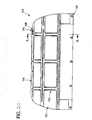
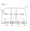
- FIG. 25 shows an example of a plan view of the after installation in the animal transporter from the inside to be seen side of the tarpaulin 131.
- the tarpaulin 131 has vertical pockets 134, in which leaf springs for automatic rolling up of the tarpaulin 131 are arranged. Furthermore, the tarpaulin 131 horizontal pockets 144, in which reinforcing struts 145 are arranged with Kochsteckkappen 146.
- the uppermost reinforcing strut 145 is preferably fastened, in particular riveted or screwed, to the upper edge of the rear upper opening of the animal transporter, that is to say in particular at the upper edge of the hood of the animal transporter.
- the tarpaulin 131 further comprises at its lower edge eyelets 147, where, for example, in FIG. 21 shown loops 35 can be attached.
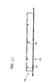
- FIG. 26 shows a sectional view taken along the line AA in FIG. 25 , In the FIG. 26 Y and Z designated areas are in the FIG. 26 and 14 shown enlarged.
- FIG. 26 It can be seen that the lower reinforcement strut 145 is disposed in the lower horizontal pocket 144 and fixed by means of a rivet 149, in particular a hollow rivet.
- FIG. 28 It can be seen that the uppermost reinforcing strut 145 is also fixed within the uppermost horizontal pocket 144 by means of a rivet 149, in particular a hollow rivet.
- the same or different reinforcing struts 145 can be arranged, which can be fixed in the same or different manner, in particular with the same or different rivets, in the respective horizontal pocket 144.
- the top and bottom reinforcing struts are preferably struts with a rectangular profile, while the intermediate reinforcing strut preferably has a round profile.
- FIG. 29 shows the side of the tarpaulin 131, which can be seen from the outside after attachment to the animal transporter.
- Holding means 139 which are attached to the tarpaulin 138
- holding means 140 which are attached to the tarpaulin 131, to recognize.
- These retaining means 139, 140 are preferably Velcro fasteners.
- Eyelets 148 can be seen, which are arranged on the lower edge of the tarpaulin 138. Through these eyelets 148, for example, in FIG. 21 shown and attachable to the eyelets 147 of the tarpaulin 131 loops 35 are passed when the tarpaulin 138 completely covers the air-impermeable network area, that is folded down, and the tarpaulin 131 is held in the fully pulled down state by means of loops 35.
- FIG. 30 shows by way of example a plan view of the tarpaulin 131, in which FIG. 24 shown state. Also the FIGS. 25 to 29 show the tarpaulin 131 in the in FIG. 24 shown state.
- top view is the slightly folded forward and upward tarpaulin 138 with the holding means 139 and the eyelets 148 can be seen.
- the impermeable portion of the tarpaulin is preferably made of PVC material, such as available from Sioen Industries. This is preferably a material which is classically used for truck tarpaulins.
- the air-permeable mesh area is preferably formed by an open-pored net, which is preferably a product of Huesker Synthetic GmbH. This material is also described in detail in the DLG Test Report 4882. Preferably, the material has at least one open porosity of about 30% or more in order to achieve sufficient aeration.
- FIG. 4 shows an animal transporter with a partition 200, wherein a rod 201 of the partition 200 is connected at an attachment point with a bottom member 202.
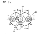
- FIG. 31 shows by way of example an enlarged view of a rod 201 of a partition, which is connected to the bottom member 202, that is a bottom plate, by means of a fastener 203.
- the fastener 203 is a member for securing a rod 201 of a partition to a floor member 202 of an animal carrier.
- the fastener 203 is in a plan view and in a view from below in the FIGS. 32 and 33 exemplified.
- the fixing member 203 has a bottom connecting portion 204 for connecting the fixing member 203 to the bottom member and a rod connecting portion 205 for connecting the fixing member 203 to the rod.
- the ground connection area 204 comprises at least two connection openings 206 for performing connection means for connecting the fastening element 203 to the floor element. These connection openings 206 serve to fasten the fastening element 203 to the floor element, in particular by means of screws or other securing means that can be carried out.
- the bar connecting portion 205 has a lock hole 207 for receiving a lock member of the bar for making a lock connection.
- the lock opening 207 has a circular area 212 and a substantially rectangular area 212 adjoining the circular area 211, a line from the center of the circular area 211 to the center of the rectangular area 212 having a non-zero angle with one of the two communication openings 206 connecting line includes.
- the circular area 211 and the rectangular area 212 are particularly explained in more detail below Figures 34 and 38 shown.
- substantially the side of the fastener 203 is shown which, when fastened to the floor element, substantially faces the pole.
- This rod side 208 is rounded.
- the fastener 203 is adapted to form a cavity with the floor member in the condition connected to the floor member into which the locking member is insertable through the latch opening 207 for securing the rod.
- the fastening element 203 has lateral cleaning openings 210, which allow a cleaning of the cavity. In addition, the cleaning openings 210 lead to material and cost savings.
- FIG. 33 is a plan view of the bottom side 209 of the fastener 203 shown, which rests in the attached state to the bottom element.
- FIG. 34 shows an example of a plan view of the rod side of the fastener 203 and the FIGS. 35 to 37 show sectional views along the in FIG. 34 shown lines CC, BB and AA.
- Figure 38 shows a plan view of the bottom side 219 of the fastener 203rd
- FIG. 39 shows by way of example a perspective view of a rod 301, in particular a partition, which is connected to a bottom element of an animal carrier by means of a fastening element is connectable.
- the rod 301 has bolts 313, four bolts 313 in this embodiment.
- the bolts for example, transverse struts of a partition wall or box bars can be connected to the bar 301.
- 314 is in FIG. 39 the side facing the bottom element in the installed state.
- FIG. 40 shows a further view of the rod 301.
- the rod 301 is a tube which has a locking element 315 with a securing pin on its in the installed state the bottom element facing side 314.
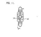
- FIG. 41 shows a view of the rod 301 along the in FIG. 40 with XX designated line.
- Figure 42 shows a plan view of the bottom member in the installed state facing side 314 of the rod 301.
- the securing pin of the locking member 315 includes with a transverse line that connects two arranged at the same height bolt, a non-zero angle. This angle is preferably 15 degrees.
- the locking element 315 with the securing pin can cooperate with the locking opening 207 of the fastening element 203 in order to easily fix the rod 301 to the floor element by means of the fastening element 203 and also to release it again easily by unlocking.
- the fastener may be used to connect partitions of different types within an animal carrier to a bottom member of the animal carrier.
- the partition wall may, for example, have a substantially U-shaped bent bar, wherein the two ends of the substantially U-shaped bent bar are connected to the bottom element.
- at least one of these ends is connected by means of the fastening element with the bottom element.
- One of these ends therefore preferably comprises a locking element which cooperates with a locking opening of the fastening element which is fastened to the floor element in order to lock the rod of the separating wall and thus the separating wall to the fastening element, so that the separating wall is fastened to the floor element ,
- FIG. 43 One type of partition, which according to the invention can be connected by means of a fastening element to a bottom element of an animal carrier, is shown by way of example in FIG FIG. 43 shown.
- FIG. 43 shows the interior of an animal transporter, in particular a horse trailer, with a partition wall 300.
- the partition wall 300 has a central rod 301 which is fastened by means of the fastening element 203 to the bottom element 302.
- Partition elements 317 are attached to the rod 301 by means of the bolts 313.
- the partition wall elements 317 furthermore have ring elements 318 with which the partition wall elements 317 can be connected, for example by means of box poles 316, to side walls of the animal transporter.
- two partition wall elements 317 are connected by means of bolts 313 on the middle bar 301 and also by means of two box bars 316 to the side walls of the animal transporter.
- the center bar 301 extends from the floor member 302 to the corner of the animal carrier to which the bar 301 is also fixed, preferably screwed.
- FIG. 44 Another partition, which according to the invention can be fastened to a base element by means of a fastening means, is exemplary in FIG FIG. 44 shown.
- the partition wall 400 has a frame formed by rods 419, which encloses a partition plate 420 made of plastic or wood, for example.
- the dividing wall 400 is connected to the bottom element 402 of the animal transporter by means of a rod 401 and a fastening element according to the invention.
- the partition wall 400 further includes ring members 421 which are particularly secured to the frame 419 of the divider 400 and which are engageable with corresponding protrusions of box poles 416 to connect the divider wall 400 to the side panels 422 of the animal carrier via the box poles 416.
- the ring members 421 and the box bars 416 are arranged so that both a front end of the partition wall 400 and a rear end of the partition wall 400 are connected to both side walls 422, respectively.
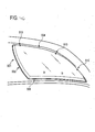
- FIG. 45 shows by way of example an animal transporter 500 with a Ausstellpper 501.
- An enlarged external view of the Ausstellromes 501 is exemplary in FIG. 46 shown.
- an interior view of the Ausstellppers 501 is exemplary in FIG. 47 shown.
- the pop-up window 501 covers a front side opening 502 of the animal carrier 500.
- the opening 502 has a curved front first side 504 that faces the direction of travel, a second side 505 that faces away from the direction of travel, and a lower third side 506 that defines the opening 502 downward.
- the pop-up window 501 has corresponding sides facing the respective sides of the opening 502 in the closed state.
- the first page 504 extends from one front corner of the opening 502 upwardly and rearwardly to a rear upper corner of the opening 502. This entire side 504 is considered as the direction of travel facing side.
- the second side 505 extends with a slight outer arc from the rear upper corner to a rear lower corner, and the side 506 extends substantially horizontally from the rear lower corner to the front lower corner.
- the opening 502 and thus the corresponding Ausstellari 501 thus have the shape of a distorted triangle.
- the opening window and the corresponding opening may also have at least one further side and, for example, the shape of a quadrilateral.
- the opening 502 is penetrated by horizontal struts 503 in order to stabilize the animal transporter in this area.
- FIG. 49 shows by way of example the opening 502 with the Ausstellpper 501 in an open state in an outside view and FIG. 50 shows an example of the opening 502 with the Ausstellpper 501 in an interior view.
- FIG. 49 It can be seen that the edge of the opening 502 is provided with a window frame 511.
- the window frame 511 can be riveted, screwed or glued to the edge of the opening 502, for example. Furthermore, in FIG. 49 it can be seen that the window frame 511 has an insulating rubber 512 running along the window frame.
- the first side 504 of the opening 502 facing side of the Ausstellromes 501 is connected to the corresponding side of the window frame 511 by means of cylindrical rubber elements.
- One of these rubber elements 507 is exemplified in FIG. 48 shown.
- the rubber element is cylindrical, wherein at opposite ends of the rubber element 507 screw 508 for screwing the rubber element with the window frame 511 and the Ausstellari 501 are present. That is, for connecting the side of the window frame 511 facing the first side of the opening 502, a plurality of rubber members 507 are screwed along this side of the window frame 511.
- the respective opposite end of the rubber element 507 is screwed to the corresponding side of the Ausstellwitppers 501.
- this screw connection takes place at least at the three connection points 513, which in FIG. 46 are shown.
- a handle 509 is mounted substantially centrally on the lower side of the opening window 501.
- the handle 509 may be bolted or glued to the hinged window 501, for example.
- the handle 509 is connected by means of a leaf spring 510 to the opening 502, in particular to the third side 506 of the opening 502.
- the leaf spring 510 is pivotally connected to the opening 502.
- the leaf spring 501 may be a continuous leaf spring guided by the handle, or two-leaf springs 510 may be provided, each connecting one end of the handle 509 to the opening 502.
- the leaf spring 510 is formed to be in the in the Figures 46 and 47 shown closed state holds the Ausstellaris 501 in the closed state, wherein the opening of the Ausstellromes 501 is pressed against a spring resistance by means of the handle 509 from the inside against the Ausstellrous 501 until a dead center of the leaf spring 510 is exceeded and the spring force of the leaf spring 510 the Ausstellrous 501 opens and in particular in the Figures 49 and 50 shown opened state.
- animal transporters have certain features, these animal transporters may also have more or less inventive features.
- an animal transporter may have all the features disclosed, in particular in the claims.
- Features described in the above-mentioned embodiments as belonging to different animal transporters may also be realized in a single animal transporter.
- the invention relates to a holder of an attached at one end of the box bar for an animal transporter, in particular a horse transporter, with a guide for another end of the speaker bar, wherein the guide is formed so that the other end can engage in the guide, wherein the Guide connecting a starting portion for receiving the other end with an end portion for locking the other end, wherein between the input portion and the end portion, a stop for preventing accidental detachment of the other end is formed from the end portion.
Landscapes
- Engineering & Computer Science (AREA)
- Life Sciences & Earth Sciences (AREA)
- Transportation (AREA)
- Mechanical Engineering (AREA)
- Environmental Sciences (AREA)
- Zoology (AREA)
- Animal Husbandry (AREA)
- Biodiversity & Conservation Biology (AREA)
- Health & Medical Sciences (AREA)
- Public Health (AREA)
- Housing For Livestock And Birds (AREA)
Priority Applications (1)
| Application Number | Priority Date | Filing Date | Title |
|---|---|---|---|
| PL10156386T PL2228256T3 (pl) | 2009-03-13 | 2010-03-12 | Transporter dla zwierząt |
Applications Claiming Priority (1)
| Application Number | Priority Date | Filing Date | Title |
|---|---|---|---|
| DE202009004015U DE202009004015U1 (de) | 2009-03-13 | 2009-03-13 | Tiertransporter |
Publications (2)
| Publication Number | Publication Date |
|---|---|
| EP2228256A1 EP2228256A1 (de) | 2010-09-15 |
| EP2228256B1 true EP2228256B1 (de) | 2015-11-11 |
Family
ID=40847672
Family Applications (1)
| Application Number | Title | Priority Date | Filing Date |
|---|---|---|---|
| EP10156386.4A Active EP2228256B1 (de) | 2009-03-13 | 2010-03-12 | Tiertransporter |
Country Status (4)
| Country | Link |
|---|---|
| EP (1) | EP2228256B1 (pl) |
| DE (1) | DE202009004015U1 (pl) |
| DK (1) | DK2228256T3 (pl) |
| PL (1) | PL2228256T3 (pl) |
Cited By (1)
| Publication number | Priority date | Publication date | Assignee | Title |
|---|---|---|---|---|
| DE202021104489U1 (de) | 2021-08-20 | 2021-09-02 | Böckmann Fahrzeugwerke GmbH | Pferdeanhänger zum Transportieren von mindestens zwei Pferden |
Families Citing this family (3)
| Publication number | Priority date | Publication date | Assignee | Title |
|---|---|---|---|---|
| DE202012103810U1 (de) | 2012-10-04 | 2014-01-16 | Ulrich Humbaur | Fahrzeuganhänger |
| DE202012103811U1 (de) | 2012-10-04 | 2014-01-15 | Ulrich Humbaur | Sicherungseinrichtung |
| DE202015101065U1 (de) | 2015-03-05 | 2016-06-09 | Ulrich Humbaur | Fahrzeug, insbesondere Tiertransporter |
Family Cites Families (8)
| Publication number | Priority date | Publication date | Assignee | Title |
|---|---|---|---|---|
| US866811A (en) * | 1907-01-25 | 1907-09-24 | Johann Riedemann | Device for the barriers of horse-stables. |
| DE3104374C2 (de) | 1981-02-07 | 1985-01-31 | Adorno + Leisentritt Fahrzeugbau Gmbh, 4712 Werne | Abdeckplane für den Laderaum eines Nutzfahrzeuges |
| EP0619786B1 (en) * | 1992-01-07 | 1996-10-09 | Dualmist Pty Ltd | Transportable animal enclosures |
| SE9400146L (sv) * | 1994-01-20 | 1995-07-21 | Bengt Knaust | Anordning vid djurbox, som framför djuret avgränsas av en bom samt en bom för avgränsning av djurbox |
| US6895897B1 (en) * | 2000-08-17 | 2005-05-24 | Exiss Aluminum Trailers, Inc. | Flush interlocking sidewall mounted slam latch |
| DE20309373U1 (de) * | 2003-06-16 | 2003-08-28 | Kielinger, Susanne, 72270 Baiersbronn | Verbindungssystem zur lösbaren Befestigung von Gegenständen an einer Montagefläche |
| DE20313374U1 (de) * | 2003-08-28 | 2003-11-13 | Mitzel, Siegfried, 86655 Harburg | Sperrstangenverriegelung |
| DE202006010385U1 (de) | 2006-07-05 | 2006-09-14 | Böckmann Fahrzeugwerke GmbH | Boxenstange |
-
2009
- 2009-03-13 DE DE202009004015U patent/DE202009004015U1/de not_active Expired - Lifetime
-
2010
- 2010-03-12 EP EP10156386.4A patent/EP2228256B1/de active Active
- 2010-03-12 PL PL10156386T patent/PL2228256T3/pl unknown
- 2010-03-12 DK DK10156386.4T patent/DK2228256T3/en active
Cited By (1)
| Publication number | Priority date | Publication date | Assignee | Title |
|---|---|---|---|---|
| DE202021104489U1 (de) | 2021-08-20 | 2021-09-02 | Böckmann Fahrzeugwerke GmbH | Pferdeanhänger zum Transportieren von mindestens zwei Pferden |
Also Published As
| Publication number | Publication date |
|---|---|
| PL2228256T3 (pl) | 2016-05-31 |
| EP2228256A1 (de) | 2010-09-15 |
| DE202009004015U1 (de) | 2009-07-09 |
| DK2228256T3 (en) | 2016-02-15 |
Similar Documents
| Publication | Publication Date | Title |
|---|---|---|
| DE102005037385B4 (de) | Sitz einer hinteren Sitzreihe eines Kraftfahrzeuges | |
| DE20013207U1 (de) | Laufgitter für Kleinkinder mit kombinierter Trage | |
| DE2102882A1 (de) | Auseinandernehmbarer Transportbe halter | |
| EP2558168B1 (de) | Parkouraufbau | |
| EP2228256B1 (de) | Tiertransporter | |
| DE102017101513A1 (de) | Runge für einen Nutzfahrzeug- oder Anhängeraufbau | |
| DE102020207386A1 (de) | Rampenvorrichtung einer tür für ein fahrzeug | |
| EP2330020B1 (de) | Seitenabdeckung eines Nutzfahrzeugaufbaus | |
| DE102015107825A1 (de) | Liegefläche für Aufstelldach | |
| DE69924444T3 (de) | Schutzvorrichtung insbesondere Sicherheitsnetz für Kraftfahrzeuge | |
| DE202009011405U1 (de) | Kinderbett | |
| DE102022115254A1 (de) | Zurreinrichtung zur Teilladungssicherung in Fahrtrichtung eines Nutzfahrzeugaufbaus, Ladungssicherungssystem und Nutzfahrzeugaufbau mit einer solchen Zurreinrichtung | |
| EP3753787A1 (de) | Kraftfahrzeug mit einer laderaumabdeckung | |
| EP2842841A2 (de) | Seitenabdeckung eines Nutzfahrzeugaufbaus | |
| DE19622137A1 (de) | Gestell, insb. für die Verkleidung von fahrbaren, konischen Mülltonnen | |
| DE202022102312U1 (de) | Öffenbares Seitenplanenwandsystem | |
| DE102007060726B3 (de) | Seitenteil für ein Bett sowie Bettgestell mit einem derartigen Seitenteil | |
| EP3243678A1 (de) | Nutzfahrzeugaufbau | |
| DE202020101194U1 (de) | Bergungsvorrichtung | |
| DE19729427C2 (de) | Haltevorrichtung zum Lagern eines Hardtops | |
| EP3002143B1 (de) | Seitenabdeckung eines nutzfahrzeugaufbaus | |
| DE102011117441A1 (de) | Vorrichtung zur Halterung von wenigstens einem Transportsicherungsnetz, in einem Fahrzeug | |
| DE3425016A1 (de) | Schiebeverdeck-planengestell | |
| DE19630765A1 (de) | Campingbus | |
| DE2731948C2 (pl) |
Legal Events
| Date | Code | Title | Description |
|---|---|---|---|
| PUAI | Public reference made under article 153(3) epc to a published international application that has entered the european phase |
Free format text: ORIGINAL CODE: 0009012 |
|
| AK | Designated contracting states |
Kind code of ref document: A1 Designated state(s): AT BE BG CH CY CZ DE DK EE ES FI FR GB GR HR HU IE IS IT LI LT LU LV MC MK MT NL NO PL PT RO SE SI SK SM TR |
|
| AX | Request for extension of the european patent |
Extension state: AL BA ME RS |
|
| 17P | Request for examination filed |
Effective date: 20110315 |
|
| 17Q | First examination report despatched |
Effective date: 20111111 |
|
| GRAP | Despatch of communication of intention to grant a patent |
Free format text: ORIGINAL CODE: EPIDOSNIGR1 |
|
| INTG | Intention to grant announced |
Effective date: 20150609 |
|
| GRAS | Grant fee paid |
Free format text: ORIGINAL CODE: EPIDOSNIGR3 |
|
| GRAA | (expected) grant |
Free format text: ORIGINAL CODE: 0009210 |
|
| AK | Designated contracting states |
Kind code of ref document: B1 Designated state(s): AT BE BG CH CY CZ DE DK EE ES FI FR GB GR HR HU IE IS IT LI LT LU LV MC MK MT NL NO PL PT RO SE SI SK SM TR |
|
| REG | Reference to a national code |
Ref country code: GB Ref legal event code: FG4D Free format text: NOT ENGLISH |
|
| REG | Reference to a national code |
Ref country code: CH Ref legal event code: EP Ref country code: CH Ref legal event code: NV Representative=s name: WEINMANN ZIMMERLI, CH |
|
| REG | Reference to a national code |
Ref country code: IE Ref legal event code: FG4D Free format text: LANGUAGE OF EP DOCUMENT: GERMAN |
|
| REG | Reference to a national code |
Ref country code: AT Ref legal event code: REF Ref document number: 760268 Country of ref document: AT Kind code of ref document: T Effective date: 20151215 |
|
| REG | Reference to a national code |
Ref country code: DE Ref legal event code: R096 Ref document number: 502010010620 Country of ref document: DE |
|
| REG | Reference to a national code |
Ref country code: DK Ref legal event code: T3 Effective date: 20160211 |
|
| REG | Reference to a national code |
Ref country code: SE Ref legal event code: TRGR |
|
| REG | Reference to a national code |
Ref country code: LT Ref legal event code: MG4D |
|
| REG | Reference to a national code |
Ref country code: FR Ref legal event code: PLFP Year of fee payment: 7 |
|
| REG | Reference to a national code |
Ref country code: NL Ref legal event code: FP |
|
| PG25 | Lapsed in a contracting state [announced via postgrant information from national office to epo] |
Ref country code: LT Free format text: LAPSE BECAUSE OF FAILURE TO SUBMIT A TRANSLATION OF THE DESCRIPTION OR TO PAY THE FEE WITHIN THE PRESCRIBED TIME-LIMIT Effective date: 20151111 Ref country code: HR Free format text: LAPSE BECAUSE OF FAILURE TO SUBMIT A TRANSLATION OF THE DESCRIPTION OR TO PAY THE FEE WITHIN THE PRESCRIBED TIME-LIMIT Effective date: 20151111 Ref country code: IS Free format text: LAPSE BECAUSE OF FAILURE TO SUBMIT A TRANSLATION OF THE DESCRIPTION OR TO PAY THE FEE WITHIN THE PRESCRIBED TIME-LIMIT Effective date: 20160311 Ref country code: IT Free format text: LAPSE BECAUSE OF FAILURE TO SUBMIT A TRANSLATION OF THE DESCRIPTION OR TO PAY THE FEE WITHIN THE PRESCRIBED TIME-LIMIT Effective date: 20151111 Ref country code: ES Free format text: LAPSE BECAUSE OF FAILURE TO SUBMIT A TRANSLATION OF THE DESCRIPTION OR TO PAY THE FEE WITHIN THE PRESCRIBED TIME-LIMIT Effective date: 20151111 Ref country code: NO Free format text: LAPSE BECAUSE OF FAILURE TO SUBMIT A TRANSLATION OF THE DESCRIPTION OR TO PAY THE FEE WITHIN THE PRESCRIBED TIME-LIMIT Effective date: 20160211 |
|
| PG25 | Lapsed in a contracting state [announced via postgrant information from national office to epo] |
Ref country code: GR Free format text: LAPSE BECAUSE OF FAILURE TO SUBMIT A TRANSLATION OF THE DESCRIPTION OR TO PAY THE FEE WITHIN THE PRESCRIBED TIME-LIMIT Effective date: 20160212 Ref country code: PT Free format text: LAPSE BECAUSE OF FAILURE TO SUBMIT A TRANSLATION OF THE DESCRIPTION OR TO PAY THE FEE WITHIN THE PRESCRIBED TIME-LIMIT Effective date: 20160311 Ref country code: LV Free format text: LAPSE BECAUSE OF FAILURE TO SUBMIT A TRANSLATION OF THE DESCRIPTION OR TO PAY THE FEE WITHIN THE PRESCRIBED TIME-LIMIT Effective date: 20151111 Ref country code: FI Free format text: LAPSE BECAUSE OF FAILURE TO SUBMIT A TRANSLATION OF THE DESCRIPTION OR TO PAY THE FEE WITHIN THE PRESCRIBED TIME-LIMIT Effective date: 20151111 |
|
| PG25 | Lapsed in a contracting state [announced via postgrant information from national office to epo] |
Ref country code: CZ Free format text: LAPSE BECAUSE OF FAILURE TO SUBMIT A TRANSLATION OF THE DESCRIPTION OR TO PAY THE FEE WITHIN THE PRESCRIBED TIME-LIMIT Effective date: 20151111 |
|
| REG | Reference to a national code |
Ref country code: DE Ref legal event code: R097 Ref document number: 502010010620 Country of ref document: DE |
|
| PG25 | Lapsed in a contracting state [announced via postgrant information from national office to epo] |
Ref country code: RO Free format text: LAPSE BECAUSE OF FAILURE TO SUBMIT A TRANSLATION OF THE DESCRIPTION OR TO PAY THE FEE WITHIN THE PRESCRIBED TIME-LIMIT Effective date: 20151111 Ref country code: EE Free format text: LAPSE BECAUSE OF FAILURE TO SUBMIT A TRANSLATION OF THE DESCRIPTION OR TO PAY THE FEE WITHIN THE PRESCRIBED TIME-LIMIT Effective date: 20151111 Ref country code: SM Free format text: LAPSE BECAUSE OF FAILURE TO SUBMIT A TRANSLATION OF THE DESCRIPTION OR TO PAY THE FEE WITHIN THE PRESCRIBED TIME-LIMIT Effective date: 20151111 Ref country code: SK Free format text: LAPSE BECAUSE OF FAILURE TO SUBMIT A TRANSLATION OF THE DESCRIPTION OR TO PAY THE FEE WITHIN THE PRESCRIBED TIME-LIMIT Effective date: 20151111 |
|
| PLBE | No opposition filed within time limit |
Free format text: ORIGINAL CODE: 0009261 |
|
| STAA | Information on the status of an ep patent application or granted ep patent |
Free format text: STATUS: NO OPPOSITION FILED WITHIN TIME LIMIT |
|
| 26N | No opposition filed |
Effective date: 20160812 |
|
| PG25 | Lapsed in a contracting state [announced via postgrant information from national office to epo] |
Ref country code: LU Free format text: LAPSE BECAUSE OF FAILURE TO SUBMIT A TRANSLATION OF THE DESCRIPTION OR TO PAY THE FEE WITHIN THE PRESCRIBED TIME-LIMIT Effective date: 20160312 Ref country code: MC Free format text: LAPSE BECAUSE OF FAILURE TO SUBMIT A TRANSLATION OF THE DESCRIPTION OR TO PAY THE FEE WITHIN THE PRESCRIBED TIME-LIMIT Effective date: 20151111 |
|
| PG25 | Lapsed in a contracting state [announced via postgrant information from national office to epo] |
Ref country code: SI Free format text: LAPSE BECAUSE OF FAILURE TO SUBMIT A TRANSLATION OF THE DESCRIPTION OR TO PAY THE FEE WITHIN THE PRESCRIBED TIME-LIMIT Effective date: 20151111 |
|
| REG | Reference to a national code |
Ref country code: IE Ref legal event code: MM4A |
|
| PG25 | Lapsed in a contracting state [announced via postgrant information from national office to epo] |
Ref country code: IE Free format text: LAPSE BECAUSE OF NON-PAYMENT OF DUE FEES Effective date: 20160312 |
|
| REG | Reference to a national code |
Ref country code: FR Ref legal event code: PLFP Year of fee payment: 8 |
|
| PG25 | Lapsed in a contracting state [announced via postgrant information from national office to epo] |
Ref country code: MT Free format text: LAPSE BECAUSE OF FAILURE TO SUBMIT A TRANSLATION OF THE DESCRIPTION OR TO PAY THE FEE WITHIN THE PRESCRIBED TIME-LIMIT Effective date: 20151111 |
|
| REG | Reference to a national code |
Ref country code: FR Ref legal event code: PLFP Year of fee payment: 9 |
|
| PG25 | Lapsed in a contracting state [announced via postgrant information from national office to epo] |
Ref country code: CY Free format text: LAPSE BECAUSE OF FAILURE TO SUBMIT A TRANSLATION OF THE DESCRIPTION OR TO PAY THE FEE WITHIN THE PRESCRIBED TIME-LIMIT Effective date: 20151111 Ref country code: HU Free format text: LAPSE BECAUSE OF FAILURE TO SUBMIT A TRANSLATION OF THE DESCRIPTION OR TO PAY THE FEE WITHIN THE PRESCRIBED TIME-LIMIT; INVALID AB INITIO Effective date: 20100312 |
|
| PG25 | Lapsed in a contracting state [announced via postgrant information from national office to epo] |
Ref country code: TR Free format text: LAPSE BECAUSE OF FAILURE TO SUBMIT A TRANSLATION OF THE DESCRIPTION OR TO PAY THE FEE WITHIN THE PRESCRIBED TIME-LIMIT Effective date: 20151111 Ref country code: MK Free format text: LAPSE BECAUSE OF FAILURE TO SUBMIT A TRANSLATION OF THE DESCRIPTION OR TO PAY THE FEE WITHIN THE PRESCRIBED TIME-LIMIT Effective date: 20151111 |
|
| PG25 | Lapsed in a contracting state [announced via postgrant information from national office to epo] |
Ref country code: BG Free format text: LAPSE BECAUSE OF FAILURE TO SUBMIT A TRANSLATION OF THE DESCRIPTION OR TO PAY THE FEE WITHIN THE PRESCRIBED TIME-LIMIT Effective date: 20151111 |
|
| P01 | Opt-out of the competence of the unified patent court (upc) registered |
Effective date: 20230420 |
|
| PGFP | Annual fee paid to national office [announced via postgrant information from national office to epo] |
Ref country code: SE Payment date: 20250311 Year of fee payment: 16 |
|
| PGFP | Annual fee paid to national office [announced via postgrant information from national office to epo] |
Ref country code: NL Payment date: 20250324 Year of fee payment: 16 Ref country code: DK Payment date: 20250321 Year of fee payment: 16 |
|
| PGFP | Annual fee paid to national office [announced via postgrant information from national office to epo] |
Ref country code: AT Payment date: 20250319 Year of fee payment: 16 Ref country code: BE Payment date: 20250320 Year of fee payment: 16 |
|
| PGFP | Annual fee paid to national office [announced via postgrant information from national office to epo] |
Ref country code: PL Payment date: 20250225 Year of fee payment: 16 Ref country code: FR Payment date: 20250324 Year of fee payment: 16 |
|
| PGFP | Annual fee paid to national office [announced via postgrant information from national office to epo] |
Ref country code: GB Payment date: 20250324 Year of fee payment: 16 |
|
| PGFP | Annual fee paid to national office [announced via postgrant information from national office to epo] |
Ref country code: DE Payment date: 20250409 Year of fee payment: 16 |
|
| PGFP | Annual fee paid to national office [announced via postgrant information from national office to epo] |
Ref country code: CH Payment date: 20250401 Year of fee payment: 16 |