EP2228256B1 - Animal transporter - Google Patents
Animal transporter Download PDFInfo
- Publication number
- EP2228256B1 EP2228256B1 EP10156386.4A EP10156386A EP2228256B1 EP 2228256 B1 EP2228256 B1 EP 2228256B1 EP 10156386 A EP10156386 A EP 10156386A EP 2228256 B1 EP2228256 B1 EP 2228256B1
- Authority
- EP
- European Patent Office
- Prior art keywords
- mounting
- transporter
- animal
- guide
- tarpaulin
- Prior art date
- Legal status (The legal status is an assumption and is not a legal conclusion. Google has not performed a legal analysis and makes no representation as to the accuracy of the status listed.)
- Active
Links
- 241001465754 Metazoa Species 0.000 title claims description 135
- 238000003780 insertion Methods 0.000 claims description 4
- 230000037431 insertion Effects 0.000 claims description 4
- 238000005192 partition Methods 0.000 description 47
- 239000000463 material Substances 0.000 description 22
- 239000006260 foam Substances 0.000 description 13
- 238000012360 testing method Methods 0.000 description 7
- 230000003014 reinforcing effect Effects 0.000 description 6
- 238000004140 cleaning Methods 0.000 description 5
- 238000009434 installation Methods 0.000 description 5
- 230000006378 damage Effects 0.000 description 4
- 230000001681 protective effect Effects 0.000 description 4
- 241000283086 Equidae Species 0.000 description 3
- 208000027418 Wounds and injury Diseases 0.000 description 3
- 238000011161 development Methods 0.000 description 3
- 208000014674 injury Diseases 0.000 description 3
- 229920005862 polyol Polymers 0.000 description 3
- 150000003077 polyols Chemical class 0.000 description 3
- UPMLOUAZCHDJJD-UHFFFAOYSA-N 4,4'-Diphenylmethane Diisocyanate Chemical compound C1=CC(N=C=O)=CC=C1CC1=CC=C(N=C=O)C=C1 UPMLOUAZCHDJJD-UHFFFAOYSA-N 0.000 description 2
- 239000012948 isocyanate Substances 0.000 description 2
- 150000002513 isocyanates Chemical class 0.000 description 2
- 239000002184 metal Substances 0.000 description 2
- 238000003825 pressing Methods 0.000 description 2
- 238000012545 processing Methods 0.000 description 2
- 239000007787 solid Substances 0.000 description 2
- 238000009423 ventilation Methods 0.000 description 2
- 244000007853 Sarothamnus scoparius Species 0.000 description 1
- 239000012190 activator Substances 0.000 description 1
- 239000000853 adhesive Substances 0.000 description 1
- 238000005273 aeration Methods 0.000 description 1
- 230000015572 biosynthetic process Effects 0.000 description 1
- 230000009194 climbing Effects 0.000 description 1
- 239000011248 coating agent Substances 0.000 description 1
- 238000000576 coating method Methods 0.000 description 1
- 238000004891 communication Methods 0.000 description 1
- 150000001875 compounds Chemical class 0.000 description 1
- 238000013461 design Methods 0.000 description 1
- 201000010099 disease Diseases 0.000 description 1
- 208000037265 diseases, disorders, signs and symptoms Diseases 0.000 description 1
- 239000000975 dye Substances 0.000 description 1
- 230000000694 effects Effects 0.000 description 1
- 239000000203 mixture Substances 0.000 description 1
- 238000000465 moulding Methods 0.000 description 1
- 239000004033 plastic Substances 0.000 description 1
- 238000002360 preparation method Methods 0.000 description 1
- 230000002787 reinforcement Effects 0.000 description 1
- 238000009420 retrofitting Methods 0.000 description 1
- 238000005096 rolling process Methods 0.000 description 1
- 239000003381 stabilizer Substances 0.000 description 1
- 239000002023 wood Substances 0.000 description 1
Images


Classifications
-
- B—PERFORMING OPERATIONS; TRANSPORTING
- B60—VEHICLES IN GENERAL
- B60P—VEHICLES ADAPTED FOR LOAD TRANSPORTATION OR TO TRANSPORT, TO CARRY, OR TO COMPRISE SPECIAL LOADS OR OBJECTS
- B60P3/00—Vehicles adapted to transport, to carry or to comprise special loads or objects
- B60P3/04—Vehicles adapted to transport, to carry or to comprise special loads or objects for transporting animals
-
- A—HUMAN NECESSITIES
- A01—AGRICULTURE; FORESTRY; ANIMAL HUSBANDRY; HUNTING; TRAPPING; FISHING
- A01K—ANIMAL HUSBANDRY; CARE OF BIRDS, FISHES, INSECTS; FISHING; REARING OR BREEDING ANIMALS, NOT OTHERWISE PROVIDED FOR; NEW BREEDS OF ANIMALS
- A01K1/00—Housing animals; Equipment therefor
- A01K1/04—Tethering-poles or the like
-
- B—PERFORMING OPERATIONS; TRANSPORTING
- B60—VEHICLES IN GENERAL
- B60P—VEHICLES ADAPTED FOR LOAD TRANSPORTATION OR TO TRANSPORT, TO CARRY, OR TO COMPRISE SPECIAL LOADS OR OBJECTS
- B60P7/00—Securing or covering of load on vehicles
- B60P7/06—Securing of load
- B60P7/135—Securing or supporting by load bracing means
- B60P7/15—Securing or supporting by load bracing means the load bracing means comprising a movable bar
Definitions
- the invention relates to a holder of a speaker bar for an animal transporter, in particular in a horse transporter. Furthermore, the invention relates to a speaker bar, a support system for a speaker bar and an animal transporter, in particular a horse transporter.
- Box poles for animal transporters are for example from the DE 20 2006 010 385 U1 known. Such box poles are generally mounted transversely to the direction of travel of the animal carrier, in particular the horse transporter, for example, to limit a horse box or to prevent an animal located on the animal transporter from climbing down the animal transporter. The pit poles serve to keep the animal on the animal transporter.
- box bars may be made of a hard material such as a metal. It is desirable to protect the animal, in particular horse, to be transported in an animal transport vehicle from pressure loads and from risk of injury. Pressure loads arise, for example, in the chest area of the horse, when this bumps against a speaker bar.
- Such box poles are usually releasably attached to a holder for the speaker bar.
- a speaker bar For example, one end of a speaker bar is fixed in a first holder and the other end of a speaker bar is mounted in a second holder in accordance with a holding mechanism of the speaker bar.
- the two brackets are often located inside an animal transporter, particularly a horse transporter, and the box bar is attached to these brackets to confine a box, such as a horse box.
- Another or alternative object is to increase the flexibility of an animal carrier, in particular a horse transporter.
- a holder of an attached at one end of the box bar for an animal transporter, in particular a horse transporter provided.
- the holder has a guide of the other end of the speaker bar, the other end engages the guide.
- the guide connects a start portion for receiving the other end to an end portion for locking the other end. Between the starting portion and the end portion, the guide forms a stop for preventing accidental detachment of the other end from the end portion.
- the holder may for example be attached to an animal transporter, in particular to a horse transporter.
- rivets are suitable for fastening the holder.
- the other end of the speaker bar is bolt-shaped educated.
- the guide can be, for example, a recess in a plate, preferably a metal plate, which preferably has a narrow, oblong shape and describes a path around a tongue.
- the tongue then forms the stop.
- the starting area or entrance area of the guide serves to receive the other end, for example the bolt-shaped end of a box bar and to guide it to an end area.
- the end portion of the guide then defines the end seat or end position of the other end of the speaker bar.
- the other end of the speaker bar may be formed, for example, as a pin or a bolt.
- the formation of the stop between the starting region and the end region of the guide can mean, for example, that the stop is formed on or on the path which the guide describes.
- the stop can be used as a stop, a portion of a wall that defines the guide at least partially defined.
- the holder has a plurality of the guides, preferably three guides, which are arranged side by side in a first plane.
- the holder has a plurality of the guides, preferably three guides, which are arranged one above the other.
- Placing the plurality of guides side by side also means that the end portions of the guides are juxtaposed, resulting in different end positions of the other end of a speaker bar when inserted into another adjacent guide.
- the size of a limited with such a speaker bar box can thus be changed.
- three different box sizes are well suited for horse transporters.
- a desired dimensional variability of the box can be determined. For example, the box can only be adjusted in height if the end regions of the guides are arranged vertically one above the other on an animal transporter. For example, the box can only be adjusted in length if the end regions of the guides are arranged horizontally next to one another on an animal transporter.
- the holder is arranged with a plurality of guides on an animal transporter such that boxes of different height and length can be formed.
- the end portions of the guides of the holder on an inner side wall of the animal transporter different heights from the ground and arranged side by side in a horizontal direction.
- the guide is at least partially arcuate.
- An arcuate design of the guide results in a simple sliding of the other end of a speaker bar through the guide. Unintentional hooking of the other end in the guide is thus avoided or at least reduced.
- the holder has a first plane, in which the at least one guide is arranged, and a second plane, in which fastening means for fastening the holder, for example on an animal transporter, in particular on a horse transporter, are arranged, wherein the first Level and the second level are parallel and spaced from each other.
- the second level for example, has holes with which the holder can be attached, for example, to the inside of an animal carrier.
- the second level with the at least one guide is offset from this mounting plane so that a cavity can form between the wall of an animal carrier and the first level.
- a part of the other end of a box bar or a part of a bolt can be received by this cavity or in the space between the first level and the second level.
- the object is also achieved with a box bar for use in an animal transporter, in particular horse transporter.
- the box bar has an end for hanging on an animal carrier and the other end for insertion into a guide of a holder according to the invention.
- Hooking also provides releasable attachment.
- the one end of the box bar preferably has a U-shaped configuration with the U having unequal length legs. This U-shaped end can be plugged, for example, for attachment through a ring to an animal transporter.
- the other end is designed to allow movements of the other end along the guide and movements of the other End to prevent in the longitudinal direction of the speaker bar.
- the position of the speaker bar is better defined and accidental slippage is prevented. This is achieved, for example, in that at the other end of the box bar a section has a smaller cross-section than the adjacent sections, or in that the other end has a taper.
- the object is also achieved with a holder system for a box bar for use in an animal transporter, in particular in a horse transporter.
- the mounting system includes a bracket according to the invention and a second bracket for receiving one end of the speaker bar, the bracket system being adapted to permit release of the other end of the speaker bar from the second bracket only when the other end is disengaged.
- the second bracket is generally opposite the first bracket. If the first holder has a plurality of guides, then the second holder also has a plurality of holder devices, for example rings or eyelets, which respectively lie opposite the end position of the corresponding guide.
- the wall of the animal transporter is preferably a lateral outer wall of the animal transporter and / or an inner wall of the animal transporter, in particular an inner partition of the animal transporter, which separates two areas of the interior of the animal carrier, for example, to transport two horses separately in the animal transporter.
- the wall of the animal carrier is an outer wall
- the first surface of the outer wall is preferably the inner surface of the outer wall
- the second surface of the outer wall is preferably the outer surface of the outer wall.
- the holder for the speaker bar can be detached from the inner wall such that the holder falls within the animal carrier on the ground by the fastening means outside the animal carrier on the outer surface of the outer wall of the animal carrier is released.
- the at least one fastening means preferably has a screw, in particular an eyebolt.
- An eyebolt can be easily turned by, for example, a handle, such as a broom handle, passed through the eyebolt and then the eyebolt is rotated by means of the stem. This allows a quick release of the fastener, even if the bracket is firmly screwed.
- the support system has a receptacle attachable to the first surface of the wall for receiving a first end of the support as a first attachment means and a second attachment means for securing a second end of the support, wherein when the support is attached to the first surface of the wall is fixed, the second attachment means on the second surface is detachable, so that the holder can be removed from the receptacle to release the holder from the first surface of the wall.
- the second fastening means is preferably a screw, in particular an eyebolt. By loosening the second fastener, the bracket can be quickly and easily removed from the wall. It is therefore only necessary to release the second fastening means, in particular the screw, in order to remove the holder from the wall.
- the first surface is an inner surface of an outer wall of an animal carrier
- the second surface is the outer surface of this side wall.
- the receptacle preferably has a Anbindering. This makes it possible to attach animals, especially horses, to the recording.
- the recording thus fulfills at least two functions, on the one hand the holding and holding of the holder and on the other hand holding an animal when it has been connected by means of the Anbinderings to the recording.
- the object is also achieved with an animal transporter, in particular horse transporter, with a holder according to the invention or with a mounting system according to the invention.
- the object is also achieved with an animal transporter, in particular horse transporter, with a holder according to the invention, which is arranged on the animal transporter such that adjacent end regions are of different heights.
- the height here denotes the distance from the ground on which the transporter stands, or from a bottom plate of the transporter to the corresponding end region of a guide.
- the object is also achieved with an animal transporter, in particular horse transporter, with a speaker bar according to the invention.
- a retrofittable padding for padding a box bar for use in an animal transporter, especially in a horse transporter, may be provided.
- the retrofittable padding has a tubular shape and is adapted to receive the box bar and to be non-sliply connected to the box bar.
- the padding of non-padded pit poles as well as padded pit poles can be improved.
- the padding has a tubular shape, which means that the padding has a through hole through which the speaker bar can be slid. Once the padding has been pushed onto the speaker bar, it is connected to the speaker bar without slipping.
- the retrofitting allows a subsequent improvement of the padding, which also means that already existing upholstery can be subsequently improved with the retrofittable upholstery according to the invention on pit poles, d. H. the upholstery property is increased.
- a suitable retrofittable padding can be selected depending on the animal to be transported.
- the upholstery effect is improved by the retrofittable upholstery, but on the other hand, the size of the box in which an animal resides is also changed by a box bar with the retrofittable upholstery and thus adapted to the size of the corresponding animal.
- the non-slip connection between the retrofittable padding and the box bar means that after the padding is pulled onto the box bar, slippage occurs longitudinally of the bar as well as radially around the bar during normal use the upholstery is no longer possible. However, it is possible to remove the padding from the speaker bar with increased force.
- the retrofittable padding on stretchable material or consists of stretchable material.
- stretchable material is well suited for creating the non-slip connection between the padding and the box bar, because if the hole in the padding has a smaller diameter than the box bar, the retrofittable padding will stretch and rise as it is pulled up onto the box bar can press the box bar.
- slippage of the padding relative to the rod in the longitudinal direction or in the radial direction is made difficult or prevented.
- Stretchable material is particularly suitable for being able to adapt well to the outer structure of a speaker bar. Although this may be smooth, but for example, a corrugated or grooved structure may be present.
- the inside of the retrofittable padding on non-slip material The inside is the inside of the hole that extends through the retrofittable padding.
- a non-slip material may for example be a rubber-like material if the speaker bar has a metal-like material on the upper side, that is to say on the contact surface.
- the choice of material on the inside of the padding is therefore to match accordingly to the material of the outside of the speaker bar.
- a self-adhesive material can be used on the inside of the padding, so that not only a non-slip, but solid compound, d. H. non-detachable connection with which the speaker bar can be received.
- the padding may consist entirely of the non-slip material, but on the other hand, the padding on the inside may also be coated with a corresponding material.
- the choice of the appropriate configuration of the padding depends on the desired slip resistance between the retrofittable padding and the retrofitted speaker bar.
- the retrofittable padding on a soft elastic foam consists of a soft elastic foam.
- the soft-elastic foam preferably has molding densities in the range of 250 to 700 kg per m 3 (kg / m 3 ) and Shore A hardness of 25 to 70.
- a soft elastic foam part comprises a polyol component and an isocyanate component, for example in a mixing ratio of 100: 48.
- the polyol component is then a mixture of polyols, activators, stabilizers and, if appropriate, dyes.
- the isocyanate component is a preparation of diphenylmethane diisocyanate (MDI).
- MDI diphenylmethane diisocyanate
- a foam component consisting of this foam generally has different properties in the interior and on the skin Properties on. The following value ranges are preferred in the interior, ie the foam:
- the apparent density is between 172 and 430 kg / m 3 according to DIN 53420.
- the tensile strength is between 48 and 125 N / mm 2 according to DIN 53571.
- the elongation is between 110 and 145%. according to the test specification DIN 53571.
- the tear strength is in the range of 17.1 to 32 N / mm according to the test specification DIN 535
- the tensile strength is preferably 6.5 to 7.6 N / mm 2 according to the test specification DIN 53504.
- the elongation is preferably in the range of 145 to 175% according to the test specification DIN 53504.
- the tear propagation resistance is preferably in the range from 3.5 to 6 N / mm according to the test specification DIN 53515.
- Such a foam is available, for example, under the term "dipointegral" from Schaffer.
- the retrofittable padding on the outside of the padding on a protective cover may preferably consist of a very soft, for example hand flattering, material.
- the protective cover can serve on the one hand to make the outer contact of the pad even softer and also to protect the cushion core from damage, such as cracks.
- the upholstery may be adapted to be mounted on box poles of one or more different types.
- the padding can be adapted to be reared later on already known box poles.
- box poles the outside have a pin, can be provided in a preferred embodiment of the padding with this upholstery later.
- the animal transporter preferably has an opening, in particular a rear upper opening, which can be covered by means of a tarpaulin.
- an impermeable tarpaulin for covering the rear upper opening of an animal carrier, wherein the tarpaulin can be rolled up so that the opening is substantially released, or the tarpaulin can be rolled down so that the opening is covered by the tarpaulin.
- the rear upper opening can therefore be substantially only completely covered by the tarpaulin or substantially completely released from the tarpaulin. It is not possible to provide different degrees of coverage of the opening in order to set desired wind conditions and temperatures, especially while driving within the animal carrier.
- a tarpaulin for covering an opening, in particular a rear upper opening, of an animal transporter, in particular of a horse transporter may be provided, the tarpaulin having an air-permeable mesh area, an impermeable area and a cover tarpaulin for covering the air-permeable net area.
- the tarpaulin has an air-permeable mesh area and an impermeable area, and since the tarpaulin also has a tarpaulin for covering the air-permeable net area, different wind conditions and temperatures can be realized within the animal carrier, in particular while driving.
- the tarpaulin may be completely pulled down and the cover may cover the air-permeable mesh area. In this case, the opening is maximally closed.
- the tarpaulin could be completely rolled up so that it does not cover the opening. In this case, there is a minimum or nonexistent coverage of the opening.
- the tarpaulin can be completely pulled down and the tarpaulin can release the air-permeable mesh area.
- the tarpaulin is a tarpaulin lift.
- a tarpaulin lift is in particular a tarpaulin which can be rolled up automatically, in particular by means of leaf springs.
- a tarpaulin lift will be described in more detail below.
- the tarpaulin and / or the tarpaulin are adapted so that the tarpaulin is changeable between a first state and a second state, wherein in the first state, a larger part of the network area is covered, in particular the network area is completely covered, and in the second Condition a smaller part of the network area is covered or the network area is not covered.
- the tarpaulin and / or the tarpaulin has a holding means for holding the tarpaulin in the first state and / or in the second state.
- the holding means is preferably a hook and loop fastener.
- An animal transporter in particular a horse transporter, having an opening, in particular a rear upper opening, may have a cover according to the invention for covering the opening.
- An animal transporter usually has a bottom plate with usually specially elaborated openings, which can accommodate a rod, in particular a tube, a partition wall for securing the partition in the animal transporter. This requires a costly processing of the bottom plate.
- the partition usually can not be easily detached again from the bottom plate. It can therefore be provided a fastener, a rod, a partition wall and an animal transporter, which make it possible to easily without attaching the bottom plate a rod, in particular a rod of a partition wall and thus the partition itself to attach to the bottom plate and this, if it is desired to easily release again from the bottom plate.
- a fastening element for fastening a rod in particular a partition, may be provided on a floor element of an animal transporter, wherein the fastening element has a floor connection area for connecting the floor Fastener having the bottom element and a rod connecting portion for connecting the fastener with the rod.
- the fastener can be easily connected to the floor member, after which only the rod, which is in particular a rod of a partition, is to be connected to the rod connecting portion of the fastener.
- the floor connecting portion may be adapted to easily connect to the floor member, and regardless of this, the rod connecting portion may be formed so that the rod and thus, in particular, a partition are easily connected to the fastener and also easily released from the fastener can.
- the floor connecting portion has at least two connecting holes for passing connecting means for connecting the fixing member to the floor member.
- the fastening element to be connected to the floor element by means of a simple screw connection.
- the bottom element preferably has two corresponding openings, in particular boreholes, in order to screw the fastening element to the floor element.
- the rod connection portion has a locking aperture for receiving a locking element of the rod for establishing a locking connection.
- the partition wall may, for example, comprise a bent bar or a plurality of bars to be connected to the floor element. At least at a connection point, a rod of the partition is connected by means of the fastening element with the bottom element. Other joints between a rod of the partition wall and the floor member may also be connected to the floor member by means of the fastener or in some other way. For example, if there are two such connection points, the first connection point could be generated by means of the fastening element by the bar of the partition, that is, the locking element of the rod is guided in the unlocked state in the locking opening of the fastener.
- the partition wall is preferably rotated so that it is arranged in the longitudinal direction of the animal transporter, whereby by this rotational movement, the rod is locked with the fastening element.
- this connection can be made in another way, for example by putting the rod into a corresponding opening in the bottom element, screwing it down, etc.
- the locking element of the rod can also be referred to as a securing pin.
- the fastening element has a bottom side, which in the fastened state faces the floor element, and a rod side, which in the fastened state essentially faces the bar, the bar side being rounded. The rounding can prevent injury to animals to the fastener.
- the fastening element is designed so that it forms a cavity with the bottom element in the state connected to the bottom element, into which the locking element can be inserted through the locking opening for fastening the rod, wherein the fastening element has cleaning openings, the Allow cleaning of the cavity.
- the locking hole has a circular area and a substantially rectangular area adjoining the circular area, with a line from the center of the circular area to the center of the rectangular portion encloses a non-zero angle with a line connecting the two connecting holes.
- a rod in particular a partition within an animal carrier, may be provided, wherein the rod has a locking element for insertion into a locking opening of the fastening element, for establishing a locking connection between the rod and the fastening element.
- a partition for an animal transporter with the rod and an animal transporter can be provided with the fastener.
- the animal transporter preferably further comprises the rod and / or the partition wall.
- An animal transport vehicle may have a known opening window in which, during the journey, driving wind penetrates through the opening window into the interior of the animal carrier when the opening window is open. This creates wind and ventilation conditions in the animal transporter, which can, for example, lead to the animals becoming too cold, causing diseases, for example.
- the animal transporter in particular the horse trailer, may have an opening window for covering an opening, in particular a front lateral opening, of the animal transporter, the opening having a first side facing a direction of travel, a second side facing away from the direction of travel, and a third side bounding the opening below, the opening window being movably connected to the first side by means of window fixing means.
- the opening window is movably connected to the first side by means of window fastening means, the side of the opening window facing the direction of travel will not be opened even when the opening window is opened, so that less airstream or even no airflow will pass from the front through the opening into the interior of the animal carrier can.
- the window fixing means are rubber members connected to the opening and the opening window.
- the rubber elements are cylindrical, wherein at opposite ends of a rubber element connecting elements for connecting, in particular screw elements for screwing, the rubber element with the opening and the Ausstellpper available.
- the screw elements do not run continuously within the rubber element, that is, a central cross section of the cylindrically shaped rubber element has only rubber.
- the rubber member may be waisted, that is, the diameter of the rubber member is halfway lower than at the ends of the rubber member.
- These rubber elements act as hinges and allow a simple hinge connection between the opening window and the opening, by connecting one end of the respective rubber element to the opening window and another end of the respective rubber element to the edge of the opening.
- the Austellhot has a handle for opening and closing the Ausstellromes, wherein the handle is connected by means of a leaf spring with the opening.
- the leaf spring is preferably connected to the handle and the opening, that in the closed state, the leaf spring holds the hinged window in the closed state and that when opening the Ausstellppers first a force in Ausstellcardi must be exercised, wherein after a dead center has been exceeded, the Leaf spring endeavors to open the hinged window and the leaf spring holds the hinged window in the open position.
- the handle can be connected by means of one or more leaf springs with the opening.
- the opening is provided with a window frame, wherein the Ausstellrome is connected for connecting to the opening with the window frame. That is, preferably, the opening window is not directly connected to the opening, but indirectly by means of the window frame, which is connected to the opening. This means, in particular, that the opening window is connected by means of the rubber elements with the window frame, which in turn is connected to the opening to connect the opening window indirectly with the opening, in particular with the first side of the opening.
- the opening window is connected directly or indirectly by means of the window frame by the rubber elements exclusively on the first side, wherein a further connection of the Ausstellromes with the third side of the Opening is produced by the handle and the leaf spring, wherein the leaf spring is preferably connected to the window frame to connect the handle by means of the leaf spring with the opening.
- the handle is preferably mounted centrally on a lower side of the Ausstellromes, which faces the third side of the opening.
- the handle is preferably fastened to the interior of the opening window.
- the invention further relates to a hinged window with a window frame, wherein the hinged window is movably connected to the window frame by rubber elements 507.
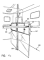
- FIG. 1 shows a holder 20 with a first guide 21, a second guide 22 and a third guide 23.
- the second guide 22 leads around a tongue which forms a stop 24 to an end portion 25 of the second guide 22.
- the first guide 21 and the third guide 23 have the same shape as the second guide 22 and accordingly also each have a stopper 24 and an end portion 25.
- a box bar 40 has a first end 41 (the other end) located in the end portion of the first guide 21 is located.
- the holder 20 also has a first plane 26 and a second plane 27.
- the first plane 26 has the guides 21, 22 and 23 and is offset from the second plane 27, d. H. between the first plane 26 and the second plane 27 or the wall of a horse transporter, a cavity 29 is formed. This serves to receive a rear part 42 of the first end 41 of the box bar 40.
- the guides 21, 22 and 23 are predominantly arcuate, so a good sliding of the first end 41 through the guides 21, 22 or 23 is possible and tilting of the first end 41 of the speaker bar 40 is avoided as possible.
- the stop 24 prevents the box bar 40 from slipping out of the corresponding guide or out of the holder. In such a stress, the box bar 40 could hit at most against the stop 24, but not slip out of the respective guide 21, 22 or 23.
- FIG. 2 shows the box bar 40 with the first end 41 before the first end 41 is inserted into the third guide 23 of the holder 20.
- the first end 41 of the box bar 40 is formed bolt-shaped and has a taper 43.
- the bolt has a rear part 42, which lies behind the taper 43 and a front part 44, which lies in front of the taper 43, on.
- the rear part 42 is in the cavity 29 between the first level 26 and second level 27 (see also FIG. 1 ).
- the taper 43 is in the guide 23 and the front part 44 of the first end 41 is located in front of the first plane 26.
- the box bar 40 when it is in the guide 23, can not be moved in the direction of the longitudinal axis of the box bar 40, but only along the guide 23.
- the box bar 40 For receiving the rear part 42 in the cavity 29 is at an initial portion 30th the third guide 23 (and also the first guide 21 and the second guide 22) a widening provided so that the rear part 42 can be received in the cavity 29.
- FIG. 3 shows a second bracket 60 having a first bracket ring 61, a second bracket ring 62 and a third bracket ring 63.
- the second bracket 60 is attached to a horse transporter 70 (see FIG FIG. 4 ) attached.
- a second end 45 (one end) of the speaker bar 40 is substantially U-shaped, with the U having different lengths of leg so that the second end 45 is hooked into the first ring 61 and second ring 62 or third ring 63, respectively can be.
- the first ring 61 is preferably opposite the end portion of the first guide 21, the second ring 62 is preferably opposite the end portion of the second guide 22, and the third ring 63 is preferably opposite the end portion of the third guide 23 FIG.
- the box bar 40 hangs down so that the box is in an open condition. Moving the first end 41 of the speaker bar 40 to the first guide 21 of the holder 20 would not release the connection of the second end 45 with the first ring 61. For this purpose, a movement of the rod 40 in the longitudinal direction upwards would be required.
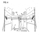
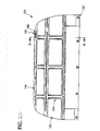
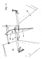
- FIG. 4 shows the interior of a horse transporter with a mounting system according to the invention.
- the box bar 40 is hooked with its second end 45 in the first ring 61 of the second holder 60.
- the first end 41 is located in the end position or in the end region 25 of the first guide 21.
- the second end 45 can not be released from the first ring 61, without first the first end 41 from the holder 20 and from the first guide 21 to solve.
- An unintentional slipping out of the first end 41 of the guide 21 is prevented by an existing stop 24 on the bracket 20.
- the size of the box can be changed by hanging the box bar 40 in another ring or guide. Depending on the inclination of the brackets and depending on the distance of the Guides or rings, the resulting size of the box can be defined.
- An angular range of about 30 to 60 degrees and a distance between the end portions of the guides of about 4 to 15 cm have been found to be advantageous for horse transporters.
- FIG. 5 shows an example of a side view of a horse transporter 100.
- FIG. 5 two screw members 125, 126 for fixing receptacles 118, 119, which are also in the FIG. 6 can be seen.
- screw 125, 126 other fasteners may be used, such as rivet, since the receptacles 118, 119 need not necessarily be easily solved.
- the eyebolts 116, 117 should be relatively easily solved, so that the brackets 101, 102 can be solved in an emergency by loosening the eye bolts 116, 117 of the wall 104 and, for example, fall to the bottom of the horse transporter 100.
- FIG. 6 shows a view of some elements of the horse transporter 100 obliquely from behind.
- the brackets 101, 102 are attached on the inner surface 103 of the outer wall 104.
- the brackets 101, 102 are brackets for a box bar 105, 106 of the horse transporter 100, which are secured by means of the receptacles 118, 119 and the eyebolts 116, 117 on the inner surface 103 of the outer wall 104.
- the receptacle 118 is adapted to receive a first end 120 of the support 101 and a second end 122 of the support 101 is fixed to the wall 104 by means of the eyebolt 117.
- the receptacle 119 is adapted to receive a first end 121 of the holder 102, wherein a second end 123 of the holder 102 is fixed by means of the eyebolt 116 to the wall 104.
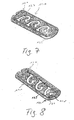
- FIGS. 7 and 8 show the holder 101 in more detail.
- FIG. 7 is a plan view of the side of the bracket 101, which faces away from the wall 104 in the installation
- FIG. 8 shows a plan view of one side of the holder 101, which faces the outer wall 104 in the installation.
- the bracket 101 has guides 127 which correspond to the guides already described above.
- an element 128 is arranged with a screw opening 130.
- the screw hole 130 acts with the eyebolt 117 for securing the second end 122 of the bracket 101 to the inner surface 103 together.
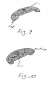
- FIGS. 9 and 10 show two views of the receptacle 118.
- FIG. 9 shows a plan view of a side of the receptacle 118, which faces away from the side wall 104 in the installation
- FIG. 10 shows a plan view of a side of the receptacle 118, which faces in the installation of the side wall 103.
- the receptacle 118 has a central screw opening 131 which cooperates with the screw 126 for attaching the receptacle 118 to the inner surface 103 of the side wall 104.
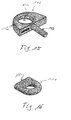
- the holder 102 is in the FIGS. 11 and 12 shown.
- FIG. 11 shows a plan view of a side of the holder 102, which faces in the installed state of the side wall 104
- FIG. 12 shows a plan view of one side of the holder 102, which faces away in the installed state of the side wall 104.
- the bracket 102 has two guides 132 connecting a start portion 133 for receiving one end of the speaker bar to an end portion 134 for locking the end of the speaker bar. Between the starting portion 133 and the end portion 134, a stopper 135 is provided to prevent unintentional detachment of the end of the box bar from the end portion 143.
- the guide 132 therefore has a substantially curved region and a subsequent linear region forming the end region.
- an element 137 is provided with a screw opening 136.
- the element 137 is arranged in a corner region of the recess 138 at the second end 123 of the holder 102.
- the screw hole 136 cooperates with the eyebolt 116 to secure the second end 123 of the bracket 102 to the inner surface 103 of the side wall 104.
- FIGS. 13 and 14 11 show views of the receptacle 119 for receiving the first end 121 of the holder 101.
- the receptacle 119 has a screw opening 139 which is adapted to cooperate with the screw element 125 for fastening the receptacle 119 to the inner surface 103 of the outer wall 104.
- the receptacle 119 on a Anbindering 124 for tethering a horse.
- FIG. 15 shows the screw 116 with a bolt 140 and a ring member 141.
- a stick or stick can be performed, especially in an emergency situation the eyebolt 116 to solve quickly.
- the further eyebolt 117 is preferably similar, in particular designed the same as in FIG. 15 shown eyebolt 116th
- brackets 101, 102 for holding a first end 112, 144 of the speaker bar 105, 106 may be considered as first brackets.
- the second ends 111, 143 of the box bar 105, 106 are held with second brackets 110, 113 on a partition wall 108.
- the divider wall is disposed between the side wall 104, which may be referred to as a first side wall, and an opposing second side wall 109 for separating two horses from each other.
- the second holders 110, 113 have ring elements 114, 115 for receiving the second end 111, 143 of the box bar 105, 106.
- the ring elements 114 of the second holder 110 extend obliquely to the horizontal and are arranged on a planar strut 145.
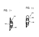
- One of these ring elements 114 is in FIG. 16 shown.
- the ring member 114 has a planar side surface 146 which is welded to the planar strut 145.
- the holder 110 has three ring elements 114, which are arranged at different heights, which correspond to the heights of the guides, in particular of the end regions of the guides, of the first holder 101.
- the ring elements 115 of the second holder 113 are arranged substantially along a vertical, wherein the heights of at least two ring elements 115 correspond to the heights of the guides, in particular of the end regions of the guides, of the holder 102.
- the arrangement of the ring elements and the guides at different heights makes it possible to keep the respective box bar at a height which corresponds to the size of each horse to be transported.
- the ring elements 115 of the second holder 113 are preferably fastened to a tubular element 147 of the partition wall 108.
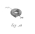
- One of these ring elements 115 is in FIG. 17 shown.
- the ring element 115 has a rounded outer surface 148, which is welded to the tubular element 147.
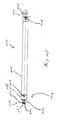
- FIG. 18 shows an example of an embodiment of the box bar 105.
- the first end 112 of the box bar 105 has a box bar end piece 153 with a slot bolt 157 on.
- the groove bolt 157 comprises a guide groove 152 between two axially spaced-apart extensions 150, 151 of the groove bolt 157.
- the extensions 150, 151 are preferably circular.
- the diameter of the groove bolt in the region of the guide groove 152 is preferably smaller than the diameter outside the guide groove 152.
- the guide groove 152 is adapted, for example, in the guides 127 of the holder 101 to be performed.
- the box pole end piece 153 also has a fastening sleeve 158, which is connected via a fastening means 154 to the speaker bar.
- the fastening means 154 is for example a fastening screw or a fastening rivet.
- the box bar 105 also has a coating tube 155, which is preferably pulled over an inner tube of the speaker bar.
- the second end 111 of the speaker bar 105 includes a hook end 156 for hooking into the ring members 114. Also, the hook end 156 is preferably connected to the speaker bar via a fastener 159 such as a mounting bolt or a mounting rivet.
- first and second brackets may for example be mounted vertically, horizontally and / or diagonally, in particular at an angle of 45 degrees to the horizontal, in the horse transporter.
- first brackets could be attached to a partition.
- the second brackets could also be attached to an outer wall.
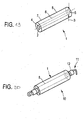
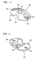
- FIG. 19 shows a retrofittable padding 1 for padding a box pole for use in an animal transporter.
- the retrofittable padding 1 has a through hole 2 and is tubular.
- the retrofittable padding consists of a soft-elastic foam, which has a stretching property.
- a diameter 3 of the padding 1 is smaller than the diameter of a speaker bar, over which the retrofittable padding is slipped. When slipping over the padding, the hole 2 expands and thus presses against the speaker bar. The slipping over the speaker bar is done by a first opening 4 or a second opening 5 of the retrofittable padding 1.
- An inside 6 of the retrofittable padding preferably has a non-slip layer, so that slipping of the padding of the speaker bar in the longitudinal direction or in the radial direction difficult becomes.
- An outer side 7 of the padding 1 is preferably provided with a protective cover 8, which protects the padding and has a soft, hand-flattering outer side.
- the envelope 8 also acts as a kind of cover which can be replaced and
- FIG. 20 shows a box bar 11 with a retrofittable padding 1.
- the retrofittable padding 1 consists essentially of a stretchable foam part and can therefore be placed well over the box bar 11.
- the soft elastic extensible Foam is non-slip connected by these properties even with uneven outer sides 12 of the box bar 11.
- the retrofittable padding can be pulled over a box bar 11, which in turn already has a padding.
- the retrofittable padding 1 thus represents an easy way to subsequently improve the cushioning properties of an existing speaker bar.
- the box bar 11 can be hung in an animal transporter, in particular a horse transporter, for example a horse trailer, and thus delimits a box containing, for example, a horse or another animal.
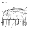
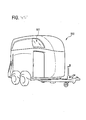
- FIG. 21 2 shows by way of example an animal transporter 630 with a tarpaulin 631 for covering a rear upper opening 632.
- the tarpaulin 631 has an air-impermeable region 633 and an air-permeable mesh area, which in FIG. 21 can not be seen and is described in more detail below.
- the tarpaulin 631 is a tarpaulin lift, that is, in this embodiment, the tarpaulin 631 is provided with leaf springs which extend in vertical pockets 634 of the tarpaulin 631.
- the leaf springs are formed so that they endeavor to unroll and thus the tarpaulin 631, so that the rear upper opening 632 is released.
- the tarpaulin further includes a tarpaulin 638 for covering the air-permeable mesh area.
- the tarpaulin 638 and the tarpaulin 631 are formed so that the tarpaulin 638 is changeable between a first state and a second state, wherein in the first state in this embodiment, the net area is completely covered and in the second state in this embodiment the net area is not is covered.
- the first state is shown.
- the tarpaulin 631 and the tarpaulin 638 have retaining means 639, 640, in particular hook-and-loop fasteners, in order to hold the tarpaulin 638 in the second state.
- the holding means 639 of the tarpaulin 638 are arranged to run along the lower outer edge of the tarpaulin 638 when the tarpaulin 638 is in the first state, that is, when the tarpaulin 638 covers the net area.
- the holding means 640 are arranged on the tarpaulin 631 such that, when the tarpaulin 638 is folded up to release the net area in the second state, they cooperate with the holding means 639 of the tarpaulin 638 to hold the tarpaulin 638 in the second state.
- This second state is exemplary in FIG. 22 shown.
- the tarpaulin 638 As shown in the in FIG. 22 As shown in the second state, the tarpaulin 638 has released the mesh area 643, this mesh area 643 is in the FIG. 22 to recognize. Furthermore, in the FIG. 22 Retaining means 641, 642, in particular Velcro, can be seen, the tarpaulin 638 in the in FIG. 21 can keep shown first state. It is also possible to fasten the tarpaulin 638 by means of the holding means 641, 642 such that the net area 643 is covered to a desired proportion, for example to 650 percent.
- the holding means 641 of the tarpaulin 631 extend vertically on the impermeable region 633 adjacent to the mesh region 643, and the holding means 642 of the tarpaulin 638 extend vertically in the first state or in the second state at the edge of the tarpaulin 638 such that in the closed first state the holding means 641 , 642 can cooperate to hold the tarpaulin 638 in this first state.
- FIG. 23 11 shows by way of example the animal transporter 630 in a state in which the tarpaulin 631 has been rolled up by means of the leaf springs, so that the rear opening 632 of the animal transporter 630 is released.
- FIG. 24 shows by way of example a further embodiment of a tarpaulin 131 with a tarpaulin 138.
- the tarpaulin 131 and the tarpaulin 138 have holding means 139, 140, in particular Velcro fasteners, which arranged in the solid state of the tarpaulin 131 and the first state of the tarpaulin 138 substantially horizontally are and can hold the tarpaulin 138 in a second state on the tarpaulin 131.
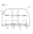
- FIG. 25 shows an example of a plan view of the after installation in the animal transporter from the inside to be seen side of the tarpaulin 131.
- the tarpaulin 131 has vertical pockets 134, in which leaf springs for automatic rolling up of the tarpaulin 131 are arranged. Furthermore, the tarpaulin 131 horizontal pockets 144, in which reinforcing struts 145 are arranged with Kochsteckkappen 146.
- the uppermost reinforcing strut 145 is preferably fastened, in particular riveted or screwed, to the upper edge of the rear upper opening of the animal transporter, that is to say in particular at the upper edge of the hood of the animal transporter.
- the tarpaulin 131 further comprises at its lower edge eyelets 147, where, for example, in FIG. 21 shown loops 35 can be attached.
- FIG. 26 shows a sectional view taken along the line AA in FIG. 25 , In the FIG. 26 Y and Z designated areas are in the FIG. 26 and 14 shown enlarged.
- FIG. 26 It can be seen that the lower reinforcement strut 145 is disposed in the lower horizontal pocket 144 and fixed by means of a rivet 149, in particular a hollow rivet.
- FIG. 28 It can be seen that the uppermost reinforcing strut 145 is also fixed within the uppermost horizontal pocket 144 by means of a rivet 149, in particular a hollow rivet.
- the same or different reinforcing struts 145 can be arranged, which can be fixed in the same or different manner, in particular with the same or different rivets, in the respective horizontal pocket 144.
- the top and bottom reinforcing struts are preferably struts with a rectangular profile, while the intermediate reinforcing strut preferably has a round profile.
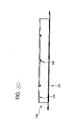
- FIG. 29 shows the side of the tarpaulin 131, which can be seen from the outside after attachment to the animal transporter.
- Holding means 139 which are attached to the tarpaulin 138
- holding means 140 which are attached to the tarpaulin 131, to recognize.
- These retaining means 139, 140 are preferably Velcro fasteners.
- Eyelets 148 can be seen, which are arranged on the lower edge of the tarpaulin 138. Through these eyelets 148, for example, in FIG. 21 shown and attachable to the eyelets 147 of the tarpaulin 131 loops 35 are passed when the tarpaulin 138 completely covers the air-impermeable network area, that is folded down, and the tarpaulin 131 is held in the fully pulled down state by means of loops 35.
- FIG. 30 shows by way of example a plan view of the tarpaulin 131, in which FIG. 24 shown state. Also the FIGS. 25 to 29 show the tarpaulin 131 in the in FIG. 24 shown state.
- top view is the slightly folded forward and upward tarpaulin 138 with the holding means 139 and the eyelets 148 can be seen.
- the impermeable portion of the tarpaulin is preferably made of PVC material, such as available from Sioen Industries. This is preferably a material which is classically used for truck tarpaulins.
- the air-permeable mesh area is preferably formed by an open-pored net, which is preferably a product of Huesker Synthetic GmbH. This material is also described in detail in the DLG Test Report 4882. Preferably, the material has at least one open porosity of about 30% or more in order to achieve sufficient aeration.
- FIG. 4 shows an animal transporter with a partition 200, wherein a rod 201 of the partition 200 is connected at an attachment point with a bottom member 202.
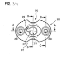
- FIG. 31 shows by way of example an enlarged view of a rod 201 of a partition, which is connected to the bottom member 202, that is a bottom plate, by means of a fastener 203.
- the fastener 203 is a member for securing a rod 201 of a partition to a floor member 202 of an animal carrier.
- the fastener 203 is in a plan view and in a view from below in the FIGS. 32 and 33 exemplified.
- the fixing member 203 has a bottom connecting portion 204 for connecting the fixing member 203 to the bottom member and a rod connecting portion 205 for connecting the fixing member 203 to the rod.
- the ground connection area 204 comprises at least two connection openings 206 for performing connection means for connecting the fastening element 203 to the floor element. These connection openings 206 serve to fasten the fastening element 203 to the floor element, in particular by means of screws or other securing means that can be carried out.
- the bar connecting portion 205 has a lock hole 207 for receiving a lock member of the bar for making a lock connection.
- the lock opening 207 has a circular area 212 and a substantially rectangular area 212 adjoining the circular area 211, a line from the center of the circular area 211 to the center of the rectangular area 212 having a non-zero angle with one of the two communication openings 206 connecting line includes.
- the circular area 211 and the rectangular area 212 are particularly explained in more detail below Figures 34 and 38 shown.
- substantially the side of the fastener 203 is shown which, when fastened to the floor element, substantially faces the pole.
- This rod side 208 is rounded.
- the fastener 203 is adapted to form a cavity with the floor member in the condition connected to the floor member into which the locking member is insertable through the latch opening 207 for securing the rod.
- the fastening element 203 has lateral cleaning openings 210, which allow a cleaning of the cavity. In addition, the cleaning openings 210 lead to material and cost savings.
- FIG. 33 is a plan view of the bottom side 209 of the fastener 203 shown, which rests in the attached state to the bottom element.
- FIG. 34 shows an example of a plan view of the rod side of the fastener 203 and the FIGS. 35 to 37 show sectional views along the in FIG. 34 shown lines CC, BB and AA.
- Figure 38 shows a plan view of the bottom side 219 of the fastener 203rd
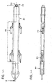
- FIG. 39 shows by way of example a perspective view of a rod 301, in particular a partition, which is connected to a bottom element of an animal carrier by means of a fastening element is connectable.
- the rod 301 has bolts 313, four bolts 313 in this embodiment.
- the bolts for example, transverse struts of a partition wall or box bars can be connected to the bar 301.
- 314 is in FIG. 39 the side facing the bottom element in the installed state.
- FIG. 40 shows a further view of the rod 301.
- the rod 301 is a tube which has a locking element 315 with a securing pin on its in the installed state the bottom element facing side 314.
- FIG. 41 shows a view of the rod 301 along the in FIG. 40 with XX designated line.
- Figure 42 shows a plan view of the bottom member in the installed state facing side 314 of the rod 301.
- the securing pin of the locking member 315 includes with a transverse line that connects two arranged at the same height bolt, a non-zero angle. This angle is preferably 15 degrees.
- the locking element 315 with the securing pin can cooperate with the locking opening 207 of the fastening element 203 in order to easily fix the rod 301 to the floor element by means of the fastening element 203 and also to release it again easily by unlocking.
- the fastener may be used to connect partitions of different types within an animal carrier to a bottom member of the animal carrier.
- the partition wall may, for example, have a substantially U-shaped bent bar, wherein the two ends of the substantially U-shaped bent bar are connected to the bottom element.
- at least one of these ends is connected by means of the fastening element with the bottom element.
- One of these ends therefore preferably comprises a locking element which cooperates with a locking opening of the fastening element which is fastened to the floor element in order to lock the rod of the separating wall and thus the separating wall to the fastening element, so that the separating wall is fastened to the floor element ,
- FIG. 43 One type of partition, which according to the invention can be connected by means of a fastening element to a bottom element of an animal carrier, is shown by way of example in FIG FIG. 43 shown.
- FIG. 43 shows the interior of an animal transporter, in particular a horse trailer, with a partition wall 300.
- the partition wall 300 has a central rod 301 which is fastened by means of the fastening element 203 to the bottom element 302.
- Partition elements 317 are attached to the rod 301 by means of the bolts 313.
- the partition wall elements 317 furthermore have ring elements 318 with which the partition wall elements 317 can be connected, for example by means of box poles 316, to side walls of the animal transporter.
- two partition wall elements 317 are connected by means of bolts 313 on the middle bar 301 and also by means of two box bars 316 to the side walls of the animal transporter.
- the center bar 301 extends from the floor member 302 to the corner of the animal carrier to which the bar 301 is also fixed, preferably screwed.
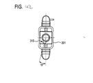
- FIG. 44 Another partition, which according to the invention can be fastened to a base element by means of a fastening means, is exemplary in FIG FIG. 44 shown.
- the partition wall 400 has a frame formed by rods 419, which encloses a partition plate 420 made of plastic or wood, for example.
- the dividing wall 400 is connected to the bottom element 402 of the animal transporter by means of a rod 401 and a fastening element according to the invention.
- the partition wall 400 further includes ring members 421 which are particularly secured to the frame 419 of the divider 400 and which are engageable with corresponding protrusions of box poles 416 to connect the divider wall 400 to the side panels 422 of the animal carrier via the box poles 416.
- the ring members 421 and the box bars 416 are arranged so that both a front end of the partition wall 400 and a rear end of the partition wall 400 are connected to both side walls 422, respectively.
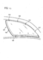
- FIG. 45 shows by way of example an animal transporter 500 with a Ausstellpper 501.
- An enlarged external view of the Ausstellromes 501 is exemplary in FIG. 46 shown.
- an interior view of the Ausstellppers 501 is exemplary in FIG. 47 shown.
- the pop-up window 501 covers a front side opening 502 of the animal carrier 500.
- the opening 502 has a curved front first side 504 that faces the direction of travel, a second side 505 that faces away from the direction of travel, and a lower third side 506 that defines the opening 502 downward.
- the pop-up window 501 has corresponding sides facing the respective sides of the opening 502 in the closed state.
- the first page 504 extends from one front corner of the opening 502 upwardly and rearwardly to a rear upper corner of the opening 502. This entire side 504 is considered as the direction of travel facing side.
- the second side 505 extends with a slight outer arc from the rear upper corner to a rear lower corner, and the side 506 extends substantially horizontally from the rear lower corner to the front lower corner.
- the opening 502 and thus the corresponding Ausstellari 501 thus have the shape of a distorted triangle.
- the opening window and the corresponding opening may also have at least one further side and, for example, the shape of a quadrilateral.
- the opening 502 is penetrated by horizontal struts 503 in order to stabilize the animal transporter in this area.
- FIG. 49 shows by way of example the opening 502 with the Ausstellpper 501 in an open state in an outside view and FIG. 50 shows an example of the opening 502 with the Ausstellpper 501 in an interior view.
- FIG. 49 It can be seen that the edge of the opening 502 is provided with a window frame 511.
- the window frame 511 can be riveted, screwed or glued to the edge of the opening 502, for example. Furthermore, in FIG. 49 it can be seen that the window frame 511 has an insulating rubber 512 running along the window frame.
- the first side 504 of the opening 502 facing side of the Ausstellromes 501 is connected to the corresponding side of the window frame 511 by means of cylindrical rubber elements.
- One of these rubber elements 507 is exemplified in FIG. 48 shown.
- the rubber element is cylindrical, wherein at opposite ends of the rubber element 507 screw 508 for screwing the rubber element with the window frame 511 and the Ausstellari 501 are present. That is, for connecting the side of the window frame 511 facing the first side of the opening 502, a plurality of rubber members 507 are screwed along this side of the window frame 511.
- the respective opposite end of the rubber element 507 is screwed to the corresponding side of the Ausstellwitppers 501.
- this screw connection takes place at least at the three connection points 513, which in FIG. 46 are shown.
- a handle 509 is mounted substantially centrally on the lower side of the opening window 501.
- the handle 509 may be bolted or glued to the hinged window 501, for example.
- the handle 509 is connected by means of a leaf spring 510 to the opening 502, in particular to the third side 506 of the opening 502.
- the leaf spring 510 is pivotally connected to the opening 502.
- the leaf spring 501 may be a continuous leaf spring guided by the handle, or two-leaf springs 510 may be provided, each connecting one end of the handle 509 to the opening 502.
- the leaf spring 510 is formed to be in the in the Figures 46 and 47 shown closed state holds the Ausstellaris 501 in the closed state, wherein the opening of the Ausstellromes 501 is pressed against a spring resistance by means of the handle 509 from the inside against the Ausstellrous 501 until a dead center of the leaf spring 510 is exceeded and the spring force of the leaf spring 510 the Ausstellrous 501 opens and in particular in the Figures 49 and 50 shown opened state.
- animal transporters have certain features, these animal transporters may also have more or less inventive features.
- an animal transporter may have all the features disclosed, in particular in the claims.
- Features described in the above-mentioned embodiments as belonging to different animal transporters may also be realized in a single animal transporter.
- the invention relates to a holder of an attached at one end of the box bar for an animal transporter, in particular a horse transporter, with a guide for another end of the speaker bar, wherein the guide is formed so that the other end can engage in the guide, wherein the Guide connecting a starting portion for receiving the other end with an end portion for locking the other end, wherein between the input portion and the end portion, a stop for preventing accidental detachment of the other end is formed from the end portion.
Description
Die Erfindung betrifft eine Halterung einer Boxenstange für einen Tiertransporter, insbesondere in einem Pferdetransporter. Weiterhin betrifft die Erfindung eine Boxenstange, ein Halterungssystem für eine Boxenstange sowie einen Tiertransporter, insbesondere einen Pferdetransporter.The invention relates to a holder of a speaker bar for an animal transporter, in particular in a horse transporter. Furthermore, the invention relates to a speaker bar, a support system for a speaker bar and an animal transporter, in particular a horse transporter.
Boxenstangen für Tiertransporter sind beispielsweise aus der
Derartige Boxenstangen können aus einem harten Material, wie beispielsweise einem Metall, bestehen. Es ist wünschenswert, das in einem Tiertransporter zu transportierende Tier, insbesondere Pferd, vor Druckbelastungen und vor Verletzungsgefahren zu schützen. Druckbelastungen entstehen beispielsweise im Brustbereich des Pferdes, wenn dieses gegen eine Boxenstange stößt.Such box bars may be made of a hard material such as a metal. It is desirable to protect the animal, in particular horse, to be transported in an animal transport vehicle from pressure loads and from risk of injury. Pressure loads arise, for example, in the chest area of the horse, when this bumps against a speaker bar.
Derartige Boxenstangen werden in der Regel an einer Halterung für die Boxenstange lösbar befestigt. Beispielsweise wird ein Ende einer Boxenstange in eine erste Halterung und das andere Ende einer Boxenstange in eine zweite Halterung gemäß einem Haltemechanismus der Boxenstange befestigt. Die beiden Halterungen sind häufig im Inneren eines Tiertransporters, insbesondere eines Pferdetransporters, angeordnet, und die Boxenstange wird an diesen Halterungen befestigt, um eine Box, beispielsweise eine Pferdebox, zu begrenzen.Such box poles are usually releasably attached to a holder for the speaker bar. For example, one end of a speaker bar is fixed in a first holder and the other end of a speaker bar is mounted in a second holder in accordance with a holding mechanism of the speaker bar. The two brackets are often located inside an animal transporter, particularly a horse transporter, and the box bar is attached to these brackets to confine a box, such as a horse box.
Es ist Aufgabe der vorliegenden Erfindung eine Halterung für eine Boxenstange vorzusehen, an der eine Boxenstange auf angenehme Weise befestigt werden kann.It is an object of the present invention to provide a holder for a speaker bar, to which a speaker bar can be fastened in a pleasant manner.
Eine weitere oder alternative Aufgabe ist es, die Flexibilität eines Tiertransporters, insbesondere eines Pferdetransporters, zu erhöhen.Another or alternative object is to increase the flexibility of an animal carrier, in particular a horse transporter.
Es ist eine weitere oder alternative Aufgabe der vorliegenden Erfindung, eine Vorrichtung vorzusehen, die ein Tier, insbesondere ein Pferd, beim Transport vor Verletzungen schützt und/oder Druckbelastungen des Tieres mindert.It is a further or alternative object of the present invention to provide a device which protects an animal, in particular a horse, from injury during transport and / or reduces pressure loads on the animal.
Somit wird erfindungsgemäß eine Halterung einer an einem Ende eingehängten Boxenstange für einen Tiertransporter, insbesondere einen Pferdetransporter, vorgesehen. Die Halterung weist eine Führung des anderen Endes der Boxenstange auf, deren anderes Ende in die Führung eingreift. Die Führung verbindet einen Anfangsbereich zum Aufnehmen des anderen Endes mit einem Endbereich zum Arretieren des anderen Endes. Zwischen dem Anfangsbereich und dem Endbereich bildet die Führung einen Anschlag zum Verhindern eines ungewollten Herauslösens des anderen Endes aus dem Endbereich.Thus, according to the invention a holder of an attached at one end of the box bar for an animal transporter, in particular a horse transporter provided. The holder has a guide of the other end of the speaker bar, the other end engages the guide. The guide connects a start portion for receiving the other end to an end portion for locking the other end. Between the starting portion and the end portion, the guide forms a stop for preventing accidental detachment of the other end from the end portion.
Somit wird ein einfaches Aufnehmen des anderen Endes einer Boxenstange erreicht und gleichzeitig wird die Boxenstange in ihrer Endposition, d. h. wenn sie sich im Endbereich befindet, gegen ein Rausrutschen bzw. Herauslösen gesichert. Denn durch Vibrationen oder durch ein Schlagen des Tieres gegen die Boxenstange kann das andere Ende der Boxenstange nur gegen den Anschlag springen und nicht über den Anschlag hinweg und aus der Führung heraus.Thus, a simple recording of the other end of a speaker bar is achieved and at the same time the speaker bar is in its final position, i. H. if it is in the end area, secured against slipping or detachment. Because by vibration or by hitting the animal against the pit bar, the other end of the pit bar can only jump against the stop and not over the stop and out of the guide.
Die Halterung kann beispielsweise an einem Tiertransporter, insbesondere an einem Pferdetransporteur, befestigt sein. Für die Befestigung der Halterung sind beispielsweise Nieten geeignet. Das andere Ende der Boxenstange ist beispielsweise bolzenförmig ausgebildet. Bei der Führung kann es sich beispielsweise um einer Aussparung in einer Platte, bevorzugt Metallplatte, handeln, die bevorzugt eine schmale, längliche Form aufweist und einen Weg um eine Zunge beschreibt. Bevorzugt bildet die Zunge dann den Anschlag. Der Anfangsbereich bzw. Eingangsbereich der Führung dient der Aufnahmen des anderen Endes, beispielsweise des bolzenförmigen Endes einer Boxenstange und zum Führen hin zu einem Endbereich. Der Endbereich der Führung definiert dann den Endsitz bzw. die Endposition des anderen Endes der Boxenstange. Das andere Ende der Boxenstange kann beispielsweise als ein Stift oder ein Bolzen ausgebildet sein.The holder may for example be attached to an animal transporter, in particular to a horse transporter. For example, rivets are suitable for fastening the holder. For example, the other end of the speaker bar is bolt-shaped educated. The guide can be, for example, a recess in a plate, preferably a metal plate, which preferably has a narrow, oblong shape and describes a path around a tongue. Preferably, the tongue then forms the stop. The starting area or entrance area of the guide serves to receive the other end, for example the bolt-shaped end of a box bar and to guide it to an end area. The end portion of the guide then defines the end seat or end position of the other end of the speaker bar. The other end of the speaker bar may be formed, for example, as a pin or a bolt.
Die Ausbildung des Anschlags zwischen dem Anfangsbereich und dem Endbereich der Führung kann beispielsweise bedeuten, dass der Anschlag auf oder an dem Weg, den die Führung beschreibt, ausgebildet ist. Beispielsweise kann als Anschlag ein Abschnitt einer Wandung, die die Führung zumindest teilweise definiert verwendet werden.The formation of the stop between the starting region and the end region of the guide can mean, for example, that the stop is formed on or on the path which the guide describes. For example, can be used as a stop, a portion of a wall that defines the guide at least partially defined.
Gemäß einer Weiterbildung der Erfindung weist die Halterung eine Mehrzahl von den Führungen auf, bevorzugt drei Führungen, die nebeneinander in einer ersten Ebene angeordnet sind. In einer weiteren Weiterbildung der Erfindung weist die Halterung eine Mehrzahl von den Führungen auf, bevorzugt drei Führungen, die übereinander angeordnet sind.According to one embodiment of the invention, the holder has a plurality of the guides, preferably three guides, which are arranged side by side in a first plane. In a further development of the invention, the holder has a plurality of the guides, preferably three guides, which are arranged one above the other.
Ein Anordnen der Mehrzahl von Führungen nebeneinander bedeutet auch, dass die Endbereiche der Führungen nebeneinander angeordnet, was zu verschiedenen Endpositionen des anderen Endes einer Boxenstange führt, wenn diese in eine andere benachbarte Führung eingesetzt wird. Die Größe einer mit einer derartigen Boxenstange begrenzten Box kann somit verändert werden. Insbesondere drei unterschiedliche Boxengrößen sind für Pferdetransporter gut geeignet. Abhängig von der Positionierung der erfindungsgemäßen Halterung mit der Mehrzahl von Führungen kann eine gewünschte Größenveränderlichkeit der Box bestimmt werden. Die Box ist beispielsweise nur in der Höhe verstellbar, wenn die Endbereiche der Führungen senkrecht übereinander an einem Tiertransporter angeordnet sind. Die Box ist beispielsweise nur in der Länge verstellbar, wenn die Endbereiche der Führungen horizontal nebeneinander an einem Tiertransporter angeordnet sind. Bevorzugt wird die Halterung mit einer Mehrzahl von Führungen derart an einem Tiertransporter angeordnet, dass Boxen unterschiedlicher Höhe und Länge gebildet werden können. Dazu sind beispielsweise die Endbereiche der Führungen der Halterung an einer innenliegenden Seitenwand des Tiertransporters an unterschiedlichen Höhen vom Boden aus und in einer horizontalen Richtung nebeneinander angeordnet.Placing the plurality of guides side by side also means that the end portions of the guides are juxtaposed, resulting in different end positions of the other end of a speaker bar when inserted into another adjacent guide. The size of a limited with such a speaker bar box can thus be changed. In particular, three different box sizes are well suited for horse transporters. Depending on the positioning of the holder according to the invention with the plurality of guides, a desired dimensional variability of the box can be determined. For example, the box can only be adjusted in height if the end regions of the guides are arranged vertically one above the other on an animal transporter. For example, the box can only be adjusted in length if the end regions of the guides are arranged horizontally next to one another on an animal transporter. Preferably, the holder is arranged with a plurality of guides on an animal transporter such that boxes of different height and length can be formed. For this purpose, for example, the end portions of the guides of the holder on an inner side wall of the animal transporter different heights from the ground and arranged side by side in a horizontal direction.
Gemäß einem weiteren Aspekt der Erfindung ist die Führung zumindest teilweise bogenförmig ausgebildet. Eine bogenförmige Ausbildung der Führung führt zu einem einfachen Gleiten des anderen Endes einer Boxenstange durch die Führung. Ein ungewolltes Verhaken des anderen Endes in der Führung wird so vermieden oder zumindest verringert.According to a further aspect of the invention, the guide is at least partially arcuate. An arcuate design of the guide results in a simple sliding of the other end of a speaker bar through the guide. Unintentional hooking of the other end in the guide is thus avoided or at least reduced.
Gemäß einem weiteren Aspekt der Erfindung weist die Halterung eine erste Ebene, in der die wenigstens eine Führung angeordnet ist und eine zweite Ebene, in der Befestigungsmittel zum Befestigen der Halterung, beispielsweise an einem Tiertransporter, insbesondere an einem Pferdetransporter, angeordnet sind, wobei die erste Ebene und die zweite Ebene parallel und voneinander beabstandet sind.According to a further aspect of the invention, the holder has a first plane, in which the at least one guide is arranged, and a second plane, in which fastening means for fastening the holder, for example on an animal transporter, in particular on a horse transporter, are arranged, wherein the first Level and the second level are parallel and spaced from each other.
Die zweite Ebene weist beispielsweise Bohrungen auf, mit der die Halterung beispielsweise an der Innenseite eines Tiertransporters befestigt werden kann. Hierfür sind beispielsweise Nieten oder Schrauben geeignet. Die zweite Ebene mit der wenigstens einen Führung ist von dieser Befestigungsebene abgesetzt, so dass sich zwischen der Wand eines Tiertransporters und der ersten Ebene ein Hohlraum bilden kann. Somit kann ein Teil des anderen Endes einer Boxenstange bzw. ein Teil eines Bolzens von diesem Hohlraum bzw. in den Raum zwischen der ersten Ebene und der zweiten Ebene aufgenommen werden.The second level, for example, has holes with which the holder can be attached, for example, to the inside of an animal carrier. For this example, rivets or screws are suitable. The second level with the at least one guide is offset from this mounting plane so that a cavity can form between the wall of an animal carrier and the first level. Thus, a part of the other end of a box bar or a part of a bolt can be received by this cavity or in the space between the first level and the second level.
Die Aufgabe wird auch gelöst mit einer Boxenstange zur Verwendung in einem Tiertransporter, insbesondere Pferdetransporter. Die Boxenstange weist ein Ende zum Einhängen an einem Tiertransporter und das anderes Ende zum Einführen in eine Führung einer erfindungsgemäßen Halterung auf.The object is also achieved with a box bar for use in an animal transporter, in particular horse transporter. The box bar has an end for hanging on an animal carrier and the other end for insertion into a guide of a holder according to the invention.
Das Einhängen stellt auch ein lösbares Befestigen dar. Das eine Ende der Boxenstange weist bevorzugt eine U-förmige Gestalt auf, wobei das U ungleichlange Schenkel besitzt. Dieses U-förmige Ende kann beispielsweise zum Befestigen durch einen Ring an einen Tiertransporter gesteckt werden.Hooking also provides releasable attachment. The one end of the box bar preferably has a U-shaped configuration with the U having unequal length legs. This U-shaped end can be plugged, for example, for attachment through a ring to an animal transporter.
Gemäß einer Weiterbildung der Erfindung ist das andere Ende ausgebildet, Bewegungen des anderen Endes entlang der Führung zu erlauben und Bewegungen des anderen Endes in Längsrichtung der Boxenstange zu verhindern. Somit wird die Position der Boxenstange besser definiert und ein ungewolltes Verrutschen wird verhindert. Dies wird beispielsweise dadurch erreicht, dass an dem anderen Ende der Boxenstange ein Abschnitt einen kleineren Querschnitt als die benachbarten Abschnitte aufweist, beziehungsweise dadurch, dass das andere Ende eine Verjüngung aufweist.According to one embodiment of the invention, the other end is designed to allow movements of the other end along the guide and movements of the other End to prevent in the longitudinal direction of the speaker bar. Thus, the position of the speaker bar is better defined and accidental slippage is prevented. This is achieved, for example, in that at the other end of the box bar a section has a smaller cross-section than the adjacent sections, or in that the other end has a taper.
Die Aufgabe wird auch gelöst mit einem Halterungssystem für eine Boxenstange zur Verwendung in einem Tiertransporter, insbesondere in einem Pferdetransporter. Das Halterungssystem weist eine erfindungsgemäße Halterung und eine zweite Halterung zum Aufnehmen des einen Endes der Boxenstange auf, wobei das Halterungssystem geeignet ist, ein Lösen des anderen Endes der Boxenstange von der zweiten Halterung nur bei einem gelösten anderen Ende zu ermöglichen.The object is also achieved with a holder system for a box bar for use in an animal transporter, in particular in a horse transporter. The mounting system includes a bracket according to the invention and a second bracket for receiving one end of the speaker bar, the bracket system being adapted to permit release of the other end of the speaker bar from the second bracket only when the other end is disengaged.
Befindet sich das eine Ende der Boxenstange in der zweiten Halterung und das andere Ende in der ersten Halterung, so kann das eine Ende der Boxenstange nicht aus der zweiten Halterung gelöst werden. Zunächst muss das andere Ende aus der Führung der ersten Halterung geschoben werden, damit eine entsprechende Bewegung der Boxenstange möglich ist, um diese auch von der zweiten Halterung zu lösen. Somit ist der sichere Halt einer Boxenstange verbessert. Die zweite Halterung liegt im Allgemeinen der ersten Halterung gegenüber. Wenn die erste Halterung mehrere Führungen aufweist, so weist die zweite Halterung ebenfalls mehrere Haltereinrichtungen, beispielsweise Ringe oder Ösen auf, die jeweils der Endposition der entsprechenden Führung gegenüber liegen.If one end of the speaker bar is in the second holder and the other end is in the first holder, then one end of the speaker bar can not be released from the second holder. First, the other end must be pushed out of the guide of the first holder, so that a corresponding movement of the speaker bar is possible in order to solve this also from the second holder. Thus, the secure grip of a speaker bar is improved. The second bracket is generally opposite the first bracket. If the first holder has a plurality of guides, then the second holder also has a plurality of holder devices, for example rings or eyelets, which respectively lie opposite the end position of the corresponding guide.
Die Aufgabe wird zudem gelöst durch ein Halterungssystem mit einer erfindungsgemäßen Halterung für eine Boxenstange eines Tiertransporters, insbesondere eines Pferdetransporters, und mindestens einem Befestigungsmittel zur Befestigung der Halterung an einer ersten Fläche einer Wand des Tiertransporters, wobei das Halterungssystem so angepasst ist, dass, wenn die Halterung an der ersten Fläche der Wand befestigt ist, durch Betätigen des Befestigungsmittels an einer zweiten Fläche der Wand, die der ersten Fläche gegenüberliegt, die Halterung von der ersten Fläche der Wand zumindest teilweise, insbesondere vollständig, gelöst werden kann. Die Wand des Tiertransporters ist bevorzugt eine seitliche Außenwand des Tiertransporters und/oder eine innere Wand des Tiertransporters, insbesondere eine innere Trennwand des Tiertransporters, die zwei Bereiche des Innenraums des Tiertransporters voneinander trennt, um beispielsweise zwei Pferde in dem Tiertransporter voneinander getrennt zu befördern. Wenn die Wand des Tiertransporters eine Außenwand ist, ist die erste Fläche der Außenwand bevorzugt die Innenfläche der Außenwand und die zweite Fläche der Außenwand ist bevorzugt die Außenfläche der Außenwand. In einer bevorzugten Ausführungsform kann daher die Halterung für die Boxenstange von der Innenwand derart gelöst werden, dass die Halterung innerhalb des Tiertransporters auf den Boden fällt, indem das Befestigungsmittel außerhalb des Tiertransporters an der Außenfläche der Außenwand des Tiertransporters gelöst wird.The object is also achieved by a mounting system with a holder according to the invention for a box pole of an animal transporter, in particular a horse transporter, and at least one attachment means for attaching the holder to a first surface of a wall of the animal transporter, wherein the support system is adapted so that when the Holder is attached to the first surface of the wall, by pressing the fastening means on a second surface of the wall, which is opposite to the first surface, the holder of the first surface of the wall at least partially, in particular completely, can be solved. The wall of the animal transporter is preferably a lateral outer wall of the animal transporter and / or an inner wall of the animal transporter, in particular an inner partition of the animal transporter, which separates two areas of the interior of the animal carrier, for example, to transport two horses separately in the animal transporter. If the wall of the animal carrier is an outer wall, the first surface of the outer wall is preferably the inner surface of the outer wall and the second surface of the outer wall is preferably the outer surface of the outer wall. In a preferred embodiment, therefore, the holder for the speaker bar can be detached from the inner wall such that the holder falls within the animal carrier on the ground by the fastening means outside the animal carrier on the outer surface of the outer wall of the animal carrier is released.
Das mindestens eine Befestigungsmittel weist bevorzugt eine Schraube auf, insbesondere eine Ringschraube. Eine Ringschraube kann leicht gedreht werden, indem beispielsweise ein Stiel, wie ein Besenstiel, durch die Ringschraube geführt und dann die Ringschraube mittels des Stieles gedreht wird. Dies ermöglicht ein schnelles Lösen des Befestigungsmittels, selbst wenn die Halterung fest verschraubt ist.The at least one fastening means preferably has a screw, in particular an eyebolt. An eyebolt can be easily turned by, for example, a handle, such as a broom handle, passed through the eyebolt and then the eyebolt is rotated by means of the stem. This allows a quick release of the fastener, even if the bracket is firmly screwed.
Es ist bevorzugt, dass das Halterungssystem eine an der ersten Fläche der Wand befestigbare Aufnahme zum Aufnehmen eines ersten Endes der Halterung als erstes Befestigungsmittel und ein zweites Befestigungsmittel zum Befestigen eines zweiten Endes der Halterung aufweist, wobei, wenn die Halterung an der ersten Fläche der Wand befestigt ist, das zweite Befestigungsmittel an der zweiten Fläche lösbar ist, so dass die Halterung aus der Aufnahme entfernt werden kann, um die Halterung von der ersten Fläche der Wand zu lösen. Das zweite Befestigungsmittel ist bevorzugt eine Schraube, insbesondere eine Ringschraube. Durch Lösen des zweiten Befestigungsmittels kann die Halterung schnell und leicht von der Wand entfernt werden. Es ist also lediglich notwendig, das zweite Befestigungsmittel, insbesondere die Schraube, zu lösen, um die Halterung von der Wand zu entfernen. Wie oben bereits erwähnt, ist die erste Fläche beispielsweise eine Innenfläche einer Außenwand eines Tiertransporters und die zweite Fläche ist die Außenfläche dieser Seitenwand. Insbesondere in Notfallsituationen kann damit auf schnelle und einfache Art und Weise und ohne das Innere des Tiertransporters betreten zu müssen, die Halterung von der Innenfläche der Wand gelöst werden.It is preferred that the support system has a receptacle attachable to the first surface of the wall for receiving a first end of the support as a first attachment means and a second attachment means for securing a second end of the support, wherein when the support is attached to the first surface of the wall is fixed, the second attachment means on the second surface is detachable, so that the holder can be removed from the receptacle to release the holder from the first surface of the wall. The second fastening means is preferably a screw, in particular an eyebolt. By loosening the second fastener, the bracket can be quickly and easily removed from the wall. It is therefore only necessary to release the second fastening means, in particular the screw, in order to remove the holder from the wall. For example, as mentioned above, the first surface is an inner surface of an outer wall of an animal carrier, and the second surface is the outer surface of this side wall. In particular, in emergency situations can thus be achieved in a quick and easy way and without having to enter the interior of the animal transporter, the holder of the inner surface of the wall.
Die Aufnahme weist bevorzugt einen Anbindering auf. Dies ermöglicht es, Tiere, insbesondere Pferde, an der Aufnahme anzubinden. Die Aufnahme erfüllt damit zumindest zwei Funktionen, zum einen das Aufnehmen und Halten der Halterung und zum anderen das Halten eines Tieres, wenn es mittels des Anbinderings an der Aufnahme angebunden worden ist.The receptacle preferably has a Anbindering. This makes it possible to attach animals, especially horses, to the recording. The recording thus fulfills at least two functions, on the one hand the holding and holding of the holder and on the other hand holding an animal when it has been connected by means of the Anbinderings to the recording.
Die Aufgabe wird auch gelöst mit einem Tiertransporter, insbesondere Pferdetransporter, mit einer erfindungsgemäßen Halterung bzw. mit einem erfindungsgemäßen Halterungssystem.The object is also achieved with an animal transporter, in particular horse transporter, with a holder according to the invention or with a mounting system according to the invention.
Die Aufgabe wird ebenfalls gelöst mit einem Tiertransporter, insbesondere Pferdetransporter, mit einer erfindungsgemäßen Halterung, die an dem Tiertransporter derart angeordnet ist, dass benachbarte Endbereiche unterschiedlich hoch liegen. Die Höhe bezeichnet hier den Abstand von dem Boden, auf dem der Transporter steht, oder von einer Bodenplatte des Transporters bis zu dem entsprechenden Endbereich einer Führung.The object is also achieved with an animal transporter, in particular horse transporter, with a holder according to the invention, which is arranged on the animal transporter such that adjacent end regions are of different heights. The height here denotes the distance from the ground on which the transporter stands, or from a bottom plate of the transporter to the corresponding end region of a guide.
Die Aufgabe wird ebenfalls gelöst mit einem Tiertransporter, insbesondere Pferdetransporter, mit einer erfindungsgemäßen Boxenstange.The object is also achieved with an animal transporter, in particular horse transporter, with a speaker bar according to the invention.
Eine nachrüstbare Polsterung zur Polsterung einer Boxenstange zur Verwendung in einem Tiertransporter, insbesondere in einem Pferdetransporter, kann vorgesehen sein. Die nachrüstbare Polsterung weist eine röhrenförmige Gestalt auf und ist ausgebildet, die Boxenstange aufzunehmen und sich rutschfest mit der Boxenstange zu verbinden.A retrofittable padding for padding a box bar for use in an animal transporter, especially in a horse transporter, may be provided. The retrofittable padding has a tubular shape and is adapted to receive the box bar and to be non-sliply connected to the box bar.
Somit kann die Polsterung von nicht gepolsterten Boxenstangen als auch von gepolsterten Boxenstangen verbessert werden. Die Polsterung weist eine röhrenförmige Gestalt auf, was bedeutet, dass die Polsterung ein durchgehendes Loch aufweist, durch das die Boxenstange geschoben werden kann. Nachdem die Polsterung auf die Boxenstange geschoben ist, ist diese rutschfest mit der Boxenstange verbunden. Insbesondere die Nachrüstbarkeit ermöglicht eine nachträgliche Verbesserung der Polsterung, was auch bedeutet, dass an Boxenstangen bereits vorhandene Polsterungen mit der erfindungsgemäßen nachrüstbaren Polsterung nachträglich verbessert werden können, d. h. die Polstereigenschaft wird erhöht. Ebenso kann abhängig von dem zu transportierenden Tier, beispielsweise auch in Abhängigkeit der Größe des Tieres, eine geeignete nachrüstbare Polsterung gewählt werden. Denn einerseits wird durch die nachrüstbare Polsterung die Polsterwirkung verbessert, andererseits wird aber auch die Größe der Box, in der sich ein Tier befindet, durch eine Boxenstange mit der nachrüstbaren Polsterung verändert und somit an die Größe des entsprechenden Tieres angepasst.Thus, the padding of non-padded pit poles as well as padded pit poles can be improved. The padding has a tubular shape, which means that the padding has a through hole through which the speaker bar can be slid. Once the padding has been pushed onto the speaker bar, it is connected to the speaker bar without slipping. In particular, the retrofitting allows a subsequent improvement of the padding, which also means that already existing upholstery can be subsequently improved with the retrofittable upholstery according to the invention on pit poles, d. H. the upholstery property is increased. Likewise, depending on the animal to be transported, for example, depending on the size of the animal, a suitable retrofittable padding can be selected. On the one hand, the upholstery effect is improved by the retrofittable upholstery, but on the other hand, the size of the box in which an animal resides is also changed by a box bar with the retrofittable upholstery and thus adapted to the size of the corresponding animal.
Die rutschfeste Verbindung zwischen der nachrüstbaren Polsterung und der Boxenstange bedeutet, dass, nachdem die Polsterung auf die Boxenstange gezogen ist, ein Verrutschen in Längsrichtung der Stange als auch radial um die Stange bei normaler Beanspruchung der Polsterung nicht mehr möglich ist. Jedoch bleibt bei erhöhter Krafteinwirkung ein Abziehen der Polsterung von der Boxenstange möglich.The non-slip connection between the retrofittable padding and the box bar means that after the padding is pulled onto the box bar, slippage occurs longitudinally of the bar as well as radially around the bar during normal use the upholstery is no longer possible. However, it is possible to remove the padding from the speaker bar with increased force.
In einer Weiterbildung weist die nachrüstbare Polsterung dehnbares Material auf bzw. besteht aus dehnbarem Material. Insbesondere dehnbares Material ist gut dafür geeignet, die rutschfeste Verbindung zwischen der Polsterung und der Boxenstange zu erzeugen, denn, wenn das Loch in der Polsterung einen kleineren Durchmesser hat als die Boxenstange wird sich die nachrüstbare Polsterung beim Aufziehen auf die Boxenstange dehnen und sich so an die Boxenstange anpressen können. Damit wird ein Verrutschen der Polsterung gegenüber der Stange in Längsrichtung oder in radialer Richtung erschwert oder verhindert.In a further development, the retrofittable padding on stretchable material or consists of stretchable material. In particular, stretchable material is well suited for creating the non-slip connection between the padding and the box bar, because if the hole in the padding has a smaller diameter than the box bar, the retrofittable padding will stretch and rise as it is pulled up onto the box bar can press the box bar. Thus, slippage of the padding relative to the rod in the longitudinal direction or in the radial direction is made difficult or prevented.
Dehnbares Material ist insbesondere auch dafür geeignet, um sich gut an die äußere Struktur einer Boxenstange anpassen zu können. Diese kann zwar glatt sein, jedoch kann beispielsweise auch eine gewellte oder rillenförmige Struktur vorliegen. Gemäß einer Weiterbildung der Erfindung weist die Innenseite der nachrüstbaren Polsterung rutschfestes Material auf. Die Innenseite bezeichnet die Innenseite des Loches, das sich durch die nachrüstbare Polsterung erstreckt. Ein rutschfestes Material kann beispielsweise ein gummiartiges Material sein, wenn die Boxenstange an der Oberseite, also an der Kontaktfläche, ein metallartiges Material aufweist. Die Materialwahl an der Innenseite der Polsterung ist also entsprechend auf das Material der Außenseite der Boxenstange abzustimmen. Insbesondere kann auch ein selbstklebendes Material an der Innenseite der Polsterung verwendet werden, so dass eine nicht nur rutschfeste, sondern feste Verbindung, d. h. nicht wiederlösbare Verbindung, mit der Boxenstange eingegangen werden kann.Stretchable material is particularly suitable for being able to adapt well to the outer structure of a speaker bar. Although this may be smooth, but for example, a corrugated or grooved structure may be present. According to one embodiment of the invention, the inside of the retrofittable padding on non-slip material. The inside is the inside of the hole that extends through the retrofittable padding. A non-slip material may for example be a rubber-like material if the speaker bar has a metal-like material on the upper side, that is to say on the contact surface. The choice of material on the inside of the padding is therefore to match accordingly to the material of the outside of the speaker bar. In particular, a self-adhesive material can be used on the inside of the padding, so that not only a non-slip, but solid compound, d. H. non-detachable connection with which the speaker bar can be received.
Einerseits kann die Polsterung vollständig aus dem rutschfesten Material bestehen, andererseits aber kann die Polsterung an der Innenseite auch mit einem entsprechenden Material beschichtet sein. Die Wahl der entsprechenden Ausgestaltung der Polsterung hängt von der gewünschten Rutschfestigkeit zwischen der nachrüstbaren Polsterung und der nachzurüstenden Boxenstange ab.On the one hand, the padding may consist entirely of the non-slip material, but on the other hand, the padding on the inside may also be coated with a corresponding material. The choice of the appropriate configuration of the padding depends on the desired slip resistance between the retrofittable padding and the retrofitted speaker bar.
Gemäß einer Weiterbildung der Erfindung weist die nachrüstbare Polsterung einen weichelastischen Schaum auf. Bevorzugt besteht die nachrüstbare Polsterung aus einem weichelastischen Schaum.According to one embodiment of the invention, the retrofittable padding on a soft elastic foam. Preferably, the retrofittable padding consists of a soft elastic foam.
Der weichelastische Schaum weist bevorzugt Formteildichten im Bereich von 250 bis 700 kg pro m3 (kg/m3) und Shore A Härten von 25 bis 70 auf.The soft-elastic foam preferably has molding densities in the range of 250 to 700 kg per m 3 (kg / m 3 ) and Shore A hardness of 25 to 70.
Bevorzugt weist ein weichelastisches Schaumteil eine Polyol-Komponente und eine Isocyanat-Komponente, beispielsweise im Mischungsverhältnis 100:48 auf. Die Polyol-Komponente stellt dann ein Gemisch aus Polyolen, Aktivatoren, Stabilisatoren und ggf. Farbstoffen dar. Die Isocyanat-Komponente stellt eine Zubereitung aus Diphenylmethandiisocyanat (MDI) dar. Ein aus diesem Schaum bestehendes Schaumteil weist im Allgemeinen im Inneren und an der Haut unterschiedliche Eigenschaften auf. Im Inneren, d. h. am Schaum, sind folgende Wertebereiche bevorzugt: Die Rohdichte liegt zwischen 172 und 430 kg/m3 nach DIN 53420. Die Zugfestigkeit liegt zwischen 48 und 125 N/mm2 nach DIN 53571. Die Dehnung beträgt zwischen 110 und 145% nach der Prüfvorschrift DIN 53571. Die Weiterreißfestigkeit liegt im Bereich von 17,1 bis 32 N/mm nach der Prüfvorschrift DIN 53515.Preferably, a soft elastic foam part comprises a polyol component and an isocyanate component, for example in a mixing ratio of 100: 48. The polyol component is then a mixture of polyols, activators, stabilizers and, if appropriate, dyes. The isocyanate component is a preparation of diphenylmethane diisocyanate (MDI). A foam component consisting of this foam generally has different properties in the interior and on the skin Properties on. The following value ranges are preferred in the interior, ie the foam: The apparent density is between 172 and 430 kg / m 3 according to DIN 53420. The tensile strength is between 48 and 125 N / mm 2 according to DIN 53571. The elongation is between 110 and 145%. according to the test specification DIN 53571. The tear strength is in the range of 17.1 to 32 N / mm according to the test specification DIN 53515.
An der Haut, d. h. an der äußeren Schicht eines Schaumteils, die eine Stärke von d=1 mm hat, weist das Schaumteil eine Dichte von bevorzugt 950 bis 970 kg/m3 nach der Prüfvorschrift DIN 53479 auf. Die Zugfestigkeit beträgt bevorzugt 6,5 bis 7,6 N/mm2 nach der Prüfvorschrift DIN 53504. Die Dehnung liegt bevorzugt im Bereich von 145 bis 175% nach der Prüfvorschrift DIN 53504. Die Weiterreißfestigkeit liegt bevorzugt im Bereich von 3,5 bis 6 N/mm nach der Prüfvorschrift DIN 53515.On the skin, ie on the outer layer of a foam part which has a thickness of d = 1 mm, the foam part has a density of preferably 950 to 970 kg / m 3 according to the test specification DIN 53479. The tensile strength is preferably 6.5 to 7.6 N / mm 2 according to the test specification DIN 53504. The elongation is preferably in the range of 145 to 175% according to the test specification DIN 53504. The tear propagation resistance is preferably in the range from 3.5 to 6 N / mm according to the test specification DIN 53515.
Ein derartiger Schaum ist beispielsweise unter dem Begriff "Dipointegral" der Firma Schaffer erhältlich.Such a foam is available, for example, under the term "dipointegral" from Schaffer.
In einer Weiterbildung der Erfindung weist die nachrüstbare Polsterung an der Außenseite der Polsterung eine Schutzhülle auf. Die Schutzhülle kann bevorzugt aus einem sehr weichen, beispielsweise Hand schmeichelndem, Material bestehen. Die Schutzhülle kann einerseits dazu dienen, die äußere Berührung des Polsters noch weicher zu gestalten und auch dazu, den Polsterkern vor Beschädigungen, wie beispielsweise Rissen, zu schützen.In a further development of the invention, the retrofittable padding on the outside of the padding on a protective cover. The protective cover may preferably consist of a very soft, for example hand flattering, material. The protective cover can serve on the one hand to make the outer contact of the pad even softer and also to protect the cushion core from damage, such as cracks.
Die Polsterung kann angepasst sein, auf Boxenstangen einer oder unterschiedlicher Art aufgezogen zu werden. Insbesondere kann die Polsterung angepasst sein, nachträglich über bereits bekannte Boxenstangen aufgezogen zu werden. Insbesondere Boxenstangen, die außen einen Zapfen aufweisen, können in einer bevorzugten Ausführungsform der Polsterung mit dieser Polsterung nachträglich versehen werden.The upholstery may be adapted to be mounted on box poles of one or more different types. In particular, the padding can be adapted to be reared later on already known box poles. Especially box poles, the outside have a pin, can be provided in a preferred embodiment of the padding with this upholstery later.
Der Tiertransporter weist bevorzugt eine Öffnung auf, insbesondere eine hinter obere Öffnung, die mittels einer Plane abdeckbar ist.The animal transporter preferably has an opening, in particular a rear upper opening, which can be covered by means of a tarpaulin.
Beispielsweise ist aus der
Bei dem in der
Eine Plane zur Abdeckung einer Öffnung, insbesondere einer hinteren oberen Öffnung, eines Tiertransporters, insbesondere eines Pferdetransporters, kann vorgesehen sein, wobei die Plane einen luftdurchlässigen Netzbereich, einen undurchlässigen Bereich und eine Abdeckplane zum Abdecken des luftdurchlässigen Netzbereichs aufweist.A tarpaulin for covering an opening, in particular a rear upper opening, of an animal transporter, in particular of a horse transporter, may be provided, the tarpaulin having an air-permeable mesh area, an impermeable area and a cover tarpaulin for covering the air-permeable net area.
Da die Plane einen luftdurchlässigen Netzbereich und einen undurchlässigen Bereich aufweist und da die Plane zudem eine Abdeckplane zum Abdecken des luftdurchlässigen Netzbereichs aufweist, können unterschiedliche Windverhältnisse und Temperaturen innerhalb des Tiertransporters, insbesondere während der Fahrt, realisiert werden. Beispielsweise kann die Plane vollständig runtergezogen sein und die Abdeckung kann den luftdurchlässigen Netzbereich bedecken. In diesem Fall ist die Öffnung maximal verschlossen. Zudem könnte die Plane vollständig aufgerollt sein, so dass sie die Öffnung nicht bedeckt. In diesem Fall liegt eine minimale oder nicht vorhandene Abdeckung der Öffnung vor. Zudem kann die Plane vollständig heruntergezogen sein und die Abdeckplane kann den luftdurchlässigen Netzbereich freigeben. In diesem Zustand ist ein mittlerer Öffnungsgrad der Öffnung realisiert, bei der immer noch eine Belüftung des Innenraums des Tiertransporters durch die Öffnung möglich ist, diese aber auf Grund des luftdurchlässigen Netzbereichs reduziert ist. Diese verschiedenen Einstellungsmöglichkeiten ergeben eine größere Variabilität beim Einstellen der Windverhältnisse und Temperaturen, insbesondere während der Fahrt, in dem Tiertransporter.Since the tarpaulin has an air-permeable mesh area and an impermeable area, and since the tarpaulin also has a tarpaulin for covering the air-permeable net area, different wind conditions and temperatures can be realized within the animal carrier, in particular while driving. For example, the tarpaulin may be completely pulled down and the cover may cover the air-permeable mesh area. In this case, the opening is maximally closed. In addition, the tarpaulin could be completely rolled up so that it does not cover the opening. In this case, there is a minimum or nonexistent coverage of the opening. In addition, the tarpaulin can be completely pulled down and the tarpaulin can release the air-permeable mesh area. In this state, a mean opening degree of the opening is realized, in which still a ventilation of the interior of the animal transporter through the opening is possible, but this is reduced due to the air-permeable network area. These different settings options give greater variability in setting the wind conditions and temperatures, especially while driving, in the animal transporter.
Bevorzugt ist die Plane ein Planenlift. Ein Planenlift ist insbesondere eine Plane, die automatisch aufrollbar ist, insbesondere mittels Blattfedern. Ein Planenlift wird weiter unten ausführlicher beschrieben.Preferably, the tarpaulin is a tarpaulin lift. A tarpaulin lift is in particular a tarpaulin which can be rolled up automatically, in particular by means of leaf springs. A tarpaulin lift will be described in more detail below.
Insbesondere sind die Abdeckplane und/oder die Plane so angepasst, dass die Abdeckplane zwischen einem ersten Zustand und einem zweiten Zustand veränderbar ist, wobei in dem ersten Zustand ein größerer Teil des Netzbereichs bedeckt ist, insbesondere der Netzbereich vollständig bedeckt ist, und in dem zweiten Zustand ein kleinerer Teil des Netzbereichs bedeckt ist oder der Netzbereich nicht bedeckt ist.In particular, the tarpaulin and / or the tarpaulin are adapted so that the tarpaulin is changeable between a first state and a second state, wherein in the first state, a larger part of the network area is covered, in particular the network area is completely covered, and in the second Condition a smaller part of the network area is covered or the network area is not covered.
Es ist bevorzugt, dass die Plane und/oder die Abdeckplane ein Haltemittel zum Halten der Abdeckplane in dem ersten Zustand und/oder in dem zweiten Zustand aufweist. Das Haltemittel ist bevorzugt ein Klettverschluss.It is preferred that the tarpaulin and / or the tarpaulin has a holding means for holding the tarpaulin in the first state and / or in the second state. The holding means is preferably a hook and loop fastener.
Ein Tiertransporter, insbesondere ein Pferdetransporter, mit einer Öffnung, insbesondere einer hinteren oberen Öffnung, kann eine erfindungsgemäße Plane zur Abdeckung der Öffnung aufweisen.An animal transporter, in particular a horse transporter, having an opening, in particular a rear upper opening, may have a cover according to the invention for covering the opening.
Ein Tiertransporter weist meistens eine Bodenplatte mit in der Regel speziell ausgearbeiteten Öffnungen auf, die eine Stange, insbesondere ein Rohr, einer Trennwand zum Befestigen der Trennwand in dem Tiertransporter aufnehmen können. Dies erfordert eine kostenaufwendige Bearbeitung der Bodenplatte. Zudem lässt sich die Trennwand in der Regel nicht leicht wieder von der Bodenplatte lösen. Es können daher ein Befestigungselement, eine Stange, eine Trennwand und ein Tiertransporter bereitgestellt werden, die es ermöglichen, ohne aufwendige Bearbeitung der Bodenplatte eine Stange, insbesondere eine Stange einer Trennwand und damit die Trennwand selbst, leicht an der Bodenplatte zu befestigen und diese, wenn es gewünscht ist, auch wieder leicht von der Bodenplatte zu lösen.An animal transporter usually has a bottom plate with usually specially elaborated openings, which can accommodate a rod, in particular a tube, a partition wall for securing the partition in the animal transporter. This requires a costly processing of the bottom plate. In addition, the partition usually can not be easily detached again from the bottom plate. It can therefore be provided a fastener, a rod, a partition wall and an animal transporter, which make it possible to easily without attaching the bottom plate a rod, in particular a rod of a partition wall and thus the partition itself to attach to the bottom plate and this, if it is desired to easily release again from the bottom plate.
Beispielsweise kann ein Befestigungselement zum Befestigen einer Stange, insbesondere einer Trennwand, an einem Bodenelement eines Tiertransporters vorgesehen sein, wobei das Befestigungselement einen Bodenverbindungsbereich zum Verbinden des Befestigungselements mit dem Bodenelement und einen Stangenverbindungsbereich zum Verbinden des Befestigungselements mit der Stange aufweist.For example, a fastening element for fastening a rod, in particular a partition, may be provided on a floor element of an animal transporter, wherein the fastening element has a floor connection area for connecting the floor Fastener having the bottom element and a rod connecting portion for connecting the fastener with the rod.
Da die Stange nicht direkt mit dem Bodenelement verbunden wird, sondern mittels des Befestigungselements, ist eine spezielle aufwendige Bearbeitung des Bodenelements zum Befestigen der Stange und damit insbesondere einer Trennwand nicht notwendig. Das Befestigungselement kann leicht mit dem Bodenelement verbunden werden, wonach lediglich die Stange, die insbesondere eine Stange einer Trennwand ist, mit dem Stangenverbindungsbereich des Befestigungselements zu verbinden ist. Der Bodenverbindungsbereich kann so angepasst werden, dass eine Verbindung mit dem Bodenelement leicht erzeugt werden kann, wobei unabhängig davon der Stangenverbindungsbereich so ausgebildet sein kann, dass die Stange und damit insbesondere eine Trennwand leicht mit dem Befestigungselement verbunden und auch leicht wieder von dem Befestigungselement gelöst werden können.Since the rod is not connected directly to the bottom element, but by means of the fastener, a special complex processing of the bottom element for attaching the rod and thus in particular a partition is not necessary. The fastener can be easily connected to the floor member, after which only the rod, which is in particular a rod of a partition, is to be connected to the rod connecting portion of the fastener. The floor connecting portion may be adapted to easily connect to the floor member, and regardless of this, the rod connecting portion may be formed so that the rod and thus, in particular, a partition are easily connected to the fastener and also easily released from the fastener can.
Es ist bevorzugt, dass der Bodenverbindungsbereich mindestens zwei Verbindungsöffnungen zum Durchführen von Verbindungsmitteln zum Verbinden des Befestigungselements mit dem Bodenelement aufweist.It is preferable that the floor connecting portion has at least two connecting holes for passing connecting means for connecting the fixing member to the floor member.
Dies ermöglicht das Verbinden des Befestigungselements mit dem Bodenelement mittels einer einfachen Schraubverbindung. Hierzu weist das Bodenelement bevorzugt zwei entsprechende Öffnungen, insbesondere Bohrlöcher auf, um das Befestigungselement mit dem Bodenelement zu verschrauben.This allows the fastening element to be connected to the floor element by means of a simple screw connection. For this purpose, the bottom element preferably has two corresponding openings, in particular boreholes, in order to screw the fastening element to the floor element.
Es ist des Weiteren bevorzugt, dass der Stangenverbindungsbereich eine Verriegelungsöffnung zum Aufnehmen eines Verriegelungselements der Stange zum Herstellen einer Verriegelungsverbindung aufweist.It is further preferred that the rod connection portion has a locking aperture for receiving a locking element of the rod for establishing a locking connection.
Dies ermöglicht ein leichtes Verbinden der Stange und damit insbesondere einer Trennwand mit dem Bodenelement und auch ein entsprechendes leichtes Lösen der Stange und damit insbesondere der Trennwand von dem Bodenelement durch Einführen eines Verriegelungselements der Stange in die Verriegelungsöffnung und durch anschließendes Verriegeln bzw. durch Entriegeln und Herausführen des Verriegelungselements der Stange aus der Verriegelungsöffnung.This allows easy connection of the rod and thus in particular a partition with the bottom element and also a corresponding easy release of the rod and thus in particular the partition of the bottom element by inserting a locking element of the rod in the locking hole and by subsequent locking or unlocking and leading out of the locking element of the rod from the locking hole.
Die Trennwand kann beispielsweise eine gebogene Stange oder mehrere Stangen aufweisen, die mit dem Bodenelement zu verbinden sind. Zumindest an einer Verbindungsstelle ist eine Stange der Trennwand mittels des Befestigungselements mit dem Bodenelement verbunden. Andere Verbindungsstellen zwischen einer Stange der Trennwand und dem Bodenelement können ebenfalls mittels des Befestigungselements oder auf eine andere Art und Weise mit dem Bodenelement verbunden sein. Wenn es beispielsweise zwei derartige Verbindungsstellen gibt, könnte die erste Verbindungsstelle mittels des Befestigungselements erzeugt werden, indem die Stange der Trennwand, das heißt das Verriegelungselement der Stange, im entriegelten Zustand in die Verriegelungsöffnung des Befestigungselements geführt wird. Dann wird die Trennwand bevorzugt derart gedreht, dass sie in Längsrichtung des Tiertransporters angeordnet ist, wobei durch diese Drehbewegung die Stange mit dem Befestigungselement verriegelt wird. An der zweiten Verbindungsstelle, an der eine Stange der Trennwand mit dem Bodenelement verbunden wird, kann diese Verbindung auf eine andere Art erfolgen, beispielsweise indem die Stange in eine entsprechende Öffnung in dem Bodenelement reingesetzt wird, verschraubt wird etc..The partition wall may, for example, comprise a bent bar or a plurality of bars to be connected to the floor element. At least at a connection point, a rod of the partition is connected by means of the fastening element with the bottom element. Other joints between a rod of the partition wall and the floor member may also be connected to the floor member by means of the fastener or in some other way. For example, if there are two such connection points, the first connection point could be generated by means of the fastening element by the bar of the partition, that is, the locking element of the rod is guided in the unlocked state in the locking opening of the fastener. Then, the partition wall is preferably rotated so that it is arranged in the longitudinal direction of the animal transporter, whereby by this rotational movement, the rod is locked with the fastening element. At the second connection point at which a rod of the partition wall is connected to the bottom element, this connection can be made in another way, for example by putting the rod into a corresponding opening in the bottom element, screwing it down, etc.
Das Verriegelungselement der Stange kann auch als Sicherungszapfen bezeichnet werden.The locking element of the rod can also be referred to as a securing pin.
Es ist des Weiteren bevorzugt, dass das Befestigungselement eine Bodenseite, die im befestigen Zustand dem Bodenelement zugewandt ist, und eine Stangenseite, die im befestigten Zustand im Wesentlichen der Stange zugewandt ist, aufweist, wobei die Stangenseite abgerundet ist. Durch die Abrundungen kann eine Verletzung von Tieren an dem Befestigungselement verhindert werden.It is further preferred that the fastening element has a bottom side, which in the fastened state faces the floor element, and a rod side, which in the fastened state essentially faces the bar, the bar side being rounded. The rounding can prevent injury to animals to the fastener.
Zudem ist es bevorzugt, dass das Befestigungselement so ausgebildet ist, dass es im mit dem Bodenelement verbundenen Zustand mit dem Bodenelement einen Hohlraum bildet, in den das Verriegelungselement durch die Verriegelungsöffnung hindurch zum Befestigen der Stange einführbar ist, wobei das Befestigungselement Reinigungsöffnungen aufweist, die ein Reinigen des Hohlraums ermöglichen.In addition, it is preferred that the fastening element is designed so that it forms a cavity with the bottom element in the state connected to the bottom element, into which the locking element can be inserted through the locking opening for fastening the rod, wherein the fastening element has cleaning openings, the Allow cleaning of the cavity.
Zudem ist es bevorzugt, dass die Verriegelungsöffnung einen kreisrunden Bereich und einen sich an den kreisrunden Bereich anschließenden im Wesentlichen rechtwinkligen Bereich aufweist, wobei eine Linie von der Mitte des kreisrunden Bereichs zu der Mitte des rechtwinkligen Bereichs einen Winkel ungleich Null mit einer die beiden Verbindungsöffnungen verbindenden Linie einschließt.In addition, it is preferable that the locking hole has a circular area and a substantially rectangular area adjoining the circular area, with a line from the center of the circular area to the center of the rectangular portion encloses a non-zero angle with a line connecting the two connecting holes.
Eine Stange, insbesondere einer Trennwand innerhalb eines Tiertransporters, kann vorgesehen sein, wobei die Stange ein Verriegelungselement zum Einführen in eine Verriegelungsöffnung des Befestigungselements aufweist, zum Herstellen einer Verriegelungsverbindung zwischen der Stange und dem Befestigungselement.A rod, in particular a partition within an animal carrier, may be provided, wherein the rod has a locking element for insertion into a locking opening of the fastening element, for establishing a locking connection between the rod and the fastening element.
Zudem können eine Trennwand für einen Tiertransporter mit der Stange und ein Tiertransporter mit dem Befestigungselement vorgesehen sein. Der Tiertransporter weist bevorzugt des Weiteren die Stange und/oder die Trennwand auf.In addition, a partition for an animal transporter with the rod and an animal transporter can be provided with the fastener. The animal transporter preferably further comprises the rod and / or the partition wall.
Ein Tiertransporter kann ein bekanntes Ausstellfenster aufweisen, bei dem während der Fahrt Fahrtwind durch das Ausstellfenster in den Innenbereich des Tiertransporters eindringt, wenn das Ausstellfenster geöffnet ist. Dadurch entstehen Wind- und Belüftungsverhältnisse in dem Tiertransporter, die beispielsweise dazu führen können, dass den Tieren zu kalt wird und dadurch beispielsweise Krankheiten verursacht werden.An animal transport vehicle may have a known opening window in which, during the journey, driving wind penetrates through the opening window into the interior of the animal carrier when the opening window is open. This creates wind and ventilation conditions in the animal transporter, which can, for example, lead to the animals becoming too cold, causing diseases, for example.
Der Tiertransporter, insbesondere der Pferdeanhänger, kann ein Ausstellfenster zum Abdecken einer Öffnung, insbesondere einer vorderen seitlichen Öffnung, des Tiertransporters aufweisen, wobei die Öffnung eine erste Seite aufweist, die einer Fahrtrichtung zugewandt ist, eine zweite Seite, die der Fahrrichtung abgewandt ist, und eine dritte Seite, die die Öffnung unten begrenzt, wobei das Ausstellfenster mittels Fensterbefestigungsmitteln beweglich mit der ersten Seite verbunden ist.The animal transporter, in particular the horse trailer, may have an opening window for covering an opening, in particular a front lateral opening, of the animal transporter, the opening having a first side facing a direction of travel, a second side facing away from the direction of travel, and a third side bounding the opening below, the opening window being movably connected to the first side by means of window fixing means.
Da das Ausstellfenster mittels Fensterbefestigungsmitteln beweglich mit der ersten Seite verbunden ist, wird auch beim Öffnen des Ausstellfensters die der Fahrtrichtung zugewandte Seite des Ausstellfensters nicht geöffnet sein, so dass weniger Fahrtwind oder sogar gar kein Fahrtwind von vorne durch die Öffnung in den Innenbereich des Tiertransporters gelangen kann.Since the opening window is movably connected to the first side by means of window fastening means, the side of the opening window facing the direction of travel will not be opened even when the opening window is opened, so that less airstream or even no airflow will pass from the front through the opening into the interior of the animal carrier can.
Es ist bevorzugt, dass die Fensterbefestigungsmittel Gummielemente sind, die mit der Öffnung und dem Ausstellfenster verbunden sind. Es ist weiter bevorzugt, dass die Gummielemente zylinderförmig ausgebildet sind, wobei an gegenüberliegenden Enden eines Gummielements Verbindungselemente zum Verbinden, insbesondere Schraubelemente zum Verschrauben, des Gummielements mit der Öffnung und dem Ausstellfenster vorhanden sind. Die Schraubelemente verlaufen nicht durchgängig innerhalb des Gummielements, das heißt, ein mittlerer Querschnitt des zylinderförmig ausgebildeten Gummielements weist lediglich Gummi auf. In einer Ausführungsform kann das Gummielement tailliert sein, das heißt, der Durchmesser des Gummielements ist auf halber Höhe geringer als an den Enden des Gummielements.It is preferable that the window fixing means are rubber members connected to the opening and the opening window. It is further preferred that the rubber elements are cylindrical, wherein at opposite ends of a rubber element connecting elements for connecting, in particular screw elements for screwing, the rubber element with the opening and the Ausstellfenster available. The screw elements do not run continuously within the rubber element, that is, a central cross section of the cylindrically shaped rubber element has only rubber. In one embodiment, the rubber member may be waisted, that is, the diameter of the rubber member is halfway lower than at the ends of the rubber member.
Diese Gummielemente wirken als Scharniere und ermöglichen eine einfache Scharnier- bzw. Gelenkverbindung zwischen dem Ausstellfenster und der Öffnung, indem das eine Ende des jeweiligen Gummielements mit dem Ausstellfenster und ein anderes Ende des jeweiligen Gummielements mit dem Rand der Öffnung verbunden wird.These rubber elements act as hinges and allow a simple hinge connection between the opening window and the opening, by connecting one end of the respective rubber element to the opening window and another end of the respective rubber element to the edge of the opening.
Es kann vorgesehen sein, dass das Austellfenster einen Griff zum Öffnen und Schließen des Ausstellfensters aufweist, wobei der Griff mittels einer Blattfeder mit der Öffnung verbunden ist. Die Blattfeder ist bevorzugt so mit dem Griff und der Öffnung verbunden, dass im geschlossenen Zustand die Blattfeder das Ausstellfenster in geschlossenem Zustand hält und dass beim Öffnen des Ausstellfensters zunächst eine Kraft in Ausstellrichtung ausgeübt werden muss, wobei, nachdem ein Totpunkt überschritten worden ist, die Blattfeder bestrebt ist, das Ausstellfenster zu öffnen und die Blattfeder das Ausstellfenster in der geöffneten Stellung hält.It may be provided that the Austellfenster has a handle for opening and closing the Ausstellfensters, wherein the handle is connected by means of a leaf spring with the opening. The leaf spring is preferably connected to the handle and the opening, that in the closed state, the leaf spring holds the hinged window in the closed state and that when opening the Ausstellfensters first a force in Ausstellrichtung must be exercised, wherein after a dead center has been exceeded, the Leaf spring endeavors to open the hinged window and the leaf spring holds the hinged window in the open position.
Bevorzug ist die Blattfeder gelenkig mit der Öffnung verbunden.Favor the leaf spring is pivotally connected to the opening.
Der Griff kann mittels einer oder mehrerer Blattfedern mit der Öffnung verbunden sein.The handle can be connected by means of one or more leaf springs with the opening.
Es ist des Weiteren bevorzugt, dass die Öffnung mit einem Fensterrahmen versehen ist, wobei das Ausstellfenster zum Verbinden mit der Öffnung mit dem Fensterrahmen verbunden ist. Das heißt, bevorzugt ist das Ausstellfenster nicht unmittelbar mit der Öffnung verbunden, sondern mittelbar mittels des Fensterrahmens, der mit der Öffnung verbunden ist. Das heißt insbesondere, dass das Ausstellfenster mittels der Gummielemente mit dem Fensterrahmen verbunden ist, der wiederum mit der Öffnung verbunden ist, um das Ausstellfenster mittelbar mit der Öffnung, insbesondere mit der ersten Seite der Öffnung, zu verbinden.It is further preferred that the opening is provided with a window frame, wherein the Ausstellfenster is connected for connecting to the opening with the window frame. That is, preferably, the opening window is not directly connected to the opening, but indirectly by means of the window frame, which is connected to the opening. This means, in particular, that the opening window is connected by means of the rubber elements with the window frame, which in turn is connected to the opening to connect the opening window indirectly with the opening, in particular with the first side of the opening.
Es ist des Weiteren bevorzugt, dass das Ausstellfenster unmittelbar oder mittelbar mittels des Fensterrahmens durch die Gummielemente ausschließlich an der ersten Seite verbunden ist, wobei eine weitere Verbindung des Ausstellfensters mit der dritten Seite der Öffnung durch den Griff und die Blattfeder erzeugt wird, wobei auch die Blattfeder bevorzugt mit dem Fensterrahmen verbunden ist, um den Griff mittels der Blattfeder mit der Öffnung zu verbinden.It is further preferred that the opening window is connected directly or indirectly by means of the window frame by the rubber elements exclusively on the first side, wherein a further connection of the Ausstellfensters with the third side of the Opening is produced by the handle and the leaf spring, wherein the leaf spring is preferably connected to the window frame to connect the handle by means of the leaf spring with the opening.
Der Griff ist bevorzugt mittig an einer unteren Seite des Ausstellfensters befestigt, der der dritten Seite der Öffnung zugewandt ist. Der Griff ist bevorzugt innen an dem Ausstellfenster befestigt.The handle is preferably mounted centrally on a lower side of the Ausstellfensters, which faces the third side of the opening. The handle is preferably fastened to the interior of the opening window.
Die Erfindung betrifft des Weiteren ein Ausstellfenster mit einem Fensterrahmen, wobei das Ausstellfenster mit dem Fensterrahmen durch Gummielemente 507 beweglich verbunden ist.The invention further relates to a hinged window with a window frame, wherein the hinged window is movably connected to the window frame by
Bevorzugte Ausführungsformen der Erfindung werden im Folgenden unter Bezugnahme auf die folgenden Zeichnungen beschrieben:
Figur 1- zeigt beispielhaft eine Ansicht einer Halterung zum Halten eines ersten Endes einer Boxenstange gemäß einem ersten Ausführungsbeispiel,
Figur 2- zeigt beispielhaft ein erstes Ende einer Boxenstange bevor es in die Halterung gemäß dem ersten Ausführungsbeispiel geführt wird,
Figur 3- zeigt beispielhaft eine Ansicht einer zweiten Halterung zum Aufnehmen eines zweiten Endes der Boxenstange,
- Figur 4
- zeigt beispielhaft eine Ansicht eines Innenraums eines Pferdetransporters mit einem erfindungsgemäßen Halterungssystem,
Figur 5- zeigt beispielhaft eine Seitenansicht einer Ausführungsform eines Tiertransporters,
Figur 6- zeigt schematisch und beispielhaft einige Elemente des in
Figur 5 - Figuren 7 und 8
- zeigen beispielhaft Ansichten einer Halterung,
- Figuren 9 und 10
- zeigen beispielhaft Ansichten einer Aufnahme für ein Ende der Haltung,
Figuren 11 und 12- zeigen beispielhaft Ansichten einer weiteren Halterung,
- Figuren 13 und 14
- zeigen beispielhaft Ansichten einer weiteren Aufnahme zum Aufnehmen eines Endes der weiteren Halterung,
Figur 15- zeigt beispielhaft eine Ansicht einer Ringschraube,
- Figuren 16 und 17
- zeigen beispielhaft Ansichten von Ringelementen,
Figur 18- zeigt beispielhaft eine Ansicht einer Boxenstange,
- Figur 19
- zeigt beispielhaft eine nachrüstbare Polsterung für eine Polsterung einer Boxenstange zur Verwendung in einem Tiertransporter gemäß einem weiteren Ausführungsbeispiel,
Figur 20- zeigt beispielhaft eine Boxenstange zur Verwendung in einem Tiertransporter,
Figur 21- zeigt beispielhaft eine hintere obere Öffnung eines Tiertransporters, die mittels einer Plane verschlossen ist,
Figur 22- zeigt beispielhaft die hintere obere Öffnung des Tiertransporters, wobei eine Abdeckplane geöffnet worden ist, sodass ein luftdurchlässiger Netzbereich freigelegt ist,
Figur 23- zeigt beispielhaft die hintere obere Öffnung des Tiertransporters mit geöffneter Plane,
Figur 24- zeigt beispielhaft eine Perspektivansicht einer Plane mit einer Abdeckplane zum Abdecken eines luftdurchlässigen Netzbereichs der Plane,
Figur 25- zeigt beispielhaft eine Innenansicht der Plane,
Figur 26- zeigt beispielhaft eine Schnittansicht der Plane,
Figur 27- zeigt beispielhaft einen vergrößerten Ausschnitt der
Schnittansicht von Figur 26 . Figur 28- zeigt beispielhaft einen weiteren vergrößerten Ausschnitt der
Schnittansicht von Figur 26 , Figur 29- zeigt beispielhaft eine Außenansicht der Plane,
Figur 30- zeigt beispielhaft eine Draufsicht von oben auf die in
Figur 24 - Figur 31
- zeigt beispielhaft ein Ende einer Stange, das mittels eines Befestigungselements mit einer Bodenplatte eines Tiertransporters verbunden ist,
- Figur 32
- zeigt eine beispielhafte Perspektivansicht einer Stangenseite des Befestigungselements,
- Figur 33
- zeigt beispielhaft eine Perspektivansicht einer Bodenseite des Befestigungselements,
- Figur 34
- zeigt beispielhaft eine Ansicht der Stangenseite des Befestigungselements,
Figur 35- zeigt beispielhaft eine Schnittansicht entlang der Linie C-C in
Figur 34 , - Figur 36
- zeigt beispielhaft eine Schnittansicht entlang der Linie B-B in
Figur 34 , - Figur 37
- zeigt beispielhaft eine Schnittansicht entlang der Linie A-A in
Figur34 , - Figur 38
- zeigt beispielhaft eine Ansicht der Bodenseite des Befestigungselements,
- Figur 39
- zeigt beispielhaft eine Perspektivansicht einer Stange mit einem Verriegelungselement zum Verriegeln mit dem Befestigungselement,
Figur 40- zeigt beispielhaft eine weitere Ansicht der Stange mit dem Verriegelungselement,
Figur 41- zeigt beispielhaft eine Ansicht der Stange mit dem Verriegelungselement entlang der Linie X-X in
Figur 40 Figur 42- zeigt beispielhaft eine Ansicht der Seite der Stange, die im eingebauten Zustand dem Befestigungselement zugewandt ist,
Figur 43- zeigt beispielhaft eine Trennwand in einem Innenbereich eines Pferdeanhängers mit einer mittleren durchgehenden Stange,
Figur 44- zeigt beispielhaft eine weitere Trennwand in einem Innenbereich eines Tiertransporters,
Figur 45- zeigt beispielhaft einen Tiertransporter mit einem Ausstellfenster,
- Figur 46
- zeigt beispielhaft eine Nahansicht des Ausstellfensters von Außen,
- Figur 47
- zeigt beispielhaft eine Innenansicht des Ausstellfensters, und
- Figur 48
- zeigt beispielhafte eine Perspektivansicht eines Gummielements zum Verbinden des Ausstellfensters mit einem Fensterrahmen.
- Figur 49
- zeigt das Ausstellfenster in einem geöffneten Zustand von außen.
- Figur 50
- zeigt das Ausstellfenster in einem geöffneten Zustand von innen.
- FIG. 1
- shows by way of example a view of a holder for holding a first end of a speaker bar according to a first embodiment,
- FIG. 2
- shows by way of example a first end of a speaker bar before it is guided into the holder according to the first embodiment,
- FIG. 3
- shows by way of example a view of a second holder for receiving a second end of the speaker bar,
- FIG. 4
- shows by way of example a view of an interior of a horse transporter with a mounting system according to the invention,
- FIG. 5
- shows an example of a side view of an embodiment of an animal carrier,
- FIG. 6
- shows schematically and by way of example some elements of in
FIG. 5 shown animal transporter, - FIGS. 7 and 8
- show exemplary views of a holder,
- FIGS. 9 and 10
- show exemplary views of a recording for an end of the posture,
- FIGS. 11 and 12
- show by way of example views of a further holder,
- FIGS. 13 and 14
- show by way of example views of a further receptacle for receiving one end of the further holder,
- FIG. 15
- shows an example of a view of an eyebolt,
- FIGS. 16 and 17
- show exemplary views of ring elements,
- FIG. 18
- shows an example of a view of a speaker bar,
- FIG. 19
- shows by way of example a retrofittable upholstery for a padding of a box pole for use in an animal transporter according to a further embodiment,
- FIG. 20
- shows by way of example a box bar for use in an animal transporter,
- FIG. 21
- shows by way of example a rear upper opening of an animal carrier, which is closed by a tarpaulin,
- FIG. 22
- shows by way of example the rear upper opening of the animal carrier, wherein a tarpaulin has been opened, so that an air-permeable mesh area is exposed,
- FIG. 23
- shows by way of example the rear upper opening of the animal transporter with the tarpaulin open,
- FIG. 24
- shows by way of example a perspective view of a tarpaulin with a tarpaulin for covering an air-permeable mesh area of the tarpaulin,
- FIG. 25
- shows an example of an interior view of the tarpaulin,
- FIG. 26
- shows an example of a sectional view of the tarpaulin,
- FIG. 27
- shows an example of an enlarged section of the sectional view of
FIG. 26 , - FIG. 28
- shows by way of example a further enlarged section of the sectional view of
FIG. 26 . - FIG. 29
- shows an example of an exterior view of the tarpaulin,
- FIG. 30
- shows an example of a top view of the in
FIG. 24 shown tarpaulin, - FIG. 31
- shows an example of an end of a rod which is connected by means of a fastener with a bottom plate of an animal carrier,
- FIG. 32
- shows an exemplary perspective view of a rod side of the fastener,
- FIG. 33
- shows by way of example a perspective view of a bottom side of the fastening element,
- FIG. 34
- shows an example of a view of the rod side of the fastener,
- FIG. 35
- shows by way of example a sectional view along the line CC in
FIG. 34 . - FIG. 36
- shows by way of example a sectional view along the line BB in
FIG. 34 . - FIG. 37
- shows by way of example a sectional view along the line AA in
Figur34 . - Figure 38
- shows an example of a view of the bottom side of the fastener,
- FIG. 39
- shows by way of example a perspective view of a rod with a locking element for locking with the fastening element,
- FIG. 40
- shows by way of example a further view of the rod with the locking element,
- FIG. 41
- shows an example of a view of the rod with the locking element along the line XX in
FIG. 40 . - Figure 42
- shows an example of a view of the side of the rod, which faces in the installed state of the fastener,
- FIG. 43
- shows by way of example a dividing wall in an interior area of a horse trailer with a middle continuous bar,
- FIG. 44
- shows by way of example a further partition wall in an interior area of an animal carrier,
- FIG. 45
- shows by way of example an animal transporter with an opening window,
- FIG. 46
- shows an example of a close-up view of the opening window from the outside,
- FIG. 47
- shows an example of an interior view of the Ausstellfensters, and
- FIG. 48
- shows an exemplary perspective view of a rubber element for connecting the Ausstellfensters with a window frame.
- FIG. 49
- shows the opening window in an open state from the outside.
- FIG. 50
- shows the opening window in an open state from the inside.
Die Halterung 20 weist weiterhin eine erste Ebene 26 und eine zweite Ebene 27 auf. In der zweiten Ebene 27 sind Nieten 28 oder Schrauben angeordnet, die die Halterung beispielsweise an der Innenwand eines Pferdetransporters befestigen. Die erste Ebene 26 weist die Führungen 21, 22 und 23 auf und ist von der zweiten Ebene 27 abgesetzt, d. h. zwischen der ersten Ebene 26 und der zweiten Ebene 27 bzw. der Wand eines Pferdetransporters entsteht ein Hohlraum 29. Dieser dient zum Aufnehmen eines hinteren Teils 42 des ersten Endes 41 der Boxenstange 40. Die Führungen 21, 22 und 23 sind überwiegend bogenförmig ausgebildet, damit ein gutes Gleiten des ersten Endes 41 durch die Führungen 21, 22 oder 23 möglich ist und ein Verkanten des ersten Endes 41 der Boxenstange 40 möglichst vermieden wird. Wird die Boxenstange beispielsweise durch eine Vibration des Transporters oder durch ein Tier, das gegen die Boxenstange schlägt, beansprucht, so wird durch den Anschlag 24 verhindert, dass die Boxenstange 40 aus der entsprechenden Führung bzw. aus der Halterung rutschen kann. Bei einer derartigen Beanspruchung könnte die Boxenstange 40 höchstens gegen den Anschlag 24 schlagen, aber nicht aus der jeweiligen Führung 21, 22 oder 23 herausrutschen.The
Die
Die
Die Halterung 102 ist in den
Die
Wieder Bezug nehmend auf
Die Ringelemente 115 der zweiten Halterung 113 sind bevorzugt an einem Rohrelement 147 der Trennwand 108 befestigt. Eines dieser Ringelemente 115 ist in
Obwohl oben bestimmte Anordnungen der ersten und zweiten Halterungen beschrieben worden sind, können diese natürlich auch anders angeordnet werden. Die ersten Halterungen und/oder die zweiten Halterungen können beispielsweise vertikal, horizontal und/oder diagonal, insbesondere mit einem Winkel von 45 Grad zu der Horizontalen, in dem Pferdetransporter befestigt sein. Zudem könnten auch die ersten Halterungen an einer Trennwand befestigt sein. Die zweiten Halterungen könnten auch an einer Außenwand befestigt sein.Although certain arrangements of the first and second brackets have been described above, they can of course also be arranged differently. The first brackets and / or the second brackets may for example be mounted vertically, horizontally and / or diagonally, in particular at an angle of 45 degrees to the horizontal, in the horse transporter. In addition, the first brackets could be attached to a partition. The second brackets could also be attached to an outer wall.
Die Plane 631 ist ein Planenlift, das heißt in dieser Ausführungsform, dass die Plane 631 mit Blattfedern versehen ist, die in vertikalen Taschen 634 der Plane 631 verlaufen. Die Blattfedern sind derart ausgebildet, dass sie das Bestreben haben sich und damit die Plane 631 aufzurollen, so dass die hintere obere Öffnung 632 freigegeben wird.The
Um die Plane 631 in dem in
Die Plane weist des Weiteren eine Abdeckplane 638 zum Abdecken des luftdurchlässigen Netzbereichs auf. Die Abdeckplane 638 und die Plane 631 sind so ausgebildet, dass die Abdeckplane 638 zwischen einem ersten Zustand und einem zweiten Zustand veränderbar ist, wobei in dem ersten Zustand in dieser Ausführungsform der Netzbereich vollständig bedeckt ist und in dem zweiten Zustand in diesem Ausführungsbeispiel der Netzbereich nicht bedeckt ist. In
Die Plane 631 und die Abdeckplane 638 weisen Haltemittel 639, 640, insbesondere Klettverschlüsse, auf, um die Abdeckplane 638 in dem zweiten Zustand zu halten. Die Haltemittel 639 der Abdeckplane 638 sind so angeordnet, dass sie entlang des unteren äußeren Randes der Abdeckplane 638 verlaufen, wenn die Abdeckplane 638 in dem ersten Zustand ist, das heißt, wenn die Abdeckplane 638 den Netzbereich bedeckt. Die Haltemittel 640 sind auf der Plane 631 derart angeordnet, dass sie, wenn die Abdeckplane 638 hochgeklappt ist, um in dem zweiten Zustand den Netzbereich freizugeben, mit den Haltemitteln 639 der Abdeckplane 638 zusammenwirken, um die Abdeckplane 638 in dem zweiten Zustand zu halten. Dieser zweite Zustand ist beispielhaft in
Da in dem in
Die Haltemittel 641 der Plane 631 verlaufen vertikal auf dem undurchlässigen Bereich 633 benachbart zu dem Netzbereich 643 und die Haltemittel 642 der Abdeckplane 638 verlaufen im ersten Zustand oder im zweiten Zustand vertikal am Rand der Abdeckplane 638 derart, dass in dem geschlossenen ersten Zustand die Haltemittel 641, 642 zusammenwirken können, um die Abdeckplane 638 in diesem ersten Zustand zu halten.The holding means 641 of the
In
In den unterschiedlichen horizontalen Taschen 144 können die gleichen oder unterschiedliche Verstärkungsstreben 145 angeordnet sein, die auf gleiche oder unterschiedliche Art und Weise, insbesondere mit gleichen oder unterschiedlichen Nieten, in der jeweiligen horizontalen Tasche 144 fixiert sein können. Beispielsweise sind die oberste und unterste Verstärkungsstreben bevorzugt Streben mit einem Rechteckprofil, während die dazwischenliegende Verstärkungsstrebe bevorzugt ein Rundprofil aufweist.In the different
Des Weiteren sind in der
In der in
Der undurchlässige Bereich der Plane ist bevorzugt aus PVC-Material hergestellt, wie es beispielsweise von der Firma Sioen Industries erhältlich ist. Hierbei handelt es sich bevorzugt um ein Material, welches klassischerweise für LKW-Planen eingesetzt wird.The impermeable portion of the tarpaulin is preferably made of PVC material, such as available from Sioen Industries. This is preferably a material which is classically used for truck tarpaulins.
Der luftdurchlässige Netzbereich wird bevorzugt durch eine offenporige Netzplane gebildet, die bevorzugt ein Produkt der Firma Huesker Synthetic GmbH. Dieses Material ist auch in dem DLG-Prüfbericht 4882 ausführlich beschrieben. Bevorzugt weist das Material wenigstens eine Offenporigkeit von etwa 30 % oder mehr auf, um eine hinreichende Durchlüftung zu erreichen.The air-permeable mesh area is preferably formed by an open-pored net, which is preferably a product of Huesker Synthetic GmbH. This material is also described in detail in the DLG Test Report 4882. Preferably, the material has at least one open porosity of about 30% or more in order to achieve sufficient aeration.
In diesen Figuren ist zu erkennen, dass das Befestigungselement 203 einen Bodenverbindungsbereich 204 zum Verbinden des Befestigungselements 203 mit dem Bodenelement und einen Stangenverbindungsbereich 205 zum Verbinden des Befestigungselements 203 mit der Stange aufweist. Der Bodenverbindungsbereich 204 umfasst mindestens zwei Verbindungsöffnungen 206 zum Durchführen von Verbindungsmitteln zum Verbinden des Befestigungselements 203 mit dem Bodenelement. Diese Verbindungsöffnungen 206 dienen dazu, das Befestigungselement 203 insbesondere mittels Schrauben oder anderen durchführbaren Haltemitteln an dem Bodenelement zu befestigen.In these figures, it can be seen that the fixing
Der Stangenverbindungsbereich 205 weist eine Verriegelungsöffnung 207 zum Aufnehmen eines Verriegelungselements der Stange zum Herstellen einer Verriegelungsverbindung auf. Die Verriegelungsöffnung 207 weist einen kreisrunden Bereich 212 und einen sich an den kreisrunden Bereich 211 anschließenden im Wesentlichen rechtwinkligen Bereich 212 auf, wobei eine Linie von der Mitte des kreisrunden Bereichs 211 zu der Mitte des rechtwinkligen Bereichs 212 einen Winkel ungleich Null mit einer die beiden Verbindungsöffnungen 206 verbindenden Linie einschließt. Der kreisrunde Bereich 211 und der rechtwinklige Bereich 212 sind insbesondere in den unten näher erläuterten
In
Das Befestigungselement 203 ist so ausgebildet, dass es in dem mit dem Bodenelement verbundenen Zustand mit dem Bodenelement einen Hohlraum bildet, in den das Verriegelungselement durch die Verriegelungsöffnung 207 hindurch zum Befestigen der Stange einführbar ist. Das Befestigungselement 203 weist seitliche Reinigungsöffnungen 210 auf, die ein Reinigen des Hohlraums ermöglichen. Zudem führen die Reinigungsöffnungen 210 zu Material- und Kostenersparnis.The
In
Das Verriegelungselement 315 mit dem Sicherungszapfen kann mit der Verriegelungsöffnung 207 des Befestigungselements 203 zusammenwirken, um die Stange 301 an dem Bodenelement mittels des Befestigungselements 203 leicht zu befestigen und ebenso durch Entriegeln wieder leicht zu lösen.The locking
Das Befestigungselement kann verwendet werden, um Trennwände unterschiedlicher Art innerhalb eines Tiertransporters mit einem Bodenelement des Tiertransporters zu verbinden. Die Trennwand kann beispielsweise eine im Wesentlichen U-förmig gebogene Stange aufweisen, wobei die beiden Enden der im Wesentlichen U-förmig gebogenen Stange mit dem Bodenelement verbunden werden. Bevorzugt wird mindestens eines dieser Enden mittels des Befestigungselements mit dem Bodenelement verbunden. Eines dieser Enden weist daher bevorzugt ein Verriegelungselement auf, das mit einer Verriegelungsöffnung des Befestigungselements, das an dem Bodenelement befestigt ist, zusammenwirkt, um die Stange der Trennwand und damit die Trennwand mit dem Befestigungselement zu verriegeln, so dass die Trennwand an dem Bodenelement befestigt wird.The fastener may be used to connect partitions of different types within an animal carrier to a bottom member of the animal carrier. The partition wall may, for example, have a substantially U-shaped bent bar, wherein the two ends of the substantially U-shaped bent bar are connected to the bottom element. Preferably, at least one of these ends is connected by means of the fastening element with the bottom element. One of these ends therefore preferably comprises a locking element which cooperates with a locking opening of the fastening element which is fastened to the floor element in order to lock the rod of the separating wall and thus the separating wall to the fastening element, so that the separating wall is fastened to the floor element ,
Eine Art einer Trennwand, die erfindungsgemäß mittels eines Befestigungselements mit einem Bodenelement eines Tiertransporters verbunden werden kann, ist beispielhaft in
Eine weitere Trennwand, die erfindungsgemäß mittels eines Befestigungsmittels an einem Bodenelement befestigt werden kann, ist beispielhaft in
Das Ausstellfenster 501 deckt eine vordere seitliche Öffnung 502 des Tiertransporters 500 ab. Die Öffnung 502 weist eine gebogene vordere erste Seite 504 auf, die der Fahrtrichtung zugewandt ist, eine zweite Seite 505, die der Fahrtrichtung abgewandt ist, und eine untere dritte Seite 506, die die Öffnung 502 nach unten begrenzt. Das Ausstellfenster 501 weist entsprechende Seiten auf, die den jeweiligen Seiten der Öffnung 502 im geschlossenen Zustand zugewandt sind. Die erste Seite 504 erstreckt sich von einer vorderen Ecke der Öffnung 502 nach oben und nach hinten zur einer hinteren oberen Ecke der Öffnung 502. Diese gesamte Seite 504 wird als der Fahrtrichtung zugewandte Seite betrachtet. Die zweite Seite 505 verläuft mit einem leichten Außenbogen von der hinteren oberen Ecke zu einer hinteren unteren Ecke und die Seite 506 verläuft im Wesentlichen horizontal von der hinteren unteren Ecke bis zur vorderen unteren Ecke. Die Öffnung 502 und damit das entsprechende Ausstellfenster 501 haben also die Form eines verzerrten Dreiecks. In anderen Ausführungsformen können das Ausstellfenster und die entsprechende Öffnung auch mindestens eine weitere Seite und beispielsweise die Form eines Vierecks aufweisen.The pop-up
Die Öffnung 502 ist von horizontalen Streben 503 durchsetzt, um in diesem Bereich den Tiertransporter zu stabilisieren.The
In
Die der ersten Seite 504 der Öffnung 502 zugewandte Seite des Ausstellfensters 501 ist mit der entsprechenden Seite des Fensterahmens 511 mittels zylinderförmiger Gummielemente verbunden. Eines dieser Gummielemente 507 ist beispielhaft in
Ein Griff 509 ist im Wesentlichen mittig an der unteren Seite des Ausstellfensters 501 befestigt. Der Griff 509 kann mit dem Ausstellfenster 501 beispielsweise verschraubt oder verklebt sein.A
Der Griff 509 ist mittels einer Blattfeder 510 mit der Öffnung 502, insbesondere mit der dritten Seite 506 der Öffnung 502, verbunden. Bevorzugt ist die Blattfeder 510 gelenkig mit der Öffnung 502 verbunden. Die Blattfeder 501 kann eine durchgehende Blattfeder sein, die durch den Griff geführt ist, oder Zweiblattfedern 510 können vorhanden sein, die jeweils ein Ende des Griffes 509 mit der Öffnung 502 verbinden.The
Die Blattfeder 510 ist so ausgebildet, dass sie in dem in den
Obwohl in den oben genannten Ausführungsformen die Tiertransporter bestimmte Merkmale aufweisen, können diese Tiertransporter auch mehr oder weniger erfindungsgemäße Merkmale aufweisen. Insbesondere kann ein Tiertransporter sämtliche, insbesondere in den Ansprüchen, offenbarte Merkmale aufweisen. Merkmale, die in den oben genannten Ausführungsformen als zu unterschiedlichen Tiertransportern zugehörig beschrieben worden sind, können auch in einem einzigen Tiertransporter realisiert sein.Although in the above embodiments, the animal transporters have certain features, these animal transporters may also have more or less inventive features. In particular, an animal transporter may have all the features disclosed, in particular in the claims. Features described in the above-mentioned embodiments as belonging to different animal transporters may also be realized in a single animal transporter.
Die Erfindung bezieht sich auf eine Halterung einer an einem Ende eingehängten Boxenstange für einen Tiertransporter, insbesondere einen Pferdetransporter, mit einer Führung für ein anderes Ende der Boxenstange, wobei die Führung so ausgebildet ist, dass das andere Ende in die Führung eingreifen kann, wobei die Führung einen Anfangsbereich zum Aufnehmen des anderen Endes mit einem Endbereich zum Arretieren des anderen Endes verbindet, wobei zwischen dem Eingangsbereich und dem Endbereich ein Anschlag zum Verhindern eines ungewollten Herauslösens des anderen Endes aus dem Endbereich ausgebildet ist.The invention relates to a holder of an attached at one end of the box bar for an animal transporter, in particular a horse transporter, with a guide for another end of the speaker bar, wherein the guide is formed so that the other end can engage in the guide, wherein the Guide connecting a starting portion for receiving the other end with an end portion for locking the other end, wherein between the input portion and the end portion, a stop for preventing accidental detachment of the other end is formed from the end portion.
Claims (15)
- A mounting (20) of a box bar (40), hooked-in at one end (45), for an animal transporter, in particular a horse transporter, having
a guide (21) of the other end (41) of the box bar (40) whose other end engages the guide, which guide
connects an initial region (30) for receiving the other end (41) to an end region (25) for locking the other end (41) in position, characterized in that
between the initial region (30) and the end region (25), the guide forms a stop (24) for preventing an undesired release of the other end (41) from the end region (25) - A mounting (20) according to claim 1, having
a plurality of the guides (21), preferably having three guides (21, 22, 23), which are arranged side by side in a first plane (26). - A mounting (20) according to claim 1 or 2, wherein the at least one guide (21) is at least partially arcuate.
- A mounting (20) according to any one of the previous claims, having
a first plane (26) in which the at least one guide is arranged and having a second plane (27) in which there are arranged securing means for securing the mounting (20), wherein the first plane (26) and the second plane (27) are parallel and spaced apart from one another. - A box bar (40) for use in an animal transporter, in particular a horse transporter, having one end (45) for hooking-in at an animal transporter and having another end (41) for insertion into a guide (21, 22, 23) of a mounting (20) according to any one of the previous claims.
- A box bar (40) according to claim 5, wherein the other end (41) is designed to permit movements of the other end (41) along the guide (21) and to prevent movements of the other end in the longitudinal direction of the box bar (40).
- A mounting system (60, 20) for a box bar (40) for use in an animal transporter, in particular in a horse transporter, having
a mounting (20) according to any one of claims 1 to 4 and having
a second mounting (60) for receiving the one end (45) of the box bar (40), wherein the mounting system (60, 20) is suitable for enabling a detachment of the one end (45) of the box bar (40) from the second mounting (60) only when the other end (41) is detached. - A mounting system having a mounting (101; 102) for a box bar (105; 106) of an animal transporter (100) according to any one of claims 1 to 4 and having at least one securing means for securing the mounting (101, 102) to a first surface (103) of a wall (104) of the animal transporter (100), wherein the mounting system is adapted such that when the mounting (101; 102) is secured to the first surface (103) of the wall (104), the mounting (101; 102) can be at least partially detached from the first surface (103) of the wall (104) through operation of the securing means at a second surface (107), facing the first surface (103), of the wall (104).
- A mounting system according to claim 8, characterized in that the at least one securing means has an eyebolt (116; 117).
- A mounting system according to claim 8, characterized in that the mounting system has as a first securing means a receiver (118; 119), securable to the first surface (103) of the wall, for receiving a first end (120; 121) of the mounting (101; 102) and has a second securing means for securing a second end (122; 123) of the mounting (101; 102), wherein when the mounting (101; 102) is secured to the first surface (103) of the wall (104), the second securing means is detachable at the second surface (107), so that the mounting (101; 102) can be removed from the receiver (118; 119) in order to detach the mounting (101; 102) from the first surface (103) of the wall (104).
- A mounting system according to claim 10, characterised in that the receiver (119) has a tie ring (124).
- A mounting system according to any one of claims 8 to 11, characterized in that the mounting system has a second mounting (110) for receiving the one end (111) of the box bar (105), wherein the mounting system is suitable for enabling a detachment of the one end (111) of the box bar (105) from the second mounting (110) only in the event of a detached other end (112).
- An animal transporter (70), in particular a horse transporter, having a mounting (20) according to any one of claims 1 to 4 or having a mounting system (60, 20) according to any one of claims 7 to 12.
- An animal transporter (70), in particular a horse transporter, having a mounting (20) according to any one of claims 2 to 4, which mounting is arranged on the animal transporter (70) in such a manner that neighboring end regions (25) of neighboring guides are arranged at different heights.
- An animal transporter (70), in particular a horse transporter, in particular according to one of claims 13 and 14, having a box bar (40) according to claim 5 or 6.
Priority Applications (1)
| Application Number | Priority Date | Filing Date | Title |
|---|---|---|---|
| PL10156386T PL2228256T3 (en) | 2009-03-13 | 2010-03-12 | Animal transporter |
Applications Claiming Priority (1)
| Application Number | Priority Date | Filing Date | Title |
|---|---|---|---|
| DE202009004015U DE202009004015U1 (en) | 2009-03-13 | 2009-03-13 | Livestock |
Publications (2)
| Publication Number | Publication Date |
|---|---|
| EP2228256A1 EP2228256A1 (en) | 2010-09-15 |
| EP2228256B1 true EP2228256B1 (en) | 2015-11-11 |
Family
ID=40847672
Family Applications (1)
| Application Number | Title | Priority Date | Filing Date |
|---|---|---|---|
| EP10156386.4A Active EP2228256B1 (en) | 2009-03-13 | 2010-03-12 | Animal transporter |
Country Status (4)
| Country | Link |
|---|---|
| EP (1) | EP2228256B1 (en) |
| DE (1) | DE202009004015U1 (en) |
| DK (1) | DK2228256T3 (en) |
| PL (1) | PL2228256T3 (en) |
Cited By (1)
| Publication number | Priority date | Publication date | Assignee | Title |
|---|---|---|---|---|
| DE202021104489U1 (en) | 2021-08-20 | 2021-09-02 | Böckmann Fahrzeugwerke GmbH | Horse trailer for transporting at least two horses |
Families Citing this family (3)
| Publication number | Priority date | Publication date | Assignee | Title |
|---|---|---|---|---|
| DE202012103810U1 (en) | 2012-10-04 | 2014-01-16 | Ulrich Humbaur | car trailers |
| DE202012103811U1 (en) | 2012-10-04 | 2014-01-15 | Ulrich Humbaur | safety device |
| DE202015101065U1 (en) | 2015-03-05 | 2016-06-09 | Ulrich Humbaur | Vehicle, in particular animal transporter |
Family Cites Families (8)
| Publication number | Priority date | Publication date | Assignee | Title |
|---|---|---|---|---|
| US866811A (en) * | 1907-01-25 | 1907-09-24 | Johann Riedemann | Device for the barriers of horse-stables. |
| DE3104374C2 (en) | 1981-02-07 | 1985-01-31 | Adorno + Leisentritt Fahrzeugbau Gmbh, 4712 Werne | Tarpaulin for the cargo space of a commercial vehicle |
| US5513595A (en) * | 1992-01-07 | 1996-05-07 | J. R. Floats Pty. Ltd. | Transportable animal enclosures |
| SE9400146L (en) * | 1994-01-20 | 1995-07-21 | Bengt Knaust | Device at the animal box, which in front of the animal is defined by a boom and a boom for delimiting the animal box |
| US6895897B1 (en) * | 2000-08-17 | 2005-05-24 | Exiss Aluminum Trailers, Inc. | Flush interlocking sidewall mounted slam latch |
| DE20309373U1 (en) * | 2003-06-16 | 2003-08-28 | Kielinger Susanne | Connection system for releasably securing objects to surface, e.g. inside vehicle, comprises connector held inside surface cavity by slats with return mechanism |
| DE20313374U1 (en) * | 2003-08-28 | 2003-11-13 | Mitzel Siegfried | Cross-bar for horse pen or horse trailer retained at one end by hook and eye and a socket and bolt clamp at the other |
| DE202006010385U1 (en) | 2006-07-05 | 2006-09-14 | Böckmann Fahrzeugwerke GmbH | Bar for a box for use in an animal transporter, especially in a horse-box, has a plug-in end to stick through holding device on an animal transporter |
-
2009
- 2009-03-13 DE DE202009004015U patent/DE202009004015U1/en not_active Expired - Lifetime
-
2010
- 2010-03-12 EP EP10156386.4A patent/EP2228256B1/en active Active
- 2010-03-12 PL PL10156386T patent/PL2228256T3/en unknown
- 2010-03-12 DK DK10156386.4T patent/DK2228256T3/en active
Cited By (1)
| Publication number | Priority date | Publication date | Assignee | Title |
|---|---|---|---|---|
| DE202021104489U1 (en) | 2021-08-20 | 2021-09-02 | Böckmann Fahrzeugwerke GmbH | Horse trailer for transporting at least two horses |
Also Published As
| Publication number | Publication date |
|---|---|
| DK2228256T3 (en) | 2016-02-15 |
| PL2228256T3 (en) | 2016-05-31 |
| DE202009004015U1 (en) | 2009-07-09 |
| EP2228256A1 (en) | 2010-09-15 |
Similar Documents
| Publication | Publication Date | Title |
|---|---|---|
| DE102005037385B4 (en) | Seat of a rear row of seats of a motor vehicle | |
| DE2102882A1 (en) | Detachable transport holder | |
| EP2228256B1 (en) | Animal transporter | |
| DE10339449B4 (en) | Vehicle load carrier for a motor vehicle | |
| EP2330020B1 (en) | Side covering of a commercial vehicle structure | |
| DE202016000463U1 (en) | Runge for a commercial vehicle or trailer body | |
| DE102020207386A1 (en) | RAMP DEVICE OF A DOOR FOR A VEHICLE | |
| DE102015107825A1 (en) | Lying surface for pitch roof | |
| DE202009011405U1 (en) | cot | |
| EP2842841B1 (en) | Side structure and tarpauling for a commercial vehicle | |
| DE202007010547U1 (en) | Bed with safety side part | |
| EP3243678A1 (en) | Commercial vehicle structure | |
| DE19622137A1 (en) | Decorative cover to hide domestic dustbin | |
| EP3476212A1 (en) | Car entry aid for dogs | |
| EP3002143B1 (en) | Side covering of a commercial vehicle structure | |
| DE102011117441A1 (en) | Device for holding transport safety net in vehicle, such as van, truck or trailer, has safety rails and safety loops arranged in pairs inside side walls or on base or to ceiling | |
| DE19729427C2 (en) | Holding device for storing a hardtop | |
| EP3753787B1 (en) | Motor vehicle with a cargo area cover | |
| DE8420338U1 (en) | Sliding tarpaulin frame | |
| DE19630765A1 (en) | Extension for camper motor vehicle | |
| DE2731948C2 (en) | ||
| EP3243700B1 (en) | Commercial vehicle structure | |
| DE102005058333B4 (en) | Device for releasably securing a vehicle seat to a vehicle floor | |
| DE202024100144U1 (en) | Child receiving device, in particular stroller and/or child seat, with a belt system | |
| DE202020101194U1 (en) | Recovery device |
Legal Events
| Date | Code | Title | Description |
|---|---|---|---|
| PUAI | Public reference made under article 153(3) epc to a published international application that has entered the european phase |
Free format text: ORIGINAL CODE: 0009012 |
|
| AK | Designated contracting states |
Kind code of ref document: A1 Designated state(s): AT BE BG CH CY CZ DE DK EE ES FI FR GB GR HR HU IE IS IT LI LT LU LV MC MK MT NL NO PL PT RO SE SI SK SM TR |
|
| AX | Request for extension of the european patent |
Extension state: AL BA ME RS |
|
| 17P | Request for examination filed |
Effective date: 20110315 |
|
| 17Q | First examination report despatched |
Effective date: 20111111 |
|
| GRAP | Despatch of communication of intention to grant a patent |
Free format text: ORIGINAL CODE: EPIDOSNIGR1 |
|
| INTG | Intention to grant announced |
Effective date: 20150609 |
|
| GRAS | Grant fee paid |
Free format text: ORIGINAL CODE: EPIDOSNIGR3 |
|
| GRAA | (expected) grant |
Free format text: ORIGINAL CODE: 0009210 |
|
| AK | Designated contracting states |
Kind code of ref document: B1 Designated state(s): AT BE BG CH CY CZ DE DK EE ES FI FR GB GR HR HU IE IS IT LI LT LU LV MC MK MT NL NO PL PT RO SE SI SK SM TR |
|
| REG | Reference to a national code |
Ref country code: GB Ref legal event code: FG4D Free format text: NOT ENGLISH |
|
| REG | Reference to a national code |
Ref country code: CH Ref legal event code: EP Ref country code: CH Ref legal event code: NV Representative=s name: WEINMANN ZIMMERLI, CH |
|
| REG | Reference to a national code |
Ref country code: IE Ref legal event code: FG4D Free format text: LANGUAGE OF EP DOCUMENT: GERMAN |
|
| REG | Reference to a national code |
Ref country code: AT Ref legal event code: REF Ref document number: 760268 Country of ref document: AT Kind code of ref document: T Effective date: 20151215 |
|
| REG | Reference to a national code |
Ref country code: DE Ref legal event code: R096 Ref document number: 502010010620 Country of ref document: DE |
|
| REG | Reference to a national code |
Ref country code: DK Ref legal event code: T3 Effective date: 20160211 |
|
| REG | Reference to a national code |
Ref country code: SE Ref legal event code: TRGR |
|
| REG | Reference to a national code |
Ref country code: LT Ref legal event code: MG4D |
|
| REG | Reference to a national code |
Ref country code: FR Ref legal event code: PLFP Year of fee payment: 7 |
|
| REG | Reference to a national code |
Ref country code: NL Ref legal event code: FP |
|
| PG25 | Lapsed in a contracting state [announced via postgrant information from national office to epo] |
Ref country code: LT Free format text: LAPSE BECAUSE OF FAILURE TO SUBMIT A TRANSLATION OF THE DESCRIPTION OR TO PAY THE FEE WITHIN THE PRESCRIBED TIME-LIMIT Effective date: 20151111 Ref country code: HR Free format text: LAPSE BECAUSE OF FAILURE TO SUBMIT A TRANSLATION OF THE DESCRIPTION OR TO PAY THE FEE WITHIN THE PRESCRIBED TIME-LIMIT Effective date: 20151111 Ref country code: IS Free format text: LAPSE BECAUSE OF FAILURE TO SUBMIT A TRANSLATION OF THE DESCRIPTION OR TO PAY THE FEE WITHIN THE PRESCRIBED TIME-LIMIT Effective date: 20160311 Ref country code: IT Free format text: LAPSE BECAUSE OF FAILURE TO SUBMIT A TRANSLATION OF THE DESCRIPTION OR TO PAY THE FEE WITHIN THE PRESCRIBED TIME-LIMIT Effective date: 20151111 Ref country code: ES Free format text: LAPSE BECAUSE OF FAILURE TO SUBMIT A TRANSLATION OF THE DESCRIPTION OR TO PAY THE FEE WITHIN THE PRESCRIBED TIME-LIMIT Effective date: 20151111 Ref country code: NO Free format text: LAPSE BECAUSE OF FAILURE TO SUBMIT A TRANSLATION OF THE DESCRIPTION OR TO PAY THE FEE WITHIN THE PRESCRIBED TIME-LIMIT Effective date: 20160211 |
|
| PG25 | Lapsed in a contracting state [announced via postgrant information from national office to epo] |
Ref country code: GR Free format text: LAPSE BECAUSE OF FAILURE TO SUBMIT A TRANSLATION OF THE DESCRIPTION OR TO PAY THE FEE WITHIN THE PRESCRIBED TIME-LIMIT Effective date: 20160212 Ref country code: PT Free format text: LAPSE BECAUSE OF FAILURE TO SUBMIT A TRANSLATION OF THE DESCRIPTION OR TO PAY THE FEE WITHIN THE PRESCRIBED TIME-LIMIT Effective date: 20160311 Ref country code: LV Free format text: LAPSE BECAUSE OF FAILURE TO SUBMIT A TRANSLATION OF THE DESCRIPTION OR TO PAY THE FEE WITHIN THE PRESCRIBED TIME-LIMIT Effective date: 20151111 Ref country code: FI Free format text: LAPSE BECAUSE OF FAILURE TO SUBMIT A TRANSLATION OF THE DESCRIPTION OR TO PAY THE FEE WITHIN THE PRESCRIBED TIME-LIMIT Effective date: 20151111 |
|
| PG25 | Lapsed in a contracting state [announced via postgrant information from national office to epo] |
Ref country code: CZ Free format text: LAPSE BECAUSE OF FAILURE TO SUBMIT A TRANSLATION OF THE DESCRIPTION OR TO PAY THE FEE WITHIN THE PRESCRIBED TIME-LIMIT Effective date: 20151111 |
|
| REG | Reference to a national code |
Ref country code: DE Ref legal event code: R097 Ref document number: 502010010620 Country of ref document: DE |
|
| PG25 | Lapsed in a contracting state [announced via postgrant information from national office to epo] |
Ref country code: RO Free format text: LAPSE BECAUSE OF FAILURE TO SUBMIT A TRANSLATION OF THE DESCRIPTION OR TO PAY THE FEE WITHIN THE PRESCRIBED TIME-LIMIT Effective date: 20151111 Ref country code: EE Free format text: LAPSE BECAUSE OF FAILURE TO SUBMIT A TRANSLATION OF THE DESCRIPTION OR TO PAY THE FEE WITHIN THE PRESCRIBED TIME-LIMIT Effective date: 20151111 Ref country code: SM Free format text: LAPSE BECAUSE OF FAILURE TO SUBMIT A TRANSLATION OF THE DESCRIPTION OR TO PAY THE FEE WITHIN THE PRESCRIBED TIME-LIMIT Effective date: 20151111 Ref country code: SK Free format text: LAPSE BECAUSE OF FAILURE TO SUBMIT A TRANSLATION OF THE DESCRIPTION OR TO PAY THE FEE WITHIN THE PRESCRIBED TIME-LIMIT Effective date: 20151111 |
|
| PLBE | No opposition filed within time limit |
Free format text: ORIGINAL CODE: 0009261 |
|
| STAA | Information on the status of an ep patent application or granted ep patent |
Free format text: STATUS: NO OPPOSITION FILED WITHIN TIME LIMIT |
|
| 26N | No opposition filed |
Effective date: 20160812 |
|
| PG25 | Lapsed in a contracting state [announced via postgrant information from national office to epo] |
Ref country code: LU Free format text: LAPSE BECAUSE OF FAILURE TO SUBMIT A TRANSLATION OF THE DESCRIPTION OR TO PAY THE FEE WITHIN THE PRESCRIBED TIME-LIMIT Effective date: 20160312 Ref country code: MC Free format text: LAPSE BECAUSE OF FAILURE TO SUBMIT A TRANSLATION OF THE DESCRIPTION OR TO PAY THE FEE WITHIN THE PRESCRIBED TIME-LIMIT Effective date: 20151111 |
|
| PG25 | Lapsed in a contracting state [announced via postgrant information from national office to epo] |
Ref country code: SI Free format text: LAPSE BECAUSE OF FAILURE TO SUBMIT A TRANSLATION OF THE DESCRIPTION OR TO PAY THE FEE WITHIN THE PRESCRIBED TIME-LIMIT Effective date: 20151111 |
|
| REG | Reference to a national code |
Ref country code: IE Ref legal event code: MM4A |
|
| PG25 | Lapsed in a contracting state [announced via postgrant information from national office to epo] |
Ref country code: IE Free format text: LAPSE BECAUSE OF NON-PAYMENT OF DUE FEES Effective date: 20160312 |
|
| REG | Reference to a national code |
Ref country code: FR Ref legal event code: PLFP Year of fee payment: 8 |
|
| PG25 | Lapsed in a contracting state [announced via postgrant information from national office to epo] |
Ref country code: MT Free format text: LAPSE BECAUSE OF FAILURE TO SUBMIT A TRANSLATION OF THE DESCRIPTION OR TO PAY THE FEE WITHIN THE PRESCRIBED TIME-LIMIT Effective date: 20151111 |
|
| REG | Reference to a national code |
Ref country code: FR Ref legal event code: PLFP Year of fee payment: 9 |
|
| PG25 | Lapsed in a contracting state [announced via postgrant information from national office to epo] |
Ref country code: CY Free format text: LAPSE BECAUSE OF FAILURE TO SUBMIT A TRANSLATION OF THE DESCRIPTION OR TO PAY THE FEE WITHIN THE PRESCRIBED TIME-LIMIT Effective date: 20151111 Ref country code: HU Free format text: LAPSE BECAUSE OF FAILURE TO SUBMIT A TRANSLATION OF THE DESCRIPTION OR TO PAY THE FEE WITHIN THE PRESCRIBED TIME-LIMIT; INVALID AB INITIO Effective date: 20100312 |
|
| PG25 | Lapsed in a contracting state [announced via postgrant information from national office to epo] |
Ref country code: TR Free format text: LAPSE BECAUSE OF FAILURE TO SUBMIT A TRANSLATION OF THE DESCRIPTION OR TO PAY THE FEE WITHIN THE PRESCRIBED TIME-LIMIT Effective date: 20151111 Ref country code: MK Free format text: LAPSE BECAUSE OF FAILURE TO SUBMIT A TRANSLATION OF THE DESCRIPTION OR TO PAY THE FEE WITHIN THE PRESCRIBED TIME-LIMIT Effective date: 20151111 |
|
| PG25 | Lapsed in a contracting state [announced via postgrant information from national office to epo] |
Ref country code: BG Free format text: LAPSE BECAUSE OF FAILURE TO SUBMIT A TRANSLATION OF THE DESCRIPTION OR TO PAY THE FEE WITHIN THE PRESCRIBED TIME-LIMIT Effective date: 20151111 |
|
| PGFP | Annual fee paid to national office [announced via postgrant information from national office to epo] |
Ref country code: FR Payment date: 20230320 Year of fee payment: 14 Ref country code: DK Payment date: 20230323 Year of fee payment: 14 Ref country code: AT Payment date: 20230317 Year of fee payment: 14 |
|
| PGFP | Annual fee paid to national office [announced via postgrant information from national office to epo] |
Ref country code: SE Payment date: 20230315 Year of fee payment: 14 Ref country code: PL Payment date: 20230217 Year of fee payment: 14 Ref country code: GB Payment date: 20230323 Year of fee payment: 14 Ref country code: BE Payment date: 20230321 Year of fee payment: 14 |
|
| P01 | Opt-out of the competence of the unified patent court (upc) registered |
Effective date: 20230420 |
|
| PGFP | Annual fee paid to national office [announced via postgrant information from national office to epo] |
Ref country code: NL Payment date: 20230322 Year of fee payment: 14 |
|
| PGFP | Annual fee paid to national office [announced via postgrant information from national office to epo] |
Ref country code: DE Payment date: 20230405 Year of fee payment: 14 Ref country code: CH Payment date: 20230402 Year of fee payment: 14 |
|
| PGFP | Annual fee paid to national office [announced via postgrant information from national office to epo] |
Ref country code: NL Payment date: 20240320 Year of fee payment: 15 |
|
| PGFP | Annual fee paid to national office [announced via postgrant information from national office to epo] |
Ref country code: AT Payment date: 20240318 Year of fee payment: 15 |