EP2226555A2 - Fahrzeugscheinwerfer - Google Patents
Fahrzeugscheinwerfer Download PDFInfo
- Publication number
- EP2226555A2 EP2226555A2 EP10154315A EP10154315A EP2226555A2 EP 2226555 A2 EP2226555 A2 EP 2226555A2 EP 10154315 A EP10154315 A EP 10154315A EP 10154315 A EP10154315 A EP 10154315A EP 2226555 A2 EP2226555 A2 EP 2226555A2
- Authority
- EP
- European Patent Office
- Prior art keywords
- light
- reflective surface
- lamp unit
- reflector
- vehicular headlamp
- Prior art date
- Legal status (The legal status is an assumption and is not a legal conclusion. Google has not performed a legal analysis and makes no representation as to the accuracy of the status listed.)
- Withdrawn
Links
Images


Classifications
-
- F—MECHANICAL ENGINEERING; LIGHTING; HEATING; WEAPONS; BLASTING
- F21—LIGHTING
- F21S—NON-PORTABLE LIGHTING DEVICES; SYSTEMS THEREOF; VEHICLE LIGHTING DEVICES SPECIALLY ADAPTED FOR VEHICLE EXTERIORS
- F21S41/00—Illuminating devices specially adapted for vehicle exteriors, e.g. headlamps
- F21S41/30—Illuminating devices specially adapted for vehicle exteriors, e.g. headlamps characterised by reflectors
- F21S41/32—Optical layout thereof
- F21S41/36—Combinations of two or more separate reflectors
- F21S41/365—Combinations of two or more separate reflectors successively reflecting the light
-
- B—PERFORMING OPERATIONS; TRANSPORTING
- B60—VEHICLES IN GENERAL
- B60Q—ARRANGEMENT OF SIGNALLING OR LIGHTING DEVICES, THE MOUNTING OR SUPPORTING THEREOF OR CIRCUITS THEREFOR, FOR VEHICLES IN GENERAL
- B60Q1/00—Arrangement of optical signalling or lighting devices, the mounting or supporting thereof or circuits therefor
- B60Q1/0029—Spatial arrangement
- B60Q1/0041—Spatial arrangement of several lamps in relation to each other
-
- F—MECHANICAL ENGINEERING; LIGHTING; HEATING; WEAPONS; BLASTING
- F21—LIGHTING
- F21S—NON-PORTABLE LIGHTING DEVICES; SYSTEMS THEREOF; VEHICLE LIGHTING DEVICES SPECIALLY ADAPTED FOR VEHICLE EXTERIORS
- F21S41/00—Illuminating devices specially adapted for vehicle exteriors, e.g. headlamps
- F21S41/10—Illuminating devices specially adapted for vehicle exteriors, e.g. headlamps characterised by the light source
- F21S41/14—Illuminating devices specially adapted for vehicle exteriors, e.g. headlamps characterised by the light source characterised by the type of light source
- F21S41/141—Light emitting diodes [LED]
- F21S41/147—Light emitting diodes [LED] the main emission direction of the LED being angled to the optical axis of the illuminating device
- F21S41/148—Light emitting diodes [LED] the main emission direction of the LED being angled to the optical axis of the illuminating device the main emission direction of the LED being perpendicular to the optical axis
-
- F—MECHANICAL ENGINEERING; LIGHTING; HEATING; WEAPONS; BLASTING
- F21—LIGHTING
- F21S—NON-PORTABLE LIGHTING DEVICES; SYSTEMS THEREOF; VEHICLE LIGHTING DEVICES SPECIALLY ADAPTED FOR VEHICLE EXTERIORS
- F21S41/00—Illuminating devices specially adapted for vehicle exteriors, e.g. headlamps
- F21S41/20—Illuminating devices specially adapted for vehicle exteriors, e.g. headlamps characterised by refractors, transparent cover plates, light guides or filters
- F21S41/25—Projection lenses
- F21S41/255—Lenses with a front view of circular or truncated circular outline
-
- F—MECHANICAL ENGINEERING; LIGHTING; HEATING; WEAPONS; BLASTING
- F21—LIGHTING
- F21S—NON-PORTABLE LIGHTING DEVICES; SYSTEMS THEREOF; VEHICLE LIGHTING DEVICES SPECIALLY ADAPTED FOR VEHICLE EXTERIORS
- F21S41/00—Illuminating devices specially adapted for vehicle exteriors, e.g. headlamps
- F21S41/30—Illuminating devices specially adapted for vehicle exteriors, e.g. headlamps characterised by reflectors
- F21S41/32—Optical layout thereof
- F21S41/321—Optical layout thereof the reflector being a surface of revolution or a planar surface, e.g. truncated
-
- F—MECHANICAL ENGINEERING; LIGHTING; HEATING; WEAPONS; BLASTING
- F21—LIGHTING
- F21S—NON-PORTABLE LIGHTING DEVICES; SYSTEMS THEREOF; VEHICLE LIGHTING DEVICES SPECIALLY ADAPTED FOR VEHICLE EXTERIORS
- F21S41/00—Illuminating devices specially adapted for vehicle exteriors, e.g. headlamps
- F21S41/30—Illuminating devices specially adapted for vehicle exteriors, e.g. headlamps characterised by reflectors
- F21S41/32—Optical layout thereof
- F21S41/33—Multi-surface reflectors, e.g. reflectors with facets or reflectors with portions of different curvature
- F21S41/338—Multi-surface reflectors, e.g. reflectors with facets or reflectors with portions of different curvature the reflector having surface portions added to its general concavity
-
- F—MECHANICAL ENGINEERING; LIGHTING; HEATING; WEAPONS; BLASTING
- F21—LIGHTING
- F21S—NON-PORTABLE LIGHTING DEVICES; SYSTEMS THEREOF; VEHICLE LIGHTING DEVICES SPECIALLY ADAPTED FOR VEHICLE EXTERIORS
- F21S41/00—Illuminating devices specially adapted for vehicle exteriors, e.g. headlamps
- F21S41/40—Illuminating devices specially adapted for vehicle exteriors, e.g. headlamps characterised by screens, non-reflecting members, light-shielding members or fixed shades
- F21S41/43—Illuminating devices specially adapted for vehicle exteriors, e.g. headlamps characterised by screens, non-reflecting members, light-shielding members or fixed shades characterised by the shape thereof
-
- F—MECHANICAL ENGINEERING; LIGHTING; HEATING; WEAPONS; BLASTING
- F21—LIGHTING
- F21S—NON-PORTABLE LIGHTING DEVICES; SYSTEMS THEREOF; VEHICLE LIGHTING DEVICES SPECIALLY ADAPTED FOR VEHICLE EXTERIORS
- F21S45/00—Arrangements within vehicle lighting devices specially adapted for vehicle exteriors, for purposes other than emission or distribution of light
- F21S45/40—Cooling of lighting devices
- F21S45/49—Attachment of the cooling means
-
- F—MECHANICAL ENGINEERING; LIGHTING; HEATING; WEAPONS; BLASTING
- F21—LIGHTING
- F21S—NON-PORTABLE LIGHTING DEVICES; SYSTEMS THEREOF; VEHICLE LIGHTING DEVICES SPECIALLY ADAPTED FOR VEHICLE EXTERIORS
- F21S41/00—Illuminating devices specially adapted for vehicle exteriors, e.g. headlamps
- F21S41/10—Illuminating devices specially adapted for vehicle exteriors, e.g. headlamps characterised by the light source
- F21S41/14—Illuminating devices specially adapted for vehicle exteriors, e.g. headlamps characterised by the light source characterised by the type of light source
- F21S41/17—Discharge light sources
-
- F—MECHANICAL ENGINEERING; LIGHTING; HEATING; WEAPONS; BLASTING
- F21—LIGHTING
- F21S—NON-PORTABLE LIGHTING DEVICES; SYSTEMS THEREOF; VEHICLE LIGHTING DEVICES SPECIALLY ADAPTED FOR VEHICLE EXTERIORS
- F21S45/00—Arrangements within vehicle lighting devices specially adapted for vehicle exteriors, for purposes other than emission or distribution of light
- F21S45/40—Cooling of lighting devices
- F21S45/47—Passive cooling, e.g. using fins, thermal conductive elements or openings
Definitions
- the invention relates to a vehicular headlamp and, more particularly, to a vehicular headlamp that superimposes rays of light emitted from a plurality of lamp units to form a predetermined distribution pattern.
- the distribution pattern is, for example, formed by an optical system that uses a reflection mirror, a lens, or the like.
- a vehicular headlamp that superimposes rays of light emitted from a plurality of lamp units to form a predetermined distribution pattern.
- the vehicular headlamp that superimposes rays of light emitted from a plurality of lamp units to form a predetermined distribution pattern there is a non-lighting portion between the lamp units, so a pedestrian, or the like, recognizes the respective lamp units as separate light-emitting portions. Therefore, the vehicular headlamp that superimposes rays of light emitted from a plurality of lamp units to form a distribution pattern may decrease in visibility of the lamp as a whole.
- JP-A-2007-305575 describes a vehicular lamp.
- the vehicular lamp includes an additional optical unit between a first unit (first lamp unit) and a second unit (second lamp unit), which are a plurality of lamp units.
- the additional optical unit irradiates light, irradiated from at least one of the first unit and the second unit, forward.
- the light-emitting region of the additional optical unit connects the light-emitting region of the first unit with the light-emitting region of the second unit. By so doing, these light-emitting regions are visually recognized as one light-emitting region as a whole.
- an additional reflector for reflecting light, coming from the light source of the first unit, to the additional optical unit is arranged in front of the upper front end of a first main reflector of the first unit. Then, there is a possibility that the additional reflector located in an effective reflective surface of the first unit influences the light distribution of the first unit.
- the invention provides a vehicular headlamp that improves the visibility of the lamp as a whole using a plurality of lamp units, and that is able to obtain a desirable light distribution.
- the vehicular headlamp includes: a first lamp unit that includes a projection lens that is arranged so as to have an optical axis extending in a vehicular longitudinal direction, a first light source that is arranged on a rear side with respect to a rear side focal point of the projection lens, a first reflector that reflects light, irradiated from the first light source, toward a front, and a first reflective surface that is provided outside of an effective reflective surface of the first reflector and that reflects light, coming from the first light source, toward the second lamp unit; a second lamp unit that includes a second light source, and a second reflector that reflects light, irradiated from the second light source, toward the front; and a second reflective surface that is provided between the first lamp unit and the second lamp unit and that reflects reflected light, coming from the first reflective surface, toward the front.
- the first lamp unit and the second lamp unit are arranged so that a light-emitting region
- the second reflective surface is provided between the first lamp unit and the second lamp unit, and light coming from the first light source is reflected on the first reflective surface toward the second reflective surface.
- the light-emitting region of the first lamp unit and the light-emitting region of the second lamp unit which are spaced apart from each other, are visually recognized as one light-emitting region as a whole by the light-emitting region of the second reflective surface.
- a pedestrian, or the like is able to recognize the plurality of lamp units as one light-emitting portion.
- the first reflective surface is provided outside of the effective reflective surface of the first reflector, so the first reflective surface does not influence the light distribution of the first lamp unit.
- the second reflective surface may be arranged so that a light-emitting region of the second reflective surface connects the light-emitting region of the first lamp unit with the light-emitting region of the second lamp unit to be visually recognized as one light-emitting region as a whole, or the light-emitting region of the second reflective surface may be a region on which the second reflective surface reflects reflected light, coming from the first reflective surface, toward the front.
- the light-emitting region of the first lamp unit may be a region from which the first lamp unit emits light outward toward the front
- the light-emitting region of the second lamp unit may be a region from which the second lamp unit emits light outward toward the front
- the second reflective surface may be arranged so that a region on which the second reflective surface reflects reflected light, coming from the first reflective surface, toward the front is located between the first region and the second region as viewed from the front.
- the light irradiated from the first light source may be reflected on the effective reflective surface and reach the projection lens.
- a distance from an optical axis of the projection lens to the first reflective surface may be larger than a distance from the optical axis of the projection lens to the effective reflective surface, and the first reflective surface may be provided at a side of the effective reflective surface in a vehicular widthwise direction.
- a vertical cross-section of the effective reflective surface may be substantially elliptical.
- the first lamp unit may include a shade that is arranged between the projection lens and the first light source, wherein a front edge of the shade is located near a vehicle rear side focal point of the projection lens to shield part of reflected light coming from the first reflector to thereby form a cut-off line of a distribution pattern, and an upper surface of the shade extending from the front edge toward a rear reflects part of reflected light, coming from the first reflector, upward, and a transmissive hole through which reflected light irradiated from the first reflective surface passes toward the second reflective surface, may be provided at a side portion of the upper surface of the shade and allows.
- the first reflective surface may be provided at each of both sides of the effective reflective surface in a vehicular widthwise direction, or the transmissive hole may be provided at each of both sides of the upper surface of the shade in the vehicular widthwise direction.
- the first reflective surface and the transmissive hole which correspond to each of the second reflective surfaces of the right headlamp and left headlamp attached respectively to the left front and right front of the vehicle, are provided at both left and right sides of the first reflector and shade. Then, the same first lamp unit that includes these first reflector and shade may be used for the left and right vehicular headlamps.
- a pedestrian, or the like is able to recognize the plurality of lamp units as one light-emitting portion. Furthermore, the first reflective surface does not influence the light distribution of the first lamp unit. Therefore, the visibility of the lamp as a whole is improved using the plurality of lamp units, while it is possible to obtain a desirable light distribution.
- a vehicular headlamp 10 is a lamp that is, for example, attached to a front end of a vehicle and that is able to turn on or off by selectively switching between an upper beam and a lower beam.
- a headlamp unit attached to the left front of the vehicle, such as an automobile, is, for example, shown as the vehicular headlamp 10.
- the vehicular headlamp 10 includes a light translucent cover 12 and a lamp body 14. Then, three lamp units (a first lamp unit 20, a second lamp unit 40 and a third lamp unit 60) are fixedly arranged in a lamp chamber 10a surrounded by the translucent cover 12 and the lamp body 14. In addition, extensions 16 are arranged between the three lamp units 20, 40, 60 and the translucent cover 12 so as to cover gaps when viewed from the front of the lamp.
- the first lamp unit 20 and the second lamp unit 40 are fixed to a support member 115 via an aiming mechanism (not shown).
- the support member 15 is tiltable with respect to the lamp body 14.
- the third lamp unit 60 is fixed to the lamp body 14 via an aiming mechanism 18. Then, each lamp unit is able to adjust the optical axis.
- the vehicular headlamp 10 superimposes rays of light emitted from the first lamp unit 20 and the second lamp unit 40 to form the distribution pattern of a lower beam, and uses light emitted from the third lamp unit 60 to form the distribution pattern of an upper beam.
- the first lamp unit 20 together with the second lamp unit 40, which will be described later, forms the distribution pattern of the lower beam.
- a first subunit 20A and a second subunit 20B are provided side by side in a widthwise direction at a bracket portion in the upper side of the support member 15.
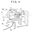
- the first subunit 20A includes a first projection lens 24, a first semiconductor light-emitting device 22, a first reflector 26, and a first shade (shade) 21.
- the first projection lens 24 is arranged on a first optical axis (optical axis) Ax1 that extends in a vehicular longitudinal direction.
- the first semiconductor light-emitting device 22 is arranged on a rear side with respect to a rear side focal point F1 of the first projection lens 24, and is an example of a first light source.
- the first reflector 26 collects and reflects light, irradiated from the first semiconductor light-emitting device 22, toward a front to the first optical axis Ax1.
- the first shade 21 is arranged between the first projection lens 24 and the first semiconductor light-emitting device 22.
- the front edge of the first shade 21 is located near the rear side focal point F1 of the first projection lens 24 to shield part of reflected light R1 coming from the first reflector 26 and part of direct light coming from the first semiconductor light-emitting device 22 to form a cut-off line of the distribution pattern.
- the horizontal surface (upper surface) 21b of the first shade 21 reflects part of reflected light, coming from the first reflector 26, upward.
- the horizontal surface 21b extends toward a rear from the front edge.
- the first semiconductor light-emitting device 22 is a white light-emitting diode that has a light-emitting portion (light-emitting chip) 22a having a size of about 1 square millimeter.
- the first semiconductor light-emitting device 22 is mounted on a support surface 15a of the support member 15 so that the irradiation axis L1 is oriented in a substantially vertically upward direction that is substantially vertical to a direction in which the first subunit 20A irradiates light (leftward direction in FIG. 4 ).
- the light-emitting portion 22a may be arranged at a slight angle depending on the shape of the light-emitting portion or the light distribution irradiated toward the front.
- a plurality of light-emitting portions may be provided in one semiconductor light-emitting device.
- the first reflector 26 is a reflective member inside which a reflective surface 26a is formed.
- the vertical cross-sectional shape of the reflective surface 26a is a substantially elliptical shape, and the horizontal cross-sectional shape thereof is a free-form surface shape based on an ellipse.
- the first reflector 26 is designed and arranged so that the first focal point f1 is located adjacent to the light-emitting portion 22a of the first semiconductor light-emitting device 22 and the second focal point f2 is located adjacent to a ridge line 21c formed by the curved surface 21a and horizontal surface 21b of the first shade 21.
- the first reflector 26 has a pair of first reflective surfaces 27a and 27b outside an effective reflective surface (reflective surface 26a) of the first reflector 26.
- the pair of first reflective surfaces 27a and 27b reflect light R3, irradiated from the first semiconductor light-emitting device 22, toward the second lamp unit 40 arranged on the lower side.
- the distance from the optical axis Ax to the first reflective surface 27a or 27b is larger than the distance from the optical axis Ax to the effective reflective surface.
- the first reflective surfaces 27a and 27b according to the present embodiment are formed of flat surfaces that are respectively provided at both left and right sides at the front end, which is the outside of the effective reflective surface of the first reflector 26.
- the first shade 21 has a block shape and also serves as a support frame of the first projection lens 24.
- the first shade 21 is formed so that the front edge 21c is located near the rear side focal point F1 of the first projection lens 24 to shield part of reflected light R1 coming from the first reflector 26 to thereby form the cut-off line of the distribution pattern and, in addition, the horizontal surface 21b extending rearward from the front edge 21c reflects part of reflected light R1, coming from the first reflector 26, upward.
- the horizontal surface 21b has a light control surface to which reflective surface treatment is applied.
- the front edge 21c of the first shade 21 is formed in a curved shape so that both left and right sides in plan view protrude forward so as to be matched with the curvature of field of the first projection lens 24.
- the curved front edge 21c coincides with the group of focal points of the first projection lens 24. That is, the first shade 21 is formed so that the front edge 21c is formed along the group of focal points of the first projection lens 24 and the shape of the front edge 21c has a cut-off line shape as it is.
- the first shade 21 uses the horizontal surface 21b to reflect part of reflected light R1, coming from the first reflector 26, upward to thereby convert a majority of light emitted upward from the first projection lens 24 into light emitted downward from the first projection lens 24.
- the first shade 21 improves the luminous flux utilization factor of light emitted from the first semiconductor light-emitting device 22.
- the front edge 21c of the first shade 21 used as a border line to selectively cut light to thereby form an oblique cut-off line in the distribution pattern projected toward the front of the vehicle. That is, the front edge 21c constitutes the terminator of the first subunit 20A.
- the horizontal surface 21b of the first shade 21 adjacent to the front of the vehicle has an optical shape for which reflection angle is set in appropriate consideration of the positional relationship between the first projection lens 24 and the first reflector 26.
- transmissive holes 30a and 30b are respectively formed at both left and right sides of the horizontal surface 21b of the first shade 21 in order to allow reflected light R3, reflected on the first reflective surfaces 27a and 27b toward the second lamp unit 40 arranged below the first shade 21, to pass therethrough.
- the first projection lens 24 is a convex aspherical lens that projects light, reflected on the reflective surface 26a of the first reflector 26, toward the front of the vehicle.
- the first projection lens 24 is fixed to the distal end of the first shade 21 adjacent to the front of the vehicle.
- the rear side focal point F1 of the first projection lens 24 substantially coincides with the second focal point f2 of the first reflector 26.
- the first subunit 20A of the first lamp unit 20 constitutes a projector-type light source unit for forming a collection cut.
- the second subunit 20B has a substantially similar configuration to that of the first subunit 20A.
- the second subunit 20B includes a second projection lens 34, a semiconductor light-emitting device 32, a reflector 36, and a second shade 31.
- the second projection lens 34 is arranged on a second optical axis Ax2 extending in the vehicular longitudinal direction and has a smaller rear side focal distance than that of the first projection lens 24.
- the semiconductor light-emitting device 32 is arranged on the rear side with respect to the rear side focal point F2 of the second projection lens 34 and has a similar configuration to that of the first semiconductor light-emitting device 22.
- the reflector 36 collects and reflects light, irradiated from the semiconductor light-emitting device 32, toward the front to the second optical axis Ax2.
- the second shade 31 is arranged between the second projection lens 34 and the semiconductor light-emitting device 32.
- the second shade 31 shields part of reflected light coming from the reflector 36 and part of direct light coming from the semiconductor light-emitting device 32 to form a cut-off line of the distribution pattern.
- the horizontal surface of the second shade 31, extending rearward from the front edge, reflects part of reflected light, coming from the reflector 36, upward. That is, the second subunit 20B of the first lamp unit 20 constitutes a projector-type light source unit for forming a diffusion cut.
- the second lamp unit 40 is a light source unit that forms the distribution pattern of the lower beam together with the above described first lamp unit 20.
- the second lamp unit 40 is arranged below the first lamp unit 20.
- the second lamp unit 40 includes a second semiconductor light-emitting device 42 and a second reflector 46.
- the second semiconductor light-emitting device 42 is an example of a second light source that is fixedly arranged on the support surface 15c of the support member 15.
- the second reflector 46 reflects light, irradiated from the second semiconductor light-emitting device 42, toward the front.
- the second semiconductor light-emitting device 42 is a white diode having a light-emitting portion 42a.
- the second semiconductor light-emitting device 42 is mounted on the support surface 15c of the support member 15 so that the irradiation axis L2 is oriented in a substantially vertically downward direction that is substantially vertical to a direction in which the second lamp unit 40 irradiates light (leftward direction in FIG 3 ).
- the second reflector 46 is a reflective member inside which a reflective surface 46a is formed.
- the reflective surface 46a has a substantially paraboloid of revolution, having a focal point near the light-emitting portion 42a, as a reference surface.
- Light R2 emitted from the light-emitting portion 42a of the second semiconductor light-emitting device 42 is reflected on the reflective surface 46a of the second reflector 46, and is diffused and irradiated to around the front of the vehicle. That is, the second lamp unit 40 according to the present embodiment constitutes a parabolic light source unit for peripheral vision.
- the second lamp unit 40 uses the semiconductor light-emitting device as a light source.
- the vehicular headlamp 10, including the second lamp unit 40 is attached to each of the left and right sides of the vehicle, and the respective second lamp units 40 irradiate diffusion light to left and right toward the front of the vehicle for forming peripheral zone forming patterns.
- the vehicular headlamp 10 including the second lamp unit 40
- the respective second lamp units 40 irradiate diffusion light to left and right toward the front of the vehicle for forming peripheral zone forming patterns.
- the third lamp unit 60 is a light source unit that forms the distribution pattern of the upper beam.
- the third lamp unit 60 includes a reflector 66 and a discharge bulb 70.
- the reflector has a shape of substantially paraboloid of revolution.
- the third optical axis Ax3 of the reflector 66 is tiltable by the aiming mechanism 18.
- the discharge bulb 70 is detachably attached to a bulb fitting hole that is provided at the center of the rear portion of the reflector 66. That is, the third lamp unit 60 according to the present embodiment constitutes a parabolic light source unit that uses a light-emitting bulb as a light source.
- a second reflective surface 50 is provided between the first lamp unit 20 and the second lamp unit 40 that are arranged so that the light-emitting regions are vertically spaced apart from each other.
- the second reflective surface 50 is arranged so that the light-emitting region of the second reflective surface 50 connects the light-emitting region (first region) S1 of the first lamp unit 20 with the light-emitting region (second region) S2 of the second lamp unit 40 and then the light-emitting regions are visually recognized as one light-emitting region S as a whole.
- the light-emitting regions S1 and S2 of the respective first lamp unit 20 and second lamp unit 40 are regions from which the first lamp unit 20 and the second lamp unit 40 respectively emit light outward toward the front of the vehicle.
- the light-emitting region of the second reflective surface 50 is a region on which the second reflective surface 50 reflects radiated light, coming from at least one of the first reflective surfaces 27a and 27b, toward the front of the vehicle.
- the light-emitting region of the second reflective surface 50 is located between the light-emitting region S1 and the light-emitting region S2 as viewed from the front of the vehicle.
- the second reflective surface 50 having a free-form surface is able to reflect radiated light R3, passing through the transmissive hole 30a provided at the right side portion of the horizontal surface 21b of the first shade 21 and coming from the first reflective surface 27a, toward the front.
- the vehicular headlamp 10 according to the present embodiment is a headlamp unit attached to the left front of the vehicle, so the second reflective surface 50 is configured to reflect radiated light R3, coming from the first reflective surface 27a, toward the front; however, when the vehicular headlamp is a head lamp unit attached to the right front of the vehicle, the second reflective surface 50 is configured to reflect radiated light R3, coming from the first reflective surface 27b, toward the front.
- the vehicular headlamp 10 is able to recognize the first lamp unit 20 and the second lamp unit 40, which are a plurality of lamp units, as one light-emitting portion, so recognizability of the lamp as a whole improves.
- the first reflective surfaces 27a and 27b are respectively provided at both left and right sides (both sides in a vehicular widthwise direction) at the front end, which is the outside of the effective reflective surface of the first reflector 26.
- the first shade 21 has the transmissive holes 30a and 30b at both left and right sides of the horizontal surface 21b that is used to reflect part of reflected light, coming from the first reflector 26, upward in order to allow reflected light R3, reflected on the first reflective surfaces 27a and 27b toward the second lamp unit 40 arranged below the first shade 21, to pass therethrough. That is, it is possible to irradiate light R3, reflected on the first reflective surfaces 27a and 27b, to the second reflective surface 50 through these transmissive holes 30a and 30b. Then, the vehicular headlamp 10 has a high flexibility in layout of the second reflective surface 50, so the lamp as a whole may be compact.
- the first reflective surface 27a and the transmissive hole 30a which correspond to the second reflective surface 50 of the vehicular headlamp 10 that is a left headlamp attached to the left front of the vehicle, are provided at the right sides of the first reflector 26 and first shade 21, and the first reflective surface 27b and the transmissive hole 30b, which correspond to the second reflective surface 50 of the vehicular headlamp (not shown) that is a right headlamp attached to the right front of the vehicle, are provided at the left sides of the first reflector 26 and first shade 21.
- the same first subunit 20A in the first lamp unit 20 that includes these first reflector 26 and first shade 21 may be used for the left and right vehicular headlamps.
Landscapes
- Engineering & Computer Science (AREA)
- General Engineering & Computer Science (AREA)
- Physics & Mathematics (AREA)
- Microelectronics & Electronic Packaging (AREA)
- Optics & Photonics (AREA)
- Mechanical Engineering (AREA)
- Non-Portable Lighting Devices Or Systems Thereof (AREA)
Applications Claiming Priority (1)
| Application Number | Priority Date | Filing Date | Title |
|---|---|---|---|
| JP2009049710A JP5344957B2 (ja) | 2009-03-03 | 2009-03-03 | 車両用前照灯 |
Publications (2)
| Publication Number | Publication Date |
|---|---|
| EP2226555A2 true EP2226555A2 (de) | 2010-09-08 |
| EP2226555A3 EP2226555A3 (de) | 2012-04-25 |
Family
ID=42226644
Family Applications (1)
| Application Number | Title | Priority Date | Filing Date |
|---|---|---|---|
| EP10154315A Withdrawn EP2226555A3 (de) | 2009-03-03 | 2010-02-23 | Fahrzeugscheinwerfer |
Country Status (2)
| Country | Link |
|---|---|
| EP (1) | EP2226555A3 (de) |
| JP (1) | JP5344957B2 (de) |
Cited By (2)
| Publication number | Priority date | Publication date | Assignee | Title |
|---|---|---|---|---|
| CN104344311A (zh) * | 2013-08-06 | 2015-02-11 | 株式会社小糸制作所 | 车辆用灯具 |
| FR3021729A1 (fr) * | 2014-06-03 | 2015-12-04 | Valeo Vision | Module lumineux pour vehicule |
Families Citing this family (2)
| Publication number | Priority date | Publication date | Assignee | Title |
|---|---|---|---|---|
| JP5729141B2 (ja) * | 2011-05-31 | 2015-06-03 | 市光工業株式会社 | 車両用前照灯 |
| JP6048773B2 (ja) * | 2015-08-07 | 2016-12-21 | スタンレー電気株式会社 | 車両用灯具ユニット |
Citations (1)
| Publication number | Priority date | Publication date | Assignee | Title |
|---|---|---|---|---|
| JP2007305575A (ja) | 2006-04-11 | 2007-11-22 | Koito Mfg Co Ltd | 車両用灯具 |
Family Cites Families (6)
| Publication number | Priority date | Publication date | Assignee | Title |
|---|---|---|---|---|
| DE19526023A1 (de) * | 1995-07-17 | 1997-01-23 | Daimler Benz Ag | Scheinwerfer |
| JP3779173B2 (ja) * | 2001-04-24 | 2006-05-24 | 株式会社小糸製作所 | 車両用前照灯 |
| JP4536479B2 (ja) * | 2003-12-02 | 2010-09-01 | 株式会社小糸製作所 | 車両用前照灯 |
| JP4600994B2 (ja) * | 2005-08-31 | 2010-12-22 | 本田技研工業株式会社 | 車両用照明装置 |
| FR2897672B1 (fr) * | 2006-02-22 | 2008-07-04 | Peugeot Citroen Automobiles Sa | Bloc optique a fonctions d'eclairement couplees |
| DE102007016294B4 (de) * | 2006-04-11 | 2009-04-02 | Koito Manufacturing Co., Ltd. | Fahrzeugleuchte |
-
2009
- 2009-03-03 JP JP2009049710A patent/JP5344957B2/ja not_active Expired - Fee Related
-
2010
- 2010-02-23 EP EP10154315A patent/EP2226555A3/de not_active Withdrawn
Patent Citations (1)
| Publication number | Priority date | Publication date | Assignee | Title |
|---|---|---|---|---|
| JP2007305575A (ja) | 2006-04-11 | 2007-11-22 | Koito Mfg Co Ltd | 車両用灯具 |
Cited By (5)
| Publication number | Priority date | Publication date | Assignee | Title |
|---|---|---|---|---|
| CN104344311A (zh) * | 2013-08-06 | 2015-02-11 | 株式会社小糸制作所 | 车辆用灯具 |
| CN104344311B (zh) * | 2013-08-06 | 2017-09-19 | 株式会社小糸制作所 | 车辆用灯具 |
| US10024508B2 (en) | 2013-08-06 | 2018-07-17 | Koito Manufacturing Co., Ltd. | Vehicle lamp |
| FR3021729A1 (fr) * | 2014-06-03 | 2015-12-04 | Valeo Vision | Module lumineux pour vehicule |
| EP2952804A1 (de) * | 2014-06-03 | 2015-12-09 | Valeo Vision | Leuchtmodul für fahrzeug und befestigungsverfahren |
Also Published As
| Publication number | Publication date |
|---|---|
| JP5344957B2 (ja) | 2013-11-20 |
| JP2010205558A (ja) | 2010-09-16 |
| EP2226555A3 (de) | 2012-04-25 |
Similar Documents
| Publication | Publication Date | Title |
|---|---|---|
| EP2216590B1 (de) | Fahrzeuglampe | |
| JP6246007B2 (ja) | 車両用灯具 | |
| JP4391870B2 (ja) | 車両用照明灯具 | |
| EP2487407B1 (de) | Fahrzeugbeleuchtungsvorrichtung | |
| CN111196205B (zh) | 车灯装置及高速照明车灯模块 | |
| US7712936B2 (en) | Vehicle lighting unit | |
| KR100858953B1 (ko) | 차량용 등기구 | |
| EP2407710B1 (de) | Fahrzeugleuchte | |
| JP4781951B2 (ja) | 車両用灯具ユニット及び車両用灯具 | |
| EP2784375B1 (de) | Fahrzeugscheinwerfer | |
| US7866862B2 (en) | Vehicular lamp | |
| EP2028411B1 (de) | Kurvenfahrtscheinwerfer für Fahrzeug | |
| JP5574411B2 (ja) | 車両用灯具ユニット | |
| JP2004095479A (ja) | 車両用前照灯 | |
| JP2009184410A (ja) | 車両用照明灯具 | |
| JP2010212089A (ja) | 車両用灯具 | |
| JP2005317226A (ja) | 車両用照明灯具 | |
| EP2075500A2 (de) | Fahrzeugscheinwerfer | |
| EP2226555A2 (de) | Fahrzeugscheinwerfer | |
| CN111867886A (zh) | 车辆用灯具及车辆用灯具系统 | |
| JP2014229441A (ja) | 車両用灯具 | |
| JP2008243476A (ja) | 車両用灯具 | |
| JP2015146270A (ja) | 車両用灯具 | |
| JP4647650B2 (ja) | 光源ユニットおよび車両用灯具 |
Legal Events
| Date | Code | Title | Description |
|---|---|---|---|
| PUAI | Public reference made under article 153(3) epc to a published international application that has entered the european phase |
Free format text: ORIGINAL CODE: 0009012 |
|
| 17P | Request for examination filed |
Effective date: 20100223 |
|
| AK | Designated contracting states |
Kind code of ref document: A2 Designated state(s): AT BE BG CH CY CZ DE DK EE ES FI FR GB GR HR HU IE IS IT LI LT LU LV MC MK MT NL NO PL PT RO SE SI SK SM TR |
|
| PUAL | Search report despatched |
Free format text: ORIGINAL CODE: 0009013 |
|
| AK | Designated contracting states |
Kind code of ref document: A3 Designated state(s): AT BE BG CH CY CZ DE DK EE ES FI FR GB GR HR HU IE IS IT LI LT LU LV MC MK MT NL NO PL PT RO SE SI SK SM TR |
|
| RIC1 | Information provided on ipc code assigned before grant |
Ipc: B60Q 1/00 20060101ALI20120321BHEP Ipc: F21V 7/00 20060101AFI20120321BHEP Ipc: F21W 101/10 20060101ALN20120321BHEP |
|
| STAA | Information on the status of an ep patent application or granted ep patent |
Free format text: STATUS: THE APPLICATION HAS BEEN WITHDRAWN |
|
| 18W | Application withdrawn |
Effective date: 20160129 |