EP2223391B1 - Elektrisches kontaktelement - Google Patents
Elektrisches kontaktelement Download PDFInfo
- Publication number
- EP2223391B1 EP2223391B1 EP08864948.8A EP08864948A EP2223391B1 EP 2223391 B1 EP2223391 B1 EP 2223391B1 EP 08864948 A EP08864948 A EP 08864948A EP 2223391 B1 EP2223391 B1 EP 2223391B1
- Authority
- EP
- European Patent Office
- Prior art keywords
- contact
- spring arms
- contact element
- element according
- preceding patent
- Prior art date
- Legal status (The legal status is an assumption and is not a legal conclusion. Google has not performed a legal analysis and makes no representation as to the accuracy of the status listed.)
- Active
Links
Images





Classifications
-
- H—ELECTRICITY
- H01—ELECTRIC ELEMENTS
- H01R—ELECTRICALLY-CONDUCTIVE CONNECTIONS; STRUCTURAL ASSOCIATIONS OF A PLURALITY OF MUTUALLY-INSULATED ELECTRICAL CONNECTING ELEMENTS; COUPLING DEVICES; CURRENT COLLECTORS
- H01R13/00—Details of coupling devices of the kinds covered by groups H01R12/70 or H01R24/00 - H01R33/00
- H01R13/02—Contact members
- H01R13/10—Sockets for co-operation with pins or blades
- H01R13/11—Resilient sockets
- H01R13/111—Resilient sockets co-operating with pins having a circular transverse section
-
- H—ELECTRICITY
- H01—ELECTRIC ELEMENTS
- H01R—ELECTRICALLY-CONDUCTIVE CONNECTIONS; STRUCTURAL ASSOCIATIONS OF A PLURALITY OF MUTUALLY-INSULATED ELECTRICAL CONNECTING ELEMENTS; COUPLING DEVICES; CURRENT COLLECTORS
- H01R2103/00—Two poles
-
- H—ELECTRICITY
- H01—ELECTRIC ELEMENTS
- H01R—ELECTRICALLY-CONDUCTIVE CONNECTIONS; STRUCTURAL ASSOCIATIONS OF A PLURALITY OF MUTUALLY-INSULATED ELECTRICAL CONNECTING ELEMENTS; COUPLING DEVICES; CURRENT COLLECTORS
- H01R24/00—Two-part coupling devices, or either of their cooperating parts, characterised by their overall structure
- H01R24/76—Two-part coupling devices, or either of their cooperating parts, characterised by their overall structure with sockets, clips or analogous contacts and secured to apparatus or structure, e.g. to a wall
- H01R24/78—Two-part coupling devices, or either of their cooperating parts, characterised by their overall structure with sockets, clips or analogous contacts and secured to apparatus or structure, e.g. to a wall with additional earth or shield contacts
-
- H—ELECTRICITY
- H01—ELECTRIC ELEMENTS
- H01R—ELECTRICALLY-CONDUCTIVE CONNECTIONS; STRUCTURAL ASSOCIATIONS OF A PLURALITY OF MUTUALLY-INSULATED ELECTRICAL CONNECTING ELEMENTS; COUPLING DEVICES; CURRENT COLLECTORS
- H01R27/00—Coupling parts adapted for co-operation with two or more dissimilar counterparts
- H01R27/02—Coupling parts adapted for co-operation with two or more dissimilar counterparts for simultaneous co-operation with two or more dissimilar counterparts
Definitions
- the invention relates to a contact element according to the preamble of claim 1.
- Sockets with socket-shaped contact elements for receiving pins of appliance connectors are known in electrical home installations and are used in the initial equipment as well as in the retrofit area. Often it is important to be able to functionally upgrade such electrical installation devices. For this reason, it has proved to be advantageous to provide corresponding assemblies that can be mounted as needed in addition to the existing installation device.
- From the EP 1 560 301 A1 is a contact element with two contact points and a terminal known.
- the contact element is formed on the one hand by a first contact point and on the other hand by a second contact point with a terminal, wherein a central wall forms the connection between the two areas. Due to the location of the two contact points and opposite directions of insertion results in a functional Independence, but at the same time arise two separate contact areas for the contact element.
- From the DE 27 52 592 A1 is a contact element with two contact points and a terminal known.
- the terminal is directly connected to a first contact point, while the second contact point is connected via an intermediate element with the first contact point.
- a direct connection of the second contact point to the terminal is not available. Due to the arrangement and the position of the two contact points arise two separate contact areas (double socket), which act mechanically on each other through the intermediate element.
- the object of the present invention is therefore to eliminate the above-mentioned disadvantages and to provide a contact element which enables a secure and easy to assemble contact of at least two elements.
- the invention according to claim 1 has the advantage that a releasable contact for a device connector and a further assembly is provided, wherein mechanically and functionally independent contact points are formed in a one-piece contact region of a contact element.
- the contact element consists of a connection region for the connection of supply lines and opposite from the one-piece contact region for at least two elements.
- each spring arm pair forms a socket for receiving a contact pin.
- the Federarmcrue from the base parallel to each other and are separated by a slot.
- the upper spring arms are bent backwards inwardly and form between them a socket for a contact pin.
- the height of the spring arms rises on both sides up to the bending point and drops off to one side on the bushing.
- the lower spring arms protrude in the longitudinal extension over the upper spring arms and are stepped in the longitudinal direction inwardly bent and occur immediately in front of the front-side terminating bush in abutment with each other.
- the height of the spring arms is constant.
- Federarmcrue allows different clamping forces on the respective sockets. Since decreasing clamping forces can be achieved with increasing length of the spring arm pairs, the circumferentially larger contact pins in the shorter spring arms are conveniently contacted, while the thin contact pins, with less contact force, are contacted in the longer spring arms.
- Conical designs of the socket facilitate the insertion.
- the upper portion of the sleeve of the upper spring arm pair is not tied to the spring arms, so that the insertion of a contact pin is further facilitated.
- the contact pin widened the socket initially only on top and then slips along a resulting inclination with further expansion in the socket.
- the twisting effect also acts, so that an "ejection" of the contact pin or the plug takes place at the end.
- the sleeve is deformed a little elastically when applying the pull-out force even before reaching the limit for the sliding friction. As a result, the power conditions change within the socket and the plug can be solved easily.
- the contact element according to the invention allows a universally usable installation device that can be upgraded if necessary with a suitable modular assembly, with a simple assembly and disassembly is maintained.
- a simple assembly and disassembly is maintained.
- by the mechanical assembly of the assembly simultaneously their electrical contact. Separate connection work, such. As soldering, deleted
- the contact element is suitable both for plugged from the front and / or from the back pins.
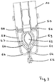
- the structure of the contact element according to the invention is based on the FIGS. 1 and 2 described in more detail.
- the contact element 8 is z. B. of multi-machined, preferably bent, copper sheet and has a box-shaped basic structure. From a centrally located base 50 opposite a terminal 10 for the connection of supply lines and a one-piece contact area 51 with separated contact points 52 and 53 for different pins 32, 33 and 54, preferably from a device connector, not shown, and from a module 2, from.
- In the contact region 51 extend from the base 50 opposite slightly inwardly inclined spring legs 55 and 56, which merge integrally into a separated by a slot 57 upper Federarmcru 58, 59 and a lower Federarmcru 60, 61.
- the dimensioning of the upper spring arms 58 and 59 and lower spring arms 60 and 61 is designed for the mechanical loads of different thickness contact pins 32, 33 and 54.
- the upper spring arms 58 and 59 are each initially in continuation of the spring legs 55 and 56 continue slightly inclined and are then bent inwards by almost 180 degrees and form a socket 62.
- the bush 62 has an outwardly bent collar 63 to facilitate the insertion of a contact pin 54.
- the height H1 of the spring arms 58 and 59 increases starting at the top of the spring legs 55 and 56 evenly to the bending point 64 to a maximum and falls to the socket 62 back to the original height.
- the contact point 52 is stable and mechanical stresses are mainly in the material strong bending point 64 intercepted and not transferred to the base 50.
- the contact point 52 is preferably designed for the clamping reception of contact pins 54 in the range of 4-5 mm, z. B. a device plug.
- the lower pair of spring arms 60, 61 projects longitudinally beyond the upper spring arm pair 58, 59.
- the spring arms 60 and 61 are each stepped inwardly bent and occur in front of a front-side final sleeve 65 in abutment with each other.
- the height H2 of the spring arms 60 and 61 is constant and less than the height H1 of the upper spring arms 58 and 59.
- the sleeve 65 is preferably designed for clamping receiving pins 32, 33 in the range of 1 mm, with the slight expansion of the sleeve 65th in connection with the length and the height H2 of the spring arms 60, 61 results in a self-supporting contact point 53, which transmits no forces to the base 50.
- an electrical installation device 1 shown in the form of a socket, which is equipped with contact elements 8, 9 according to the invention.
- the installation device 1 is on the one hand equipped with an optional module 2 for overvoltage protection and on the other hand provided with a device plug.
- the installation device 1 has a device base 3, which is formed in principle circular and block-like and consists of insulating materials.
- the device base 3 surrounds on the outside an annular support frame 4, which is preferably mounted latching.
- the support frame 4 is made of either metallic or non-metallic materials, preferably plastic.
- Radial opposite to the device base 3 and on the support frame 4 not shown claw-like fastening means are provided which allow the attachment of the installation device 1 in a stationary installation housing, not shown.
- the device base 3 and the support frame 4 an assembly unit. Front side, a function-specific front element 5 is fixed, which may be one or more parts depending on the application. ( FIG. 3 )
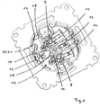
- the metallic contact elements 8 and 9 are arranged under so-called release elements 6 and 7, in the front plug pins of a device plug, not shown, are plugged in and the rear side via terminals 10 and 11 are connected to supply lines. Furthermore, in the device base 3, a multiply bent grounding strap 12 is arranged, which serves for the front-side contacting of a ground contact of the device connector and the back-side connection of a ground conductor to a terminal 13.
- the two contact elements 8 and 9 are mounted centrally in the device base 3 in correspondingly shaped chambers 14 and 15.
- the connection terminals 10, 11 are arranged uniformly in a connection region 16 of the device base 3.
- a cylindrically extending receiving space 19 is formed within the one-piece device base 3 by a radial outer wall 17 and a rectilinear inner wall 18, which has a circular segment-shaped base surface 20 which is formed by a rear base plate 21.
- FIG. 3 closes in the unpopulated state, a removable cover 22 this receiving space 19, wherein the cover 22 is arranged flush with the release elements 6 and 7.
- On the bottom plate 21 within the receiving space 19 are locking lugs, which serve to fix the module 2.
- the chambers 14 and 15 of the contact elements 8 and 9 extend on the bottom side.
- the grounding bar 12 is arranged between the two contact elements 8 and 9 and extends initially at the bottom and then bent vertically along the outer wall 17 in the receiving space 19.
- a form-fitting module 2 can be used.
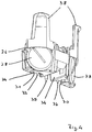
- the module 2 consists of insulating material and has a cylindrical space extension, starting with a circular segment-shaped base 24 from which a straight wall and a curved wall 26 extend, which are closed by a cover 27. On the walls of various recesses, cutouts and approaches are formed.
- various components are arranged, for example, varistors 28, gas discharge, a circuit board, resistors, light elements and contact elements. This makes it possible, for example, to implement an overvoltage protection unit.
- projections 38 are formed, which facilitate the insertion and, if necessary, the removal of the module 2. Furthermore, there is a pin-shaped projection 39 on the upper side of the module 2 at the edge, in order to be able to selectively direct light signals from the module 2 to display elements in the front element 5. For this purpose, at least the approach 39 of a photoconductive material such. Eg PC or PMMA, molded. A light element in the form of an LED 40 is arranged in a recess 41.
- the installation or function of the installation device 1 will be briefly described below.
- a basic version of an installation device 1 consists of a device base 3 equipped with the contact elements 8 and 9 and the earth strap 12 and the support frame 4 attached thereto.
- the receiving space 19 is closed by a cover 22 and there is no module 2 therein.
- Such a unit is usually connected in a flush-mounted box by means of the connection terminals 10, 11, 13 to supply lines and fixed by the claw-like fastening means. Finally, the front element 5 is attached.
- the electrical installation device 1 is retrofitted, for example, to integrate an overvoltage protection.
- the front element 5 and then the cover 22 of the device base 3 is removed. Due to the positive connection, a module 2 can be pushed linearly without tilting up to the stop in the circular segment-shaped receiving space 19. It is automatically mechanically latched as well as electrically contacted, without an expansion of the installation unit 1 or additional connection work is necessary.
- the module 2 is arranged flush with the release elements 6 and 7 after assembly. Only the extensions 38 protrude, but close off with the support frame 4.
- the locking lugs projecting from the bottom plate 21 of the receiving space 19 engage in the recesses of the module 2.
- the contact pins 32 and 33 slide through the positive cooperation of the chambers 14 and 15 and the free spaces 30 and 31 in the contact elements 8 and 9.
- the contact pin 35 slides into a slot 45 in the grounding strap 12, wherein the grounding strap 12 is enclosed by the groove 34.
- FIGS. 7 and 8th is the contacting of each of a contact pin 32, 54 of the module 2 and the device plug, not shown, shown on an enlarged scale. Both the module 2 and the device plug are inserted front and parallel to each other.
- the contact pin 32 of the module 2 is inserted into the contact point 53 of the contact element 8 in the socket 65 of the lower spring arm pair 60, 61, wherein the positive connection between the module 2 and the receiving space 19 provides sufficient centering, so that the contact pin 32 inserted without centering can be.
- the contact pin 32 widens the socket 65 and is pushed to its end position. In the end position, the spring arms 60 and 61 are slightly widened and clampingly surround the contact pin 32. The spring arms 60 and 61 touch the chamber 14 and increase the contact pressure.
- the contact pin 54 of the device plug is inserted into the contact point 52 of the contact element 8 in the socket 62 of the upper Federarmpases 58, 59, wherein initially a centering in the collar 63 of the sleeve 62 takes place. Subsequently, the contact pin 54 expands the sleeve 62 on top and then slides along the resulting inclination of the spring arms 58 and 59 with further expansion in the socket 62 to its final position. In the end position, the spring arms 58 and 59 are slightly widened and clampingly surround the contact pin 54, wherein a sufficiently high contact pressure due to the shortness of the spring arms 58 and 59, the contact pin 54 securely contacted. The contacting of the contact pin 32 of the module 2 in the contact element 8 remains in the contacting of the contact pin 54 of the device plug in the same contact element 8 Reason for the separation of the contact points 52 and 53 without mechanical interactions.
- the twisting effect described also acts, so that an "ejection" of the device plug takes place to the end.
- the sleeve 62 is deformed a little elastically when applying the pull-out force even before reaching the limit for the sliding friction. As a result, the power conditions change within the socket 62 and the device connector is easier to solve.
Landscapes
- Details Of Connecting Devices For Male And Female Coupling (AREA)
- Connector Housings Or Holding Contact Members (AREA)
- Connecting Device With Holders (AREA)
Description
- Die Erfindung betrifft ein Kontaktelement nach dem Oberbegriff des Patentanspruches 1.
- Steckdosen mit buchsenförmigen Kontaktelementen zur Aufnahme von Kontaktstiften von Gerätesteckern sind bei elektrischen Hausinstallationen bekannt und werden bei der Erstausstattung als auch im Nachrüstbereich eingesetzt. Häufig ist es wichtig, derartige elektrische Installationsgeräte funktional aufrüsten zu können. Aus diesem Grund hat es sich als vorteilhaft erwiesen, entsprechende Baugruppen zu schaffen, die bei Bedarf an das vorhandene Installationsgerät ergänzend montiert werden können.
- Aus dem Stand der Technik, beispielsweise aus der
EP 0 281 969 B1 , ist ein elektrisches Installationsgerät bekannt, bei dem frontseitig ein Gerätestecker lösbar in entsprechende Kontaktelemente gesteckt wird, während rückseitig eine optionale Baugruppe angeordnet werden kann. Nachteilig ist dabei, dass die elektrische Kontaktierung des rückseitigen Moduls durch eine unlösbare Verbindung mit in dem Installationsgerät vorhandenen Kontaktelementen erfolgt. Derartige Anordnungen und Verfahren bedeuten einen erhöhten Montageaufwand und sind nicht besonders praktikabel. - Aus der
EP 1 560 301 A1 ist ein Kontaktelement mit zwei Kontaktstellen und einer Anschlussklemme bekannt. Das Kontaktelement wird einerseits durch eine erste Kontaktstelle und andererseits durch eine zweite Kontaktstelle mit einer Anschlussklemme gebildet, wobei eine mittige Wand die Verbindung beider Bereiche bildet. Aufgrund der Lage der beiden Kontaktstellen und gegensätzlicher Steckrichtungen ergibt sich eine funktionale Unabhängigkeit, aber gleichzeitig entstehen jeweils zwei separate Kontaktbereiche für das Kontaktelement. - Aus der
DE 27 52 592 A1 ist ein Kontaktelement mit zwei Kontaktstellen und einer Anschlussklemme bekannt. Die Anschlussklemme ist direkt mit einer ersten Kontaktstelle verbunden, während die zweite Kontaktstelle über ein Zwischenelement mit der ersten Kontaktstelle verbunden ist. Eine direkte Anbindung der zweiten Kontaktstelle an die Anschlussklemme ist nicht vorhanden. Aufgrund der Anordnung und der Lage der beiden Kontaktstellen entstehen zwei separate Kontaktbereiche (Doppelsteckdose), die durch das Zwischenelement mechanisch aufeinander einwirken. - Die Aufgabe der vorliegenden Erfindung besteht deshalb darin, die vorstehend genannten Nachteile zu beseitigen und ein Kontaktelement zu schaffen, das eine sichere und montagefreundliche Kontaktierung von mindestens zwei Elementen ermöglicht.
- Gelöst wird diese Aufgabe durch die im Patentanspruch 1 angegebenen Merkmale. Vorteilhafte Ausgestaltungen ergeben sich aus den- Unteransprüchen.
- Die Erfindung gemäß dem Patentanspruch 1 weist den Vorteil auf, dass eine lösbare Kontaktierung für einen Gerätestecker und eine weitere Baugruppe geschaffen wird, wobei mechanisch und funktional unabhängige Kontaktstellen in einem einteiligen Kontaktbereich eines Kontaktelementes ausgebildet sind. Das Kontaktelement besteht aus einem Anschlussbereich für den Anschluss von Versorgungsleitungen und gegenüberliegend aus dem einteiligen Kontaktbereich für mindestens zwei Elementen.
- Die mechanischen Vorgänge bei der Steckung der jeweiligen Kontaktstifte werden nicht von einer Kontaktstelle auf die andere Kontaktstelle übertragen, so dass die Klemmkräfte keinen Wechselwirkungen unterliegen und eine ununterbrochene und damit sichere Kontaktierung gewährleistet ist. Die Steckkräfte und -bewegungen der Buchsen werden unabhängig voneinander von den Federarmen aufgefangen, so dass durch die Steckung unterschiedlicher Baugruppen in ein und das selbe Kontaktelement die bei lösbaren Kontaktierungen wesentlichen Verbindungseigenschaften wie Klemm- bzw. Kontaktkräfte nicht beeinflusst werden. Ein derart vorteilhafter Effekt wird durch separat von einer gemeinsamen Basis an dem Kontaktelement ausgeführte Federarmpaare ermöglicht, wobei jedes Federarmpaar eine Buchse zur Aufnahme eines Kontaktstiftes ausbildet. Dabei verlaufen die Federarmpaare von der Basis parallel zueinander und sind durch einen Schlitz voneinander getrennt.
- Durch unterschiedliche Ausbildung der Federarmpaare und unterschiedliche Positionierung der jeweiligen Buchsen werden Steckpositionen für zwei parallel steckbare Elemente, beispielsweise einen Gerätestecker und ein Modul, geschaffen. Somit ist die übliche und praktische Steckung von der Frontseite und/oder der Rückseite weiterhin möglich.
- Von der Basis erstrecken sich gegenüberliegende Federschenkel, die sich in die beiden Federarmpaare aufteilen. Die oberen Federarme sind rückwärts einwärts gebogen und bilden zwischen sich eine Buchse für einen Kontaktstift aus. Die Höhe der Federarme steigt beidseits bis zur Biegestelle an und fällt zur Buchse hin einseitig wieder ab. Die Buchse wird hierdurch in sich stabil und mechanische Belastungen werden hauptsächlich in der Material starken Biegung abgefangen und nicht auf die Basis übertragen werden. Die unteren Federarme stehen in Längserstreckung über die oberen Federarme vor und sind in Längserstreckung abgestuft einwärts gebogen und treten unmittelbar vor der vorderseitig abschließenden Buchse in Anlage zueinander. Die Höhe der Federarme ist gleichbleibend.
- Die unterschiedliche Ausbildung der Federarmpaare ermöglicht unterschiedliche Klemmkräfte an den jeweiligen Buchsen. Da mit zunehmender Länge der Federarmpaare abnehmende Klemmkräfte realisierbar sind, werden praktischerweise die umfangsmäßig größeren Kontaktstifte in den kürzeren Federarmen kontaktiert, während die dünnen Kontaktstifte, mit geringerer Kontaktkraft, in den längeren Federarmen kontaktiert sind.
- Konische Ausbildungen der Buchse erleichtern das Einstecken. Darüber hinaus ist der obere Bereich der Buchse des oberen Federarmpaares nicht an die Federarme angebunden wird, so dass das Einstecken eines Kontaktstiftes weiter erleichtert wird. Der Kontaktstift weitet die Buchse zunächst nur oben auf und rutscht dann entlang einer sich ergebenden Neigung unter weiterer Aufweitung in die Buchse. Beim Ausziehen des Kontaktstiftes wirkt der Verdreheffekt ebenfalls, so dass ein "Auswerfen" des Kontaktstiftes bzw. des Steckers zum Ende erfolgt. Außerdem wird beim Aufbringen der Auszugskraft noch vor Erreichen der Grenze für die Gleitreibung die Buchse ein wenig elastisch verformt. Dadurch verändern sich die Kraftverhältnisse innerhalb der Buchse und der Stecker lässt sich leichter lösen.
- Eine zusätzliche Versteifung und ein Schutz gegen übermäßiges Aufweiten der Buchse und der Federarme erfolgt durch eine formschlüssige Positionierung des Kontaktelementes in entsprechenden Kammern des Gerätesockels.
- Das erfindungsgemäße Kontaktelement ermöglicht ein universell verwendbares Installationsgerät, das im Bedarfsfall mit einer geeigneten modularen Baugruppe aufgerüstet werden kann, wobei eine einfache Montage und Demontage erhalten bleibt. Vorteilhafterweise erfolgt durch die mechanische Montage der Baugruppe gleichzeitig deren elektrische Kontaktierung. Separate Anschlussarbeiten, wie z. B. Löten, entfällt Das Kontaktelement eignet sich sowohl für von der Frontseite und/oder von der Rückseite gesteckte Kontaktstifte.
- Weitere Einzelheiten, Merkmale und Vorteile der Erfindung ergeben sich aus nachfolgender Beschreibung eines bevorzugten Ausführungsbeispieles anhand der Zeichnungen.
- Es zeigen:
- Figur 1
- eine perspektivische Ansicht eines Kontaktelementes.
- Figur 2
- eine Draufsicht des Kontaktelementes.
- Figur 3
- eine perspektivische Ansicht eines Installationsgerätes mit Frontelement und mit Abdeckung.
- Figur 4
- eine perspektivische Ansicht eines Moduls.
- Figur 5
- eine perspektivische Ansicht des Installationsgerätes und des Moduls vor der Montage.
- Figur 6
- eine perspektivische Ansicht des Installationsgerätes aus
Figur 5 ohne Löseelement. - Figur 7
- eine vergrößerte Ansicht aus
Figur 6 . - Figur 8
- eine vergrößerte Ansicht gemäß
Figur 7 mit eingeführten Kontaktstiften. - Gleiche oder gleichwirkende Bauteile sind in der nachfolgenden Beschreibung mit gleichen Bezugszeichen versehen.
- Der Aufbau des erfindungsgemäßen Kontaktelementes wird anhand der
Figuren 1 und2 näher beschrieben. - Das Kontaktelement 8 besteht z. B. aus mehrfach bearbeitetem, vorzugsweise gebogenem, Kupferblech und weist eine kastenförmige Grundstruktur auf. Von einer mittig angeordneten Basis 50 gehen gegenüberliegend eine Anschlussklemme 10 für den Anschluss von Versorgungsleitungen und ein einteiliger Kontaktbereich 51 mit separierten Kontaktstellen 52 und 53 für unterschiedliche Kontaktstifte 32, 33 und 54, vorzugsweise von einem nicht dargestellten Gerätestecker und von einem Modul 2, ab. Im Kontaktbereich 51 erstrecken sich von der Basis 50 gegenüberliegende leicht einwärts geneigte Federschenkel 55 und 56, die einstückig in ein durch einen Schlitz 57 getrenntes oberes Federarmpaar 58, 59 und ein unteres Federarmpaar 60, 61 übergehen. Die Dimensionierung der oberen Federarme 58 und 59 und unteren Federarme 60 und 61 ist auf die mechanischen Belastungen der unterschiedlich dicken Kontaktstifte 32, 33 und 54 ausgelegt.
- Die oberen Federarme 58 und 59 verlaufen jeweils zunächst in Fortsetzung der Federschenkel 55 und 56 weiterhin leicht geneigt und sind anschließend um nahezu 180 Grad einwärts gebogen und bilden eine Buchse 62 aus. Am oberen Ende weist die Buchse 62 einen nach außen gebogenen Kragen 63 auf, um das Einstecken eines Kontaktstiftes 54 zu erleichtern. Die Höhe H1 der Federarme 58 und 59 steigt beginnend an den Federschenkeln 55 und 56 oberseitig gleichmäßig bis zur Biegestelle 64 auf ein Maximum an und fällt bis zur Buchse 62 wieder auf die Ursprungshöhe ab. Hierdurch wird die Kontaktstelle 52 in sich stabil und mechanische Belastungen werden hauptsächlich in der Material starken Biegestelle 64 abgefangen und nicht auf die Basis 50 übertragen. Die Kontaktstelle 52 ist vorzugsweise zur klemmenden Aufnahme von Kontaktstiften 54 im Bereich von 4-5 mm ausgelegt, z. B. eines Gerätesteckers.
- Das untere Federarmpaar 60, 61 steht in Längserstreckung über das obere Federarmpaar 58, 59 vor. Die Federarme 60 und 61 sind jeweils abgestuft einwärts gebogen und treten unmittelbar vor einer vorderseitig abschließenden Buchse 65 in Anlage zueinander. Die Höhe H2 der Federarme 60 und 61 ist gleichbleibend und geringer als die Höhe H1 der oberen Federarme 58 und 59. Die Buchse 65 ist vorzugsweise zur klemmenden Aufnahme von Kontaktstiften 32, 33 im Bereich von 1 mm ausgelegt, wobei die geringe Aufweitung der Buchse 65 im Zusammenhang mit der Länge und der Höhe H2 der Federarme 60, 61 eine selbsttragende Kontaktstelle 53 ergibt, die keine Kräfte auf die Basis 50 überträgt.
- Nachfolgend ist beispielhaft ein elektrisches Installationsgerät 1 in Form einer Steckdose dargestellt, die mit erfindungsgemäßen Kontaktelementen 8, 9 bestückt ist. Das Installationsgerät 1 wird einerseits mit einem optionalen Modul 2 für den Überspannungsschutz ausgestattet und andererseits mit einem Gerätestecker versehen.
- Das Installationsgerät 1 weist einen Gerätesockel 3 auf, der prinzipiell kreisförmig und blockartig ausgebildet ist und aus isolierenden Materialien besteht. Den Gerätesockel 3 umgibt außenseitig ein ringförmiger Tragrahmen 4, der vorzugsweise rastend befestigt ist. Der Tragrahmen 4 ist entweder aus metallischen oder aus nichtmetallischen Werkstoffen, vorzugsweise Kunststoff, gefertigt. Radial gegenüberliegend sind an dem Gerätesockel 3 bzw. an dem Tragrahmen 4 nicht näher dargestellte krallenartige Befestigungsmittel vorgesehen, die die Befestigung des Installationsgerätes 1 in einem nicht dargestellten ortsfesten Installationsgehäuse ermöglichen. Vorzugsweise bilden der Gerätesockel 3 und der Tragrahmen 4 eine Montageeinheit. Frontseitig ist ein funktionsspezifisches Frontelement 5 befestigt, das je nach Anwendung ein- oder mehrteilig sein kann. (
Figur 3 ) - In dem Gerätesockel 3 sind unter sogenannten Löseelementen 6 und 7 die metallischen Kontaktelemente 8 und 9 angeordnet, in die frontseitig Steckerstifte eines nicht dargestellten Gerätesteckers gesteckt werden und die rückseitig über Anschlussklemmen 10 und 11 mit Versorgungsleitungen verbunden werden. Des weiteren ist in dem Gerätesockel 3 ein mehrfach gebogener Erdungsbügel 12 angeordnet, der zur frontseitigen Kontaktierung eines Erdungskontaktes des Gerätesteckers und zum rückseitigen Anschluss eines Erdleiters an eine Anschlussklemme 13 dient.
- Die beiden Kontaktelemente 8 und 9 sind mittig des Gerätesockels 3 in entsprechend geformten Kammern 14 und 15 befestigt. Die Anschlussklemmen 10, 11 sind einheitlich in einem Anschlussbereich 16 des Gerätesockels 3 angeordnet. Auf der radial gegenüberliegenden Seite ist innerhalb des einstückigen Gerätesockels 3 durch eine radiale Außenwand 17 und eine geradlinige Innenwand 18 ein sich zylindrisch erstreckender Aufnahmeraum 19 gebildet, der eine kreissegmentförmige Grundfläche 20 aufweist, die durch eine rückseitige Bodenplatte 21 gebildet wird. (
Figuren 5 und6 ) - Gemäß
Figur 3 verschließt im unbestückten Zustand eine entfernbare Abdeckung 22 diesen Aufnahmeraum 19, wobei die Abdeckung 22 flächenbündig zu den Löseelementen 6 und 7 angeordnet ist. An der Bodenplatte 21 innerhalb des Aufnahmeraumes 19 befinden sich Rastnasen, die zur Fixierung des Moduls 2 dienen. In den Aufnahmeraum 19 erstrecken sich bodenseitig die Kammern 14 und 15 der Kontaktelemente 8 und 9. Der Erdungsbügel 12 ist zwischen den beiden Kontaktelementen 8 und 9 angeordnet und verläuft zunächst bodenseitig und dann abgebogen senkrecht entlang der Außenwand 17 im Aufnahmeraum 19. In diesen Aufnahmeraum 19 ist formschlüssig ein Modul 2 einsetzbar. - Gemäß der
Figur 4 besteht das Modul 2 aus Isolationsmaterial und weist eine zylindrische Raumerstreckung auf, beginnend mit einer kreissegmentförmigen Grundfläche 24 von der sich eine geradlinige Wandung und eine gebogene Wandung 26 erstrecken, die mit einem Deckel 27 verschlossen sind. An den Wandungen sind verschiedene Aussparungen, Freischnitte und Ansätze ausgebildet. In dem Modul 2 sind diverse Bauteile angeordnet, beispielsweise Varistoren 28, Gasableiter, eine Leiterplatte, Widerstände, Lichtelemente und Kontaktelemente. Hierdurch lässt sich zum Beispiel eine Überspannungsschutzeinheit realisieren. - An der Grundfläche 24 des Moduls 2 sind Freiräume 30 und 31 ausgebildet, in denen Kontaktstifte 32 und 33 geschützt aus dem Modul 2 geführt sind, die mit den Kontaktelementen 8 und 9 des Gerätesockels 3 elektrisch kontaktierbar sind. Zwischen den Freiräumen 30 und 31 ist eine Nut 34 ausgebildet, in die ein Kontaktstift 35 hineinragt, der den im Gerätesockel 3 verlaufenden Erdungsbügel 12 kontaktiert. Darüber hinaus ist in dem Modul 2 eine Durchgangsbohrung 36 angeordnet, so dass auch eine Steckdosenvariante mit Erdungsstift realisierbar ist, wobei die Anordnung und Kontaktierung des Kontaktstiftes 35 gleich bleibt. Innerhalb der Nut 34 sind Ausnehmungen zum rastenden Eingriff mit den Rastnasen 23 der Bodenplatte 21 ausgebildet.
- Oberseitig des Moduls 2, vorzugsweise an dem Deckel 27, sind Fortsätze 38 ausgebildet, die das Einstecken und ggfs. das Entfernen des Moduls 2 erleichtern. Des weiteren befindet sich oberseitig des Moduls 2 randseitig ein stiftförmiger Ansatz 39, um Lichtsignale aus dem Modul 2 gezielt an Anzeigeelemente in dem Frontelement 5 leiten zu können. Hierzu ist zumindest der Ansatz 39 aus einem lichtleitfähigen Material, wie z. B. PC oder PMMA, geformt. Ein Lichtelement in Form einer LED 40 ist in einer Aussparung 41 angeordnet.
- Nachfolgend wird die Montage bzw. Funktion des Installationsgerätes 1 kurz beschrieben.
- Eine Basisversion eines Installationsgerätes 1 besteht aus einem mit den Kontaktelementen 8 und 9 und dem Erdungsbügel 12 ausgestatteten Gerätesockel 3 und dem daran befestigten Tragrahmen 4. Der Aufnahmeraum 19 ist durch eine Abdeckung 22 verschlossen und es befindet sich kein Modul 2 darin. Eine derartige Einheit wird üblicherweise in einer Unterputzdose mittels der Anschlussklemmen 10, 11, 13 an Versorgungsleitungen angeschlossen und durch die krallenartigen Befestigungsmittel fixiert. Abschließend wird das Frontelement 5 befestigt.
- Im Bedarfsfall wird das elektrische Installationsgerät 1 nachgerüstet, beispielsweise um einen Überspannungsschutz zu integrieren. Hierzu wird das Frontelement 5 und anschließend die Abdeckung 22 des Gerätesockels 3 entfernt. Aufgrund des Formschlusses kann ein Modul 2 ohne Verkantungen linear bis zum Anschlag in den kreissegmentförmigen Aufnahmeraum 19 geschoben werden. Automatisch wird es dabei sowohl mechanisch verrastet als auch elektrisch kontaktiert, ohne dass ein Ausbau der Installationseinheit 1 oder zusätzliche Anschlussarbeiten notwendig sind. Frontseitig ist das Modul 2 nach der Montage flächenbündig zu den Löseelementen 6 und 7 angeordnet. Lediglich die Fortsätze 38 ragen hervor, schließen jedoch mit dem Tragrahmen 4 ab.
- Beim Montagevorgang verrasten die von der Bodenplatte 21 des Aufnahmeraumes 19 vorstehenden Rastnasen in den Ausnehmungen des Moduls 2. Die Kontaktstifte 32 und 33 gleiten durch das formschlüssige Zusammenarbeiten der Kammern 14 und 15 und der Freiräume 30 und 31 in die Kontaktelemente 8 und 9. Der Kontaktstift 35 gleitet in einen Steckplatz 45 in dem Erdungsbügel 12, wobei der Erdungsbügel 12 von der Nut 34 umschlossen wird.
- In den
Figuren 7 und8 ist die Kontaktierung je eines Kontaktstiftes 32, 54 des Moduls 2 und des nicht dargestellten Gerätesteckers in vergrößertem Maßstab dargestellt. Sowohl das Modul 2 als auch der Gerätestecker werden frontseitig und parallel zueinander eingeführt. Der Kontaktstift 32 des Moduls 2 wird in der Kontaktstelle 53 des Kontaktelementes 8 in die Buchse 65 des unteren Federarmpaares 60, 61 eingesteckt, wobei der Formschluss zwischen dem Modul 2 und dem Aufnahmeraum 19 eine hinreichende Zentrierung schafft, so dass der Kontaktstift 32 ohne Zentrierung gesteckt werden kann. Dabei weitet der Kontaktstift 32 die Buchse 65 auf und wird bis in seine Endposition geschoben. In der Endposition sind die Federarme 60 und 61 leicht aufgeweitet und umschließen klemmend den Kontaktstift 32. Die Federarme 60 und 61 berühren dabei die Kammer 14 und erhöhen den Kontaktdruck. - Der Kontaktstift 54 des Gerätesteckers wird in der Kontaktstelle 52 des Kontaktelementes 8 in die Buchse 62 des oberen Federarmpaares 58, 59 eingesteckt, wobei zunächst eine Zentrierung in dem Kragen 63 der Buchse 62 erfolgt. Anschließend weitet der Kontaktstift 54 die Buchse 62 oben auf und rutscht dann entlang der sich ergebenden Neigung der Federarme 58 und 59 unter weiterer Aufweitung in die Buchse 62 bis in seine Endposition. In der Endposition sind die Federarme 58 und 59 leicht aufgeweitet und umschließen klemmend den Kontaktstift 54, wobei ein hinreichend hoher Kontaktdruck aufgrund der Kürze der Federarme 58 und 59 den Kontaktstift 54 sicher kontaktiert. Die Kontaktierung des Kontaktstiftes 32 des Moduls 2 in dem Kontaktelement 8 bleibt bei der Kontaktierung des Kontaktstiftes 54 des Gerätesteckers in dem selben Kontaktelement 8 auf Grund der Separierung der Kontaktstellen 52 und 53 ohne mechanische Wechselwirkungen.
- Beim Ausziehen des Gerätesteckers wirkt der beschriebene Verdreheffekt ebenfalls, so dass ein "Auswerfen" des Gerätesteckers zum Ende erfolgt. Außerdem wird beim Aufbringen der Auszugskraft noch vor Erreichen der Grenze für die Gleitreibung die Buchse 62 ein wenig elastisch verformt. Dadurch verändern sich die Kraftverhältnisse innerhalb der Buchse 62 und der Gerätestecker lässt sich leichter lösen.
- Die vorstehende Beschreibung des Ausführungsbeispieles dient nur zu illustrativen Zwecken und nicht zum Zwecke der Beschränkung der Erfindung. Im Rahmen der Erfindung sind verschiedene Änderungen und Modifikationen möglich, ohne den Umfang der Erfindung sowie ihrer Äquivalente zu verlassen.
-
- 1
- Installationsgerät
- 2
- Modul
- 3
- Gerätesockel
- 4
- Tragrahmen
- 5
- Frontelement
- 6
- Löseelement
- 7
- Löseelement
- 8
- Kontaktelement
- 9
- Kontaktelement
- 10
- Anschlussklemme
- 11
- Anschlussklemme
- 12
- Erdungsbügel
- 13
- Anschlussklemme
- 14
- Kammer
- 15
- Kammer
- 16
- Anschlussbereich
- 17
- Außenwand
- 18
- Innenwand
- 19
- Aufnahmeraum
- 20
- Grundfläche von 19
- 21
- Bodenplatte
- 22
- Abdeckung
- 23
- Rastnase
- 24
- Grundfläche des Moduls
- 25
- Wandung
- 26
- Wandung
- 27
- Deckel
- 28
- Varistor
- 29
- 30
- Freiraum
- 31
- Freiraum
- 32
- Kontaktstift
- 33
- Kontaktstift
- 34
- Nut
- 35
- Kontaktstift
- 36
- Durchgangsbohrung
- 37
- Ausnehmung
- 38
- Fortsätze
- 39
- Ansatz
- 40
- LED
- 41
- Aussparung
- 45
- Steckplatz
- 50
- Basis
- 51
- Kontaktbereich
- 52
- Kontaktstelle
- 53
- Kontaktstelle
- 54
- Kontaktstift
- 55
- Federschenkel
- 56
- Federschenkel
- 57
- Schlitz
- 58
- Federarm
- 59
- Federarm
- 60
- Federarm
- 61
- Federarm
- 62
- Buchse
- 63
- Kragen
- 64
- Biegestelle
- 65
- Buchse
- H1
- Höhe
- H2
- Höhe
Claims (13)
- Kontaktelement für die Übertragung von elektrischem Strom bestehend aus einer Anschlussklemme (10) und aus einem Kontaktbereich (51), dadurch gekennzeichnet, dass die Anschlussklemme (10) und der Kontaktbereich (51) gegenüberliegend an einer mittigen Basis (50) angeordnet sind und dass im Kontaktbereich (51) zwei funktional unabhängige Kontaktstellen (52, 53) ausgebildet sind, die jeweils ein von der Basis (50) sich erstreckendes Federarmpaar (58, 59, 60, 61) aufweisen, das eine Buchse (62, 65) zur Aufnahme eines Kontaktstiftes (32, 33, 54) ausbildet, wobei ein Federarmpaar (60, 61) in Längserstreckung über das andere Federarmpaar (58, 59) vorsteht.
- Kontaktelement nach Patentanspruch 1, dadurch gekennzeichnet, dass der Kontaktbereich (51) einstückig ausgebildet ist.
- Kontaktelement nach einem der vorhergehenden Patentansprüche, dadurch gekennzeichnet, dass die Federarmpaare (58, 59, 60, 61) parallel zueinander ausgerichtet sind und durch einen Schlitz (57) getrennt sind.
- Kontaktelement nach einem der vorhergehenden Patentansprüche, dadurch gekennzeichnet, dass die Buchsen (62, 65) parallel zueinander orientiert sind.
- Kontaktelement nach einem der vorhergehenden Patentansprüche, dadurch gekennzeichnet, dass in den Buchsen (62, 65) voneinander unterschiedlicher Kontaktdruck erzeugbar ist.
- Kontaktelement nach einem der vorhergehenden Patentansprüche, dadurch gekennzeichnet, dass die Buchsen (62, 65) unterschiedlich von der Basis (50) beabstandet sind,
- Kontaktelement nach einem der vorhergehenden Patentansprüche, dadurch gekennzeichnet, dass der Durchmesser der Buchsen (62, 65) unterschiedlich ist.
- Kontaktelement nach einem der vorhergehenden Patentansprüche, dadurch gekennzeichnet, dass mindestens eine Buchse (62) einen erweiterten Kragen (63) aufweisen.
- Kontaktelement nach einem der vorhergehenden Patentansprüche, dadurch gekennzeichnet, dass die Federarme (58, 59) eines Federarmpaares rückwärts einwärts gebogen sind.
- Kontaktelement nach einem der vorhergehenden Patentansprüche, dadurch gekennzeichnet, dass die Höhe (H1) des Federarmpaares (58, 59) von der Basis (50) ansteigt und zur Buchse (62) hin abfällt.
- Kontaktelement nach einem der vorhergehenden Patentansprüche, dadurch gekennzeichnet, dass die Federarme (58, 59) konisch aufweitbar ausgebildet sind.
- Kontaktelement nach einem der vorhergehenden Patentansprüche, dadurch gekennzeichnet, dass die Federarme (60, 61) eines Federarmpaares abgestuft einwärts gebogen verlaufen.
- Kontaktelement nach einem der vorhergehenden Patentansprüche, dadurch gekennzeichnet, dass die Höhe (H2) des Federarmpaares (60, 61) gleichbleibend ist.
Applications Claiming Priority (2)
| Application Number | Priority Date | Filing Date | Title |
|---|---|---|---|
| DE102007063592A DE102007063592A1 (de) | 2007-12-21 | 2007-12-21 | Kontaktelement |
| PCT/DE2008/002106 WO2009079999A1 (de) | 2007-12-21 | 2008-12-17 | Elektrisches kontaktelement |
Publications (2)
| Publication Number | Publication Date |
|---|---|
| EP2223391A1 EP2223391A1 (de) | 2010-09-01 |
| EP2223391B1 true EP2223391B1 (de) | 2018-10-24 |
Family
ID=40484240
Family Applications (1)
| Application Number | Title | Priority Date | Filing Date |
|---|---|---|---|
| EP08864948.8A Active EP2223391B1 (de) | 2007-12-21 | 2008-12-17 | Elektrisches kontaktelement |
Country Status (8)
| Country | Link |
|---|---|
| EP (1) | EP2223391B1 (de) |
| CN (1) | CN101926056B (de) |
| AU (1) | AU2008340915B2 (de) |
| BR (1) | BRPI0821774B1 (de) |
| DE (1) | DE102007063592A1 (de) |
| ES (1) | ES2706609T3 (de) |
| RU (1) | RU2490764C2 (de) |
| WO (1) | WO2009079999A1 (de) |
Families Citing this family (8)
| Publication number | Priority date | Publication date | Assignee | Title |
|---|---|---|---|---|
| EP2696448B1 (de) * | 2012-08-08 | 2018-07-18 | Berker GmbH & Co. KG | Elektrogerät mit einem Kommunikationsmittel, das auf die Leiterplatte montiert ist |
| RU2657870C2 (ru) * | 2013-12-12 | 2018-06-18 | Хартинг Электрик Гмбх Унд Ко. Кг | Удерживающая рамка для штекерного разъема |
| EP3474386B1 (de) * | 2017-10-23 | 2020-08-19 | Aptiv Technologies Limited | Elektrischer verbrinder umfassend eine flache kontaktanschlussklemme |
| DE102019117476B4 (de) * | 2019-06-28 | 2024-03-14 | Semikron Elektronik Gmbh & Co. Kg | Leistungselektronische Schalteinrichtung mit einem Anschlusselement |
| DE102019214012A1 (de) * | 2019-09-13 | 2021-03-18 | E.G.O. Elektro-Gerätebau GmbH | Kontaktbuchse, Leiterplattenanordnung und Stecksystem damit |
| TWM625787U (zh) * | 2021-09-16 | 2022-04-21 | 勝德國際研發股份有限公司 | 電源連接組件 |
| DE102022119586B3 (de) | 2022-08-04 | 2023-09-21 | Albrecht Jung Gmbh & Co. Kg | Kontakteinheit, Steckverbinder und Steckdose |
| CN120955394B (zh) * | 2025-10-16 | 2026-01-23 | 中航光电科技股份有限公司 | 一种片式接触件 |
Citations (1)
| Publication number | Priority date | Publication date | Assignee | Title |
|---|---|---|---|---|
| DE2752592A1 (de) * | 1977-11-25 | 1979-05-31 | Merten Gmbh & Co Kg Geb | Kontaktbuechse fuer eine elektrische steckdose |
Family Cites Families (17)
| Publication number | Priority date | Publication date | Assignee | Title |
|---|---|---|---|---|
| GB418244A (en) * | 1933-06-21 | 1934-10-22 | A P Lundberg And Sons Ltd | Improvements in or relating to a combined spring-clip contact and terminal for electrical apparatus |
| DE1028651B (de) * | 1952-06-07 | 1958-04-24 | Berker Geb | Elektrische Steckdose |
| CH402997A (de) * | 1963-04-03 | 1965-11-30 | Feller Ag Adolf | Steckdose für elektrische Rasierapparate |
| DE2245032A1 (de) * | 1972-09-14 | 1974-03-21 | Bosch Gmbh Robert | Flachsteckbuchse |
| DE3246404A1 (de) * | 1982-12-15 | 1984-06-20 | Brown, Boveri & Cie Ag, 6800 Mannheim | Mehrfachsteckdose zur kontaktierung von schutzkontaktsteckern und zweipol-steckern |
| DE3736945A1 (de) | 1987-03-10 | 1988-09-22 | Dehn & Soehne | Steckdose mit zusatzmodul |
| GB2227379B (en) * | 1988-12-21 | 1993-07-14 | Daiichi Denso Buhin | Clamp type connection device |
| GB9514012D0 (en) * | 1995-07-10 | 1995-09-06 | Wandsworth Electrical Limited | An electrical socket outlet |
| DE29601440U1 (de) * | 1996-01-29 | 1997-05-28 | Dehn + Söhne GmbH + Co KG, 90489 Nürnberg | Steckdose mit einem Modul für Zusatzfunktionen |
| GB2320983B (en) * | 1996-04-27 | 2001-08-15 | Board Tech Electric Co Ltd | Electrical outlet device for connection with various types of plugs |
| RU2151456C1 (ru) * | 1998-06-01 | 2000-06-20 | Открытое акционерное общество Ухтинский завод "Прогресс" | Штепсельная розетка |
| CH693727A5 (de) * | 1998-08-25 | 2003-12-31 | Feller Ag | Kontaktfeder sowie Steckdose mit derselben. |
| DE29909606U1 (de) * | 1999-06-02 | 2000-10-19 | Popp GmbH + Co KG, 95460 Bad Berneck | Schutzkontaktsteckdose |
| DE10332891A1 (de) * | 2003-07-19 | 2005-03-10 | Abb Patent Gmbh | Polkontakt einer Doppelsteckdose |
| DE602004004058D1 (de) * | 2004-02-02 | 2007-02-15 | Alombard Sas Saint Pryve | Elektrische Anschlussklemme und Anwendung in einer Steckdose |
| DE202006006105U1 (de) * | 2006-04-15 | 2006-08-10 | Gira Giersiepen Gmbh & Co. Kg | Elektro-Installationsgerät sowie zugehörige Zentralabdeckung |
| US7234954B1 (en) * | 2006-06-01 | 2007-06-26 | Srage Jay M | International electrical receptacle |
-
2007
- 2007-12-21 DE DE102007063592A patent/DE102007063592A1/de not_active Withdrawn
-
2008
- 2008-12-17 CN CN2008801254737A patent/CN101926056B/zh active Active
- 2008-12-17 BR BRPI0821774A patent/BRPI0821774B1/pt active IP Right Grant
- 2008-12-17 ES ES08864948T patent/ES2706609T3/es active Active
- 2008-12-17 WO PCT/DE2008/002106 patent/WO2009079999A1/de not_active Ceased
- 2008-12-17 AU AU2008340915A patent/AU2008340915B2/en active Active
- 2008-12-17 EP EP08864948.8A patent/EP2223391B1/de active Active
- 2008-12-17 RU RU2010130491/07A patent/RU2490764C2/ru active
Patent Citations (1)
| Publication number | Priority date | Publication date | Assignee | Title |
|---|---|---|---|---|
| DE2752592A1 (de) * | 1977-11-25 | 1979-05-31 | Merten Gmbh & Co Kg Geb | Kontaktbuechse fuer eine elektrische steckdose |
Also Published As
| Publication number | Publication date |
|---|---|
| ES2706609T3 (es) | 2019-03-29 |
| WO2009079999A1 (de) | 2009-07-02 |
| DE102007063592A1 (de) | 2009-07-02 |
| RU2010130491A (ru) | 2012-01-27 |
| BRPI0821774B1 (pt) | 2019-01-22 |
| AU2008340915B2 (en) | 2013-09-19 |
| BRPI0821774A2 (pt) | 2015-06-16 |
| CN101926056B (zh) | 2013-10-30 |
| AU2008340915A1 (en) | 2009-07-02 |
| EP2223391A1 (de) | 2010-09-01 |
| CN101926056A (zh) | 2010-12-22 |
| RU2490764C2 (ru) | 2013-08-20 |
Similar Documents
| Publication | Publication Date | Title |
|---|---|---|
| EP1972037B1 (de) | Elektrische steckerbuchse | |
| EP1641085B1 (de) | Verriegelung für eine Steckverbindung | |
| EP2223391A1 (de) | Elektrisches kontaktelement | |
| EP2107648B1 (de) | Steckverbinder mit einer Schirmauflage | |
| DE202008005099U1 (de) | Steckverbindung mit Adaptergehäusen zur Aufnahme einer Stecker- bzw. einer Buchsenanordnung | |
| DE102007035987A1 (de) | Kurzschlussverbinder | |
| EP4191803A1 (de) | Entriegelungselement und damit versehener elektrischer steckverbinder | |
| EP2559110B1 (de) | Vorrichtung zum elektrischen verbinden eines kabels, insbesondere steckverbindungsteil mit einem schirmkontaktelement | |
| EP3613110A1 (de) | Baugruppe für ein steckverbinderteil mit einem kontakteinsatz und einem erdungselement | |
| DE102007044468A1 (de) | Längenverstellbare, leitende Vorrichtung und Steckdosenvorrichtung | |
| DE102007005737A1 (de) | Kopfstützensystem für einen Fahrzeugsitz | |
| DE202014100378U1 (de) | Steckverbindende Anschlussbaugruppe | |
| DE112014004585T5 (de) | Steckverbinderanordnung | |
| WO2006079555A1 (de) | Steckverbinder | |
| EP0491319B1 (de) | Elektrisches Unterputz-Installationsgerät | |
| DE102014101048B4 (de) | Steckverbindende Anschlussbaugruppe | |
| DE202017107035U1 (de) | Steckverbinderteil mit einem PE-Anschluss | |
| DE102007063584B4 (de) | Elektrisches Installationsgerät | |
| DE10334650B4 (de) | Einbausteckerbuchse | |
| EP3793036B1 (de) | Kontaktbuchse, leiterplattenanordnung und stecksystem damit | |
| EP2223392B1 (de) | Elektrisches installationsgerät | |
| DE10047126B4 (de) | Befestigungseinrichtung | |
| EP2351176B1 (de) | Elektrisches installationsgerät | |
| EP2648285B1 (de) | Steckverbinder zur Montage in eine Gehäuseöffnung eines Gehäuses | |
| EP4213314B1 (de) | Verbindungselement und elektronisches bauteil mit mehrfachem steckplatz für zweidrahttechnologie |
Legal Events
| Date | Code | Title | Description |
|---|---|---|---|
| PUAI | Public reference made under article 153(3) epc to a published international application that has entered the european phase |
Free format text: ORIGINAL CODE: 0009012 |
|
| 17P | Request for examination filed |
Effective date: 20100622 |
|
| AK | Designated contracting states |
Kind code of ref document: A1 Designated state(s): AT BE BG CH CY CZ DE DK EE ES FI FR GB GR HR HU IE IS IT LI LT LU LV MC MT NL NO PL PT RO SE SI SK TR |
|
| AX | Request for extension of the european patent |
Extension state: AL BA MK RS |
|
| RIN1 | Information on inventor provided before grant (corrected) |
Inventor name: GOERLICH, WOLFGANG Inventor name: VICKTORIUS, RICHARD |
|
| DAX | Request for extension of the european patent (deleted) | ||
| 17Q | First examination report despatched |
Effective date: 20120321 |
|
| RIC1 | Information provided on ipc code assigned before grant |
Ipc: H01R 24/78 20110101ALI20171127BHEP Ipc: H01R 13/11 20060101AFI20171127BHEP Ipc: H01R 103/00 20060101ALN20171127BHEP Ipc: H01R 27/02 20060101ALN20171127BHEP |
|
| GRAP | Despatch of communication of intention to grant a patent |
Free format text: ORIGINAL CODE: EPIDOSNIGR1 |
|
| INTG | Intention to grant announced |
Effective date: 20180116 |
|
| RAP1 | Party data changed (applicant data changed or rights of an application transferred) |
Owner name: MERTEN GMBH |
|
| GRAS | Grant fee paid |
Free format text: ORIGINAL CODE: EPIDOSNIGR3 |
|
| GRAA | (expected) grant |
Free format text: ORIGINAL CODE: 0009210 |
|
| AK | Designated contracting states |
Kind code of ref document: B1 Designated state(s): AT BE BG CH CY CZ DE DK EE ES FI FR GB GR HR HU IE IS IT LI LT LU LV MC MT NL NO PL PT RO SE SI SK TR |
|
| REG | Reference to a national code |
Ref country code: GB Ref legal event code: FG4D Free format text: NOT ENGLISH |
|
| REG | Reference to a national code |
Ref country code: CH Ref legal event code: EP |
|
| REG | Reference to a national code |
Ref country code: IE Ref legal event code: FG4D Free format text: LANGUAGE OF EP DOCUMENT: GERMAN |
|
| REG | Reference to a national code |
Ref country code: DE Ref legal event code: R096 Ref document number: 502008016417 Country of ref document: DE Ref country code: AT Ref legal event code: REF Ref document number: 1057795 Country of ref document: AT Kind code of ref document: T Effective date: 20181115 |
|
| REG | Reference to a national code |
Ref country code: CH Ref legal event code: PK Free format text: BERICHTIGUNGEN |
|
| RIC2 | Information provided on ipc code assigned after grant |
Ipc: H01R 103/00 20060101ALN20171127BHEP Ipc: H01R 27/02 20060101ALN20171127BHEP Ipc: H01R 24/78 20110101ALI20171127BHEP Ipc: H01R 13/11 20060101AFI20171127BHEP |
|
| REG | Reference to a national code |
Ref country code: SE Ref legal event code: TRGR |
|
| REG | Reference to a national code |
Ref country code: NL Ref legal event code: MP Effective date: 20181024 |
|
| REG | Reference to a national code |
Ref country code: LT Ref legal event code: MG4D |
|
| PG25 | Lapsed in a contracting state [announced via postgrant information from national office to epo] |
Ref country code: NL Free format text: LAPSE BECAUSE OF FAILURE TO SUBMIT A TRANSLATION OF THE DESCRIPTION OR TO PAY THE FEE WITHIN THE PRESCRIBED TIME-LIMIT Effective date: 20181024 |
|
| REG | Reference to a national code |
Ref country code: ES Ref legal event code: FG2A Ref document number: 2706609 Country of ref document: ES Kind code of ref document: T3 Effective date: 20190329 |
|
| PG25 | Lapsed in a contracting state [announced via postgrant information from national office to epo] |
Ref country code: NO Free format text: LAPSE BECAUSE OF FAILURE TO SUBMIT A TRANSLATION OF THE DESCRIPTION OR TO PAY THE FEE WITHIN THE PRESCRIBED TIME-LIMIT Effective date: 20190124 Ref country code: PL Free format text: LAPSE BECAUSE OF FAILURE TO SUBMIT A TRANSLATION OF THE DESCRIPTION OR TO PAY THE FEE WITHIN THE PRESCRIBED TIME-LIMIT Effective date: 20181024 Ref country code: BG Free format text: LAPSE BECAUSE OF FAILURE TO SUBMIT A TRANSLATION OF THE DESCRIPTION OR TO PAY THE FEE WITHIN THE PRESCRIBED TIME-LIMIT Effective date: 20190124 Ref country code: HR Free format text: LAPSE BECAUSE OF FAILURE TO SUBMIT A TRANSLATION OF THE DESCRIPTION OR TO PAY THE FEE WITHIN THE PRESCRIBED TIME-LIMIT Effective date: 20181024 Ref country code: IS Free format text: LAPSE BECAUSE OF FAILURE TO SUBMIT A TRANSLATION OF THE DESCRIPTION OR TO PAY THE FEE WITHIN THE PRESCRIBED TIME-LIMIT Effective date: 20190224 Ref country code: LT Free format text: LAPSE BECAUSE OF FAILURE TO SUBMIT A TRANSLATION OF THE DESCRIPTION OR TO PAY THE FEE WITHIN THE PRESCRIBED TIME-LIMIT Effective date: 20181024 Ref country code: LV Free format text: LAPSE BECAUSE OF FAILURE TO SUBMIT A TRANSLATION OF THE DESCRIPTION OR TO PAY THE FEE WITHIN THE PRESCRIBED TIME-LIMIT Effective date: 20181024 Ref country code: FI Free format text: LAPSE BECAUSE OF FAILURE TO SUBMIT A TRANSLATION OF THE DESCRIPTION OR TO PAY THE FEE WITHIN THE PRESCRIBED TIME-LIMIT Effective date: 20181024 |
|
| PG25 | Lapsed in a contracting state [announced via postgrant information from national office to epo] |
Ref country code: PT Free format text: LAPSE BECAUSE OF FAILURE TO SUBMIT A TRANSLATION OF THE DESCRIPTION OR TO PAY THE FEE WITHIN THE PRESCRIBED TIME-LIMIT Effective date: 20190224 Ref country code: GR Free format text: LAPSE BECAUSE OF FAILURE TO SUBMIT A TRANSLATION OF THE DESCRIPTION OR TO PAY THE FEE WITHIN THE PRESCRIBED TIME-LIMIT Effective date: 20190125 |
|
| REG | Reference to a national code |
Ref country code: DE Ref legal event code: R097 Ref document number: 502008016417 Country of ref document: DE |
|
| PG25 | Lapsed in a contracting state [announced via postgrant information from national office to epo] |
Ref country code: IT Free format text: LAPSE BECAUSE OF FAILURE TO SUBMIT A TRANSLATION OF THE DESCRIPTION OR TO PAY THE FEE WITHIN THE PRESCRIBED TIME-LIMIT Effective date: 20181024 Ref country code: DK Free format text: LAPSE BECAUSE OF FAILURE TO SUBMIT A TRANSLATION OF THE DESCRIPTION OR TO PAY THE FEE WITHIN THE PRESCRIBED TIME-LIMIT Effective date: 20181024 Ref country code: CZ Free format text: LAPSE BECAUSE OF FAILURE TO SUBMIT A TRANSLATION OF THE DESCRIPTION OR TO PAY THE FEE WITHIN THE PRESCRIBED TIME-LIMIT Effective date: 20181024 |
|
| REG | Reference to a national code |
Ref country code: CH Ref legal event code: PL |
|
| PG25 | Lapsed in a contracting state [announced via postgrant information from national office to epo] |
Ref country code: MC Free format text: LAPSE BECAUSE OF FAILURE TO SUBMIT A TRANSLATION OF THE DESCRIPTION OR TO PAY THE FEE WITHIN THE PRESCRIBED TIME-LIMIT Effective date: 20181024 Ref country code: RO Free format text: LAPSE BECAUSE OF FAILURE TO SUBMIT A TRANSLATION OF THE DESCRIPTION OR TO PAY THE FEE WITHIN THE PRESCRIBED TIME-LIMIT Effective date: 20181024 Ref country code: LU Free format text: LAPSE BECAUSE OF NON-PAYMENT OF DUE FEES Effective date: 20181217 Ref country code: EE Free format text: LAPSE BECAUSE OF FAILURE TO SUBMIT A TRANSLATION OF THE DESCRIPTION OR TO PAY THE FEE WITHIN THE PRESCRIBED TIME-LIMIT Effective date: 20181024 Ref country code: SK Free format text: LAPSE BECAUSE OF FAILURE TO SUBMIT A TRANSLATION OF THE DESCRIPTION OR TO PAY THE FEE WITHIN THE PRESCRIBED TIME-LIMIT Effective date: 20181024 |
|
| PLBE | No opposition filed within time limit |
Free format text: ORIGINAL CODE: 0009261 |
|
| STAA | Information on the status of an ep patent application or granted ep patent |
Free format text: STATUS: NO OPPOSITION FILED WITHIN TIME LIMIT |
|
| REG | Reference to a national code |
Ref country code: IE Ref legal event code: MM4A |
|
| GBPC | Gb: european patent ceased through non-payment of renewal fee |
Effective date: 20190124 |
|
| 26N | No opposition filed |
Effective date: 20190725 |
|
| REG | Reference to a national code |
Ref country code: BE Ref legal event code: MM Effective date: 20181231 |
|
| PG25 | Lapsed in a contracting state [announced via postgrant information from national office to epo] |
Ref country code: SI Free format text: LAPSE BECAUSE OF FAILURE TO SUBMIT A TRANSLATION OF THE DESCRIPTION OR TO PAY THE FEE WITHIN THE PRESCRIBED TIME-LIMIT Effective date: 20181024 Ref country code: IE Free format text: LAPSE BECAUSE OF NON-PAYMENT OF DUE FEES Effective date: 20181217 |
|
| PG25 | Lapsed in a contracting state [announced via postgrant information from national office to epo] |
Ref country code: BE Free format text: LAPSE BECAUSE OF NON-PAYMENT OF DUE FEES Effective date: 20181231 |
|
| PG25 | Lapsed in a contracting state [announced via postgrant information from national office to epo] |
Ref country code: CH Free format text: LAPSE BECAUSE OF NON-PAYMENT OF DUE FEES Effective date: 20181231 Ref country code: LI Free format text: LAPSE BECAUSE OF NON-PAYMENT OF DUE FEES Effective date: 20181231 Ref country code: GB Free format text: LAPSE BECAUSE OF NON-PAYMENT OF DUE FEES Effective date: 20190124 |
|
| PG25 | Lapsed in a contracting state [announced via postgrant information from national office to epo] |
Ref country code: MT Free format text: LAPSE BECAUSE OF FAILURE TO SUBMIT A TRANSLATION OF THE DESCRIPTION OR TO PAY THE FEE WITHIN THE PRESCRIBED TIME-LIMIT Effective date: 20181024 |
|
| REG | Reference to a national code |
Ref country code: AT Ref legal event code: MM01 Ref document number: 1057795 Country of ref document: AT Kind code of ref document: T Effective date: 20181217 |
|
| PG25 | Lapsed in a contracting state [announced via postgrant information from national office to epo] |
Ref country code: TR Free format text: LAPSE BECAUSE OF FAILURE TO SUBMIT A TRANSLATION OF THE DESCRIPTION OR TO PAY THE FEE WITHIN THE PRESCRIBED TIME-LIMIT Effective date: 20181024 |
|
| PG25 | Lapsed in a contracting state [announced via postgrant information from national office to epo] |
Ref country code: AT Free format text: LAPSE BECAUSE OF NON-PAYMENT OF DUE FEES Effective date: 20181217 |
|
| PG25 | Lapsed in a contracting state [announced via postgrant information from national office to epo] |
Ref country code: CY Free format text: LAPSE BECAUSE OF FAILURE TO SUBMIT A TRANSLATION OF THE DESCRIPTION OR TO PAY THE FEE WITHIN THE PRESCRIBED TIME-LIMIT Effective date: 20181024 Ref country code: HU Free format text: LAPSE BECAUSE OF FAILURE TO SUBMIT A TRANSLATION OF THE DESCRIPTION OR TO PAY THE FEE WITHIN THE PRESCRIBED TIME-LIMIT; INVALID AB INITIO Effective date: 20081217 |
|
| PGFP | Annual fee paid to national office [announced via postgrant information from national office to epo] |
Ref country code: DE Payment date: 20251104 Year of fee payment: 18 |
|
| PGFP | Annual fee paid to national office [announced via postgrant information from national office to epo] |
Ref country code: FR Payment date: 20251110 Year of fee payment: 18 |
|
| PGFP | Annual fee paid to national office [announced via postgrant information from national office to epo] |
Ref country code: SE Payment date: 20251112 Year of fee payment: 18 |
|
| PGFP | Annual fee paid to national office [announced via postgrant information from national office to epo] |
Ref country code: ES Payment date: 20260113 Year of fee payment: 18 |