EP2222484B1 - Method of manufacturing a double chamber tyre - Google Patents
Method of manufacturing a double chamber tyre Download PDFInfo
- Publication number
- EP2222484B1 EP2222484B1 EP08850075A EP08850075A EP2222484B1 EP 2222484 B1 EP2222484 B1 EP 2222484B1 EP 08850075 A EP08850075 A EP 08850075A EP 08850075 A EP08850075 A EP 08850075A EP 2222484 B1 EP2222484 B1 EP 2222484B1
- Authority
- EP
- European Patent Office
- Prior art keywords
- membrane
- tyre
- chamber
- carcass
- reinforcement elements
- Prior art date
- Legal status (The legal status is an assumption and is not a legal conclusion. Google has not performed a legal analysis and makes no representation as to the accuracy of the status listed.)
- Not-in-force
Links
Images


Classifications
-
- B—PERFORMING OPERATIONS; TRANSPORTING
- B60—VEHICLES IN GENERAL
- B60C—VEHICLE TYRES; TYRE INFLATION; TYRE CHANGING; CONNECTING VALVES TO INFLATABLE ELASTIC BODIES IN GENERAL; DEVICES OR ARRANGEMENTS RELATED TO TYRES
- B60C5/00—Inflatable pneumatic tyres or inner tubes
- B60C5/12—Inflatable pneumatic tyres or inner tubes without separate inflatable inserts, e.g. tubeless tyres with transverse section open to the rim
-
- B—PERFORMING OPERATIONS; TRANSPORTING
- B29—WORKING OF PLASTICS; WORKING OF SUBSTANCES IN A PLASTIC STATE IN GENERAL
- B29D—PRODUCING PARTICULAR ARTICLES FROM PLASTICS OR FROM SUBSTANCES IN A PLASTIC STATE
- B29D30/00—Producing pneumatic or solid tyres or parts thereof
- B29D30/06—Pneumatic tyres or parts thereof (e.g. produced by casting, moulding, compression moulding, injection moulding, centrifugal casting)
- B29D30/0681—Parts of pneumatic tyres; accessories, auxiliary operations
- B29D30/0685—Incorporating auto-repairing or self-sealing arrangements or agents on or into tyres
-
- B—PERFORMING OPERATIONS; TRANSPORTING
- B60—VEHICLES IN GENERAL
- B60C—VEHICLE TYRES; TYRE INFLATION; TYRE CHANGING; CONNECTING VALVES TO INFLATABLE ELASTIC BODIES IN GENERAL; DEVICES OR ARRANGEMENTS RELATED TO TYRES
- B60C17/00—Tyres characterised by means enabling restricted operation in damaged or deflated condition; Accessories therefor
- B60C17/01—Tyres characterised by means enabling restricted operation in damaged or deflated condition; Accessories therefor utilising additional inflatable supports which become load-supporting in emergency
- B60C17/02—Tyres characterised by means enabling restricted operation in damaged or deflated condition; Accessories therefor utilising additional inflatable supports which become load-supporting in emergency inflated or expanded in emergency only
-
- B—PERFORMING OPERATIONS; TRANSPORTING
- B60—VEHICLES IN GENERAL
- B60C—VEHICLE TYRES; TYRE INFLATION; TYRE CHANGING; CONNECTING VALVES TO INFLATABLE ELASTIC BODIES IN GENERAL; DEVICES OR ARRANGEMENTS RELATED TO TYRES
- B60C19/00—Tyre parts or constructions not otherwise provided for
- B60C19/12—Puncture preventing arrangements
-
- B—PERFORMING OPERATIONS; TRANSPORTING
- B60—VEHICLES IN GENERAL
- B60C—VEHICLE TYRES; TYRE INFLATION; TYRE CHANGING; CONNECTING VALVES TO INFLATABLE ELASTIC BODIES IN GENERAL; DEVICES OR ARRANGEMENTS RELATED TO TYRES
- B60C5/00—Inflatable pneumatic tyres or inner tubes
- B60C5/20—Inflatable pneumatic tyres or inner tubes having multiple separate inflatable chambers
- B60C5/22—Inflatable pneumatic tyres or inner tubes having multiple separate inflatable chambers the chambers being annular
-
- B—PERFORMING OPERATIONS; TRANSPORTING
- B29—WORKING OF PLASTICS; WORKING OF SUBSTANCES IN A PLASTIC STATE IN GENERAL
- B29D—PRODUCING PARTICULAR ARTICLES FROM PLASTICS OR FROM SUBSTANCES IN A PLASTIC STATE
- B29D30/00—Producing pneumatic or solid tyres or parts thereof
- B29D30/06—Pneumatic tyres or parts thereof (e.g. produced by casting, moulding, compression moulding, injection moulding, centrifugal casting)
- B29D30/0681—Parts of pneumatic tyres; accessories, auxiliary operations
- B29D30/0685—Incorporating auto-repairing or self-sealing arrangements or agents on or into tyres
- B29D2030/0686—Incorporating sealants on or into tyres not otherwise provided for; auxiliary operations therefore, e.g. preparation of the tyre
- B29D2030/0697—Incorporating sealants on or into tyres not otherwise provided for; auxiliary operations therefore, e.g. preparation of the tyre the sealant being in liquid form, e.g. applied by spraying
-
- B—PERFORMING OPERATIONS; TRANSPORTING
- B29—WORKING OF PLASTICS; WORKING OF SUBSTANCES IN A PLASTIC STATE IN GENERAL
- B29D—PRODUCING PARTICULAR ARTICLES FROM PLASTICS OR FROM SUBSTANCES IN A PLASTIC STATE
- B29D30/00—Producing pneumatic or solid tyres or parts thereof
- B29D30/06—Pneumatic tyres or parts thereof (e.g. produced by casting, moulding, compression moulding, injection moulding, centrifugal casting)
- B29D30/0681—Parts of pneumatic tyres; accessories, auxiliary operations
- B29D30/0685—Incorporating auto-repairing or self-sealing arrangements or agents on or into tyres
- B29D2030/0686—Incorporating sealants on or into tyres not otherwise provided for; auxiliary operations therefore, e.g. preparation of the tyre
- B29D2030/0698—Incorporating sealants on or into tyres not otherwise provided for; auxiliary operations therefore, e.g. preparation of the tyre the sealant being applied by injection, e.g. introducing the sealant through a hole
-
- Y—GENERAL TAGGING OF NEW TECHNOLOGICAL DEVELOPMENTS; GENERAL TAGGING OF CROSS-SECTIONAL TECHNOLOGIES SPANNING OVER SEVERAL SECTIONS OF THE IPC; TECHNICAL SUBJECTS COVERED BY FORMER USPC CROSS-REFERENCE ART COLLECTIONS [XRACs] AND DIGESTS
- Y10—TECHNICAL SUBJECTS COVERED BY FORMER USPC
- Y10T—TECHNICAL SUBJECTS COVERED BY FORMER US CLASSIFICATION
- Y10T152/00—Resilient tires and wheels
- Y10T152/10—Tires, resilient
- Y10T152/10495—Pneumatic tire or inner tube
- Y10T152/10522—Multiple chamber
-
- Y—GENERAL TAGGING OF NEW TECHNOLOGICAL DEVELOPMENTS; GENERAL TAGGING OF CROSS-SECTIONAL TECHNOLOGIES SPANNING OVER SEVERAL SECTIONS OF THE IPC; TECHNICAL SUBJECTS COVERED BY FORMER USPC CROSS-REFERENCE ART COLLECTIONS [XRACs] AND DIGESTS
- Y10—TECHNICAL SUBJECTS COVERED BY FORMER USPC
- Y10T—TECHNICAL SUBJECTS COVERED BY FORMER US CLASSIFICATION
- Y10T152/00—Resilient tires and wheels
- Y10T152/10—Tires, resilient
- Y10T152/10495—Pneumatic tire or inner tube
- Y10T152/10666—Automatic sealing of punctures [e.g., self-healing, etc.]
-
- Y—GENERAL TAGGING OF NEW TECHNOLOGICAL DEVELOPMENTS; GENERAL TAGGING OF CROSS-SECTIONAL TECHNOLOGIES SPANNING OVER SEVERAL SECTIONS OF THE IPC; TECHNICAL SUBJECTS COVERED BY FORMER USPC CROSS-REFERENCE ART COLLECTIONS [XRACs] AND DIGESTS
- Y10—TECHNICAL SUBJECTS COVERED BY FORMER USPC
- Y10T—TECHNICAL SUBJECTS COVERED BY FORMER US CLASSIFICATION
- Y10T152/00—Resilient tires and wheels
- Y10T152/10—Tires, resilient
- Y10T152/10495—Pneumatic tire or inner tube
- Y10T152/10855—Characterized by the carcass, carcass material, or physical arrangement of the carcass materials
Definitions
- the present invention relates to tyres capable of operating even when punctured. It relates more specifically to a method of manufacturing double chamber tyres and tyres comprising means for sealing any puncture that the tyre might suffer.
- a tyre puncture - that is to say a hole in a tyre, the effect of which is that inflation gas escapes and the tyre loses inflation pressure - is one of the most troublesome kinds of damage experienced by tyre users. If the loss of pressure is great, it may force the tyre user to replace the tyre on the spot, in order to avoid damaging the tyre or even the vehicle fitted with the tyre. Depending on the circumstances, this need to replace the tyre without delay may prove dangerous (for example when the puncture occurs on a very busy road with no hard shoulder) or penalizing (for example, during a motor race).
- the performance of the tyre during "normal running” (that is to say when the tyre is running inflated at its service pressure) is penalized in order to allow an improvement in performance when running "in degraded mode" even though this second running mode is the exception and may never even be experienced throughout the life of the tyre.
- One object of the present invention is to provide a method of manufacturing a tyre capable of running even with a large puncture, thereby allowing the driver of the vehicle to cover a significant distance before having to repair or replace the tyre, but without in any way degrading the performance of the tyre by comparison with how it runs at its service pressure.
- the tyre is configured to be mounted on a mounting rim and comprises:
- the membrane is arranged in such a way that part of the membrane together with part of the carcass reinforcing armature delimits a chamber extending transversely and circumferentially, this chamber being situated radially on the inside of the carcass reinforcing armature and, to a large extent, under the crown.
- the chamber is filled with at least one fluid, that is to say a gas or a liquid, irrespective of its viscosity.
- the curved length Lm of the trace of the surface of the chamber delimited by the membrane is greater than the curved length Lc of the trace of the surface of the chamber delimited by the carcass reinforcing armature (Lm > Lc). That part of the membrane which delimits the chamber is thus under little or no tension when the tyre is mounted on the mounting rim and inflated to its service pressure.
- the tyre according to the invention is capable of running even with a large puncture in the crown region and in the radially outer part of the sidewalls.
- the chamber situated between the carcass reinforcing armature and the membrane empties of the fluid contained by the chamber and the membrane extends into the space freed by the reduction in volume of the chamber.
- the membrane begins to contribute to the working of the carcass. If the puncture is very large, the membrane will eventually become taut and will bear some or all of the load previously borne by the carcass of the tyre. In other words, as long as there is no substantial puncture the membrane is not made to work, which contributes to increasing its longevity. Tyre performance when running at the service pressure is not degraded by the presence of the membrane and of the chamber.
- the tyre can be mounted in absolutely the same way as a traditional tyre.
- the length Lm is greater than the length Lc, irrespective of the volume of matter contained in the chamber.
- Lm is greater than or equal to 1.02 ⁇ Lc.
- Lm is less than or equal to 1.1 ⁇ Lc (Lc ⁇ Lm ⁇ 1.1 ⁇ Lc), and more preferentially still is less than or equal to 1.05 ⁇ Lc (Lc ⁇ Lm ⁇ 1.05 ⁇ Lc).
- This upper limit makes it possible to guarantee that the membrane really is tensioned in the event of a large puncture.
- Lm is greater than 1.1 ⁇ Lc, then a relatively substantial proportion of the membrane will have to extend outside the tyre carcass reinforcing armature so that the membrane is tensioned. Very good results have been obtained for Lm values which satisfy the condition: 1.02 ⁇ Lc. ⁇ Lm ⁇ 1.05 ⁇ Lc.
- the carcass reinforcing armature comprises carcass reinforcement elements and the membrane reinforcing armature comprises membrane reinforcement elements, and prior to manufacture of the tyre, the high-temperature contraction potential CC C of the carcass reinforcement elements is greater than the high-temperature contraction potential CC M of the membrane reinforcement elements.
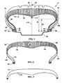
- Figure 1 depicts, in radial section, part of a tyre according to an embodiment of the invention
- Figures 2 to 5 depict details of the chamber of the tyre of figure 1 and of an alternative embodiment
- Figures 6 to 8 depict, in radial section, tyres according to embodiments of the invention.
- FIG 1 schematically depicts, viewed in radial section, part of a tyre 11 according to an embodiment of the invention mounted on a mounting rim 20.
- the tyre 11 comprises two beads 30, each bead comprising an annular reinforcing structure 40 (here, a bead wire) and a seat 50 configured to come into contact with the mounting rim 20, a crown 60 comprising a crown reinforcing armature (not depicted) surmounted by a tread, two sidewalls 70, each sidewall 70 extending between a bead 30 and the crown 60, and a radial carcass reinforcing armature 80 comprising reinforcement elements in the form of substantially mutually parallel nylon threads.
- thread is to be understood in a very broad sense and encompasses threads in the form of monofilaments, multifilaments, a cable, a yarn or an equivalent assembly, irrespective of the material of which the thread is made or of the surface treatment applied to encourage it to bond with the rubber or to make it stick.
- a thread or a reinforcing armature is said to be “radial” when the thread or the reinforcement elements of the reinforcing armature make an angle greater than or equal to 65° and less than or equal to 90° with respect to the circumferential direction.
- the carcass reinforcing armature 80 extends from one bead 30 to the other. It is anchored in each bead 30 to the annular reinforcing structure, here by winding end portion 85 around the bead wire 40.
- the tyre 11 further comprises a membrane 90.
- This membrane 90 comprises a membrane reinforcing armature 91 and an airtight rubber mix 94, here a butyl-based rubber mix.
- rubber mix denotes a rubber composition containing at least one elastomer and one filler.
- the membrane reinforcing armature 91 comprises a single layer of reinforcement elements (here, nylon threads) which is anchored in each bead 30 to the annular reinforcing structure by winding end portion 95 around the bead wire 40. Its reinforcement elements are substantially radial, i.e. they make an angle greater than or equal to 65° and less than or equal to 90° with respect to the circumferential direction.
- the membrane 90 is arranged in such a way that part of the membrane together with part of the carcass reinforcing armature 80 delimits a chamber 100 (i.e. parts of membrane 90 and carcass reinforcement 80 form the walls of chamber 100) extending transversely and circumferentially, this chamber 100 being situated radially on the inside of the carcass reinforcing armature 80 and, to a large extent, under the crown 60.
- the chamber 100 is completely filled with a self-sealing fluid such as CHS TM gel marketed by Inovex Industries Inc.
- a product or fluid is said to be "self-sealing” if it is capable of forming an airtight seal around the object that has punctured the membrane and of sealing the hole left by the object when this object has been removed.
- Self-sealing products are well known to those skilled in the art, for example from documents US 6,837,287 and EP 0 893 236 .
- a point P1 is said to be “radially inside” a point P2 (or “radially on the inside of” point P2) if it is closer to the axis of rotation of the tyre than point P2.
- a point P3 is said to be “radially outside” a point P4 (or “radially on the outside of” point P4) if it is further from the axis of rotation of the tyre than point P4.
- the embodiment depicted in Figure 1 has a significant advantage over a conventional self-sealing tyre.
- the sealing fluid under the effect of centrifugal force, covers only the radially outer part of the interior of the tyre. If there is a closed chamber and if this chamber is completely filled with sealing fluid, this fluid can barely move around even when the tyre is running and centrifugal force is applied. If, like here, the chamber 100 is sized in such a way that it also covers part of the sidewalls 70, then the sealing fluid is forced to remain in this region. If the sidewall is punctured at the radially outer part of the sidewall 70, this puncture can be sealed.
- the curved length Lm of the trace of the chamber 100 delimited by the membrane 90 is greater than the curved length Lc of the trace of the surface of the chamber 100 delimited by the carcass reinforcing armature 80, i.e. Lm > Lc.
- Lm the curved length of the trace of the surface of the chamber 100 delimited by the carcass reinforcing armature 80
- Lm the curved length of the trace of the surface of the chamber 100 delimited by the carcass reinforcing armature 80
- Lm > Lc Typically, a difference of the order of 1 to 10%, and more preferentially of 2 to 5% is aimed for.
- Figure 2 depicts a detail of Figure 1 in order to illustrate these geometric considerations.
- the trace of the chamber 100 has two parts which extend between the two points 101, near the sidewalls 70, radially furthest towards the inside of the chamber.
- the radially outer part is delimited by the carcass reinforcing armature 80, and it has a curved length Lc (see Figure 3 ).
- the radially inner part is delimited by the membrane 90 and has a curved length Lm (see Figure 3 ).
- the crown 60 When the crown 60 is punctured, for example by a small-diameter nail, and the nail is removed, the hole left by the nail is immediately sealed by the sealing fluid.
- the volume of the chamber 100 decreases accordingly by the reduction in volume of the sealing fluid and the inflation pressure of the tyre, but not enough for the membrane reinforcing armature 90 to begin to contribute to the operation of the carcass. Punctures such as this can be sustained repeatedly without the membrane reinforcing armature coming into play.
- the crown 60 (or the sidewall in the part covering the chamber 100) is torn or punctured in such a way that it has large-diameter holes (typically with diameters in excess of 5 mm)
- the sealing fluid escapes through the opening in the crown (or in the sidewall).
- the chamber empties and ultimately no longer contains any material capable, in conjunction with the carcass reinforcing armature 80, of balancing the inflation pressure.
- the inflation pressure of the tyre then has the effect of forcing the membrane 90 to fill the space previously occupied by the chamber 100. As a consequence, it begins to contribute to the working of the carcass of the tyre. This effect is applied to the full when the puncture is such that the integrity of the crown or of the sidewall is affected. At this stage, the membrane 90 becomes taut and takes over the role of the carcass.
- the tyre 11 is, therefore, able to provide an appropriate response to punctures of variable size, taking account of the severity of the damage with respect to the physical integrity of the crown 60 and part of the sidewall 70.
- the tyre 11 has the advantages of double chamber tyres in so far as when an object such as a nail punctures the tread of the tyre and comes to rest in the chamber 100 contained between the carcass reinforcing armature and the membrane, the tyre does not fully deflate.
- the tyre cavity (that is to say the volume between the membrane 90 of the tyre 11 and the rim 20) remains pressurized. The driver of the vehicle fitted with the tyre 11 can continue his journey.
- the tyre has significant advantages over known double chamber tyres.
- it has a membrane which is significantly less taut than the carcass reinforcing armature, or is even not taut at all in the region of contact between the membrane and the chamber.
- the membrane 90 does no work during normal running, and this has the advantage of extending the life of the membrane, and especially of making it less vulnerable to puncturing when the tyre is punctured.
- normal running is a mode of running in which the tyre is not punctured and is inflated to its service pressure, as opposed to "running in degraded mode".
- the membrane In the case of the double chamber tyres of the prior art, the membrane is generally under tension as soon as the tyre has been inflated to its service pressure (such is the case, for example, of the tyre disclosed in US 3,901,750 ), thus making the membrane more sensitive to cuts and damage.
- double chamber tyres are known in which the membrane is not under tension during normal running because the chamber formed between the membrane and the rim is not inflated (like the one in Patent US 3,087,528 ) but these tyres need to have the emergency chamber inflated after the tyre is punctured.
- the membrane 90 begins to play its part following a very large puncture, without there being any need to inflate the tyre.
- the tyre 11 has a valve 111 which in particular allows the chamber 100 to be filled with sealing fluid before the tyre 11 is mounted on the rim 20 and inflated to its service pressure, using a conventional tyre inflation valve which has not been depicted.
- the radial distance Dr between the seat of a bead and the radially innermost part 101 of the chamber 100 is equal to 0.45 times the height H of tyre on the mounting rim.
- the height H is measured between the seat 50 of the bead 30 and the radially outermost point 65 of the crown 60 in the mid-plane 110 of the tyre 11 when the tyre is mounted on the mounting rim 20 and inflated to the service pressure).
- the "mid-plane" 110 of the tyre is the plane normal to the axis of rotation of the tyre and which lies midway between the annular reinforcing structures 40 of each bead 30.
- the size E of the chamber 100 in a direction perpendicular both to the axis of rotation of the tyre and to the circumferential direction is greater than 5 mm at every point, except perhaps at the axial ends of the chamber 100.
- FIG. 6 schematically depicts, viewed in radial section, part of another tyre 12 according to an embodiment of the invention.
- the tyre 12 comprises a membrane 90 the reinforcing armature of which comprises a first layer of nylon reinforcement elements 91 and a second layer of nylon reinforcement elements 92, each of these layers having mutually parallel reinforcement elements, the reinforcement elements of one layer crossing with those of the other layer.
- the reinforcement elements in the first layer of reinforcement elements 91 make an angle of 45° with respect to the mid-plane 110 of the tyre, those of the second layer of reinforcement elements 92 make an angle of -45°.
- the radial distance Dr between the seat of a bead and the radially innermost part 102 of the chamber 100 is equal to 0.6 times H.
- the chamber 100 has a size E, in a direction perpendicular both to the axis of rotation of the tyre and to the circumferential direction, that is greater than or equal to 2 mm over practically all of its axial extent.
- the valve 112 for filling the chamber 100 is positioned on the exterior surface of one of the sidewalls 70, which allows the chamber 100 to be inflated after the tyre 12 has been inflated.
- the compression of the reinforcement elements of the carcass reinforcing armature can be varied.
- the membrane 90 of the tyre 12 of Figure 6 bulges radially inwards.
- the chamber 100 of the tyre 12 is not symmetric with respect to the mid-plane 110 (see Figure 1 ) of the tyre. This fact is not in any way connected with the other features of the tyre 12 but is one possible alternative way of designing the chamber 100. However, except in special applications, attempts will be made to obtain a chamber 100 which is symmetric with respect to the mid-plane 110.
- Figure 7 schematically depicts a tyre 13 according to an embodiment of the invention in which the chamber 100 is only partially filled with sealing fluid 120.
- the remainder of the chamber is filled with inflation gas 130 (here, air) under pressure, the inflation pressure of the chamber 100 being substantially equal to the service pressure of the tyre 13.
- the air 130 is pressurized simply by inflating the tyre 13 to its service pressure. As long as the air 130 contained in the chamber 100 is not pressurized to the inflation pressure of the tyre 13, the volume of the chamber 100 decreases during inflation.
- the membrane 90 begins to contribute to the work done by the carcass, provided that the sealing fluid occupies a significant enough portion of the volume of the chamber and/or provided that the amount of air 130 contained in the chamber prior to inflation of the tyre 13 is enough for this quantity of air, when pressurized to the service pressure of the tyre 13, to occupy a sufficiently large volume.
- the distribution of the sealing fluid 120 and of the inflation gas 130 that has been depicted in Figure 7 is purely schematic. The true distribution will depend in particular on the viscosity of the sealing fluid 120 and above all on the speed at which the tyre is running. When the tyre is running at high speed, the sealing fluid will have a tendency to occupy the radially outer part of the chamber 100.
- the chamber As the chamber is configured to contain air, it is provided with a layer of airtight rubber mix 942.
- a second layer of airtight rubber mix 941 is applied to the membrane, but in contrast with the tyre 11 of Figure 1 , on the chamber side.
- This arrangement results in greater ease of manufacture because the layers of airtight rubber mix are applied in succession and are not separated by other layers. Given that most airtight rubber mixes are incompatible with the other rubber mixes customarily used in tyres and that it is, as far as possible, desirable to separate these rubber mixes from the other mixes, this is a considerable advantage from the manufacturing standpoint.
- FIG. 8 schematically depicts a fourth tyre 14 according to an embodiment of the invention.
- the carcass reinforcing armature here comprises a first layer of reinforcement elements 81 which, in each bead 30 is wound around the bead wire 40, and a second layer of reinforcement elements 82 which is, in a way known per se, superposed onto the first layer of reinforcement elements 81.
- the membrane 90 has a reinforcing armature which also comprises two layers of reinforcement elements 91 and 92 which are both anchored onto the bead wire 40 in each of the beads 30.
- the tyre comprises a conventional inner liner 94 made of an airtight rubber mix.
- the radially outer part of the chamber 100 is also covered with a layer 942 of airtight rubber mix.
- This layer 942 is needed because the chamber here is filled only with air and a small amount of lubricating liquid.
- lubricants described in patent US 2,987,093 , such as silicone oils, castor oil, olive oil, etc.
- the chamber 100 is filled with an appropriate amount of air to give the chamber its final volume when the pressure in the chamber will have reached the tyre service pressure.
- the air is introduced into the chamber 100 through the valve 111 (which could of course have been provided on a sidewall 70 of the tyre 10).
- the tyre is mounted on the rim 20 and inflated to its service pressure. If the crown of the tyre is punctured, the chamber 100 empties of the air and thus allows the membrane 90 to fill the space previously occupied by the chamber 100, the consequence of this being that the membrane begins to contribute to work done by the carcass.
- the fluid or fluids with which the chamber is filled is that of preventing the membrane 90, under the influence of the tyre inflation pressure, from completely filling the space occupied by the chamber 100 and beginning to act as a second carcass.
- this fluid or these fluids leave the chamber and thus cause the membrane to begin to contribute to the work of the carcass.
- the fluid is an incompressible liquid, but it may equally be a gas in sufficient quantity that, when the tyre is inflated to its service pressure, the volume that the gas occupies when the pressure in the chamber 100 is identical to that of the cavity of the tyre is high enough for the membrane 90 not to begin to become taut. It is also possible to inflate the tyre initially (which will bring the membrane 90 into close contact with the carcass while the chamber 100 is empty) and to inflate the chamber 100 afterwards.
- the present invention relates to a method of manufacturing a tyre having a structure as defined in claim 1. It is possible to obtain a tyre as defined in claim 1 by using a conventional manufacturing process, such as is disclosed in U.S. Patent No. 3,819,791 . In such a process, the raw tyre is inserted into a mould heated by superheated water and steam. The water circulates continuously in a membrane ("curing membrane", to be distinguished from the membrane 90 of the tyre) which is inside the raw tyre and which is inflated at the beginning of the curing process.
- a membrane to be distinguished from the membrane 90 of the tyre
- the curing membrane As the curing membrane expands inside the tyre, it pushes the tyre against the hot mould walls, thus ensuring the moulding of the tyre tread design. Curing lasts for about 10 minutes (for ordinary tyres). At the end of the curing process, the curing membrane is deflated and the tyre can be taken out of the mould. Fitting the membrane 90 makes manufacture significantly more complex.
- the membrane 90 may have a tendency to fold up in a poorly controlled way while the curing membrane is inflated and may, after curing, find itself fixed in an inappropriate way.
- This disadvantage can be avoided by at least partially curing the tyre beforehand without the membrane and then vulcanizing the membrane onto it, but the need to anchor the membrane in the bead makes this alternative method laborious and technically tricky.
- another aspect of the present invention is directed to a tyre manufacturing method whereby the carcass reinforcement elements and the membrane reinforcement elements are chosen in such a way that, prior to manufacture of the tyre, the "high-temperature contraction potential" CC C of the carcass reinforcement elements is greater than the high-temperature contraction potential CC M of the membrane reinforcement elements.
- CC high-temperature contraction potential
- CC means here is the relative variation in length of a reinforcement element positioned, under a pretension of 0.2 cN/tex (remember that 1 cN/tex is equal to 0.11 gram/denier) between the plates of a heater (device of the Testrite type) set to a constant temperature of 185 ⁇ 0.5°C.
- the length L 1 is measured after the reinforcement element has stabilized at the temperature of 185°C for 120 s ⁇ 2%.
- the high-temperature contraction potential is the consequence of the impact of all the operations that the reinforcement element has experienced during its production or its implementation.
- the standard high-temperature contraction potential is usually used to characterize textile reinforcement elements but can be extended to cover metals. It should be noted that the standard high-temperature contraction potential, as defined above, will have a positive magnitude for textiles whereas in the case of metals, thermal expansion is observed when the temperature increases, leading to negative values of the standard high-temperature contraction potential as defined above.
- the high-temperature contraction potential CC C of the carcass reinforcement elements is important for the high-temperature contraction potential CC M of the membrane reinforcement elements.
- This can be achieved by using appropriate textile reinforcement elements both in the carcass reinforcing armature and in the membrane reinforcing armature.
- the reinforcement elements in the carcass reinforcing armature contract more than the reinforcement elements in the membrane reinforcing armature, causing the reinforcement elements in the membrane reinforcing armature to be placed under compression.
- the membrane reinforcing armature therefore finds itself trapped between the carcass reinforcing armature and the curing membrane, but as soon as the curing membrane is deflated, the membrane of the tyre will have a tendency to detach itself from the carcass reinforcing armature, thus causing a chamber to be formed between the tyre membrane and the carcass reinforcing armature of this tyre. The chamber remains even after the tyre has cooled.
- the chamber is filled with the inflation gas and/or with the sealing fluid. It would theoretically be possible to inject the sealing fluid while the tyre is curing, but it is preferable to do so after curing.
- the fluid could be injected using a syringe, but it is advantageous to provide a filling valve. This valve may be provided on the inside of the tyre or on a sidewall thereof. It may be fitted before or after curing, by adhesive bonding, in the manner of a repair patch.
- This method therefore makes it possible to obtain a tyre as defined in claim 1 by using traditional manufacturing methods, whereas the manufacture of double chamber tyres of the prior art requires a multi-step manufacture or even requires the assembly of a traditional tyre with an insert. Because of the difference in high-temperature contraction potential between the carcass reinforcing armature and the membrane reinforcing armature, a chamber is obtained quite naturally when the tyre is cured in a traditional mould and then cooled.
- the method of manufacturing according to the invention is distinguished from the method according to document US 3,004,579 in that, prior to manufacture of the tyre, the high-temperature contraction potential of the carcass reinforcement elements is greater than the high-temperature contraction potential of the membrane reinforcement elements.
- This inversion is, nevertheless, not straightforward, because those of ordinary skill in the art would have hesitated to use carcass reinforcement elements having a high-temperature contraction potential that is greater than the high-temperature contraction potential of the membrane reinforcement elements.
- those of ordinary skill in the art would have feared that a significant contraction of the carcass reinforcement elements during the curing process would result in a displacement of the carcass reinforcement elements or even a complete dislocation of the tyre architecture in the mould.
Landscapes
- Engineering & Computer Science (AREA)
- Mechanical Engineering (AREA)
- Tyre Moulding (AREA)
- Tires In General (AREA)
- Rolls And Other Rotary Bodies (AREA)
- Machines For Manufacturing Corrugated Board In Mechanical Paper-Making Processes (AREA)
- Making Paper Articles (AREA)
Applications Claiming Priority (3)
| Application Number | Priority Date | Filing Date | Title |
|---|---|---|---|
| FR0708069A FR2923750B1 (fr) | 2007-11-16 | 2007-11-16 | Pneumatique capable de rouler malgre une perforation,et procede pour sa fabrication. |
| US6701908P | 2008-02-25 | 2008-02-25 | |
| PCT/EP2008/009655 WO2009062736A1 (en) | 2007-11-16 | 2008-11-14 | Tyre capable of running in spite of being punctured, and method for manufacturing it |
Publications (2)
| Publication Number | Publication Date |
|---|---|
| EP2222484A1 EP2222484A1 (en) | 2010-09-01 |
| EP2222484B1 true EP2222484B1 (en) | 2011-06-29 |
Family
ID=39316402
Family Applications (1)
| Application Number | Title | Priority Date | Filing Date |
|---|---|---|---|
| EP08850075A Not-in-force EP2222484B1 (en) | 2007-11-16 | 2008-11-14 | Method of manufacturing a double chamber tyre |
Country Status (10)
| Country | Link |
|---|---|
| US (1) | US8469070B2 (enExample) |
| EP (1) | EP2222484B1 (enExample) |
| JP (1) | JP5425800B2 (enExample) |
| AT (1) | ATE514577T1 (enExample) |
| AU (1) | AU2008323155B2 (enExample) |
| BR (1) | BRPI0820173A8 (enExample) |
| FR (1) | FR2923750B1 (enExample) |
| MX (1) | MX2010005380A (enExample) |
| NZ (1) | NZ585279A (enExample) |
| WO (1) | WO2009062736A1 (enExample) |
Families Citing this family (10)
| Publication number | Priority date | Publication date | Assignee | Title |
|---|---|---|---|---|
| CA2866233A1 (en) * | 2012-03-06 | 2013-09-12 | Smitiparna SATPATHY | Multi-chambered tubeless tyre and tube with/without sealant and manufacturing process for the same |
| KR101348323B1 (ko) | 2012-08-23 | 2014-01-09 | 현대중공업 주식회사 | 에어쿠션을 이용한 작업용 스카폴드 |
| JP6483395B2 (ja) * | 2014-10-15 | 2019-03-13 | 株式会社ブリヂストン | 空気入りタイヤ |
| EP3524447A1 (en) * | 2014-12-03 | 2019-08-14 | Bridgestone Americas Tire Operations, LLC | Rapid tire inflation method |
| FR3060462A1 (fr) * | 2016-12-16 | 2018-06-22 | Compagnie Generale Des Etablissements Michelin | Ensemble de bandage pneumatique et de roue comprenant un produit auto-obturant ameliore |
| GB2575269A (en) * | 2018-07-03 | 2020-01-08 | Automotive Fusion Ltd | Tyre |
| CN109159627B (zh) * | 2018-10-29 | 2023-12-19 | 朱爱军 | 一种八腔汽车防爆轮胎及配套轮毂 |
| CN109532336A (zh) * | 2019-01-03 | 2019-03-29 | 安徽世界村新材料有限公司 | 一种可充气防爆轮胎及其加工方法 |
| JP7287073B2 (ja) * | 2019-04-04 | 2023-06-06 | 横浜ゴム株式会社 | 自動二輪車用タイヤ |
| JP7692272B2 (ja) * | 2020-02-07 | 2025-06-13 | ザ・グッドイヤー・タイヤ・アンド・ラバー・カンパニー | 空気入りタイヤ |
Family Cites Families (17)
| Publication number | Priority date | Publication date | Assignee | Title |
|---|---|---|---|---|
| US616516A (en) | 1898-12-27 | Pneumatic tire | ||
| FR537859A (fr) * | 1921-06-14 | 1922-05-31 | Bandage à double chambre superposée l'une constituant <creux> et l'autre | |
| GB735882A (en) * | 1951-10-24 | 1955-08-31 | Firestone Tire & Rubber Co | Improvements in pneumatic tire |
| US3018813A (en) | 1958-01-28 | 1962-01-30 | Firestone Tire & Rubber Co | Diaphragm for tubeless tires |
| US3112790A (en) | 1958-05-29 | 1963-12-03 | Minnesota Mining & Mfg | Control systems |
| US3004579A (en) * | 1959-06-22 | 1961-10-17 | Gen Tire & Rubber Co | Process of making a dual chamber pneumatic tire and the tire so made |
| ZA712903B (en) * | 1970-05-27 | 1972-01-26 | Gen Tire & Rubber Co | Dual chambered tires |
| US4293017A (en) * | 1977-12-01 | 1981-10-06 | Lambe Donald M | Dual-chamber pneumatic tire |
| JPH045030A (ja) * | 1990-04-23 | 1992-01-09 | Bridgestone Corp | 空気入りタイヤ |
| JPH04368203A (ja) * | 1991-06-17 | 1992-12-21 | Toyota Motor Corp | 液封タイヤ |
| JPH0672103A (ja) * | 1992-08-27 | 1994-03-15 | Bridgestone Corp | 空気入りタイヤ |
| JP4368203B2 (ja) * | 1997-01-10 | 2009-11-18 | カシオ計算機株式会社 | 撮像装置および撮像画像加工方法 |
| JP3927308B2 (ja) * | 1998-03-05 | 2007-06-06 | 株式会社ブリヂストン | 自己アンバランス修正機構を具備したタイヤ |
| JP3510811B2 (ja) * | 1999-02-26 | 2004-03-29 | 住友ゴム工業株式会社 | 空気入りタイヤ |
| US6112790A (en) * | 1999-03-17 | 2000-09-05 | Taiwan Kings Glory Co., Ltd. | Puncture-durable tire structure |
| JP4191315B2 (ja) * | 1999-05-10 | 2008-12-03 | 本田技研工業株式会社 | シール剤入りタイヤ |
| DE10025079A1 (de) * | 2000-05-20 | 2001-11-29 | Continental Ag | Fahrzeugluftreifen |
-
2007
- 2007-11-16 FR FR0708069A patent/FR2923750B1/fr not_active Expired - Fee Related
-
2008
- 2008-11-14 US US12/743,346 patent/US8469070B2/en not_active Expired - Fee Related
- 2008-11-14 AT AT08850075T patent/ATE514577T1/de not_active IP Right Cessation
- 2008-11-14 WO PCT/EP2008/009655 patent/WO2009062736A1/en not_active Ceased
- 2008-11-14 AU AU2008323155A patent/AU2008323155B2/en not_active Ceased
- 2008-11-14 NZ NZ585279A patent/NZ585279A/en not_active IP Right Cessation
- 2008-11-14 EP EP08850075A patent/EP2222484B1/en not_active Not-in-force
- 2008-11-14 BR BRPI0820173A patent/BRPI0820173A8/pt not_active Application Discontinuation
- 2008-11-14 JP JP2010533502A patent/JP5425800B2/ja not_active Expired - Fee Related
- 2008-11-14 MX MX2010005380A patent/MX2010005380A/es active IP Right Grant
Also Published As
| Publication number | Publication date |
|---|---|
| MX2010005380A (es) | 2010-06-01 |
| BRPI0820173A8 (pt) | 2018-01-02 |
| NZ585279A (en) | 2011-12-22 |
| BRPI0820173A2 (pt) | 2017-05-09 |
| AU2008323155A1 (en) | 2009-05-22 |
| FR2923750B1 (fr) | 2011-03-18 |
| JP2011502872A (ja) | 2011-01-27 |
| US8469070B2 (en) | 2013-06-25 |
| WO2009062736A1 (en) | 2009-05-22 |
| JP5425800B2 (ja) | 2014-02-26 |
| FR2923750A1 (fr) | 2009-05-22 |
| EP2222484A1 (en) | 2010-09-01 |
| US20110284142A1 (en) | 2011-11-24 |
| AU2008323155B2 (en) | 2012-12-06 |
| ATE514577T1 (de) | 2011-07-15 |
Similar Documents
| Publication | Publication Date | Title |
|---|---|---|
| EP2222484B1 (en) | Method of manufacturing a double chamber tyre | |
| US4153095A (en) | Pneumatic tire having a pneumatic safety insert with beads | |
| EP3431309B1 (en) | Pneumatic tire | |
| JP5280104B2 (ja) | 転動時騒音減少型タイヤ | |
| EP2271480B1 (en) | Sealant material composition, self-sealing pneumatic tire, and preparation thereof | |
| JP2009537386A (ja) | タイヤ圧力調整のための形状記憶を有するチャンバー | |
| CS251051B2 (en) | Pneumatic tyre for motor vehicle's wheel | |
| RU2230672C2 (ru) | Колесо с шиной для транспортных средств | |
| US9365081B2 (en) | Pneumatic tire security system employing internal high pressure air bag | |
| JP4342724B2 (ja) | トレッドの支持膜 | |
| JP2001523607A (ja) | タイヤのエアチューブ及びその製造方法 | |
| RU2211764C2 (ru) | Камера для шины и способ ее изготовления | |
| US6557604B2 (en) | Safety liner for a vehicle tire and method of use | |
| CN104203598A (zh) | 包括增宽的胎面的轮胎 | |
| CN100513209C (zh) | 泄气时作为轮胎支撑的内体和装有这种内体的轮胎组件 | |
| US20060096687A1 (en) | Tubeless pneumatic tire, and method of making same | |
| JP2011521847A (ja) | インナーチューブ及びその製造方法 | |
| US6892777B2 (en) | Rim with seats inclined outwards and assemblies comprising such a rim and an inflated bearing support | |
| JP2002362118A (ja) | 空気入りタイヤおよびその製造方法 | |
| EP2177379B1 (en) | Safety tire | |
| JP2019018800A (ja) | 空気入りタイヤ及びその製造方法 | |
| JP2018514462A (ja) | 耐離座性の高いタイヤ | |
| JP2002192923A (ja) | 安全空気入りタイヤ | |
| JPH0253602A (ja) | パンクレスタイヤ・ホイール組立体 | |
| CN106715156A (zh) | 具有更好防脱圈性能的轮胎 |
Legal Events
| Date | Code | Title | Description |
|---|---|---|---|
| PUAI | Public reference made under article 153(3) epc to a published international application that has entered the european phase |
Free format text: ORIGINAL CODE: 0009012 |
|
| 17P | Request for examination filed |
Effective date: 20100616 |
|
| AK | Designated contracting states |
Kind code of ref document: A1 Designated state(s): AT BE BG CH CY CZ DE DK EE ES FI FR GB GR HR HU IE IS IT LI LT LU LV MC MT NL NO PL PT RO SE SI SK TR |
|
| AX | Request for extension of the european patent |
Extension state: AL BA MK RS |
|
| RTI1 | Title (correction) |
Free format text: METHOD OF MANUFACTURING A DOUBLE CHAMBER TYRE |
|
| GRAP | Despatch of communication of intention to grant a patent |
Free format text: ORIGINAL CODE: EPIDOSNIGR1 |
|
| DAX | Request for extension of the european patent (deleted) | ||
| GRAS | Grant fee paid |
Free format text: ORIGINAL CODE: EPIDOSNIGR3 |
|
| GRAA | (expected) grant |
Free format text: ORIGINAL CODE: 0009210 |
|
| AK | Designated contracting states |
Kind code of ref document: B1 Designated state(s): AT BE BG CH CY CZ DE DK EE ES FI FR GB GR HR HU IE IS IT LI LT LU LV MC MT NL NO PL PT RO SE SI SK TR |
|
| REG | Reference to a national code |
Ref country code: GB Ref legal event code: FG4D |
|
| REG | Reference to a national code |
Ref country code: CH Ref legal event code: EP |
|
| REG | Reference to a national code |
Ref country code: IE Ref legal event code: FG4D |
|
| REG | Reference to a national code |
Ref country code: DE Ref legal event code: R096 Ref document number: 602008007993 Country of ref document: DE Effective date: 20110818 |
|
| REG | Reference to a national code |
Ref country code: NL Ref legal event code: VDEP Effective date: 20110629 |
|
| PG25 | Lapsed in a contracting state [announced via postgrant information from national office to epo] |
Ref country code: SE Free format text: LAPSE BECAUSE OF FAILURE TO SUBMIT A TRANSLATION OF THE DESCRIPTION OR TO PAY THE FEE WITHIN THE PRESCRIBED TIME-LIMIT Effective date: 20110629 Ref country code: NO Free format text: LAPSE BECAUSE OF FAILURE TO SUBMIT A TRANSLATION OF THE DESCRIPTION OR TO PAY THE FEE WITHIN THE PRESCRIBED TIME-LIMIT Effective date: 20110929 Ref country code: HR Free format text: LAPSE BECAUSE OF FAILURE TO SUBMIT A TRANSLATION OF THE DESCRIPTION OR TO PAY THE FEE WITHIN THE PRESCRIBED TIME-LIMIT Effective date: 20110629 Ref country code: LT Free format text: LAPSE BECAUSE OF FAILURE TO SUBMIT A TRANSLATION OF THE DESCRIPTION OR TO PAY THE FEE WITHIN THE PRESCRIBED TIME-LIMIT Effective date: 20110629 |
|
| PG25 | Lapsed in a contracting state [announced via postgrant information from national office to epo] |
Ref country code: FI Free format text: LAPSE BECAUSE OF FAILURE TO SUBMIT A TRANSLATION OF THE DESCRIPTION OR TO PAY THE FEE WITHIN THE PRESCRIBED TIME-LIMIT Effective date: 20110629 Ref country code: AT Free format text: LAPSE BECAUSE OF FAILURE TO SUBMIT A TRANSLATION OF THE DESCRIPTION OR TO PAY THE FEE WITHIN THE PRESCRIBED TIME-LIMIT Effective date: 20110629 Ref country code: LV Free format text: LAPSE BECAUSE OF FAILURE TO SUBMIT A TRANSLATION OF THE DESCRIPTION OR TO PAY THE FEE WITHIN THE PRESCRIBED TIME-LIMIT Effective date: 20110629 Ref country code: GR Free format text: LAPSE BECAUSE OF FAILURE TO SUBMIT A TRANSLATION OF THE DESCRIPTION OR TO PAY THE FEE WITHIN THE PRESCRIBED TIME-LIMIT Effective date: 20110930 Ref country code: SI Free format text: LAPSE BECAUSE OF FAILURE TO SUBMIT A TRANSLATION OF THE DESCRIPTION OR TO PAY THE FEE WITHIN THE PRESCRIBED TIME-LIMIT Effective date: 20110629 |
|
| PG25 | Lapsed in a contracting state [announced via postgrant information from national office to epo] |
Ref country code: BE Free format text: LAPSE BECAUSE OF FAILURE TO SUBMIT A TRANSLATION OF THE DESCRIPTION OR TO PAY THE FEE WITHIN THE PRESCRIBED TIME-LIMIT Effective date: 20110629 |
|
| PG25 | Lapsed in a contracting state [announced via postgrant information from national office to epo] |
Ref country code: NL Free format text: LAPSE BECAUSE OF FAILURE TO SUBMIT A TRANSLATION OF THE DESCRIPTION OR TO PAY THE FEE WITHIN THE PRESCRIBED TIME-LIMIT Effective date: 20110629 Ref country code: PT Free format text: LAPSE BECAUSE OF FAILURE TO SUBMIT A TRANSLATION OF THE DESCRIPTION OR TO PAY THE FEE WITHIN THE PRESCRIBED TIME-LIMIT Effective date: 20111031 Ref country code: EE Free format text: LAPSE BECAUSE OF FAILURE TO SUBMIT A TRANSLATION OF THE DESCRIPTION OR TO PAY THE FEE WITHIN THE PRESCRIBED TIME-LIMIT Effective date: 20110629 Ref country code: CZ Free format text: LAPSE BECAUSE OF FAILURE TO SUBMIT A TRANSLATION OF THE DESCRIPTION OR TO PAY THE FEE WITHIN THE PRESCRIBED TIME-LIMIT Effective date: 20110629 Ref country code: IS Free format text: LAPSE BECAUSE OF FAILURE TO SUBMIT A TRANSLATION OF THE DESCRIPTION OR TO PAY THE FEE WITHIN THE PRESCRIBED TIME-LIMIT Effective date: 20111029 |
|
| PG25 | Lapsed in a contracting state [announced via postgrant information from national office to epo] |
Ref country code: PL Free format text: LAPSE BECAUSE OF FAILURE TO SUBMIT A TRANSLATION OF THE DESCRIPTION OR TO PAY THE FEE WITHIN THE PRESCRIBED TIME-LIMIT Effective date: 20110629 Ref country code: SK Free format text: LAPSE BECAUSE OF FAILURE TO SUBMIT A TRANSLATION OF THE DESCRIPTION OR TO PAY THE FEE WITHIN THE PRESCRIBED TIME-LIMIT Effective date: 20110629 Ref country code: RO Free format text: LAPSE BECAUSE OF FAILURE TO SUBMIT A TRANSLATION OF THE DESCRIPTION OR TO PAY THE FEE WITHIN THE PRESCRIBED TIME-LIMIT Effective date: 20110629 Ref country code: CY Free format text: LAPSE BECAUSE OF FAILURE TO SUBMIT A TRANSLATION OF THE DESCRIPTION OR TO PAY THE FEE WITHIN THE PRESCRIBED TIME-LIMIT Effective date: 20110629 |
|
| PLBE | No opposition filed within time limit |
Free format text: ORIGINAL CODE: 0009261 |
|
| STAA | Information on the status of an ep patent application or granted ep patent |
Free format text: STATUS: NO OPPOSITION FILED WITHIN TIME LIMIT |
|
| 26N | No opposition filed |
Effective date: 20120330 |
|
| PG25 | Lapsed in a contracting state [announced via postgrant information from national office to epo] |
Ref country code: MC Free format text: LAPSE BECAUSE OF NON-PAYMENT OF DUE FEES Effective date: 20111130 Ref country code: DK Free format text: LAPSE BECAUSE OF FAILURE TO SUBMIT A TRANSLATION OF THE DESCRIPTION OR TO PAY THE FEE WITHIN THE PRESCRIBED TIME-LIMIT Effective date: 20110629 |
|
| REG | Reference to a national code |
Ref country code: DE Ref legal event code: R097 Ref document number: 602008007993 Country of ref document: DE Effective date: 20120330 |
|
| REG | Reference to a national code |
Ref country code: IE Ref legal event code: MM4A |
|
| PG25 | Lapsed in a contracting state [announced via postgrant information from national office to epo] |
Ref country code: IE Free format text: LAPSE BECAUSE OF NON-PAYMENT OF DUE FEES Effective date: 20111114 |
|
| PG25 | Lapsed in a contracting state [announced via postgrant information from national office to epo] |
Ref country code: MT Free format text: LAPSE BECAUSE OF FAILURE TO SUBMIT A TRANSLATION OF THE DESCRIPTION OR TO PAY THE FEE WITHIN THE PRESCRIBED TIME-LIMIT Effective date: 20110629 |
|
| PG25 | Lapsed in a contracting state [announced via postgrant information from national office to epo] |
Ref country code: ES Free format text: LAPSE BECAUSE OF FAILURE TO SUBMIT A TRANSLATION OF THE DESCRIPTION OR TO PAY THE FEE WITHIN THE PRESCRIBED TIME-LIMIT Effective date: 20111010 |
|
| PG25 | Lapsed in a contracting state [announced via postgrant information from national office to epo] |
Ref country code: LU Free format text: LAPSE BECAUSE OF NON-PAYMENT OF DUE FEES Effective date: 20111114 |
|
| PG25 | Lapsed in a contracting state [announced via postgrant information from national office to epo] |
Ref country code: BG Free format text: LAPSE BECAUSE OF FAILURE TO SUBMIT A TRANSLATION OF THE DESCRIPTION OR TO PAY THE FEE WITHIN THE PRESCRIBED TIME-LIMIT Effective date: 20110929 |
|
| REG | Reference to a national code |
Ref country code: CH Ref legal event code: PL |
|
| GBPC | Gb: european patent ceased through non-payment of renewal fee |
Effective date: 20121114 |
|
| PG25 | Lapsed in a contracting state [announced via postgrant information from national office to epo] |
Ref country code: CH Free format text: LAPSE BECAUSE OF NON-PAYMENT OF DUE FEES Effective date: 20121130 Ref country code: LI Free format text: LAPSE BECAUSE OF NON-PAYMENT OF DUE FEES Effective date: 20121130 |
|
| PG25 | Lapsed in a contracting state [announced via postgrant information from national office to epo] |
Ref country code: TR Free format text: LAPSE BECAUSE OF FAILURE TO SUBMIT A TRANSLATION OF THE DESCRIPTION OR TO PAY THE FEE WITHIN THE PRESCRIBED TIME-LIMIT Effective date: 20110629 |
|
| PG25 | Lapsed in a contracting state [announced via postgrant information from national office to epo] |
Ref country code: HU Free format text: LAPSE BECAUSE OF FAILURE TO SUBMIT A TRANSLATION OF THE DESCRIPTION OR TO PAY THE FEE WITHIN THE PRESCRIBED TIME-LIMIT Effective date: 20110629 |
|
| PG25 | Lapsed in a contracting state [announced via postgrant information from national office to epo] |
Ref country code: GB Free format text: LAPSE BECAUSE OF NON-PAYMENT OF DUE FEES Effective date: 20121114 |
|
| REG | Reference to a national code |
Ref country code: FR Ref legal event code: PLFP Year of fee payment: 8 |
|
| REG | Reference to a national code |
Ref country code: FR Ref legal event code: PLFP Year of fee payment: 9 |
|
| REG | Reference to a national code |
Ref country code: FR Ref legal event code: PLFP Year of fee payment: 10 |
|
| PGFP | Annual fee paid to national office [announced via postgrant information from national office to epo] |
Ref country code: DE Payment date: 20181120 Year of fee payment: 11 |
|
| PGFP | Annual fee paid to national office [announced via postgrant information from national office to epo] |
Ref country code: IT Payment date: 20181126 Year of fee payment: 11 Ref country code: FR Payment date: 20181123 Year of fee payment: 11 |
|
| REG | Reference to a national code |
Ref country code: DE Ref legal event code: R119 Ref document number: 602008007993 Country of ref document: DE |
|
| PG25 | Lapsed in a contracting state [announced via postgrant information from national office to epo] |
Ref country code: IT Free format text: LAPSE BECAUSE OF NON-PAYMENT OF DUE FEES Effective date: 20191114 Ref country code: FR Free format text: LAPSE BECAUSE OF NON-PAYMENT OF DUE FEES Effective date: 20191130 Ref country code: DE Free format text: LAPSE BECAUSE OF NON-PAYMENT OF DUE FEES Effective date: 20200603 |