US4153095A - Pneumatic tire having a pneumatic safety insert with beads - Google Patents
Pneumatic tire having a pneumatic safety insert with beads Download PDFInfo
- Publication number
- US4153095A US4153095A US05/833,109 US83310977A US4153095A US 4153095 A US4153095 A US 4153095A US 83310977 A US83310977 A US 83310977A US 4153095 A US4153095 A US 4153095A
- Authority
- US
- United States
- Prior art keywords
- insert
- tire
- beads
- pneumatic
- support surface
- Prior art date
- Legal status (The legal status is an assumption and is not a legal conclusion. Google has not performed a legal analysis and makes no representation as to the accuracy of the status listed.)
- Expired - Lifetime
Links
Images


Classifications
-
- B—PERFORMING OPERATIONS; TRANSPORTING
- B60—VEHICLES IN GENERAL
- B60C—VEHICLE TYRES; TYRE INFLATION; TYRE CHANGING; CONNECTING VALVES TO INFLATABLE ELASTIC BODIES IN GENERAL; DEVICES OR ARRANGEMENTS RELATED TO TYRES
- B60C17/00—Tyres characterised by means enabling restricted operation in damaged or deflated condition; Accessories therefor
- B60C17/01—Tyres characterised by means enabling restricted operation in damaged or deflated condition; Accessories therefor utilising additional inflatable supports which become load-supporting in emergency
-
- B—PERFORMING OPERATIONS; TRANSPORTING
- B60—VEHICLES IN GENERAL
- B60C—VEHICLE TYRES; TYRE INFLATION; TYRE CHANGING; CONNECTING VALVES TO INFLATABLE ELASTIC BODIES IN GENERAL; DEVICES OR ARRANGEMENTS RELATED TO TYRES
- B60C17/00—Tyres characterised by means enabling restricted operation in damaged or deflated condition; Accessories therefor
- B60C17/10—Internal lubrication
-
- B—PERFORMING OPERATIONS; TRANSPORTING
- B60—VEHICLES IN GENERAL
- B60C—VEHICLE TYRES; TYRE INFLATION; TYRE CHANGING; CONNECTING VALVES TO INFLATABLE ELASTIC BODIES IN GENERAL; DEVICES OR ARRANGEMENTS RELATED TO TYRES
- B60C5/00—Inflatable pneumatic tyres or inner tubes
- B60C5/20—Inflatable pneumatic tyres or inner tubes having multiple separate inflatable chambers
-
- B—PERFORMING OPERATIONS; TRANSPORTING
- B60—VEHICLES IN GENERAL
- B60C—VEHICLE TYRES; TYRE INFLATION; TYRE CHANGING; CONNECTING VALVES TO INFLATABLE ELASTIC BODIES IN GENERAL; DEVICES OR ARRANGEMENTS RELATED TO TYRES
- B60C19/00—Tyre parts or constructions not otherwise provided for
- B60C2019/006—Warning devices, e.g. devices generating noise due to flat or worn tyres
-
- Y—GENERAL TAGGING OF NEW TECHNOLOGICAL DEVELOPMENTS; GENERAL TAGGING OF CROSS-SECTIONAL TECHNOLOGIES SPANNING OVER SEVERAL SECTIONS OF THE IPC; TECHNICAL SUBJECTS COVERED BY FORMER USPC CROSS-REFERENCE ART COLLECTIONS [XRACs] AND DIGESTS
- Y10—TECHNICAL SUBJECTS COVERED BY FORMER USPC
- Y10T—TECHNICAL SUBJECTS COVERED BY FORMER US CLASSIFICATION
- Y10T152/00—Resilient tires and wheels
- Y10T152/10—Tires, resilient
- Y10T152/10495—Pneumatic tire or inner tube
- Y10T152/10666—Automatic sealing of punctures [e.g., self-healing, etc.]
- Y10T152/10675—Using flowable coating or composition
- Y10T152/10684—On inner surface of tubeless tire
Definitions
- This invention is directed to pneumatic tires with run-flat capabilities and more particularly to a pneumatic tire having a pneumatic safety insert with beads.
- One known tire of this type such as shown in British Pat. No. 808,481 requires a special rim for supporting a pneumatic tire and a pneumatic safety insert.
- the disclosed arrangement also requires spacer members between the tire and insert, or an insert bead retainer on the rim, to permit separate inflation of the insert air chamber and the tire air chamber to different pressure levels.
- Still another known tire of this type such as shown in U.S. Pat. No. 3,025,902 requires the tire beads to fit onto extensions of an insert to maintain an airtight inflation chamber within the insert. The forces borne by the tire beads during vehicle movement are thus transmitted to the insert risking damage to the insert before it must be depended upon.
- a novel safety tire incorporating a pneumatic insert with beads
- a novel safety tire and rim assembly that provides separate non-communicable inflation chambers for the tire and insert
- a novel safety tire and rim assembly wherein an airtight seal between a tire inflation chamber and an insert inflation chamber is maintained by flaps extending from beads on the pneumatic insert
- a novel safety tire and rim assembly that incorporates a standard tire and a standard rim
- a novel pneumatic insert for a safety tire is provided.
- the present invention relates to a novel safety tire incorporating a standard pneumatic tire and a separate pneumatic insert with beads having flaps extending therefrom, both of which can be mounted on a standard rim.
- the pneumatic insert which is positioned within the tire cavity, is formed as a generally toroidal-shaped hollow member having a pair of axially spaced apart insert beads arranged to bear against the tire beads and the rim.
- the insert bead diameter is preferably greater than the tire bead diameter.
- Each outer sidewall surface of the insert includes an annular flap portion extending beyond each insert bead. The flaps are tucked between the respective insert beads and the support surface of the rim and function as gasket seals between the insert beads and the support surface.
- the flaps also overlay the support surface and are pressed thereagainst by the air pressure within the insert inflation chamber to enhance the leak-tight seal of the insert against the rim support surface.
- a tire inflation chamber defined between the tire and the pneumatic insert is non-communicable with the insert inflation chamber.
- a first air valve member secured to the rim at the base of the wheel well inflates the pneumatic insert to spread the insert beads against the tire beads in substantially leak-tight surface to surface contact.
- a tire inflation chamber is thus defined between the tire and the pneumatic insert.
- An air passage channel formed in the support surface of the rim aligns with the plane of contact between one of the tire beads and one of the insert beads, thereby defining an air passage duct.
- An air passage fixture is sandwiched between the contacting tire and insert beads, in alignment with the air passage channel. The air passage fixture has at least one through opening communicating with the air passage duct and the tire inflation chamber.
- a second air valve member is secured to the rim at the base of the air passage channel, but not necessarily in alignment with the air passage fixture. Air entering the second air valve passes into the air passage duct and through the opening of the air passage fixture into the tire inflation chamber.
- the tire air chamber is inflated through a removable hypodermic needle inserted in the tire sidewall at a predetermined location that is backed with puncture sealant material.
- the air passage channel, the air passage fixture and the second valve member can thus be eliminated.
- the inner surface of the pneumatic insert can also include puncture sealant material and the outer crown surface can be layered with tear resistant fabric.
- a protective cap such as a filament wound material that prevents entry of nails into the pneumatic insert can also be provided on the insert crown. Suitable lubricants are provided between the insert and the tire.
- the air escaping from the tire inflation chamber causes the road contacting portion of the tire tread to flatten against the insert crown which provides support for the tread. Air does not escape from the insert air chamber because it does not normally communicate with the tire air chamber.
- the tire can thus be run in its flattened condition for approximately 45 miles at speeds exceeding 45 miles per hour, and longer distances at lower speeds.
- FIG. 1 is a sectional view showing a safety tire and rim assembly incorporating one embodiment of the present invention
- FIG. 2 is an enlarged fragmentary perspective view of a portion thereof
- FIG. 3 is a sectional view taken on the line 3--3 of FIG. 2;
- FIG. 4 shows a section of a pneumatic insert used in the assembly of FIG. 1;
- FIGS. 5 and 6 show other embodiments of the pneumatic insert of FIG. 4;
- FIGS. 7 and 8 show the tire and pneumatic insert being mounted on the rim
- FIG. 9 is a sectional view taken on the line 9--9 of FIG. 3;
- FIGS. 10 and 11 show the assembly before and after tire failure
- FIGS. 12 and 13 show other embodiments of the invention.
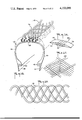
- FIG. 14 is a perspective view of an air passage member
- FIG. 15 shows another embodiment of the pneumatic insert with a filament wound protective cap
- FIG. 16 is a plan view of the protective cap of FIG. 15;
- FIG. 17 is another embodiment of a filament wound protective cap
- FIG. 18 shows the dynamics of a nail entering the safety tire and rim assembly
- FIGS. 19-22 show a lubrication system for the safety tire and rim assembly
- FIGS. 23 and 24 compare the dimensions of the safety tire and rim assembly before and after tire failure
- FIGS. 25 and 26 show run-flat warning devices incorporated in the pneumatic insert.
- FIGS. 27 and 28 are data graphs.
- the assembly 10 comprises a standard tubeless pneumatic tire 12, with a pneumatic insert member 14 both mounted on a standard one piece drop center rim 16.
- the pneumatic tire 12 includes spaced annular bead portions 18 and 20 with sidewalls 22 and 24 extending therefrom and a tread portion 26 bridging the sidewalls. Respective inner surfaces 28, 30 and 32 of the sidewalls 22, 24 and the tread 26 define a tire cavity 34. Unless otherwise indicated use of the term tire refers to an FR 78.14 tire.
- the pneumatic insert member 14 is of generally toroidal shape and comprises two fabric-reinforced rubber plies 36 and 38 (FIGS. 4 and 5) wrapped around annular insert beads 40 and 42 that are of smaller cross-section than the tire beads 18 and 20.
- the plies 36 and 38 thus define insert sidewalls 44 and 46, and an insert crown portion 48.
- the layers of fabric-reinforced rubber are arranged with the cords (not shown) in one layer intersecting the cords of another layer to form an angle in the range of approximately 30° to 90° with the equatorial plane of the tire.
- the carcass of the insert 14 thus resembles that of a small bias angle or radial pneumatic tire.
- the cords can be formed of rayon with a minimum tensile strength of 46 lbs. and 20 to 24 ends per inch to provide a breaking strength of approximately 920 to 1104 pounds per inch. Polyester with a tensile strength of from 47 to 50 lbs. and approximately 22 ends per inch can also be used, and provides a breaking strength of approximately 1034 to 1100 pounds per inch. Other types of fabric such as nylon or a high tensile strength polyamide sold under the designation Kevlar can be used as well.
- the insert member 14 further includes an outside cover 50 preferably formed of rubber that is less than 0.05 inches thick, an inner diffusion resistant liner 52 preferably formed of chlorobutyl that is less than 0.07 inches thick, and toe strips 54 and 56 around the insert beads 40 and 42. Further use of the term bead is generally intended to refer to the bead area.
- a pair of annular rings 58 and 60 henceforth called flaps are respectively joined to the outside surfaces of the insert sidewalls 44 and 46.
- the flaps 58 and 60 are preferably formed of rubber ranging in thickness from approximately 0.05 inches to 0.1 inches.
- the type of flap rubber used preferably has a high elongation at break, such as for example above 600% with a modulus at 300% elongation of at least 700 lbs. and a tensile strength of at least 2700 lbs. Lower range values can be used by varying the bead diameter and/or flap thickness.
- the inner diameter of the flaps 58 and 60 are preferably from 2 to 3 inches smaller than the diameter of the insert beads 40 and 42.
- the flaps 58 and 60 also preferably extend approximately 1.5 to 2 inches below the toe strips 54 and 56 (FIG. 4) and need not extend identical amounts.
- a layer of puncture sealant material such as disclosed in U.S. Pat. No. 3,981,342, coats the inside surface of the insert member 14.
- a tear resistant reinforcement 61 (FIG. 5) can be provided at the insert crown portion 48 extending into the insert sidewalls 44 and 46.
- the reinforcement 61 can comprise a fabric or wire belt, a high modulus rubber strip placed between the plies 36 and 38, any suitable known specially woven tear resistant fabric such as triaxially woven fabric or chafer fabric, floc-filled rubber covers or thermoplastic or polyurethane layers.
- the strength of the tear resistant material can be measured by penetrating the material with a nail with a diameter of 0.16 inches for example, and pulling the nail and material in opposite directions parallel to the plane of the material. The tearing force required to pull the nail a distance of 0.25 inches is measured, since this size hole would deflate an insert member 14 even with puncture sealant. An adequate level of protection is obtained by material requiring a tearing force in excess of 60 lbs. This level of protection can be provided, for example, by four plies of polyester or rayon fabric having cord angles of 50° with the equatorial plane of the tire 12.
- the rim 16 comprises an annular tire retaining shell 62 (FIG. 1) having side flanges 64 and 66 with lip end portions 65 and 67 respectively.
- the shell 62 further includes respective bead support surfaces 68 and 70 spaced by a well portion 72.
- the well portion 72 has a base 74 and sloping sidewalls 76 and 78 that extend from the base 74 to the bead support surfaces 68 and 70.
- a standard valve 80 (FIG. 1) is provided in the well sidewall 76, and a standard long neck valve 82 such as used on truck wheels is installed in the well base 74 and provided with a small radius bend 84 to permit clearance between the valve and the wheel hub (not shown).
- An annular air passage channel 86 is machined, molded into or otherwise formed on the bead support surface 68, which is shorter in axial length than the bead support surface 70. Although not shown, a slight elevation or hump can be formed in the support surface 68 between the air passage channel 86 and the well sidewall 76.
- the air passage channel 86 is parallel to the rim flange 64 and spaced therefrom by an axial distance slightly more than the thickness of the tire bead 18 as most clearly shown in FIGS. 8 and 9.
- An air valve 87 is provided in the rim shell 62 at the base of the air passage channel 86.
- An air passage member 88 sandwiched between the abutting tire bead 18 and the insert bead 40 (FIG. 1) comprises a narrow elongated plate 90 approximately two inches long, for example.
- the plate 90 is formed with through openings 92 and has tapered end portions 94 and 96.
- the air passage member 88 is formed of any suitable rigid material such as a metal that will not deform or break when subjected to the forces normally present in the bead area of the assembly 10.
- the air passage member 88 is brass or bronze coated and attached to the outer surface of the insert bead 40 in the vicinity of the insert flap 58 in any suitable known manner such as with a rubber bonding agent or cement that is compatible with brass or bronze.
- the attachment can be made before or after the pneumatic insert member 14 is cured.
- the air passage member 88 is positioned on the insert bead 40 with one end of the opening 92 approximately at the level of the bead toe strip 54.
- the height of the air passage member is approximately equivalent to the contact height between the tire bead 18 and the insert bead 40.
- depressions or grooves 98 FIG. 2 can be formed in the insert bead 40 as continuations of the through openings 92.
- the pneumatic insert 14 In mounting and inflating the assembly 10 the pneumatic insert 14 is placed inside the pneumatic tire 12.
- the insert flap 58 which is associated with the air passage member 88 corresponds to the rim flange 64 that is positioned toward the outside when the rim 16 is mounted on a vehicle.
- the tire and insert beads 18, 20, 40, 42 and the insert flaps 58 and 60 can be lubricated with soap commonly available in any tire shop.
- the relationship between the bead diameter and the diameter of the bead support surface on the rim is critical. If the bead diameter is oversize, the tire mounting is considerably easier but the tire beads have a relatively loose fit around the bead support surface. This can cause air leakage from the tire and reduces tire stability. If the bead diameter is undersize extremely high tension is developed in the bead area and, during mounting, high shear stresses develop which can cause tearing of the toe strip and turnup plies as well. The risk of bead wire breakage is also present.
- any suitable known tire mounting machine can be used for assistance in mounting the tire 12 and the pneumatic insert 14.
- each tire and insert bead is mounted individually.
- the tire bead 20 is mounted first, by movement over the lip 65 of the rim flange 64.
- the flap 60 of the insert bead 42 is then folded up over the rim lip 65 extending toward the rim flange 66 with the insert bead 42 trailing behind.
- the insert bead 42 is then mounted over the rim flange 65 after the insert flap 60.
- the insert bead 42 and insert flap 60 pass from the well portion 72 to the bead support surface 70 the flap 60 engages the well sidewall 78 and is tucked under the insert bead 42 as shown in FIG. 7.
- the bead mounting operation is greatly facilitated due to the insert bead 42 being of larger diameter than the tire bead 20. Moreover the insert flap 60 remains virtually unstrained during mounting of the insert bead 42.
- the insert flap 58 In mounting the next insert bead 40 over the lip 65 of the rim flange 64, the insert flap 58 should be lifted to trail the movement of the insert bead 40.
- the tire bead 18 is then mounted over the lip 65 of the rim flange 64, which enables the tire 12 and insert member 14 to occupy the uninflated mounted position of FIG. 7.
- the free edges of the insert flaps 58 and 60, in the unmounted position, are smaller in diameter than the respective surfaces 74 and 70, and thus stretch and cling to the surfaces 74 and 70, in the uninflated position to provide a leak tight seal between the flaps 58, 60 and the rim 16.
- the valve 80 (FIG. 1) on the well sidewall 76 is usually the only valve present on a standard rim, and in the arrangement of FIG. 7 is substantially blocked by the insert flap 58.
- the valve 80 cannot be used to deliver air to the inner space of the mounted insert generally referred to as the insert inflation chamber 100.
- the long neck valve 82 at the well base 74 has a clear line of communication with the insert inflation chamber 100, and is used to pressurize the chamber 100.
- the chamber 100 is initially inflated to approximately the rated inflation pressure of the tire, which is normally less than the rated inflation pressure of the insert.
- the initial pressurization of the insert inflation chamber 100 causes the insert beads 40 and 42 to diverge and force the respective tire beads 18 and 20 against the rim flanges 64 and 66. Since the insert bead diameter is approximately 0.1 inches greater than the tire bead diameter, and the insert flaps are approximately 0.05 to 0.1 inches thick the movement of the insert bead 40 in the direction indicated in FIG. 8 causes the insert flap 58 to engage the well sidewall 76 and become tucked under the insert bead 40. The insert flap 58, as well as the insert flap 60, thus fill the gap of approximately 0.05 inches between the insert beads 40, 42 and the bead support surface 68, 70 with the insert flaps 58 and 60 being slightly compressed.
- a leak-tight seal is present between the tire bead 18 where it makes surface contact with the insert bead 40 in the partially inflated condition of the insert member 14.
- the space between the air passage channel 86 and the contacting insert and tire beads 18 and 40 can thus be characterized as an air passage duct 104.
- the space between the mounted and partially inflated insert member 14 and the inner surfaces 28, 30 and 32 of the mounted tire 12 is referred to as the tire inflation chamber 102.
- a leak-tight seal exists between the tire bead 18 and the air passage member 88 and between the insert bead 14 and the air passage member 88.
- One end of the through openings 92 of the air passage member 88 (FIG. 2) communicates with the air passage duct 104 when the insert member 14 is in an inflated or semi-inflated mounted position such as shown in FIG. 1.
- the opposite ends of the through openings 92 communicate with the tire inflation chamber 102, such communication being aided by the grooves 98 (FIG. 2) in the insert sidewall 44.
- the tapered end portions 94 and 96 minimize stress concentrations in the bead area due to the presence of the air passage member 88 and also enable the tire bead 18 and insert bead 40 to form a leak-tight seal around the ends of the air passage member 88.
- valve 87 communicates with the air passage duct 104 and is used to pressurize the tire inflation chamber 102 to its rated pressure, such as 24 psi, after the insert inflation chamber 104 has been inflated to at least this amount. Air passing through the valve 87 enters the duct 104 and passes into the openings 92 of the air passage member 88 for entry into the tire inflation chamber 102. After the tire inflation chamber 100 has been pressurized to its rated level the insert inflation chamber 102 is further pressurized to its rated level.
- the inflation chambers 100 and 102 do not communicate and can thus maintain different pressure levels.
- the valves 80, 82 and 87 need not be on the same radial section of the rim 16 and since the valve 80 is not essential to the inflation operation it can be eliminated. Although one air passage member 88 is sufficient in most cases for inflation purposes more than one member 88 can be used if desired.
- FIG. 18B shows the nail 130 penetrating the insert crown 48 as the tread portion containing the nail contacts the ground. At this time both the tire and insert have substantially the same velocity. However as the tread portion containing the nail moves away from the ground, as shown in FIG. 18C, the tread velocity exceeds the insert velocity and the nail 130 which is trapped in the tread 26 withdraws from the insert crown 48 as shown in FIG. 18D.
- the nail 130 will not ordinarily tear the insert crown 48 and a puncture sealant material (not shown) coating the interior surface of the insert member 14 will prevent air leakage from the insert inflation chamber 100 as the nail 130 is withdrawn.
- FIGS. 18B, C and D which, along with 18E-I, are a simplified schematic rendition of the dynamics of nail penetration.
- FIGS. 18D-I the nail 130 is eventually bent between the insert crown 48 and the inner tread surface 32 until the nail tip no longer penetrates the insert member 14. Since the tear resistant reinforcement 61 extends partially into the insert sidewalls 44 and 46 similar protection is afforded when a nail penetrates marginal areas of the tread 26.
- One way of maintaining the tire inflation chamber 102 in a deflated unsealed condition is to drill 4 equally spaced holes of 0.16 inch diameter in the turnup portions of the tire with each sidewall containing two of the holes.
- tread and sidewall deformations generate excessive heat eventually resulting in the formation of cracks, separations or tears in and around the sidewalls, the carcass plies and the ply cords.
- the sidewall deformation cracks in particular limit the run-flat endurance because heat generation is greatest in this area.
- the radial cut length can extend from the lower sidewall, at the location of the tire turnups, to the edges of any tread reinforcing belts.
- the circumferential cuts can extend to more than half the tire circumference. Cuts can start and propagate simultaneously at several locations around the tire circumference, possibly intersecting. Such intersections often result in the formation of a hole.
- the rate at which a cut propagates is dependent primarily on the vehicle speed. For example, a one inch cut can grow to three inches after a distance of 25 miles at a speed of 25 miles per hour. However a similar one inch cut can grow the same amount after a distance of 7 miles at a speed of 50 miles per hour.
- Safety tire and wheel assemblies incorporating the present invention were endurance tested supporting a rated load (Tire and Rim Association rating for the tire size) with the tire inflation chamber 102 fully deflated and the insert inflation chamber pressurized to its rated inflation pressure.
- a rated load Tire and Rim Association rating for the tire size
- an FR 78.14 tire such as a Uniroyal Zeta 40, PR-6 having two steel belts included an insert member 14 inflated to 40 psi supporting a rated load of 1280 lbs.
- FIG. 23 shows the safety tire and wheel assembly 10 in a fully inflated unloaded condition and FIG. 24 shows the same system in a run-flat condition at rated load.
- S i (FIG. 23) refers to the inflated tire height under no load
- S f FIG.
- ⁇ refers to the tire deflection or difference between S i and S f .
- the extent to which the tire sidewall deforms and generates heat during run-flat conditions is determined primarily by the size and deflection of the pneumatic insert member relative to the size of the tire.
- S 1 refers to the tire height measured from the rim flange lips 65, 67 when the tire 12 is under no load. This quantity is also characterized as the tire section height.
- S 2 refers to the distance between the rim flange lips 65, 67 and the inner surface 32 of the tread 26 when the tire 12 is under no load.
- H 1 refers to the distance between the insert crown portion 48 and the inner surface 32 of the tread 26 when the tire 12 is under no load.
- the dimensions S e , S 4 , S 3 and H 2 shown in parenthesis in FIG. 23 refer to dimensions taken on a tire at rated load corresponding to the dimensions S i , S 1 , S 2 and H 1 .
- I refers to the distance between the rim flange lips 65, 67 and the insert crown portion 48 when the tire 12 is under no load. This dimension is approximately the same when the tire 12 is pressurized and supporting a rated load.
- ⁇ can also be expressed in a number of other ways as is apparent from an examination of FIGS. 23 and 24.
- the tire portion that contacts the ground in a run-flat condition deflects, thereby deforming the tire sidewall, to generate heat therein and in the tread as well.
- the tire deflection ⁇ is essentially determined by the size of the pneumatic insert 14 relative to the size of the tire 12, and the pressure of the insert.
- a large deflection ⁇ results when a relatively small insert is used.
- a large deflection ⁇ also results when a relatively large insert deflects a large amount under load because of a low insert pressure.
- a relatively large insert at a relatively high pressure does not deflect significantly under load, resulting in a relatively small run-flat tire deflection ⁇ .
- Small run-flat tire deflections ⁇ also enable the tire to run cooler and for longer distances in the run-flat condition.
- run-flat distance is substantially proportional to the ratio of run-flat deflection ( ⁇ ) over the unloaded section height (S 1 ).
- ⁇ /S 1 46%
- the run-flat distance is approximately 90 miles at a speed of 45 miles per hour.
- the run-flat distance for an insert-tire combination having a volume ratio of 30.3% is 14 miles at 40 psi at a speed of 45 miles per hour whereas the same pneumatic insert inflated to 55 psi has approximately the same volume ratio but a run-flat distance of 28 miles at the same speed.
- run-flat distance is 33 miles at a speed of 25 miles per hour, and only 14 miles at a speed of 45 miles per hour when ⁇ /S 1 is approximately 64% and the ratio of insert volume to tire volume is approximately 30%.
- One way of notifying a driver of a flat tire is to fashion an out of round condition 140 into the insert crown 48 at a predetermined location as shown in FIG. 25.
- the out of round condition 140 will cause mild but noticeable vibrations that serve as a warning to the driver to reduce his speed and prepare to have the tire serviced.
- the out of round condition can be provided by superimposing a band of cords 142 on the cords of the insert plies 36 and 38 (FIG. 5), to form a peripheral flatness or a depression extending approximately 1/8 of the insert circumference.
- the amount of depression will depend upon the difference in angle between the band cords 142 and the insert plies 36 and 38. A difference of approximately 5° to 25° will furnish sufficient eccentricity to provide adequate warning of the existence of the run-flat condition in most automobiles.
- a small bump 144 can be provided on the insert crown 48 at a predetermined location such as shown in FIG. 26.
- the bump 144 is preferably asymmetrical with a long taper 146 at one end and a short taper 148 at the opposite end to provide a noticeable but mild bump effect.
- the bump 144 which can be about twice as thick as the underlying structure is formed in any suitable known manner such as by a patch of rubber, or an accumulation of a few layers of plies in one section of the insert 14.
- the lubricant should have a high viscosity to avoid being thrown out of the tire in the run-flat condition, and also be compatible with the materials constituting the tire 12 and the pneumatic insert 14. It has been found that adequate lubricity in the run-flat condition is provided by a lubricant having a viscosity in the range of approximately 8,000 to 12,000 centipoises (cps) at 350° F. However lubricants in this range, such as glycol based lubricants, flow even at room temperature. To deal with this problem, and without affecting the high temperature viscosity, fibrous elements such as asbestos, tire tread grindings containing the cord, and silica are added to polypropylene glycol (ppg). The properties and dimensions are as follows:
- the viscosity of this mixture at 350° F. is 10,000 centipoises and can be spread on the tire liner at room temperature.
- the fibrous elements mixed in the Ppg form long chains and interconnecting networks.
- a total amount of 250 to 400 grams is used on a FR 78.14 tire.
- the centrifugal forces tend to spread the mixture into a band 146 (FIG. 1) 4 to 5 inches wide at the inner surface 32 of the tread. If there are inherent imbalances in the tire the band 146 distributes in a direction tending to correct the imbalance. The distribution of the band 146 ceases after approximately 1 hour of travel at 50 miles per hour.
- the band 146 then remains in place on the inner surface 32 of the tread without further flow and without noticeably affecting the tire balance for the remainder of the tire life.
- Other fibrous materials can be used in addition to or in place of the above formulation such as disclosed in British Pat. Nos. 1,435,915, 1,443,929 and U.S. Pat. No. 3,946,783.
- the band 146 also functions as a puncture sealant. For example, holes having a diameter of 0.14 inches drilled into the tread 26 are sealed by the band 146. Since the fibrous elements in the band 146 also form a seal around nails the band 146 can be characterized as a lubricant/sealant. In the event that a nail puncture causes air at 40 psi to escape from the insert member 14 into a deflated tire inflation chamber, a pressure of approximately 16 to 21 psi will develop in the tire.
- the band 146 will permit secondary reinflation of the tire.
- a plurality of lubricant pouches 122 can be joined to the insert sidewalls 44 and 46 near the insert crown 48.
- a typical pouch 122 is made of rubber or cord reinforced rubber material and has a tapered profile with a slit-like opening 124 formed at one end. The pouch 122 can be cured with the insert member 14 or bonded in place after the insert member 14 has been cured.
- a suitable arrangement as shown in FIG. 19 is to stagger the pouches 122 at symmetric 90° intervals on one or both of the insert sidewalls 44, 46 with the slit 124 pointing in the normal direction of rotation.
- a suitable lubricant contained in a bag 126 such as formed of polyethylene for example, is disposed into each pouch 122 through the slit opening 124.
- the lubricant content of each bag 126 is approximately 100 grams.
- the pouches 122 and the lubricant bags 126 constitute substantially equivalent weights symmetrically distributed around the circumference of the pneumatic insert 14 so as to minimize or eliminate any imbalance that might be due to their presence.
- the pouches 122 are placed at the insert sidewalls to prevent their contact with the inner surface 32 of the tread in the event of a significant tread deflection that is attributable to circumstances other than a run-flat condition, such as a road bump that causes the tread 26 to deflect against the insert crown 48.
- the pouches 122 are not placed on the inner surface 32 of the tread because of greater imbalance problems that can arise in that region.
- the pouches 122 if located at the inner surface 32 will increase power consumption, and be exposed to the constant flexing cycle and heat generation of the tread 26 which would cause untimely expulsion of the lubricant from the bags 126.
- the pneumatic insert member 106 comprises a single fabric reinforced rubber ply 108 having relatively long turnups 109 and 110 around the insert beads 40 and 42. A shorter second ply 112 overlaps the turnups 109 and 110 at the insert crown portion 48 extending partly into the insert sidewalls 44 and 46.
- An advantage of the pneumatic insert 106 is its use of less material than the pneumatic insert 14. Also the bead diameter is increased by an amount equivalent to the thickness of two plies.
- a further embodiment of the pneumatic insert member is identified by reference number 114 in FIG. 15.
- the pneumatic insert member 114 includes the components of the insert member 14 plus a filament wound protective cap 116 joined to the crown portion 48 and extending partly down the insert sidewalls 44 and 46.
- the protective cap 116 which is of non-pneumatic character, comprises a rubber extruded cord 118 of approximately 0.25 inch diameter wound in sinusoidal fashion with a phase angle difference between overlapping layers of the cord 118 as shown in FIG. 16 to provide a honeycomb pattern such as disclosed in U.S. Pat. Nos. 3,568,286, 3,730,244 and 3,730,794. This arrangement is characterized as semirigid.
- An advantage of this system is that the non-pneumatic protective cap 116 can deflect or otherwise prevent a long nail from reaching the insert inflation chamber. Therefore, puncture sealants or other means of protection such as fabric reinforcements are not necessary for the pneumatic insert 114.
- winding pattern can be varied to form other geometrical arrangements such as a rhomboid pattern of rubber extruded cords 120 in FIG. 17.
- the filament wound protective cap has all the advantages of a non-pneumatic run-flat device without the disadvantages of excess weight, roughness of ride, loss of tire stability, excess heat generation, mounting difficulty around a rim, and the requirement of specially designed rims or split rims.
- a layer of rubber can be placed over the whole structure.
- the spring constant K f is controlled by the closeness and angle of the winding pattern, the direction of the columns and the thickness and modulus of the rubber used, for example.
- a suitable range for the spring constant is 600 ⁇ K f ⁇ 2500 lbs./in.
- the desirable thickness t f of the filament wound cap must be a compromise because if it represents a large percent of the section height I of the overall insert (FIG. 23) it will run hot and if it is too thin it loses its effectiveness against nail penetration.
- a suitable range is 0.1 I ⁇ t f ⁇ 0.7 I.
- An effective tear protection system is provided by the use of a thin filament wound cap t f ⁇ 0.20 I with puncture sealant on the insert liner and any suitable criss-crossing pattern that covers the surface of the pneumatic substructure.
- the assembly 150 includes a small area of puncture sealant 152 at the sidewall surface 28, registering with an indentation 154 or other suitable indicator on the outer sidewall 22.
- the assembly 150 otherwise differs from the assembly 10 in FIG. 1 by an elimination of the valves 80, 87, the air passage member 88 and the air passage duct 104 in the bead support surface 68.
- An 18 or 20 gauge hypodermic needle 156 welded in tandem to the stem of a tire valve 158 is used to inflate the tire inflation chamber 102 after the pneumatic insert and the tire have been mounted as previously described, and the insert inflation chamber has been partly inflated.
- the needle valve device 156-158 can also be used to check the tire inflation pressure.
- a further embodiment of the safety tire and rim assembly is generally indicated by the reference number 160 in FIG. 13.
- the assembly 160 includes a layer of rubber 162 molded and cured to the contour of a standard rim 163 without the air passage duct 104.
- the rubber layer 162 includes edges 164 and 166 that can be raised between respective pairs of the tire and insert beads 18, 40 and 20, 42, or bonded to the insert beads 40 and 42 by a cold vulcanization process known in the retreading industry.
- a valve 170 is joined to the rubber layer 162 in any suitable known manner and extends from an opening 170 in the rim. Puncture sealant or any other suitable known means can be placed on the insert liner before the rubber layer 162 is attached to the insert beads 40 and 42. The rubber layer 162 also serves to seal the insert beads 40 and 42 against the bead support surfaces 68 and 70.
- the valve 170 replaces the valve 82 to inflate the insert and need not be in air-tight engagement with the rim.
- the tire cavity can be inflated by the needle valve device 156-158.
- the rubber layer 162 need not be bonded to the insert beads 40 and 42 but can be slipped around the rim before mounting the tire and the insert. The rubber layer edges 164 and 166 would then be positioned between the respective insert and tire beads 18, 40 and 20, 42 and held in place by the pressure in the insert inflation chamber 100.
- the tire 12 has been characterized as a radial tire, the invention can also be practiced with any suitable standard bias ply tire.
- a safety tire and wheel assembly that can be mounted on a standard rim, modified to include at least one extra valve. Any suitable standard radial or bias ply tire can be used.
- the pneumatic insert member 14 with the flaps 58 and 60 help seal and isolate the insert inflation chamber 100 from the tire inflation chamber 102 without adhesives or special rim modifications.
- the flaps 58 and 60 normally cling to the well portion 72 and bead support surfaces 74 and 70 during mounting to provide a substantially sealed insert inflation chamber 102 even before said chamber has been fully inflated. Since the flaps 58 and 60 are placed on the outer sidewall surfaces of the insert and tuck under the insert beads 40 and 42 they contact the bead support surfaces 68 and 70 and the well portion 72 over a wide area and provide an effective leak-tight seal. As the insert flaps 58 and 60 tuck under the insert beads 40 and 42, they also function as rubber sealing gaskets and can be used on any known tire rim regardless of the bead seat or rim flange design.
- the fact that the pneumatic insert member 14 is at a higher inflation pressure than the tire 12 helps maintain the insert beads 40, 42 against the tire beads 18, 20 without any mechanical retaining devices or special rim formations.
- the insert flaps 58, 60 enable the insert beads 40, 42 to be made larger in diameter than the bead support surfaces 68, 70 which facilitates the mounting operation and helps to prevent damage around the bead wires.
- Another advantage of the present invention is the improvement in ride performance. It is well known that when an automobile makes a turn, a lateral force is applied to the tire tread, and the beads exert a reaction force to maintain the tire on the rim. A stiff, tight-fitting bead construction, improves the cornering performance of the tire. One way to stiffen the bead is to increase the inflation pressure which is the main force pushing the bead against the rim flange. However a larger inflation pressure than the recommended value adversely affects other tire properties such as roughness of ride, etc.
- the pneumatic insert 14 When the pneumatic insert 14 is present, it has an inflation pressure higher than that of the tire and contacts the tire only in the bead area. Thus the pneumatic insert 14 provides greater forces than are normally present in a tire without the insert 14 to push the tire beads 18 and 20 against the rim flanges 64 and 66.
- the safety tire and wheel assembly 10 thus provides improved cornering, maneuverability, and steering response.
- a further advantage of the present invention is the improvement in power consumption. If two identical tires, one with the pneumatic insert 14 and one without the pneumatic insert are both inflated to the same inflation pressure it will be found that the power consumption of the tire with the pneumatic insert 14 is less than that of the tire without the insert.
- the pressure of the tire with the insert, during running, normally exceeds by one or two psi, the pressure of the tire without the insert. This is due to the fact that centrifugal forces tend to expand the insert slightly thus reducing the volume of the tire inflation chamber thereby increasing tire pressure.
- the increased tire pressure reduces sidewall deflections and permits the tire to run cooler. It is well known that power consumption decreases as inflation pressure increases. As shown in FIG. 28 the power consumption of a tire containing the pneumatic insert 14 (occupying approximately 45% of the tire cavity) is less at all speeds than that of a tire without the insert 14. The improvements are approximately 4 to 12%.
Landscapes
- Engineering & Computer Science (AREA)
- Mechanical Engineering (AREA)
- Tires In General (AREA)
- Measuring Fluid Pressure (AREA)
Abstract
Description
Data Table
  Insert I (inches) =  δ =    H.sub.1 =   H.sub.2 =  V.sub.i  Test  O
 D(inches)
  ##STR1##
  S.sub.f(inches) (S.sub.i -
  S.sub.f)(inches)
 ##STR2##
  ##STR3##
  ##STR4##
  (S.sub.2 -
  I)(inches)
 ##STR5##
  ##STR6##
  (S.sub.3 -
  I)(inches)
 ##STR7##
  insertvolume (in.sup.3)
  ##STR8##
  Speed(mph) Distance(miles)
   18.14 1.360 2.57 3.58 0.658 0.920 0.522 3.380 0.621 0.051 1.830 0.470
 429.1 0.212  25 14               25 33.sup. (3) 19.57 2.075 2.66 3.49
 0.642 0.897 0.499 2.665 0.490 0.212 1.115 0.287 611.3 0.303
    45 14 19.87 2.225 2.80 3.35 0.616 0.861 0.463 2.515 0.462 0.215 0.965
 0.248 659.1 0.326  25 28.sup. (3) 20.05 2.315 2.84 3.31 0.608 0.851
 0.452 2.425 0.446 0.227 0.875 0.225  --  --  45 22 20.40 2.490 3.05 3.10
 0.570 0.797 0.398 2.250 0.414 0.218 0.700 0.180 755.9 0.374  45 42 20.79
 2.685 3.42 2.73 0.502 0.702 0.303 2.055 0.378 0.173 0.505 0.130  --  --
 -- -- 20.89 2.735 3.63 2.52 0.463 0.648 0.249 2.005 0.369 0.132 0.455
 0.117 788.3 0.390  45 90 45 to 21.65 3.115 3.79 2.36 0.434 0.607 0.208
 1.625 0.299 0.189 0.075 0.019 905.1 0.488   210                60
 .sup.(1) Tire and rim Association rim flange height
 .sup.(2) Normal deflection of FR 78.14 under rated load
 .sup.(3) Test discontinued without failure
δ=S.sub.i -S.sub.f.
______________________________________
Lubricant with Fibrous Elements
             By weight
                      Length (inches)
______________________________________
Ppg                160        --
Ground Rubber
                   12.2       0.005-0.040
Tire Cords
Asbestos           2.8        0.020-0.300
Silica             5.0        fine powder
______________________________________
Claims (41)
Priority Applications (15)
| Application Number | Priority Date | Filing Date | Title |
|---|---|---|---|
| US05/833,109 US4153095A (en) | 1977-09-14 | 1977-09-14 | Pneumatic tire having a pneumatic safety insert with beads |
| CA295,180A CA1081101A (en) | 1977-09-14 | 1978-01-18 | Pneumatic tire having a pneumatic safety insert with beads |
| ZA00784507A ZA784507B (en) | 1977-09-14 | 1978-08-09 | Pneumatic tire having a pneumatic safety insert with beads |
| AU38919/78A AU524868B2 (en) | 1977-09-14 | 1978-08-15 | Pneumatic safety insert |
| MX174752A MX148949A (en) | 1977-09-14 | 1978-09-04 | IMPROVEMENTS TO A COMBINATION OF PNEUMATIC TIRE AND WHEEL WITH SAFETY INSERT |
| DE19782839208 DE2839208A1 (en) | 1977-09-14 | 1978-09-08 | VEHICLE WHEEL CONSTRUCTED FROM TUBELESS AIR TIRE, WHEEL RIM AND A FLAT RUNNING DEVICE |
| AT0655778A ATA655778A (en) | 1977-09-14 | 1978-09-11 | EMERGENCY RUNNING FOR VEHICLE BIKES WITH TIRES |
| BR7805907A BR7805907A (en) | 1977-09-14 | 1978-09-11 | COMBINED PNEUMATIC HAVING A SAFETY INSERT WITH TALES |
| LU80225A LU80225A1 (en) | 1977-09-14 | 1978-09-12 | PNEUMATIC BANDAGE ENCLOSURE COMPRISING A PNEUMATIC SAFETY INSERTION ELEMENT WITH HEELS |
| FR7826285A FR2403217A1 (en) | 1977-09-14 | 1978-09-13 | PNEUMATIC BANDAGE WRAP WITH A PNEUMATIC SECURITY INSERTION ELEMENT WITH HEELS |
| SE7809649A SE7809649L (en) | 1977-09-14 | 1978-09-13 | DEVICE AT VEHICLE DECK |
| BE190457A BE870447A (en) | 1977-09-14 | 1978-09-13 | PNEUMATIC BANDAGE WRAP WITH A PNEUMATIC SECURITY INSERTION ELEMENT WITH HEELS |
| JP11286778A JPS5453402A (en) | 1977-09-14 | 1978-09-13 | Combination of wheel rim with pneumatic pressure insert member and pneumatic tire |
| IT7869115A IT7869115A0 (en) | 1977-09-14 | 1978-09-13 | PNEUMATIC COVER HAVING A PNEUMATIC SAFETY INSERT WITH BEELS |
| GB7836773A GB2004234B (en) | 1977-09-14 | 1978-09-14 | Pneumatic tyre and wheel rim assembly and an assembly and a pneumatic safety insert for use in such assembly |
Applications Claiming Priority (1)
| Application Number | Priority Date | Filing Date | Title |
|---|---|---|---|
| US05/833,109 US4153095A (en) | 1977-09-14 | 1977-09-14 | Pneumatic tire having a pneumatic safety insert with beads |
Publications (1)
| Publication Number | Publication Date |
|---|---|
| US4153095A true US4153095A (en) | 1979-05-08 |
Family
ID=25263456
Family Applications (1)
| Application Number | Title | Priority Date | Filing Date |
|---|---|---|---|
| US05/833,109 Expired - Lifetime US4153095A (en) | 1977-09-14 | 1977-09-14 | Pneumatic tire having a pneumatic safety insert with beads |
Country Status (15)
| Country | Link |
|---|---|
| US (1) | US4153095A (en) |
| JP (1) | JPS5453402A (en) |
| AT (1) | ATA655778A (en) |
| AU (1) | AU524868B2 (en) |
| BE (1) | BE870447A (en) |
| BR (1) | BR7805907A (en) |
| CA (1) | CA1081101A (en) |
| DE (1) | DE2839208A1 (en) |
| FR (1) | FR2403217A1 (en) |
| GB (1) | GB2004234B (en) |
| IT (1) | IT7869115A0 (en) |
| LU (1) | LU80225A1 (en) |
| MX (1) | MX148949A (en) |
| SE (1) | SE7809649L (en) |
| ZA (1) | ZA784507B (en) |
Cited By (41)
| Publication number | Priority date | Publication date | Assignee | Title |
|---|---|---|---|---|
| US4246948A (en) * | 1979-06-14 | 1981-01-27 | Uniroyal, Inc. | Pneumatic tire having a pneumatic safety insert with beads |
| US4281700A (en) * | 1979-04-26 | 1981-08-04 | W. R. Grace & Co. | Run-flat vehicle tire |
| US4281701A (en) * | 1980-02-15 | 1981-08-04 | W. R. Grace & Co. | Vehicle tire having run flat insert |
| US4674549A (en) * | 1985-09-03 | 1987-06-23 | The Budd Company | Bead lock device |
| US4988093A (en) * | 1990-01-19 | 1991-01-29 | Forrest Sr Charles P | Fluid-filled neck exerciser |
| US4995438A (en) * | 1989-11-02 | 1991-02-26 | The Goodyear Tire & Rubber Company | Multi-chambered pneumatic tire and wheel assembly having an inner tire and an outer tire |
| US5035273A (en) * | 1987-09-21 | 1991-07-30 | Francesco Ruvio | Vehicle wheel rim device for mounting a first tire casing inwardly of a second tire casing, providing a safety emergency wheel device |
| US5246050A (en) * | 1992-07-10 | 1993-09-21 | The Goodyear Tire & Rubber Company | Tubeless shield and assembly |
| US6253616B1 (en) * | 1998-10-02 | 2001-07-03 | Valeo Electronique | Method and system for detecting the vibration signature of a safety insert fitted in a tire |
| US6283185B1 (en) | 1996-11-27 | 2001-09-04 | COMPAGNIE GéNéRALE DES ETABLISSEMENTS MICHELIN - MICHELIN & CIE | Supporting membrane for tire tread |
| WO2002043975A1 (en) * | 2000-11-30 | 2002-06-06 | Bridgestone Corporation | Air bladder for safe tire |
| EP1000777A3 (en) * | 1998-11-16 | 2003-06-04 | Gerrit Jan Dijk | Tyre and pressure change system with such a tyre |
| US20030140687A1 (en) * | 2000-07-25 | 2003-07-31 | Francois Hottebart | Method for assessing the range of a run-flat system |
| US6688359B2 (en) | 2001-08-31 | 2004-02-10 | Michelin Recherche Et Technique, S.A. | Pneumatic inner liner for a tire |
| US6712107B2 (en) | 2000-01-20 | 2004-03-30 | Michelin Recherche Et Technique S.A. | Supporting membrane for a tire tread |
| US20040140032A1 (en) * | 2001-07-19 | 2004-07-22 | Rhyne Timothy B. | Run-flat insert for tires |
| US20040206437A1 (en) * | 2003-03-25 | 2004-10-21 | Ichiro Akiyama | Tire/wheel assembly |
| US20050032981A1 (en) * | 2001-12-13 | 2005-02-10 | Yu Thomas Chen-Chi | Thermoplastic vulcaninates for run-flat tires |
| US20050167023A1 (en) * | 2004-01-30 | 2005-08-04 | Roger Smith | Bead lock |
| US20050211352A1 (en) * | 2004-03-29 | 2005-09-29 | Sumitomo Rubber Industries, Ltd. | Runflat tire system and support ring therefor |
| WO2008118983A1 (en) * | 2007-03-27 | 2008-10-02 | Resilient Technologies, Llc. | Tension-based non-pneumatic tire |
| US20080314486A1 (en) * | 2007-03-27 | 2008-12-25 | Resilient Technologies Llc | Tension-based non-pneumatic tire |
| US20090078353A1 (en) * | 2007-09-21 | 2009-03-26 | Ramendra Nath Majumdar | Pneumatic Tire Having Built-In Sealant Layer And Preparation Thereof |
| US20090078352A1 (en) * | 2007-09-20 | 2009-03-26 | Ramendra Nath Majumdar | Pneumatic Tire Having Built-In Sealant Layer And Preparation Thereof |
| US20090084482A1 (en) * | 2007-09-28 | 2009-04-02 | Ramendra Nath Majumdar | Pneumatic tire having built-In sealant layer and preparation thereof |
| RU2380238C2 (en) * | 2004-03-04 | 2010-01-27 | Сосьете Де Текноложи Мишлен | Device to support tire in blowing off and tire assembled with such device |
| US20110011506A1 (en) * | 2009-07-20 | 2011-01-20 | Ali Manesh | Tension-based non-pneumatic tire |
| US20110024008A1 (en) * | 2009-07-28 | 2011-02-03 | Ali Manesh | Tension-based non-pneumatic tire |
| US20110079335A1 (en) * | 2009-07-20 | 2011-04-07 | Resilient Technologies, Llc | Tension-based non-pneumatic tire |
| US8316903B2 (en) | 2007-10-01 | 2012-11-27 | The Goodyear Tire & Rubber Company | Pneumatic tire having built-in sealant layer and preparation thereof |
| US8656971B2 (en) | 2011-08-02 | 2014-02-25 | Eladio A. Vargas | Wheel and multi chamber tire assembly |
| US9108470B2 (en) | 2008-09-29 | 2015-08-18 | Polaris Industries Inc. | Run-flat device |
| WO2016048409A1 (en) * | 2014-09-26 | 2016-03-31 | Krefting Adam | Insert for a pneumatic tire |
| WO2016115281A1 (en) * | 2015-01-16 | 2016-07-21 | Geddis Brian | Two chamber tire pressure tuning systems |
| US9573422B2 (en) | 2012-03-15 | 2017-02-21 | Polaris Industries Inc. | Non-pneumatic tire |
| US9849734B2 (en) | 2014-10-31 | 2017-12-26 | The Goodyear Tire & Rubber Company | Pneumatic tire with a three dimensional component |
| US20180056731A1 (en) * | 2016-08-29 | 2018-03-01 | Tire Spine, LLC | Run flat tire and method of making same |
| US10071603B2 (en) | 2016-04-26 | 2018-09-11 | The Goodyear Tire & Rubber Company | Lightweight tire |
| US10286736B2 (en) | 2014-09-26 | 2019-05-14 | Cushcore, Llc | Insert for a pneumatic tire |
| US10493806B1 (en) * | 2017-06-27 | 2019-12-03 | Harry Lewellyn | Beadlock assembly |
| CN113365854A (en) * | 2019-03-19 | 2021-09-07 | 沈宗和 | Tubeless tire assembly with single-section structure |
Families Citing this family (12)
| Publication number | Priority date | Publication date | Assignee | Title |
|---|---|---|---|---|
| JPS55102708A (en) * | 1979-01-29 | 1980-08-06 | Grace W R & Co | Vehicle tire capable of running deflated |
| US4262724A (en) * | 1979-05-03 | 1981-04-21 | Uniroyal, Inc. | Low pressure and run-flat warning system for a pneumatic tire |
| FR2457778A1 (en) * | 1979-05-30 | 1980-12-26 | Uniroyal | Tubeless tyre with a small multicompartment ancillary tube - to support the main tyre if deflated |
| DE3014213A1 (en) * | 1980-04-14 | 1981-10-15 | Uniroyal Englebert Reifen GmbH, 5100 Aachen | EMERGENCY WHEEL |
| DE3324648A1 (en) * | 1983-07-08 | 1985-01-17 | Fichtel & Sachs Ag, 8720 Schweinfurt | LUBRICATION OF CONTACTING AREAS |
| GB2191453A (en) * | 1986-06-16 | 1987-12-16 | Bernard John Savage | A wheel having a rim and tyre spacer means |
| JPH01202505A (en) * | 1988-02-04 | 1989-08-15 | Deitamu:Kk | Safety tire for automobile |
| GB9116259D0 (en) * | 1991-07-27 | 1991-09-11 | Hamilton Robin | Tyre pressure control and tyre safety |
| ES2196237T3 (en) * | 1996-11-26 | 2003-12-16 | Michelin & Cie | SECURITY INSERT WITH NOTICE FUNCTION. |
| GB2329160B (en) * | 1997-09-13 | 2001-11-28 | Sumitomo Rubber Ind | Accommodating pressure loss in tyre and wheel assemblies |
| FR2786131A1 (en) * | 1998-11-20 | 2000-05-26 | Michelin Soc Tech | Emergency inner tire for heavy duty pneumatic tire, etc has smaller diameter and is inflated to higher pressure than tire and has reinforced walls and tread |
| DE102006037095A1 (en) * | 2006-08-07 | 2008-02-14 | Heiner Ellinger | Automotive wheel rim has tire with inner tube incorporating one-way air valve |
Citations (3)
| Publication number | Priority date | Publication date | Assignee | Title |
|---|---|---|---|---|
| US2884983A (en) * | 1952-09-06 | 1959-05-05 | Cuesta Francisco Gonzalez | Safety pneumatic tire wheel |
| US3025902A (en) * | 1957-07-22 | 1962-03-20 | Goodyear Tire & Rubber | Safety tubeless tire construction |
| US3885614A (en) * | 1972-10-21 | 1975-05-27 | Bridgestone Tire Co Ltd | Safety tire |
Family Cites Families (12)
| Publication number | Priority date | Publication date | Assignee | Title |
|---|---|---|---|---|
| GB808481A (en) * | 1954-11-18 | 1959-02-04 | Dunlop Rubber Co | Pneumatic safety tyre |
| GB890724A (en) * | 1958-05-30 | 1962-03-07 | Edwin Theodore Wyman | A tubeless tire |
| DE1188463B (en) * | 1958-08-23 | 1965-03-04 | Continental Gummi Werke Ag | Pneumatic tires for vehicles |
| US3191654A (en) * | 1962-05-31 | 1965-06-29 | Safety tire and valve therefor | |
| US3160191A (en) * | 1962-09-11 | 1964-12-08 | Goodyear Tire & Rubber | Safety tire having an inner tire provided with a chafe and puncture resisting tread |
| US3496983A (en) * | 1967-11-14 | 1970-02-24 | Donald R Bartley | Pneumatic tire assembly |
| US3487870A (en) * | 1969-04-08 | 1970-01-06 | Goodrich Co B F | Tire |
| US3635273A (en) * | 1969-10-09 | 1972-01-18 | Theodore C Patecell | Flat tire safety roller and warning indicator |
| DE2428472A1 (en) * | 1974-06-12 | 1976-01-02 | Continental Gummi Werke Ag | Wide profile safety tyre - with safety inserts formed by parallel elastomer inflated and reinforced sections |
| GB1479441A (en) * | 1974-06-13 | 1977-07-13 | Hinderks M V | Pneumatic tyre |
| US3990491A (en) * | 1974-08-19 | 1976-11-09 | The Goodyear Tire & Rubber Company | Safety support device and rim for pneumatic tires |
| JPS51151901A (en) * | 1975-06-20 | 1976-12-27 | Bridgestone Corp | Pneumatic safty tire |
-
1977
- 1977-09-14 US US05/833,109 patent/US4153095A/en not_active Expired - Lifetime
-
1978
- 1978-01-18 CA CA295,180A patent/CA1081101A/en not_active Expired
- 1978-08-09 ZA ZA00784507A patent/ZA784507B/en unknown
- 1978-08-15 AU AU38919/78A patent/AU524868B2/en not_active Expired
- 1978-09-04 MX MX174752A patent/MX148949A/en unknown
- 1978-09-08 DE DE19782839208 patent/DE2839208A1/en not_active Withdrawn
- 1978-09-11 AT AT0655778A patent/ATA655778A/en unknown
- 1978-09-11 BR BR7805907A patent/BR7805907A/en unknown
- 1978-09-12 LU LU80225A patent/LU80225A1/en unknown
- 1978-09-13 FR FR7826285A patent/FR2403217A1/en active Granted
- 1978-09-13 JP JP11286778A patent/JPS5453402A/en active Pending
- 1978-09-13 SE SE7809649A patent/SE7809649L/en unknown
- 1978-09-13 IT IT7869115A patent/IT7869115A0/en unknown
- 1978-09-13 BE BE190457A patent/BE870447A/en not_active IP Right Cessation
- 1978-09-14 GB GB7836773A patent/GB2004234B/en not_active Expired
Patent Citations (3)
| Publication number | Priority date | Publication date | Assignee | Title |
|---|---|---|---|---|
| US2884983A (en) * | 1952-09-06 | 1959-05-05 | Cuesta Francisco Gonzalez | Safety pneumatic tire wheel |
| US3025902A (en) * | 1957-07-22 | 1962-03-20 | Goodyear Tire & Rubber | Safety tubeless tire construction |
| US3885614A (en) * | 1972-10-21 | 1975-05-27 | Bridgestone Tire Co Ltd | Safety tire |
Non-Patent Citations (1)
| Title |
|---|
| Goodyear "Tires - TBA Merchandising" Jun. 1956. * |
Cited By (64)
| Publication number | Priority date | Publication date | Assignee | Title |
|---|---|---|---|---|
| US4281700A (en) * | 1979-04-26 | 1981-08-04 | W. R. Grace & Co. | Run-flat vehicle tire |
| US4246948A (en) * | 1979-06-14 | 1981-01-27 | Uniroyal, Inc. | Pneumatic tire having a pneumatic safety insert with beads |
| US4281701A (en) * | 1980-02-15 | 1981-08-04 | W. R. Grace & Co. | Vehicle tire having run flat insert |
| US4674549A (en) * | 1985-09-03 | 1987-06-23 | The Budd Company | Bead lock device |
| US5035273A (en) * | 1987-09-21 | 1991-07-30 | Francesco Ruvio | Vehicle wheel rim device for mounting a first tire casing inwardly of a second tire casing, providing a safety emergency wheel device |
| WO1993002873A1 (en) * | 1987-09-21 | 1993-02-18 | Francesco Ruvio | Vehicle wheel rim device for mounting a first tire casing inwardly of a second tire casing, providing a safety emergency wheel device |
| US4995438A (en) * | 1989-11-02 | 1991-02-26 | The Goodyear Tire & Rubber Company | Multi-chambered pneumatic tire and wheel assembly having an inner tire and an outer tire |
| US4988093A (en) * | 1990-01-19 | 1991-01-29 | Forrest Sr Charles P | Fluid-filled neck exerciser |
| US5246050A (en) * | 1992-07-10 | 1993-09-21 | The Goodyear Tire & Rubber Company | Tubeless shield and assembly |
| US6283185B1 (en) | 1996-11-27 | 2001-09-04 | COMPAGNIE GéNéRALE DES ETABLISSEMENTS MICHELIN - MICHELIN & CIE | Supporting membrane for tire tread |
| US6253616B1 (en) * | 1998-10-02 | 2001-07-03 | Valeo Electronique | Method and system for detecting the vibration signature of a safety insert fitted in a tire |
| EP1000777A3 (en) * | 1998-11-16 | 2003-06-04 | Gerrit Jan Dijk | Tyre and pressure change system with such a tyre |
| US6712107B2 (en) | 2000-01-20 | 2004-03-30 | Michelin Recherche Et Technique S.A. | Supporting membrane for a tire tread |
| US20030140687A1 (en) * | 2000-07-25 | 2003-07-31 | Francois Hottebart | Method for assessing the range of a run-flat system |
| US6672149B2 (en) * | 2000-07-25 | 2004-01-06 | Michelin Recherche Et Technique S.A. | Method for assessing the range of a run-flat system |
| WO2002043975A1 (en) * | 2000-11-30 | 2002-06-06 | Bridgestone Corporation | Air bladder for safe tire |
| US20030178116A1 (en) * | 2000-11-30 | 2003-09-25 | Yuji Yamaguchi | Air bladder for safe tire |
| US7017633B2 (en) | 2000-11-30 | 2006-03-28 | Bridgestone Corporation | Safety tire with expansion-deforming toric air bag |
| US20060081318A1 (en) * | 2000-11-30 | 2006-04-20 | Bridgestone Corporation | Safety tire with expansion-deforming toric air bag |
| US20040140032A1 (en) * | 2001-07-19 | 2004-07-22 | Rhyne Timothy B. | Run-flat insert for tires |
| US7044180B2 (en) * | 2001-07-19 | 2006-05-16 | Michelin Recherche Et Technique S.A. | Run-flat insert for tires |
| US6688359B2 (en) | 2001-08-31 | 2004-02-10 | Michelin Recherche Et Technique, S.A. | Pneumatic inner liner for a tire |
| US20050032981A1 (en) * | 2001-12-13 | 2005-02-10 | Yu Thomas Chen-Chi | Thermoplastic vulcaninates for run-flat tires |
| US20040206437A1 (en) * | 2003-03-25 | 2004-10-21 | Ichiro Akiyama | Tire/wheel assembly |
| US20050167023A1 (en) * | 2004-01-30 | 2005-08-04 | Roger Smith | Bead lock |
| AU2004200306B2 (en) * | 2004-01-30 | 2005-09-08 | Roger Smith | Bead lock |
| AU2004200306C1 (en) * | 2004-01-30 | 2010-01-28 | Roger Smith | Bead lock |
| US7131477B2 (en) | 2004-01-30 | 2006-11-07 | Roger Smith | Bead lock |
| AU2004200306B9 (en) * | 2004-01-30 | 2010-01-14 | Roger Smith | Bead lock |
| RU2380238C2 (en) * | 2004-03-04 | 2010-01-27 | Сосьете Де Текноложи Мишлен | Device to support tire in blowing off and tire assembled with such device |
| US7188649B2 (en) * | 2004-03-29 | 2007-03-13 | Sumitomo Rubber Industries, Ltd. | Runflat tire system and support ring therefor |
| US20050211352A1 (en) * | 2004-03-29 | 2005-09-29 | Sumitomo Rubber Industries, Ltd. | Runflat tire system and support ring therefor |
| US20080314486A1 (en) * | 2007-03-27 | 2008-12-25 | Resilient Technologies Llc | Tension-based non-pneumatic tire |
| US20090283185A1 (en) * | 2007-03-27 | 2009-11-19 | Ali Manesh | Tension-based non-pneumatic tire |
| WO2008118983A1 (en) * | 2007-03-27 | 2008-10-02 | Resilient Technologies, Llc. | Tension-based non-pneumatic tire |
| US8104524B2 (en) | 2007-03-27 | 2012-01-31 | Resilient Technologies Llc | Tension-based non-pneumatic tire |
| US8109308B2 (en) | 2007-03-27 | 2012-02-07 | Resilient Technologies LLC. | Tension-based non-pneumatic tire |
| US20090078352A1 (en) * | 2007-09-20 | 2009-03-26 | Ramendra Nath Majumdar | Pneumatic Tire Having Built-In Sealant Layer And Preparation Thereof |
| US8617333B2 (en) | 2007-09-20 | 2013-12-31 | The Goodyear Tire & Rubber Company | Pneumatic tire having built-in sealant layer and preparation thereof |
| US20090078353A1 (en) * | 2007-09-21 | 2009-03-26 | Ramendra Nath Majumdar | Pneumatic Tire Having Built-In Sealant Layer And Preparation Thereof |
| US20090084482A1 (en) * | 2007-09-28 | 2009-04-02 | Ramendra Nath Majumdar | Pneumatic tire having built-In sealant layer and preparation thereof |
| US8316903B2 (en) | 2007-10-01 | 2012-11-27 | The Goodyear Tire & Rubber Company | Pneumatic tire having built-in sealant layer and preparation thereof |
| US9108470B2 (en) | 2008-09-29 | 2015-08-18 | Polaris Industries Inc. | Run-flat device |
| US20110011506A1 (en) * | 2009-07-20 | 2011-01-20 | Ali Manesh | Tension-based non-pneumatic tire |
| US8176957B2 (en) | 2009-07-20 | 2012-05-15 | Resilient Technologies, Llc. | Tension-based non-pneumatic tire |
| US20110079335A1 (en) * | 2009-07-20 | 2011-04-07 | Resilient Technologies, Llc | Tension-based non-pneumatic tire |
| US8944125B2 (en) | 2009-07-20 | 2015-02-03 | Polaris Industries Inc. | Tension-based non-pneumatic tire |
| US9662939B2 (en) | 2009-07-28 | 2017-05-30 | Bridgestone Americas Tire Operations, Llc | Tension-based non-pneumatic tire |
| US20110024008A1 (en) * | 2009-07-28 | 2011-02-03 | Ali Manesh | Tension-based non-pneumatic tire |
| US8656971B2 (en) | 2011-08-02 | 2014-02-25 | Eladio A. Vargas | Wheel and multi chamber tire assembly |
| US9573422B2 (en) | 2012-03-15 | 2017-02-21 | Polaris Industries Inc. | Non-pneumatic tire |
| US10286736B2 (en) | 2014-09-26 | 2019-05-14 | Cushcore, Llc | Insert for a pneumatic tire |
| WO2016048409A1 (en) * | 2014-09-26 | 2016-03-31 | Krefting Adam | Insert for a pneumatic tire |
| US10293640B2 (en) | 2014-09-26 | 2019-05-21 | CushCore, LLLC | Insert for a pneumatic tire |
| US9849734B2 (en) | 2014-10-31 | 2017-12-26 | The Goodyear Tire & Rubber Company | Pneumatic tire with a three dimensional component |
| US9834039B2 (en) | 2015-01-16 | 2017-12-05 | Brian Geddis | 2-chamber tire pressure tuning system |
| EP3245080A4 (en) * | 2015-01-16 | 2018-08-08 | Geddis, Brian | Two chamber tire pressure tuning systems |
| CN107690394A (en) * | 2015-01-16 | 2018-02-13 | 布雷恩·格迪斯 | Dual chamber tire pressure regulation system |
| WO2016115281A1 (en) * | 2015-01-16 | 2016-07-21 | Geddis Brian | Two chamber tire pressure tuning systems |
| US10071603B2 (en) | 2016-04-26 | 2018-09-11 | The Goodyear Tire & Rubber Company | Lightweight tire |
| US20180056731A1 (en) * | 2016-08-29 | 2018-03-01 | Tire Spine, LLC | Run flat tire and method of making same |
| US10493806B1 (en) * | 2017-06-27 | 2019-12-03 | Harry Lewellyn | Beadlock assembly |
| CN113365854A (en) * | 2019-03-19 | 2021-09-07 | 沈宗和 | Tubeless tire assembly with single-section structure |
| CN113365854B (en) * | 2019-03-19 | 2023-03-28 | 沈宗和 | Tubeless tire assembly with single-section structure |
Also Published As
| Publication number | Publication date |
|---|---|
| DE2839208A1 (en) | 1979-03-15 |
| AU3891978A (en) | 1980-02-21 |
| CA1081101A (en) | 1980-07-08 |
| BE870447A (en) | 1979-03-13 |
| SE7809649L (en) | 1979-03-15 |
| FR2403217A1 (en) | 1979-04-13 |
| ATA655778A (en) | 1981-06-15 |
| BR7805907A (en) | 1979-05-29 |
| LU80225A1 (en) | 1980-04-21 |
| FR2403217B1 (en) | 1982-06-18 |
| JPS5453402A (en) | 1979-04-26 |
| GB2004234B (en) | 1982-04-21 |
| ZA784507B (en) | 1979-08-29 |
| AU524868B2 (en) | 1982-10-07 |
| IT7869115A0 (en) | 1978-09-13 |
| MX148949A (en) | 1983-07-25 |
| GB2004234A (en) | 1979-03-28 |
Similar Documents
| Publication | Publication Date | Title |
|---|---|---|
| US4153095A (en) | Pneumatic tire having a pneumatic safety insert with beads | |
| CA1051330A (en) | Pneumatic tire | |
| US3935892A (en) | Pneumatic tired wheel | |
| EP0012526B1 (en) | Pneumatic tire, rim and combination thereof | |
| US4405007A (en) | Pneumatic safety tire | |
| US5217549A (en) | Pneumatic safety tire | |
| EP0018831B1 (en) | Tire assembly having a run-flat capability and insert for the assembly | |
| US5238040A (en) | Self-supporting carcass for motor-vehicle tires | |
| US4148348A (en) | Tire and wheel rim assemblies | |
| EP0842795A2 (en) | Pneumatic tyre | |
| US5301729A (en) | Dual chamber safety tire | |
| US4554960A (en) | Radial carcass tire which can be particularly used without an independent inner tube | |
| US6491076B1 (en) | Triangular bead configuration for pneumatic tire with extended load carrying capacity | |
| US5538061A (en) | Dual chamber safety tire | |
| US4216809A (en) | Pneumatic tire having a run-flat insert structure | |
| GB2053815A (en) | Pneumatic safety tire | |
| US9365081B2 (en) | Pneumatic tire security system employing internal high pressure air bag | |
| US5464051A (en) | Radial ply tire with specified bead portion design | |
| US6467518B1 (en) | Supporting membrane for a tread | |
| US4246948A (en) | Pneumatic tire having a pneumatic safety insert with beads | |
| US3905412A (en) | Safety tire having automatic inflating means in the event of tears or punctures | |
| AU2001230201B2 (en) | Tyre support for running flat | |
| AU676587B2 (en) | An improved radial ply tire | |
| US5151141A (en) | Tire and rim | |
| US4483382A (en) | Tire bead with layer of cellular elastic material beneath bead core |
Legal Events
| Date | Code | Title | Description |
|---|---|---|---|
| AS | Assignment |
Owner name: UNIROYAL TIRE COMPANY, INC., WORLD HEADQUARTERS, M Free format text: ASSIGNMENT OF ASSIGNORS INTEREST.;ASSIGNOR:UNIROYAL, INC., A CORP. OF NJ;REEL/FRAME:004475/0215 Effective date: 19851025 |
|
| AS | Assignment |
Owner name: UNIROYAL GOODRICH TIRE COMPANY THE, 600 SOUTH MAIN Free format text: ASSIGNMENT OF ASSIGNORS INTEREST.;ASSIGNOR:UNIROYAL TIRE COMPANY, INC., A CORP OF NJ.;REEL/FRAME:004665/0643 Effective date: 19860801 |
|
| AS | Assignment |
Owner name: FIRST NATIONAL BANK OF CHICAGO, THE Free format text: SECURITY INTEREST;ASSIGNOR:UNIROYAL GOODRICH TIRE COMPANY, THE;REEL/FRAME:005004/0169 Effective date: 19880623 |
|
| AS | Assignment |
Owner name: UGTC, INC., 600 SOUTH MAIN STREET, AKRON, OH 44397 Free format text: ASSIGNMENT OF ASSIGNORS INTEREST.;ASSIGNOR:UNIROYAL GOODRICH TIRE COMPANY, THE;REEL/FRAME:005617/0501 Effective date: 19901031 |
|
| AS | Assignment |
Owner name: UNIROYAL GOODRICH TIRE COMPANY, THE Free format text: CHANGE OF NAME;ASSIGNOR:UGTC, INC.;REEL/FRAME:006002/0042 Effective date: 19901101 |
|
| AS | Assignment |
Owner name: MICHELIN FINANCE (PAYS-BAS) Free format text: SECURITY INTEREST;ASSIGNOR:FIRST NATIONAL BANK OF CHICAGO, THE;REEL/FRAME:006169/0591 Effective date: 19911209 |
|
| AS | Assignment |
Owner name: UNIROYAL GOODRICH TIRE COMPANY, THE, OHIO Free format text: PARTIAL RELEASE;ASSIGNOR:MICHELIN FINANCE (PAYS-BAS) B.V.;REEL/FRAME:006401/0055 Effective date: 19911231 |
|
| AS | Assignment |
Owner name: UNIROYAL GOODRICH INTELLECTUAL PROPERTY, INC., DEL Free format text: ASSIGNMENT OF ASSIGNORS INTEREST;ASSIGNOR:UNIROYAL GOODRICH TIRE COMPANY, THE;REEL/FRAME:006539/0805 Effective date: 19911231 |
|
| AS | Assignment |
Owner name: UNIROYAL GOODRICH LICENSING SERVICES, INC., DELAWA Free format text: ASSIGNMENT OF ASSIGNORS INTEREST;ASSIGNOR:UNIROYAL GOODRICH INTELLECTUAL PROPERTY, INC.;REEL/FRAME:006674/0487 Effective date: 19920102 |