EP2217330B1 - Armaturendruckplattenset sowie armaturendruckplatte - Google Patents
Armaturendruckplattenset sowie armaturendruckplatte Download PDFInfo
- Publication number
- EP2217330B1 EP2217330B1 EP08857274A EP08857274A EP2217330B1 EP 2217330 B1 EP2217330 B1 EP 2217330B1 EP 08857274 A EP08857274 A EP 08857274A EP 08857274 A EP08857274 A EP 08857274A EP 2217330 B1 EP2217330 B1 EP 2217330B1
- Authority
- EP
- European Patent Office
- Prior art keywords
- pressure plate
- dashboard
- hydraulic cylinder
- vehicle
- armature pressure
- Prior art date
- Legal status (The legal status is an assumption and is not a legal conclusion. Google has not performed a legal analysis and makes no representation as to the accuracy of the status listed.)
- Not-in-force
Links
- 208000027418 Wounds and injury Diseases 0.000 description 1
- 230000005540 biological transmission Effects 0.000 description 1
- 230000006378 damage Effects 0.000 description 1
- 230000001419 dependent effect Effects 0.000 description 1
- 239000010720 hydraulic oil Substances 0.000 description 1
- 208000014674 injury Diseases 0.000 description 1
- 238000000034 method Methods 0.000 description 1
- 238000004904 shortening Methods 0.000 description 1
- 239000007787 solid Substances 0.000 description 1
- 230000007704 transition Effects 0.000 description 1
Images


Classifications
-
- A—HUMAN NECESSITIES
- A62—LIFE-SAVING; FIRE-FIGHTING
- A62B—DEVICES, APPARATUS OR METHODS FOR LIFE-SAVING
- A62B3/00—Devices or single parts for facilitating escape from buildings or the like, e.g. protection shields, protection screens; Portable devices for preventing smoke penetrating into distinct parts of buildings
- A62B3/005—Rescue tools with forcing action
Definitions
- the invention relates to a dashboard pressure plate and a dashboard pressure plate set, with which a vehicle structure can be opened or pushed apart so that vehicle occupants can be medically supplied and rescued.
- hydraulic cylinder also known as a rescue cylinder
- a rescue cylinder used with which, for example, the body of a motor vehicle can be bent up after an accident, so that the rescue services have access to trapped vehicle occupants.
- the hydraulic cylinder With the hydraulic cylinder different parts of the body can be pushed so far apart, especially after a head-on collision of the vehicle that access to the passenger compartment in the front seats is possible.
- the hydraulic cylinder is attached at one end to the foot of the B-pillar and at the other end to the A-pillar above the hinge region of the vehicle body. The hydraulic cylinder then pushes apart these two areas, whereby the accidental shortening of the passenger compartment is to be reversed. Examples of this procedure and the devices used therein can be found in the US 5,267,462 and the US 6,866,249 ,
- the dashboard is not only connected substantially with the A-pillar and the body, but also with the center tunnel in the passenger compartment.
- the A-pillar can be pushed away from the B-pillar, but the A-pillar tears off the dashboard and this therefore remains in its moved to the vehicle interior position. If the dashboard is moved so far inward that the vehicle occupant is trapped in the leg area, so can not save the vehicle occupant in a conventional way.
- the object of the invention is to provide a way, even with stiff, modern vehicle bodies in particular the dashboard after a frontal impact again to move so far forward that a supply and subsequent rescue of vehicle occupants is easily possible.
- a dashboard pressure plate is provided according to the invention, as defined in claim 1, and a dashboard pressure plate set with such a dashboard pressure plate, as defined in the independent claim.
- the rfindungssiee dashboard printing plates (hereinafter abbreviated as "fitting plate”) and the dashboard assembly according to the invention are based on the idea of no longer to put the hydraulic cylinder between the A and B pillars, but centrally in the vehicle between the dashboard itself and a support point on the transmission tunnel vehicle body. This has two advantages. On the one hand, in this way, the dashboard itself, based on a conventional coordinate system of a motor vehicle, are pushed back to the front; it does not have to go the "detour" over the A-pillar.
- the hydraulic cylinder is set so that already while he is in use, the emergency services (usually ambulance, emergency services or fire) have unimpeded access to the vehicle occupants.
- the dashboard assembly according to the invention makes it possible to attach the hydraulic cylinder in the center of the passenger compartment so that the area of the door opening remains free.
- the valve pressure plate has a plurality of support surfaces for one end of the hydraulic cylinder, which are separated by transverse webs. The webs prevent slipping of the hydraulic cylinder.
- the hydraulic cylinder can be attached in one of the support surfaces of the valve pressure plate, so that there is the optimum printing direction of the hydraulic cylinder.
- the fitting pressure plate is provided on its side opposite to the support surface side with a toothing.
- the gearing hooks in use with the dashboard, so that slipping of the valve pressure plate is reliably prevented even at a rather unfavorable pressure direction of the hydraulic cylinder.
- the toothing is formed by two rows of coarse teeth, which are arranged along the outer edges of the valve pressure plate. These may be formed, for example, by serrations which are cut out on two parallel flanges of a double-T-beam, from which the fitting pressure plate is formed.
- the fitting pressure plate has a handle. This makes it easy to handle.
- the handle is an incentive for the rescue workers to actually touch the valve plate only in the region of the handle, so that there is no risk of injury when attaching the hydraulic cylinder.
- the center tunnel abutment has a support surface for one end of a hydraulic cylinder which is defined by transverse webs
- the center tunnel abutment can be placed on the center tunnel of the motor vehicle and support, for example, at the front edge of the rear seat, so that a solid abutment is created, with which the forces can be supported, which must be applied to push back the dashboard.
- the transverse webs prevent slipping of the hydraulic cylinder, if this is not set exactly centered.
- valve pressure plate set which has two components in the embodiment shown in the figures, namely a valve pressure plate 10 and a center tunnel abutment 30th
- the fitting pressure plate is formed in the embodiment shown from a double-T-carrier, in which two flanges 12 which lie on one side of a center belt 14, are provided with a plurality of coarse teeth 16.
- a plurality of transverse webs 18 are arranged, so that separate subregions 19 are formed, each forming a support surface.
- a handle 15 is attached at a front side of the middle belt 14.
- the center tunnel abutment 30 is also made of a double T-beam and has a central portion 32 to which two obliquely extending end portions 34 are attached. In the region of the transition from the middle section to the end section, webs 36 are arranged, so that a support surface 37 for the rescue cylinder is delimited.
- the fitting pressure plate 10 and the center tunnel abutment 30 are together with a hydraulic cylinder 20 (see FIG. 2 ), which is a conventional rescue cylinder. It has a piston 22 which can be pushed out of a cylinder 26 via hydraulic lines 24 when hydraulic oil is supplied.
- valve pressure plate set in use in a motor vehicle. It is used here to push a dashboard 40 away from a rear seat 42 forward. In this way, the passenger compartment in the front seats 44 is brought back to its original dimensions. If desired, the dashboard can also be moved beyond its original position to the front, so that the rescue workers more freedom of movement is available.
- the fitting pressure plate 10 is attached centrally on the dashboard.
- the teeth 16 dig into the dashboard, so that slipping of the fitting pressure plate 10 is reliably prevented.
- the voltage applied to the dashboard parts of the valve pressure plate 10 form a printing surface.
- the hydraulic cylinder 20 engages with its piston 22 in one of the partial regions 19 and is supported on a corresponding transverse web 18. This reliably prevents the hydraulic cylinder 20 from slipping off the fitting pressure plate 10.
- the hydraulic cylinder 20 is supported on the central tunnel abutment 30, which is placed on the center tunnel 45 and is supported on the rear seat 42.
- the substructure of the rear seat is firmly connected to the body structure, for example by a gusset plate, so that there is enough resistance for the Mitteltunnelwiderlager 30 here.
Landscapes
- Health & Medical Sciences (AREA)
- General Health & Medical Sciences (AREA)
- Business, Economics & Management (AREA)
- Emergency Management (AREA)
- Body Structure For Vehicles (AREA)
- Portable Nailing Machines And Staplers (AREA)
- Impact Printers (AREA)
- Magnetic Bearings And Hydrostatic Bearings (AREA)
Description
- Die Erfindung betrifft eine Armaturenbrett-Druckplatte und ein Armaturenbrett-Druckplattenset, mit dem eine Fahrzeugstruktur geöffnet bzw. auseinandergedrückt werden kann, so daß Fahrzeuginsassen ärztlich versorgt und gerettet werden können.
- Von Rettungskräften werden oftmals Hydraulikzylinder, auch bekannt als Rettungszylinder, eingesetzt, mit denen beispielsweise die Karosserie eines Kraftfahrzeugs nach einem Unfall aufgebogen werden kann, so daß die Rettungskräfte Zugang zu eingeklemmten Fahrzeuginsassen haben. Mit dem Hydraulikzylinder können insbesondere nach einem Frontalaufprall des Fahrzeugs verschiedene Teile der Karosserie so weit auseinander gedrückt werden, daß ein Zugang zum Fahrgastraum im Bereich der Vordersitze möglich ist. Meist wird hierbei der Hydraulikzylinder mit einem Ende am Fuß der B-Säule und mit dem anderen Ende an der A-Säule oberhalb des Scharnierbereichs der Fahrzeugkarosserie angesetzt. Der Hydraulikzylinder drückt dann diese beiden Bereiche auseinander, wodurch die unfallbedingte Verkürzung des Fahrgastinnenraums rückgängig gemacht werden soll. Beispiele für diese Vorgehensweise und die dabei verwendeten Vorrichtungen finden sich in der
US 5,267,462 und derUS 6,866,249 . - Aus der
US 6,431,522 ist ein Widerlager für einen Rettungshydraulikzylinder bekannt, der eine feststehende und eine verstellbare Spannbacke aufweist. Diese kann von einem Spannzylinder gegen die feststehende Spannbacke beaufschlagt werden, um das Widerlager an einer Fahrzeugstruktur festzuspannen. - In jüngster Zeit ist jedoch festzustellen, daß die Karosseriestruktur von Kraftfahrzeugen insgesamt steifer ausgelegt wird. Weiterhin ist festzustellen, daß das Armaturenbrett nicht mehr nur im wesentlichen mit der A-Säule und der Karosserie verbunden ist, sondern auch mit dem Mitteltunnel im Fahrgastraum. Als Folge davon konnte beobachtet werden, daß mit einem herkömmlichen Hydraulikzylinder zwar die A-Säule von der B-Säule weggedrückt werden kann, dabei aber die A-Säule vom Armaturenbrett abreißt und dieses daher in seiner zum Fahrzeuginnenraum hin verschobenen Position verbleibt. Falls das Armaturenbrett so weit nach innen verschoben ist, daß der Fahrzeuginsasse im Beinbereich eingeklemmt ist, läßt sich also auf herkömmlichem Wege der Fahrzeuginsasse nicht retten.
- Die Aufgabe der Erfindung besteht darin, eine Möglichkeit zu schaffen, auch bei steifen, modernen Fahrzeugkarosserien insbesondere das Armaturenbrett nach einem Frontalaufprall wieder so weit nach vorne zu verschieben, daß eine Versorgung und anschließende Rettung von Fahrzeuginsassen problemlos möglich ist.
- Zur Lösung dieser Aufgabe ist erfindungsgemäß eine Armaturenbrett-Druckplatte vorgesehen, wie in Anspruch 1 definiert, sowie ein Armaturenbrett-Druckplattenset mit einer solchen Armaturenbrett-Druckplatte, wie im nebengeordneten Anspruch definiert. Die rfindungsgemäße Armaturenbrett-Druckplatten (nachfolgend verkürzt als "Armaturendruckplatte" bezeichnet) und das erfindungsgemäße Armaturendruckplattenset beruhen auf dem Grundgedanken, den Hydraulikzylinder nicht mehr zwischen A- und B-Säule anzusetzen, sondern mittig im Fahrzeug zwischen dem Armaturenbrett selbst und einem Abstützpunkt am Kardantunnel der Fahrzeugkarosserie. Dies hat zwei Vorteile. Zum einen kann auf diese Weise das Armaturenbrett selbst, bezogen auf ein herkömmliches Koordinatensystem eines Kraftfahrzeugs, nach vorne zurückgedrückt werden; es muß nicht der "Umweg" über die A-Säule gegangen werden. Zum anderen wird bei dieser Vorgehensweise der Hydraulikzylinder so angesetzt, daß bereits während er im Einsatz ist, die Rettungskräfte (meist Notarzt, Rettungsdienste oder Feuerwehr) einen ungehinderten Zugang zum Fahrzeuginsassen haben. Anders als ein herkömmlicher Hydraulikzylinder, der an der Außenseite der Fahrzeugkarosserie im Bereich der Türöffnung angesetzt werden muß, ermöglicht es das erfindungsgemäße Armaturendruckplattenset, der Hydraulikzylinder mittig im Fahrgastraum anzusetzen, so daß der Bereich der Türöffnung frei bleibt.
- Gemäß einer Ausführungsform der Erfindung ist vorgesehen, daß die Armaturendruckplatte mehrere Abstützflächen für ein Ende des Hydraulikzylinders aufweist, die durch quer verlaufende Stege voneinander getrennt sind. Die Stege verhindern ein Abrutschen des Hydraulikzylinders. In Abhängigkeit von den jeweils vorliegenden Platzverhältnissen kann der Hydraulikzylinder in einer der Abstützflächen der Armaturendruckplatte angesetzt werden, so daß sich die optimale Druckrichtung des Hydraulikzylinders ergibt.
- Gemäß einer Ausführungsform ist vorgesehen, daß die Armaturendruckplatte auf ihrer zur Abstützfläche entgegengesetzten Seite mit einer Verzahnung versehen ist. Die Verzahnung verhakt sich im Einsatz mit dem Armaturenbrett, so daß ein Abrutschen der Armaturendruckplatte auch bei einer an sich eher ungünstigen Druckrichtung des Hydraulikzylinders zuverlässig verhindert ist.
- Die Verzahnung ist gebildet durch zwei Reihen von groben Zähnen, die entlang den Außenrändern der Armaturendruckplatte angeordnet sind. Diese können beispielsweise durch Zacken ausgebildet sein, die an zwei parallelen Flanschen eines Doppel-T-Trägers ausgeschnitten werden, aus welchem die Armaturendruckplatte gebildet ist.
- Vorzugsweise ist vorgesehen, daß die Armaturendruckplatte einen Handgriff aufweist. Dies ermöglicht, sie einfach zu handhaben. Außerdem stellt der Handgriff einen Anreiz für die Rettungskräfte dar, die Armaturendruckplatte tatsächlich nur im Bereich des Handgriffs anzufassen, so daß keine Verletzungsgefahr beim Ansetzen des Hydraulikzylinders besteht.
- Gemäß einer Ausführungsform der Erfindung kann vorgesehen sein, daß das Mitteltunnelwiderlager eine Abstützfläche für ein Ende eines Hydraulikzylinders aufweist, die durch quer verlaufende Stege abgegrenzt ist Das Mitteltunnelwiderlager kann auf den Mitteltunnel des Kraftfahrzeugs aufgesetzt werden und sich beispielsweise an der Vorderkante der Rücksitzbank abstützen, so daß ein solides Widerlager geschaffen ist, mit dem die Kräfte abgestützt werden können, die zum Zurückschieben des Armaturenbretts aufgebracht werden müssen. Die quer verlaufenden Stege verhindern ein Abrutschen des Hydraulikzylinders, wenn dieser nicht exakt mittig angesetzt ist.
- Vorteilhafte Ausgestaltungen der Erfindung ergeben sich aus den Unteransprüchen.
- Die Erfindung wird nachfolgend anhand einer bevorzugten Ausführungsform beschrieben, die in den beigefügten Zeichnungen dargestellt ist. In diesen zeigen:
- die
Figuren 1a bis 1 deine Armaturendruckplatte in drei Seitenansichten und einer Draufsicht; -
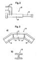
Figur 2 schematisch einen Hydraulikzylinder; - die
Figuren 3a und 3b ein Mitteltunnelwiderlager in einer Seitenansicht und einer Schnittansicht; -
Figur 4 eine schematische Draufsicht auf ein Kraftfahrzeug, bei dem das Armaturendruckplattenset eingesetzt wird; und -
Figur 5 eine schematische Seitenansicht des Kraftfahrzeugs, bei dem das Armaturendruckplattenset eingesetzt wird. - Nachfolgend wird ein Armaturendruckplattenset beschrieben, das bei der in den Figuren gezeigten Ausführungsform zwei Komponenten aufweist, nämlich eine Armaturendruckplatte 10 und ein Mitteltunnelwiderlager 30.
- Die Armaturendruckplatte ist bei der gezeigten Ausführungsform aus einem Doppel-T-Träger gebildet, bei dem zwei Flansche 12, die auf einer Seite eines Mittelgurtes 14 liegen, mit mehreren groben Zähnen 16 versehen sind. Auf der entgegengesetzten Seite des Mittelgurts 14 sind mehrere Querstege 18 angeordnet, so daß voneinander getrennte Teilbereiche 19 gebildet sind, die jeweils eine Abstützfläche bilden. An einer Stirnseite des Mittelgurts 14 ist ein Handgriff 15 angesetzt.
- Das Mitteltunnelwiderlager 30 ist ebenfalls aus einem Doppel-T-Träger hergestellt und weist einen Mittelabschnitt 32 auf, an den zwei sich schräg erstreckende Endabschnitte 34 angesetzt sind. Im Bereich des Übergans vom Mittelabschnitt zum Endabschnitt sind Stege 36 angeordnet, so daß eine Abstützfläche 37 für den Rettungszylinder abgegrenzt ist.
- Die Armaturendruckplatte 10 und das Mitteltunnelwiderlager 30 werden zusammen mit einem Hydraulikzylinder 20 (siehe
Figur 2 ) verwendet, der ein herkömmlicher Rettungszylinder ist. Er weist einen Kolben 22 auf, der beim Zuführen von Hydrauliköl über Leitungen 24 aus einem Zylinder 26 herausgedrückt werden kann. - In den
Figuren 4 und 5 ist schematisch das Armaturendruckplattenset im Einsatz in einem Kraftfahrzeug gezeigt. Es wird hier dazu verwendet, ein Armaturenbrett 40 von einer Rücksitzbank 42 weg nach vorne zu drücken. Auf diese Weise wird der Fahrgastinnenraum im Bereich der Vordersitze 44 wieder auf seine ursprünglichen Abmessungen gebracht. Falls gewünscht, kann das Armaturenbrett auch über seine ursprüngliche Position hinaus nach vorne verschoben werden, so daß den Rettungskräften mehr Bewegungsfreiheit zur Verfügung steht. - Es ist zu sehen, daß die Armaturendruckplatte 10 mittig am Armaturenbrett angesetzt ist. Dabei graben sich die Zähne 16 in das Armaturenbrett ein, so daß ein Abrutschen der Armaturendruckplatte 10 zuverlässig verhindert ist. Die am Armaturenbrett anliegenden Teile der Armaturendruckplatte 10 bilden eine Druckfläche.
- Der Hydraulikzylinder 20 greift mit seinem Kolben 22 in einen der Teilbereiche 19 ein und stützt sich an einem entsprechenden Quersteg 18 ab. Dies verhindert zuverlässig, daß der Hydraulikzylinder 20 von der Armaturendruckplatte 10 abrutscht. Am entgegengesetzten Ende stützt sich der Hydraulikzylinder 20 am Mitteltunnelwiderlager 30 ab, der auf den Mitteltunnel 45 aufgelegt ist und sich an der Rücksitzbank 42 abstützt. Bei den meisten Kraftfahrzeugen ist die Unterkonstruktion der Rücksitzbank fest mit der Karosseriestruktur verbunden, beispielsweise durch ein Knotenblech, so daß hier genügend Widerstand für das Mitteltunnelwiderlager 30 gegeben ist.
- Wie insbesondere in
Figur 4 zu sehen ist, bleibt beim Einsatz des erfindungsgemäßen Armaturendruckplattensets der Zugang zu den Vordersitzen 44 zwischen der A-Säule 46 und der B-Säule 48 frei.
Claims (5)
- Armaturenbrett-Druckplatte (10) mit einer Druckplatte, die mit einer Abstützfläche (19) für einen Hydraulikzylinder (20) auf einer Seite und einer Druckfläche an der entgegengesetzten Seite versehen ist, die dafür vorgesehen ist, an einem Armaturenbrett eines Kraftfahrzeugs angesetzt zu werden, wobei die Druckfläche mit einer Verzahnung (16) versehen ist, die sich in ein Armaturenbrett eingraben kann, wobei die Verzahnung gebildet ist durch zwei Reihen von groben Zähnen (16), die entlang den Außenrändern der Armaturenbrett-Druckplatte (10) angeordnet sind, wobei die Armaturenbrett-Druckplatte aus einem Doppel-T-Träger gebildet ist und die Zähne (16) an zwei Flanschen (12) des Doppel-T-Trägers angeordnet sind, und wobei mehrere Abstützflächen (19) vorgesehen sind, die durch quer verlaufende Stege (18) voneinander getrennt sind, die auf einem Mittelgurt (14) des Doppel-T-Trägers angeordnet sind.
- Armaturenbrett-Druckplatte nach Anspruch 1, dadurch gekennzeichnet, dass die Armaturenbrett-Druckplatte (10) einen Handgriff (15) aufweist.
- Armaturenbrett-Druckplatte nach Anspruch 2, dadurch gekennzeichnet, dass der Handgriff (15) an einer Stirnseite eines Mittelgurts (14) des Doppel-T-Trägers angeordnet ist.
- Armaturenbrett-Druckplattenset mit einer Armaturenbrett-Druckplatte (10) nach einem der vorhergehenden Ansprüche und einem Mitteltunnelwiderlager (30).
- Armaturenbrett-Druckplattenset nach Anspruch 4, dadurch gekennzeichnet, dass das Mitteltunnelwiderlager (30) eine Abstützfläche (37) für ein Ende eines Hydraulikzylinders (20) aufweist, die durch quer verlaufende Stege (36) abgegrenzt ist.
Applications Claiming Priority (2)
| Application Number | Priority Date | Filing Date | Title |
|---|---|---|---|
| DE202007016946U DE202007016946U1 (de) | 2007-12-05 | 2007-12-05 | Armaturendruckplattenset sowie Armaturendruckplatte |
| PCT/EP2008/010304 WO2009071302A1 (de) | 2007-12-05 | 2008-12-04 | Armaturendruckplattenset sowie armaturendruckplatte |
Publications (2)
| Publication Number | Publication Date |
|---|---|
| EP2217330A1 EP2217330A1 (de) | 2010-08-18 |
| EP2217330B1 true EP2217330B1 (de) | 2012-03-21 |
Family
ID=39134987
Family Applications (1)
| Application Number | Title | Priority Date | Filing Date |
|---|---|---|---|
| EP08857274A Not-in-force EP2217330B1 (de) | 2007-12-05 | 2008-12-04 | Armaturendruckplattenset sowie armaturendruckplatte |
Country Status (5)
| Country | Link |
|---|---|
| EP (1) | EP2217330B1 (de) |
| AT (1) | ATE550077T1 (de) |
| DE (1) | DE202007016946U1 (de) |
| ES (1) | ES2383722T3 (de) |
| WO (1) | WO2009071302A1 (de) |
Cited By (1)
| Publication number | Priority date | Publication date | Assignee | Title |
|---|---|---|---|---|
| WO2021216483A1 (en) * | 2020-04-20 | 2021-10-28 | Johnson Jeffery L | Attachment for hydraulic ram rescue tool |
Families Citing this family (3)
| Publication number | Priority date | Publication date | Assignee | Title |
|---|---|---|---|---|
| DE102018119707A1 (de) * | 2018-08-14 | 2020-02-20 | Sebastian Bosel | Druckplatte für einen Rettungsspreizer |
| AT522899A1 (de) * | 2019-09-06 | 2021-03-15 | Weber Hydraulik Gmbh | Rettungseinsatz-Lastverteilungselement zur Abstützung von druckerzeugenden Rettungsgeräten |
| US12180993B2 (en) * | 2022-01-05 | 2024-12-31 | Jeffery L. Johnson | Joint for connecting an attachment to a hydraulic ram |
Family Cites Families (5)
| Publication number | Priority date | Publication date | Assignee | Title |
|---|---|---|---|---|
| US5267462A (en) * | 1992-10-02 | 1993-12-07 | Pijanowski Joseph A | Portable rescue device |
| US6272900B1 (en) * | 1999-04-21 | 2001-08-14 | Matthew Kobel | Extension ram tip |
| US6431522B1 (en) * | 1999-06-02 | 2002-08-13 | Edward G. Cutrell, Sr. | Clamping base for hydraulic spreader |
| US6722176B2 (en) * | 2002-04-18 | 2004-04-20 | Jason Cerrano | Methods and apparatus for performing emergency extrications |
| US6866249B1 (en) * | 2002-12-23 | 2005-03-15 | Shane Campbell | B-post extension device |
-
2007
- 2007-12-05 DE DE202007016946U patent/DE202007016946U1/de not_active Expired - Lifetime
-
2008
- 2008-12-04 ES ES08857274T patent/ES2383722T3/es active Active
- 2008-12-04 EP EP08857274A patent/EP2217330B1/de not_active Not-in-force
- 2008-12-04 AT AT08857274T patent/ATE550077T1/de active
- 2008-12-04 WO PCT/EP2008/010304 patent/WO2009071302A1/de not_active Ceased
Cited By (2)
| Publication number | Priority date | Publication date | Assignee | Title |
|---|---|---|---|---|
| WO2021216483A1 (en) * | 2020-04-20 | 2021-10-28 | Johnson Jeffery L | Attachment for hydraulic ram rescue tool |
| US12251585B2 (en) | 2020-04-20 | 2025-03-18 | Jeffery L. Johnson | Attachment for hydraulic ram rescue tool |
Also Published As
| Publication number | Publication date |
|---|---|
| WO2009071302A1 (de) | 2009-06-11 |
| DE202007016946U1 (de) | 2008-02-28 |
| ATE550077T1 (de) | 2012-04-15 |
| ES2383722T3 (es) | 2012-06-25 |
| EP2217330A1 (de) | 2010-08-18 |
Similar Documents
| Publication | Publication Date | Title |
|---|---|---|
| EP3188928B1 (de) | Deformationselement für einen kraftfahrzeugsitz | |
| EP1310698B1 (de) | Deformationselement, insbesondere für Kraftfahrzeuge | |
| DE10358023B4 (de) | Vorrichtung für ein Kraftfahrzeug zum Insassenschutz bei einem kollisionsbedingten, auf eine Kraftfahrzeugtür gerichteten Energieeintrag | |
| DE102010040021A1 (de) | Türinnenverkleidung für Fahrzeugtüren | |
| DE4424191B4 (de) | Abdeckung, insbesondere Modul- oder Bausteinabdeckung, für eine Luft- oder Gassackeinrichtung | |
| WO2009071302A1 (de) | Armaturendruckplattenset sowie armaturendruckplatte | |
| DE112008001976T5 (de) | Einheit zum Absorbieren von Energie mit zwei Absorptionsvorrichtungen | |
| DE19942973B4 (de) | Fahrzeugsitz mit Crashenergieabsorption | |
| EP3670254B1 (de) | Fahrzeugsitz mit verstellfunktion | |
| WO2015078957A1 (de) | Gassackabdeckung und verfahren zu ihrer herstellung | |
| DE102009057833A1 (de) | Vorrichtung zur Halterung eines Funktionsteils, insbesondere eines Dachhaltegriffs, in einem Fahrzeug | |
| DE102014108340A1 (de) | Stabilisierungseinrichtung bei technischer Hilfeleistung für zu sichernde Objekte | |
| DE102008000936A1 (de) | Radaufhängung für ein Fahrzeug und Verbindungselement für eine solche Radaufhängung | |
| EP1591317B1 (de) | Staufachabdeckung | |
| DE102014012466A1 (de) | Schließkeilsystem als Fahrzeugklappenschloss | |
| EP1608537B1 (de) | Stossabsorbierendes verkleidungsteil für den innenraum von kraftfahrzeugen | |
| DE10214862B4 (de) | Hardtop für ein Cabriolet-Fahrzeug | |
| DE10260792B4 (de) | Vorrichtung zur gegenseitigen Zentrierung zweier Bauteile eines versenkbaren Verdecks für ein Cabriolet-Fahrzeug | |
| DE69204035T2 (de) | Gezackter Schlüssel, insbesondere für Schloss oder Kraftfahrzeug-Diebstahlsicherung. | |
| DE102004027738B4 (de) | Gelenkvorrichtung | |
| WO2003013926A1 (de) | Gegen crash gesicherter unterdruckbremskraftverstärker für kraftfahrzeuge | |
| DE102020102612A1 (de) | Türbaugruppe für ein Kraftfahrzeug | |
| DE102006008222A1 (de) | Kraftfahrzeug mit einer Vorrichtung zur Abdeckung eines Kofferraums | |
| DE102014001088B3 (de) | Fahrzeugkarosserie mit einem Radhaus | |
| DE102004002820A1 (de) | Fahrzeugkarosserieteil mit Zustandsänderung für Fußgängerschutz |
Legal Events
| Date | Code | Title | Description |
|---|---|---|---|
| PUAI | Public reference made under article 153(3) epc to a published international application that has entered the european phase |
Free format text: ORIGINAL CODE: 0009012 |
|
| 17P | Request for examination filed |
Effective date: 20100625 |
|
| AK | Designated contracting states |
Kind code of ref document: A1 Designated state(s): AT BE BG CH CY CZ DE DK EE ES FI FR GB GR HR HU IE IS IT LI LT LU LV MC MT NL NO PL PT RO SE SI SK TR |
|
| AX | Request for extension of the european patent |
Extension state: AL BA MK RS |
|
| RIN1 | Information on inventor provided before grant (corrected) |
Inventor name: ZINDLER, ROBERT |
|
| 17Q | First examination report despatched |
Effective date: 20101217 |
|
| DAX | Request for extension of the european patent (deleted) | ||
| GRAP | Despatch of communication of intention to grant a patent |
Free format text: ORIGINAL CODE: EPIDOSNIGR1 |
|
| GRAS | Grant fee paid |
Free format text: ORIGINAL CODE: EPIDOSNIGR3 |
|
| GRAA | (expected) grant |
Free format text: ORIGINAL CODE: 0009210 |
|
| AK | Designated contracting states |
Kind code of ref document: B1 Designated state(s): AT BE BG CH CY CZ DE DK EE ES FI FR GB GR HR HU IE IS IT LI LT LU LV MC MT NL NO PL PT RO SE SI SK TR |
|
| REG | Reference to a national code |
Ref country code: GB Ref legal event code: FG4D Free format text: NOT ENGLISH |
|
| REG | Reference to a national code |
Ref country code: CH Ref legal event code: EP |
|
| REG | Reference to a national code |
Ref country code: IE Ref legal event code: FG4D Free format text: LANGUAGE OF EP DOCUMENT: GERMAN |
|
| REG | Reference to a national code |
Ref country code: AT Ref legal event code: REF Ref document number: 550077 Country of ref document: AT Kind code of ref document: T Effective date: 20120415 |
|
| REG | Reference to a national code |
Ref country code: CH Ref legal event code: NV Representative=s name: BUGNION S.A. |
|
| REG | Reference to a national code |
Ref country code: DE Ref legal event code: R096 Ref document number: 502008006760 Country of ref document: DE Effective date: 20120516 |
|
| REG | Reference to a national code |
Ref country code: ES Ref legal event code: FG2A Ref document number: 2383722 Country of ref document: ES Kind code of ref document: T3 Effective date: 20120625 |
|
| REG | Reference to a national code |
Ref country code: NL Ref legal event code: T3 |
|
| PG25 | Lapsed in a contracting state [announced via postgrant information from national office to epo] |
Ref country code: NO Free format text: LAPSE BECAUSE OF FAILURE TO SUBMIT A TRANSLATION OF THE DESCRIPTION OR TO PAY THE FEE WITHIN THE PRESCRIBED TIME-LIMIT Effective date: 20120621 Ref country code: HR Free format text: LAPSE BECAUSE OF FAILURE TO SUBMIT A TRANSLATION OF THE DESCRIPTION OR TO PAY THE FEE WITHIN THE PRESCRIBED TIME-LIMIT Effective date: 20120321 Ref country code: LT Free format text: LAPSE BECAUSE OF FAILURE TO SUBMIT A TRANSLATION OF THE DESCRIPTION OR TO PAY THE FEE WITHIN THE PRESCRIBED TIME-LIMIT Effective date: 20120321 |
|
| LTIE | Lt: invalidation of european patent or patent extension |
Effective date: 20120321 |
|
| PG25 | Lapsed in a contracting state [announced via postgrant information from national office to epo] |
Ref country code: LV Free format text: LAPSE BECAUSE OF FAILURE TO SUBMIT A TRANSLATION OF THE DESCRIPTION OR TO PAY THE FEE WITHIN THE PRESCRIBED TIME-LIMIT Effective date: 20120321 Ref country code: GR Free format text: LAPSE BECAUSE OF FAILURE TO SUBMIT A TRANSLATION OF THE DESCRIPTION OR TO PAY THE FEE WITHIN THE PRESCRIBED TIME-LIMIT Effective date: 20120622 Ref country code: FI Free format text: LAPSE BECAUSE OF FAILURE TO SUBMIT A TRANSLATION OF THE DESCRIPTION OR TO PAY THE FEE WITHIN THE PRESCRIBED TIME-LIMIT Effective date: 20120321 |
|
| PG25 | Lapsed in a contracting state [announced via postgrant information from national office to epo] |
Ref country code: CY Free format text: LAPSE BECAUSE OF FAILURE TO SUBMIT A TRANSLATION OF THE DESCRIPTION OR TO PAY THE FEE WITHIN THE PRESCRIBED TIME-LIMIT Effective date: 20120321 |
|
| PG25 | Lapsed in a contracting state [announced via postgrant information from national office to epo] |
Ref country code: SI Free format text: LAPSE BECAUSE OF FAILURE TO SUBMIT A TRANSLATION OF THE DESCRIPTION OR TO PAY THE FEE WITHIN THE PRESCRIBED TIME-LIMIT Effective date: 20120321 Ref country code: EE Free format text: LAPSE BECAUSE OF FAILURE TO SUBMIT A TRANSLATION OF THE DESCRIPTION OR TO PAY THE FEE WITHIN THE PRESCRIBED TIME-LIMIT Effective date: 20120321 Ref country code: IS Free format text: LAPSE BECAUSE OF FAILURE TO SUBMIT A TRANSLATION OF THE DESCRIPTION OR TO PAY THE FEE WITHIN THE PRESCRIBED TIME-LIMIT Effective date: 20120721 Ref country code: PL Free format text: LAPSE BECAUSE OF FAILURE TO SUBMIT A TRANSLATION OF THE DESCRIPTION OR TO PAY THE FEE WITHIN THE PRESCRIBED TIME-LIMIT Effective date: 20120321 Ref country code: SE Free format text: LAPSE BECAUSE OF FAILURE TO SUBMIT A TRANSLATION OF THE DESCRIPTION OR TO PAY THE FEE WITHIN THE PRESCRIBED TIME-LIMIT Effective date: 20120321 Ref country code: CZ Free format text: LAPSE BECAUSE OF FAILURE TO SUBMIT A TRANSLATION OF THE DESCRIPTION OR TO PAY THE FEE WITHIN THE PRESCRIBED TIME-LIMIT Effective date: 20120321 Ref country code: RO Free format text: LAPSE BECAUSE OF FAILURE TO SUBMIT A TRANSLATION OF THE DESCRIPTION OR TO PAY THE FEE WITHIN THE PRESCRIBED TIME-LIMIT Effective date: 20120321 |
|
| PG25 | Lapsed in a contracting state [announced via postgrant information from national office to epo] |
Ref country code: PT Free format text: LAPSE BECAUSE OF FAILURE TO SUBMIT A TRANSLATION OF THE DESCRIPTION OR TO PAY THE FEE WITHIN THE PRESCRIBED TIME-LIMIT Effective date: 20120723 Ref country code: SK Free format text: LAPSE BECAUSE OF FAILURE TO SUBMIT A TRANSLATION OF THE DESCRIPTION OR TO PAY THE FEE WITHIN THE PRESCRIBED TIME-LIMIT Effective date: 20120321 |
|
| PLBE | No opposition filed within time limit |
Free format text: ORIGINAL CODE: 0009261 |
|
| STAA | Information on the status of an ep patent application or granted ep patent |
Free format text: STATUS: NO OPPOSITION FILED WITHIN TIME LIMIT |
|
| PG25 | Lapsed in a contracting state [announced via postgrant information from national office to epo] |
Ref country code: DK Free format text: LAPSE BECAUSE OF FAILURE TO SUBMIT A TRANSLATION OF THE DESCRIPTION OR TO PAY THE FEE WITHIN THE PRESCRIBED TIME-LIMIT Effective date: 20120321 |
|
| 26N | No opposition filed |
Effective date: 20130102 |
|
| REG | Reference to a national code |
Ref country code: DE Ref legal event code: R097 Ref document number: 502008006760 Country of ref document: DE Effective date: 20130102 |
|
| PG25 | Lapsed in a contracting state [announced via postgrant information from national office to epo] |
Ref country code: MC Free format text: LAPSE BECAUSE OF NON-PAYMENT OF DUE FEES Effective date: 20121231 Ref country code: BG Free format text: LAPSE BECAUSE OF FAILURE TO SUBMIT A TRANSLATION OF THE DESCRIPTION OR TO PAY THE FEE WITHIN THE PRESCRIBED TIME-LIMIT Effective date: 20120621 |
|
| REG | Reference to a national code |
Ref country code: IE Ref legal event code: MM4A |
|
| PG25 | Lapsed in a contracting state [announced via postgrant information from national office to epo] |
Ref country code: IE Free format text: LAPSE BECAUSE OF NON-PAYMENT OF DUE FEES Effective date: 20121204 |
|
| PG25 | Lapsed in a contracting state [announced via postgrant information from national office to epo] |
Ref country code: MT Free format text: LAPSE BECAUSE OF FAILURE TO SUBMIT A TRANSLATION OF THE DESCRIPTION OR TO PAY THE FEE WITHIN THE PRESCRIBED TIME-LIMIT Effective date: 20120321 |
|
| PG25 | Lapsed in a contracting state [announced via postgrant information from national office to epo] |
Ref country code: TR Free format text: LAPSE BECAUSE OF FAILURE TO SUBMIT A TRANSLATION OF THE DESCRIPTION OR TO PAY THE FEE WITHIN THE PRESCRIBED TIME-LIMIT Effective date: 20120321 |
|
| PG25 | Lapsed in a contracting state [announced via postgrant information from national office to epo] |
Ref country code: LU Free format text: LAPSE BECAUSE OF NON-PAYMENT OF DUE FEES Effective date: 20121204 |
|
| PG25 | Lapsed in a contracting state [announced via postgrant information from national office to epo] |
Ref country code: HU Free format text: LAPSE BECAUSE OF FAILURE TO SUBMIT A TRANSLATION OF THE DESCRIPTION OR TO PAY THE FEE WITHIN THE PRESCRIBED TIME-LIMIT Effective date: 20081204 |
|
| REG | Reference to a national code |
Ref country code: FR Ref legal event code: PLFP Year of fee payment: 8 |
|
| REG | Reference to a national code |
Ref country code: FR Ref legal event code: PLFP Year of fee payment: 9 |
|
| REG | Reference to a national code |
Ref country code: FR Ref legal event code: PLFP Year of fee payment: 10 |
|
| PGFP | Annual fee paid to national office [announced via postgrant information from national office to epo] |
Ref country code: CH Payment date: 20201221 Year of fee payment: 13 Ref country code: GB Payment date: 20201223 Year of fee payment: 13 Ref country code: FR Payment date: 20201223 Year of fee payment: 13 Ref country code: AT Payment date: 20201222 Year of fee payment: 13 |
|
| PGFP | Annual fee paid to national office [announced via postgrant information from national office to epo] |
Ref country code: BE Payment date: 20201221 Year of fee payment: 13 |
|
| PGFP | Annual fee paid to national office [announced via postgrant information from national office to epo] |
Ref country code: NL Payment date: 20201221 Year of fee payment: 13 |
|
| PGFP | Annual fee paid to national office [announced via postgrant information from national office to epo] |
Ref country code: IT Payment date: 20201224 Year of fee payment: 13 |
|
| PGFP | Annual fee paid to national office [announced via postgrant information from national office to epo] |
Ref country code: ES Payment date: 20210223 Year of fee payment: 13 |
|
| PGFP | Annual fee paid to national office [announced via postgrant information from national office to epo] |
Ref country code: DE Payment date: 20211230 Year of fee payment: 14 |
|
| REG | Reference to a national code |
Ref country code: CH Ref legal event code: PL |
|
| REG | Reference to a national code |
Ref country code: NL Ref legal event code: MM Effective date: 20220101 |
|
| REG | Reference to a national code |
Ref country code: AT Ref legal event code: MM01 Ref document number: 550077 Country of ref document: AT Kind code of ref document: T Effective date: 20211204 |
|
| GBPC | Gb: european patent ceased through non-payment of renewal fee |
Effective date: 20211204 |
|
| REG | Reference to a national code |
Ref country code: BE Ref legal event code: MM Effective date: 20211231 |
|
| PG25 | Lapsed in a contracting state [announced via postgrant information from national office to epo] |
Ref country code: NL Free format text: LAPSE BECAUSE OF NON-PAYMENT OF DUE FEES Effective date: 20220101 |
|
| PG25 | Lapsed in a contracting state [announced via postgrant information from national office to epo] |
Ref country code: GB Free format text: LAPSE BECAUSE OF NON-PAYMENT OF DUE FEES Effective date: 20211204 Ref country code: AT Free format text: LAPSE BECAUSE OF NON-PAYMENT OF DUE FEES Effective date: 20211204 |
|
| PG25 | Lapsed in a contracting state [announced via postgrant information from national office to epo] |
Ref country code: FR Free format text: LAPSE BECAUSE OF NON-PAYMENT OF DUE FEES Effective date: 20211231 Ref country code: BE Free format text: LAPSE BECAUSE OF NON-PAYMENT OF DUE FEES Effective date: 20211231 |
|
| PG25 | Lapsed in a contracting state [announced via postgrant information from national office to epo] |
Ref country code: LI Free format text: LAPSE BECAUSE OF NON-PAYMENT OF DUE FEES Effective date: 20211231 Ref country code: CH Free format text: LAPSE BECAUSE OF NON-PAYMENT OF DUE FEES Effective date: 20211231 |
|
| PG25 | Lapsed in a contracting state [announced via postgrant information from national office to epo] |
Ref country code: IT Free format text: LAPSE BECAUSE OF NON-PAYMENT OF DUE FEES Effective date: 20211204 |
|
| REG | Reference to a national code |
Ref country code: ES Ref legal event code: FD2A Effective date: 20230223 |
|
| PG25 | Lapsed in a contracting state [announced via postgrant information from national office to epo] |
Ref country code: ES Free format text: LAPSE BECAUSE OF NON-PAYMENT OF DUE FEES Effective date: 20211205 |
|
| REG | Reference to a national code |
Ref country code: DE Ref legal event code: R119 Ref document number: 502008006760 Country of ref document: DE |
|
| PG25 | Lapsed in a contracting state [announced via postgrant information from national office to epo] |
Ref country code: DE Free format text: LAPSE BECAUSE OF NON-PAYMENT OF DUE FEES Effective date: 20230701 |