EP2216629B1 - Sensorgerät - Google Patents
Sensorgerät Download PDFInfo
- Publication number
- EP2216629B1 EP2216629B1 EP10152210A EP10152210A EP2216629B1 EP 2216629 B1 EP2216629 B1 EP 2216629B1 EP 10152210 A EP10152210 A EP 10152210A EP 10152210 A EP10152210 A EP 10152210A EP 2216629 B1 EP2216629 B1 EP 2216629B1
- Authority
- EP
- European Patent Office
- Prior art keywords
- failure diagnosis
- section
- signal
- circuit section
- detection
- Prior art date
- Legal status (The legal status is an assumption and is not a legal conclusion. Google has not performed a legal analysis and makes no representation as to the accuracy of the status listed.)
- Active
Links
- 238000001514 detection method Methods 0.000 claims description 81
- 238000003745 diagnosis Methods 0.000 claims description 59
- 230000002159 abnormal effect Effects 0.000 claims description 20
- 230000005856 abnormality Effects 0.000 claims description 10
- 230000001133 acceleration Effects 0.000 description 8
- 238000010586 diagram Methods 0.000 description 6
- 230000005540 biological transmission Effects 0.000 description 3
- 230000000694 effects Effects 0.000 description 2
- 230000006866 deterioration Effects 0.000 description 1
- 230000035945 sensitivity Effects 0.000 description 1
Images


Classifications
-
- G—PHYSICS
- G01—MEASURING; TESTING
- G01D—MEASURING NOT SPECIALLY ADAPTED FOR A SPECIFIC VARIABLE; ARRANGEMENTS FOR MEASURING TWO OR MORE VARIABLES NOT COVERED IN A SINGLE OTHER SUBCLASS; TARIFF METERING APPARATUS; MEASURING OR TESTING NOT OTHERWISE PROVIDED FOR
- G01D5/00—Mechanical means for transferring the output of a sensing member; Means for converting the output of a sensing member to another variable where the form or nature of the sensing member does not constrain the means for converting; Transducers not specially adapted for a specific variable
- G01D5/12—Mechanical means for transferring the output of a sensing member; Means for converting the output of a sensing member to another variable where the form or nature of the sensing member does not constrain the means for converting; Transducers not specially adapted for a specific variable using electric or magnetic means
- G01D5/244—Mechanical means for transferring the output of a sensing member; Means for converting the output of a sensing member to another variable where the form or nature of the sensing member does not constrain the means for converting; Transducers not specially adapted for a specific variable using electric or magnetic means influencing characteristics of pulses or pulse trains; generating pulses or pulse trains
- G01D5/24457—Failure detection
- G01D5/24461—Failure detection by redundancy or plausibility
-
- H—ELECTRICITY
- H02—GENERATION; CONVERSION OR DISTRIBUTION OF ELECTRIC POWER
- H02H—EMERGENCY PROTECTIVE CIRCUIT ARRANGEMENTS
- H02H5/00—Emergency protective circuit arrangements for automatic disconnection directly responsive to an undesired change from normal non-electric working conditions with or without subsequent reconnection
-
- G—PHYSICS
- G01—MEASURING; TESTING
- G01D—MEASURING NOT SPECIALLY ADAPTED FOR A SPECIFIC VARIABLE; ARRANGEMENTS FOR MEASURING TWO OR MORE VARIABLES NOT COVERED IN A SINGLE OTHER SUBCLASS; TARIFF METERING APPARATUS; MEASURING OR TESTING NOT OTHERWISE PROVIDED FOR
- G01D18/00—Testing or calibrating apparatus or arrangements provided for in groups G01D1/00 - G01D15/00
-
- G—PHYSICS
- G01—MEASURING; TESTING
- G01D—MEASURING NOT SPECIALLY ADAPTED FOR A SPECIFIC VARIABLE; ARRANGEMENTS FOR MEASURING TWO OR MORE VARIABLES NOT COVERED IN A SINGLE OTHER SUBCLASS; TARIFF METERING APPARATUS; MEASURING OR TESTING NOT OTHERWISE PROVIDED FOR
- G01D5/00—Mechanical means for transferring the output of a sensing member; Means for converting the output of a sensing member to another variable where the form or nature of the sensing member does not constrain the means for converting; Transducers not specially adapted for a specific variable
- G01D5/12—Mechanical means for transferring the output of a sensing member; Means for converting the output of a sensing member to another variable where the form or nature of the sensing member does not constrain the means for converting; Transducers not specially adapted for a specific variable using electric or magnetic means
- G01D5/244—Mechanical means for transferring the output of a sensing member; Means for converting the output of a sensing member to another variable where the form or nature of the sensing member does not constrain the means for converting; Transducers not specially adapted for a specific variable using electric or magnetic means influencing characteristics of pulses or pulse trains; generating pulses or pulse trains
- G01D5/24457—Failure detection
-
- G—PHYSICS
- G01—MEASURING; TESTING
- G01P—MEASURING LINEAR OR ANGULAR SPEED, ACCELERATION, DECELERATION, OR SHOCK; INDICATING PRESENCE, ABSENCE, OR DIRECTION, OF MOVEMENT
- G01P15/00—Measuring acceleration; Measuring deceleration; Measuring shock, i.e. sudden change of acceleration
-
- G—PHYSICS
- G01—MEASURING; TESTING
- G01P—MEASURING LINEAR OR ANGULAR SPEED, ACCELERATION, DECELERATION, OR SHOCK; INDICATING PRESENCE, ABSENCE, OR DIRECTION, OF MOVEMENT
- G01P3/00—Measuring linear or angular speed; Measuring differences of linear or angular speeds
- G01P3/42—Devices characterised by the use of electric or magnetic means
- G01P3/44—Devices characterised by the use of electric or magnetic means for measuring angular speed
Definitions
- the present invention relates to a sensor apparatus for use in automobiles, aircraft, vessels, robots, a variety of other electronic devices, and the like.
- FIG. 3 is an electric circuit diagram showing the conventional sensor apparatus.
- the sensor apparatus includes: first and second drive circuit sections 1A, 1B for outputting drive signals that drive detection device 2; and first and second detection circuit sections 3A, 3B for fetching response signals from detection device 2.
- the sensor apparatus further includes: first and second processing circuit sections 4A, 4B for fetching sensor signals from response signals from first and second detection circuit sections 3A, 3B; and output terminals 5A, 5B for outputting sense signals from first and second processing circuits 4A, 4B.
- At least one of first and second drive circuit sections1A, 1B, detection device 2, first and second detection circuit sections 3A, 3B, and first and second processing circuit sections 4A, 4B is set as an object of failure diagnosis and referred to as a failure diagnosis object section.
- Failure diagnosis circuit 6 electrically connected to the failure diagnosis object section performs failure detection on the failure diagnosis object section, and outputs a failure detection signal from output terminal 8 provided in failure diagnosis circuit 6.
- Patent Document 1 Unexamined Japanese Patent Publication No. 2004-301512
- a sensor apparatus of the present invention includes: a drive circuit section for outputting a drive signal; a detection device, into which a drive signal from the drive circuit section is inputted; a detection circuit section for fetching a response signal from the detection device; a processing circuit section, into which a response signal from the detection circuit section is inputted and which fetches a sense signal from this response signal; a first output terminal for outputting a sense signal from the processing circuit section; a failure diagnosis circuit for setting as a failure diagnosis object section at least any one of a drive circuit section, a detection device, the detection circuit section and the processing circuit section, determining whether the failure diagnosis object section is normal or abnormal, and also outputting a failure detection signal from a second output terminal in the case of determining abnormality; and a delay unit which is provided at any place on an electric connection line from the failure diagnosis object section to the first output terminal.
- the sensor apparatus is configured such that the time required for an output concerning the failure detection signal from the failure diagnosis object section to reach the second output terminal is shorter than the time required
- a failure detection signal indicating the sense signal being one under abnormal condition can be outputted from the second output terminal. This can prevent the sense signal under abnormal condition from being used for control of an automobile or the like, resulting in improvement in reliability.
- Fig. 1 is an electric circuit diagram showing a sensor apparatus of the present invention.
- the sensor apparatus in the present embodiment includes: first and second drive circuit sections 11A, 11B for outputting drive signals; angular velocity detection device 12A, into which a first drive signal from first drive circuit section 11A is inputted; and acceleration detection device 12B, into which a second drive signal from second drive circuit section 11B is inputted.
- the sensor apparatus includes: first detection circuit section 13A for fetching a first response signal from angular velocity detection device 12A; and second detection circuit section 13B for fetching a second response signal from acceleration detection device 12B.
- the sensor apparatus further includes: first processing circuit section 14A; second processing circuit section 14B; and first output terminals 15A, 15B for outputting sense signals from first and second processing circuit sections 14A, 14B.
- First processing circuit section 14A receives an input of the first response signal from first detection circuit section 13A and also fetches a first sense signal from this first response signal.
- Second processing circuit section 14B receives an input of the second response signal from second detection circuit section 13B and also fetches a second sense signal from this second response signal.
- At least one of first drive circuit section 11A, angular velocity detection device 12A, first detection circuit section 13A and first processing circuit section 14A is set as a first failure diagnosis object section.
- At least one of second drive circuit section 11B, acceleration detection circuit 12B, second detection circuit section 13B and second processing circuit section 14B is set as a second failure diagnosis object section.
- Failure diagnosis circuit 16 determines whether first and second failure diagnosis object sections are normal or abnormal, and outputs a failure detection signal indicating abnormality of the sense signal from second output terminal 16A in the case of determining abnormality.
- failure diagnosis circuit 16 is electrically connected to both first detection circuit section 13A and second detection circuit section 13B, and first detection circuit section 13A is set as the first failure diagnosis object section while second detection circuit section 13B is set as the second failure diagnosis object section. Failure diagnosis circuit 16 determines whether each of first and second detection circuit sections 13A, 13B is normal or abnormal.
- T1 The time required for an output concerning each of the failure detection signals to be transmitted from first and second detection circuit sections 13A, 13B as the first and second failure diagnosis object sections to second output terminal 16A through failure diagnosis circuit 16 is referred to as T1
- T2 the time required for an output concerning each of the first and second sense signals, namely the first and second respond signals to reach first output terminals 15A, 15B from first and second detection circuit sections 13A, 13B
- T1 is shorter than time T2
- the failure detection signals are outputted prior to the first and second sense signals.
- failure detection signals can be outputted from second output terminal 16A before the first and second sense signals are outputted from first output terminals 15A, 15B, it is possible to prevent the first and second sense signals under abnormal condition from being erroneously used for control of an automobile or the like, so as to improve the reliability.
- the failure detection signals under abnormal condition may not be outputted in time. It may result in that the first and second sense signals under abnormal condition are used for control of automobile or the like.
- the failure detection signals indicating abnormality of the sense signals can be outputted from second output terminal 16A. It is therefore possible to prevent the first and second sense signals under abnormal condition from being used for control of an automobile or the like, thus leading to improvement in reliability.
- the first and second sense signals and the failure detection signals may be either digital output signals or analog output signals.
- a configuration adopting analog output signals can be realized by separately providing first output terminals 15A, 15B, from which the first and second sense signals are outputted, and second output terminal 16A, from which the failure detection signals are outputted.
- first and second detection circuit sections 13A, 13B are set as the first and second failure diagnosis object sections and the identical portions respectively in the angular velocity detection system and the acceleration detection system are set as the failure diagnosis object sections.
- it may be configured such that non-identical portions respectively in the angular velocity detection system and the acceleration detection system are set as the two failure diagnosis object sections, as in a case where first drive circuit section 11A is set as the first failure diagnosis object section and second processing circuit section 14B is set as the second failure diagnosis object section.
- T2 a shorter one between respective transmission time of outputs concerning first and second sense signals from the first and second failure diagnosis object sections to first output terminals 15A, 15B
- T1 a longer one between respective transmission time of outputs concerning failure detection signals from the first and second failure diagnosis object sections to second output terminal 16A
- time T1 is shorter than time T2.
- the description is given using the two devices, angular velocity detection device 12A and acceleration detection device 12B, as detection device 12 and also using, as the circuit configuration corresponding thereto, the configuration having first and second drive circuit sections 11A, 11B, first and second detection circuit sections 13A, 13B, and first and second processing circuit sections 14A, 14B.
- it may be configured such that one detection device 12 is provided and as a circuit configuration corresponding thereto and only each one drive circuit section, detection circuit section, and processing circuit section is provided.
- detection device 12 is an element of the sensor apparatus in the present embodiment
- the present invention can also be configured even with detection device 12 not being an element of the sensor apparatus.
- the sensor apparatus of the present invention can be configured by including a drive circuit section, a detection circuit section, a processing circuit section, a failure diagnosis circuit, and an output circuit section, which exchange signals with detection device 12 provided outside the sensor apparatus.
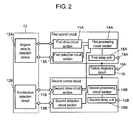
- Fig. 2 is an electric circuit diagram showing another example of the sensor apparatus of the present invention.
- first delay unit 18A is provided at any place on an electric connection line from first drive circuit section 11A to angular velocity detection device 12A, first detection circuit section 13A, first processing circuit section 14A, and to first output terminal 15A.
- Second delay unit 18B is provided at any place on an electric connection line from second drive circuit section 11B to acceleration detection device 12B, second detection circuit section 13B, second processing circuit section 14B, and to first output terminal 15B.
- first and second delay units 18A, 18B provided, it is possible to more certainly obtain an effect concerning the forgoing improvement in reliability, which is desirable.
- first and second delay units 18A, 18B can reliably make time T1 shorter than time T2 required for an output concerning each of the first and second sense signals to reach first output terminals 15A, 15B from the failure diagnosis object sections.
- failure diagnosis circuit 16 determining abnormality of the failure diagnosis object section, a signal outside a range of a normal output voltage is outputted from each of first output terminals 15A, 15B.
- failure diagnosis circuit 16 determines abnormality of the failure diagnosis object sections
- failure diagnosis circuit 16 transmits that information to first and second processing circuit sections 14A, 14B, and first and second processing circuit sections 14A, 14B output values to be outputted from first output terminals 15A, 15B as values outside the range of the normal output voltage.
- the information transmitted by failure diagnosis circuit 16 to each of first and second processing circuit sections 14A, 14B is hereinafter referred to as an "abnormal voltage value output order signal".
- normal output voltage range means a range of ⁇ 1.8V from a 0-point voltage when sensitivity is 6 mV/deg/s and a dynamic range is ⁇ 300 deg/s.
- the normal output voltage range is from 1.55 to 4.45 V.
- the time required for transmission of an output concerning the failure detection signal from the failure diagnosis object section to failure diagnosis circuit 16 and outputting of an "abnormal voltage value output order signal" by failure diagnosis circuit 16 is referred to as "T3". It is desirably configured to make time T3 shorter than time T2 required for the output concerning each of the first and second sense signals to reach first output terminals 15A, 15B from the first and second failure diagnosis object sections. With such a configuration, it is possible to more certainly output a sense signal under abnormal condition as a value "outside the range of the normal output voltage", so as to seek further improvement in reliability.
- the sensor apparatus of the present invention has an effect of allowing improvement in reliability, and is useful in automobiles, aircraft, vessels, robots, a variety of other electronic devices, and the like.
Landscapes
- Physics & Mathematics (AREA)
- General Physics & Mathematics (AREA)
- Testing Or Calibration Of Command Recording Devices (AREA)
- Gyroscopes (AREA)
- Transmission And Conversion Of Sensor Element Output (AREA)
Claims (2)
- Sensorvorrichtung, die umfasst:einen Ansteuerschaltungs-Abschnitt zum Ausgeben eines Ansteuersignals;eine Erfassungseinrichtung, in die das Ansteuersignal von dem Ansteuerschaltungs-Abschnitt eingegeben wird;einen Erfassungsschaltungs-Abschnitt zum Abrufen eines Antwortsignals von der Erfassungseinrichtung;einen Verarbeitungsschaltungs-Abschnitt, in den das Antwortsignal von dem Erfassungsschaltungs-Abschnitt eingegeben wird und der das Mess-Signal aus diesem Antwortsignal abruft;einen ersten Ausgangsanschluss zum Ausgeben eines Mess-Signals aus dem Verarbeitungsschaltungs-Abschnitt; undeine Fehlerdiagnose-Schaltung, mit der wenigstens irgendeiner des Ansteuerschaltungs-Abschnitts, der Erfassungseinrichtung, des Erfassungsschaltungs-Abschnitts oder/und des Verarbeitungsschaltungs-Abschnitts als ein Fehlerdiagnoseobjekt-Abschnitt festgelegt wird/werden, mit der festgestellt wird, ob der Fehlerdiagnoseobjekt-Abschnitt normal oder abnormal ist, und mit der des Weiteren ein Fehlererfassungs-Signal von einem zweiten Ausgangsanschluss ausgegeben wird, wenn Abnormalität festgestellt wird,wobei die Zeit, die erforderlich ist, bis ein Ausgang bezüglich des Fehlererfassungs-Signals von dem Fehlerdiagnoseobjekt-Abschnitt den zweiten Ausgangsanschluss erreicht, kürzer ist als die Zeit, die erforderlich ist, bis ein Ausgang bezüglich des Mess-Signals von dem Fehlerdiagnoseobjekt-Abschnitt den ersten Ausgangsanschluss erreicht,und eine Verzögerungseinheit an jeder beliebigen Stelle auf einer elektrischen Verbindungsleitung von dem Fehlerdiagnoseobjekt-Abschnitt zu dem ersten Ausgangsanschluss vorhanden ist.
- Sensorvorrichtung nach Anspruch 1, wobei, wenn Abnormalität des Fehlerdiagnoseobjekt-Abschnitts festgestellt wird, die Fehlerdiagnose-Schaltung ein Befehls-Signal zum Ausgeben eines abnormalen Spannungswertes ausgibt und der erste Ausgangsanschluss ein Signal außerhalb eines Bereiches einer normalen Ausgangsspannung ausgibt.
Applications Claiming Priority (1)
| Application Number | Priority Date | Filing Date | Title |
|---|---|---|---|
| JP2009024663A JP4337952B1 (ja) | 2009-02-05 | 2009-02-05 | センサ装置 |
Publications (2)
| Publication Number | Publication Date |
|---|---|
| EP2216629A1 EP2216629A1 (de) | 2010-08-11 |
| EP2216629B1 true EP2216629B1 (de) | 2013-01-09 |
Family
ID=41190710
Family Applications (1)
| Application Number | Title | Priority Date | Filing Date |
|---|---|---|---|
| EP10152210A Active EP2216629B1 (de) | 2009-02-05 | 2010-02-01 | Sensorgerät |
Country Status (5)
| Country | Link |
|---|---|
| US (2) | US8055404B2 (de) |
| EP (1) | EP2216629B1 (de) |
| JP (1) | JP4337952B1 (de) |
| KR (1) | KR100972077B1 (de) |
| CN (1) | CN101799481B (de) |
Families Citing this family (8)
| Publication number | Priority date | Publication date | Assignee | Title |
|---|---|---|---|---|
| US8322214B2 (en) | 2008-04-04 | 2012-12-04 | Panasonic Corporation | Sensor device |
| US8131508B2 (en) | 2009-02-05 | 2012-03-06 | Panasonic Corporation | Sensor apparatus |
| JP5685842B2 (ja) | 2010-07-12 | 2015-03-18 | セイコーエプソン株式会社 | ロボット装置およびロボット装置の制御方法 |
| EP2636997A1 (de) * | 2012-03-05 | 2013-09-11 | SICK STEGMANN GmbH | Positionsgeber |
| US10118592B2 (en) * | 2015-08-04 | 2018-11-06 | Ford Global Technologies, Llc | Diagnostic port protection to body control module |
| CN106713572B (zh) * | 2016-12-27 | 2019-12-06 | Oppo广东移动通信有限公司 | 一种数据上报的控制方法、装置及终端 |
| CN109115247B (zh) * | 2017-06-26 | 2021-03-02 | 大陆汽车电子(连云港)有限公司 | 用于监控传感器与连接器之间的连接的系统和方法 |
| JP2023183810A (ja) * | 2022-06-16 | 2023-12-28 | ニデックインスツルメンツ株式会社 | エンコーダ配線の障害検出装置 |
Family Cites Families (19)
| Publication number | Priority date | Publication date | Assignee | Title |
|---|---|---|---|---|
| JPS5636093B2 (de) * | 1973-03-16 | 1981-08-21 | ||
| JP3447860B2 (ja) * | 1995-09-18 | 2003-09-16 | 株式会社ミクニ | 故障判定機能を有する磁気式位置センサ |
| JP2001074503A (ja) * | 1999-09-07 | 2001-03-23 | Hitachi Ltd | エンコーダ及びモータ駆動装置 |
| JP2004264074A (ja) * | 2003-02-28 | 2004-09-24 | Showa Denshi Kogyo Kk | 環境変化監視システムと環境変化検出装置及び監視装置 |
| JP2004301512A (ja) | 2003-03-28 | 2004-10-28 | Denso Corp | 角速度センサ装置 |
| JP2005283481A (ja) * | 2004-03-30 | 2005-10-13 | Denso Corp | センサシステム |
| JP2005331332A (ja) * | 2004-05-19 | 2005-12-02 | Denso Corp | センサ装置 |
| JP4056532B2 (ja) | 2005-03-31 | 2008-03-05 | 日本航空電子工業株式会社 | 故障診断機能付きmemsデバイス |
| JP4968069B2 (ja) * | 2005-07-19 | 2012-07-04 | 株式会社安川電機 | 異常検出装置付きエンコーダおよびその制御システム |
| US7730872B2 (en) | 2005-11-30 | 2010-06-08 | Ford Global Technologies, Llc | Engine with water and/or ethanol direct injection plus gas port fuel injectors |
| DE102006012074B4 (de) | 2006-03-16 | 2015-11-05 | Robert Bosch Gmbh | Postionsmesseinrichtung mit Überwachungsvorrichtung |
| JP5147097B2 (ja) | 2006-05-09 | 2013-02-20 | 東京エレクトロン株式会社 | サーバ装置、およびプログラム |
| DE102006023213B3 (de) * | 2006-05-17 | 2007-09-27 | Siemens Ag | Betriebsverfahren für einen Geber und eine mit dem Geber kommunizierende Steuereinrichtung |
| JP2008002890A (ja) * | 2006-06-21 | 2008-01-10 | Yokogawa Electric Corp | 計測装置管理システム |
| US7730782B2 (en) | 2008-04-04 | 2010-06-08 | Panasonic Corporation | Sensor device |
| US8322214B2 (en) | 2008-04-04 | 2012-12-04 | Panasonic Corporation | Sensor device |
| JP4245081B1 (ja) * | 2008-10-16 | 2009-03-25 | パナソニック株式会社 | センサ装置 |
| JP4386143B1 (ja) | 2009-02-05 | 2009-12-16 | パナソニック株式会社 | センサ装置 |
| US8131508B2 (en) | 2009-02-05 | 2012-03-06 | Panasonic Corporation | Sensor apparatus |
-
2009
- 2009-02-05 JP JP2009024663A patent/JP4337952B1/ja active Active
-
2010
- 2010-01-22 KR KR1020100005950A patent/KR100972077B1/ko not_active Expired - Fee Related
- 2010-01-26 US US12/693,757 patent/US8055404B2/en active Active
- 2010-01-28 CN CN2010101056769A patent/CN101799481B/zh active Active
- 2010-02-01 EP EP10152210A patent/EP2216629B1/de active Active
-
2011
- 2011-05-02 US US13/098,813 patent/US8103400B2/en active Active
Also Published As
| Publication number | Publication date |
|---|---|
| CN101799481B (zh) | 2012-07-04 |
| US8103400B2 (en) | 2012-01-24 |
| JP2010181259A (ja) | 2010-08-19 |
| CN101799481A (zh) | 2010-08-11 |
| US8055404B2 (en) | 2011-11-08 |
| KR100972077B1 (ko) | 2010-07-22 |
| JP4337952B1 (ja) | 2009-09-30 |
| EP2216629A1 (de) | 2010-08-11 |
| US20110208443A1 (en) | 2011-08-25 |
| US20100194401A1 (en) | 2010-08-05 |
Similar Documents
| Publication | Publication Date | Title |
|---|---|---|
| EP2216629B1 (de) | Sensorgerät | |
| US7746091B2 (en) | Sensor apparatus | |
| US8131507B2 (en) | Sensor apparatus | |
| US7775109B2 (en) | Sensor device | |
| US8131508B2 (en) | Sensor apparatus | |
| US10946892B2 (en) | Electric power steering apparatus having increased number of sensor signals for safety enhancement | |
| JP4358301B1 (ja) | センサ装置 | |
| JP4311496B1 (ja) | 慣性センサ | |
| KR20190028842A (ko) | 페일-세이프 전동식 파워 스티어링 장치 및 방법 | |
| US8322214B2 (en) | Sensor device | |
| CN114630783B (zh) | 分析装置和机动车转向装置 | |
| JP2010096602A (ja) | センサ装置 | |
| WO2009122739A1 (ja) | センサ装置 |
Legal Events
| Date | Code | Title | Description |
|---|---|---|---|
| PUAI | Public reference made under article 153(3) epc to a published international application that has entered the european phase |
Free format text: ORIGINAL CODE: 0009012 |
|
| 17P | Request for examination filed |
Effective date: 20100201 |
|
| AK | Designated contracting states |
Kind code of ref document: A1 Designated state(s): AT BE BG CH CY CZ DE DK EE ES FI FR GB GR HR HU IE IS IT LI LT LU LV MC MK MT NL NO PL PT RO SE SI SK SM TR |
|
| AX | Request for extension of the european patent |
Extension state: AL BA RS |
|
| GRAJ | Information related to disapproval of communication of intention to grant by the applicant or resumption of examination proceedings by the epo deleted |
Free format text: ORIGINAL CODE: EPIDOSDIGR1 |
|
| GRAP | Despatch of communication of intention to grant a patent |
Free format text: ORIGINAL CODE: EPIDOSNIGR1 |
|
| GRAS | Grant fee paid |
Free format text: ORIGINAL CODE: EPIDOSNIGR3 |
|
| GRAA | (expected) grant |
Free format text: ORIGINAL CODE: 0009210 |
|
| AK | Designated contracting states |
Kind code of ref document: B1 Designated state(s): AT BE BG CH CY CZ DE DK EE ES FI FR GB GR HR HU IE IS IT LI LT LU LV MC MK MT NL NO PL PT RO SE SI SK SM TR |
|
| REG | Reference to a national code |
Ref country code: GB Ref legal event code: FG4D |
|
| REG | Reference to a national code |
Ref country code: AT Ref legal event code: REF Ref document number: 593004 Country of ref document: AT Kind code of ref document: T Effective date: 20130115 Ref country code: CH Ref legal event code: EP |
|
| REG | Reference to a national code |
Ref country code: IE Ref legal event code: FG4D |
|
| REG | Reference to a national code |
Ref country code: DE Ref legal event code: R096 Ref document number: 602010004474 Country of ref document: DE Effective date: 20130314 |
|
| PG25 | Lapsed in a contracting state [announced via postgrant information from national office to epo] |
Ref country code: SI Free format text: LAPSE BECAUSE OF FAILURE TO SUBMIT A TRANSLATION OF THE DESCRIPTION OR TO PAY THE FEE WITHIN THE PRESCRIBED TIME-LIMIT Effective date: 20130109 |
|
| REG | Reference to a national code |
Ref country code: NL Ref legal event code: VDEP Effective date: 20130109 |
|
| REG | Reference to a national code |
Ref country code: AT Ref legal event code: MK05 Ref document number: 593004 Country of ref document: AT Kind code of ref document: T Effective date: 20130109 |
|
| REG | Reference to a national code |
Ref country code: LT Ref legal event code: MG4D |
|
| PG25 | Lapsed in a contracting state [announced via postgrant information from national office to epo] |
Ref country code: BG Free format text: LAPSE BECAUSE OF FAILURE TO SUBMIT A TRANSLATION OF THE DESCRIPTION OR TO PAY THE FEE WITHIN THE PRESCRIBED TIME-LIMIT Effective date: 20130409 Ref country code: NO Free format text: LAPSE BECAUSE OF FAILURE TO SUBMIT A TRANSLATION OF THE DESCRIPTION OR TO PAY THE FEE WITHIN THE PRESCRIBED TIME-LIMIT Effective date: 20130409 Ref country code: AT Free format text: LAPSE BECAUSE OF FAILURE TO SUBMIT A TRANSLATION OF THE DESCRIPTION OR TO PAY THE FEE WITHIN THE PRESCRIBED TIME-LIMIT Effective date: 20130109 Ref country code: ES Free format text: LAPSE BECAUSE OF FAILURE TO SUBMIT A TRANSLATION OF THE DESCRIPTION OR TO PAY THE FEE WITHIN THE PRESCRIBED TIME-LIMIT Effective date: 20130420 Ref country code: LT Free format text: LAPSE BECAUSE OF FAILURE TO SUBMIT A TRANSLATION OF THE DESCRIPTION OR TO PAY THE FEE WITHIN THE PRESCRIBED TIME-LIMIT Effective date: 20130109 Ref country code: SE Free format text: LAPSE BECAUSE OF FAILURE TO SUBMIT A TRANSLATION OF THE DESCRIPTION OR TO PAY THE FEE WITHIN THE PRESCRIBED TIME-LIMIT Effective date: 20130109 Ref country code: BE Free format text: LAPSE BECAUSE OF FAILURE TO SUBMIT A TRANSLATION OF THE DESCRIPTION OR TO PAY THE FEE WITHIN THE PRESCRIBED TIME-LIMIT Effective date: 20130109 Ref country code: IS Free format text: LAPSE BECAUSE OF FAILURE TO SUBMIT A TRANSLATION OF THE DESCRIPTION OR TO PAY THE FEE WITHIN THE PRESCRIBED TIME-LIMIT Effective date: 20130509 |
|
| PG25 | Lapsed in a contracting state [announced via postgrant information from national office to epo] |
Ref country code: NL Free format text: LAPSE BECAUSE OF FAILURE TO SUBMIT A TRANSLATION OF THE DESCRIPTION OR TO PAY THE FEE WITHIN THE PRESCRIBED TIME-LIMIT Effective date: 20130109 Ref country code: PL Free format text: LAPSE BECAUSE OF FAILURE TO SUBMIT A TRANSLATION OF THE DESCRIPTION OR TO PAY THE FEE WITHIN THE PRESCRIBED TIME-LIMIT Effective date: 20130109 Ref country code: FI Free format text: LAPSE BECAUSE OF FAILURE TO SUBMIT A TRANSLATION OF THE DESCRIPTION OR TO PAY THE FEE WITHIN THE PRESCRIBED TIME-LIMIT Effective date: 20130109 Ref country code: PT Free format text: LAPSE BECAUSE OF FAILURE TO SUBMIT A TRANSLATION OF THE DESCRIPTION OR TO PAY THE FEE WITHIN THE PRESCRIBED TIME-LIMIT Effective date: 20130509 Ref country code: LV Free format text: LAPSE BECAUSE OF FAILURE TO SUBMIT A TRANSLATION OF THE DESCRIPTION OR TO PAY THE FEE WITHIN THE PRESCRIBED TIME-LIMIT Effective date: 20130109 Ref country code: GR Free format text: LAPSE BECAUSE OF FAILURE TO SUBMIT A TRANSLATION OF THE DESCRIPTION OR TO PAY THE FEE WITHIN THE PRESCRIBED TIME-LIMIT Effective date: 20130410 |
|
| PG25 | Lapsed in a contracting state [announced via postgrant information from national office to epo] |
Ref country code: HR Free format text: LAPSE BECAUSE OF FAILURE TO SUBMIT A TRANSLATION OF THE DESCRIPTION OR TO PAY THE FEE WITHIN THE PRESCRIBED TIME-LIMIT Effective date: 20130109 Ref country code: MC Free format text: LAPSE BECAUSE OF NON-PAYMENT OF DUE FEES Effective date: 20130228 |
|
| PG25 | Lapsed in a contracting state [announced via postgrant information from national office to epo] |
Ref country code: SK Free format text: LAPSE BECAUSE OF FAILURE TO SUBMIT A TRANSLATION OF THE DESCRIPTION OR TO PAY THE FEE WITHIN THE PRESCRIBED TIME-LIMIT Effective date: 20130109 Ref country code: CZ Free format text: LAPSE BECAUSE OF FAILURE TO SUBMIT A TRANSLATION OF THE DESCRIPTION OR TO PAY THE FEE WITHIN THE PRESCRIBED TIME-LIMIT Effective date: 20130109 Ref country code: EE Free format text: LAPSE BECAUSE OF FAILURE TO SUBMIT A TRANSLATION OF THE DESCRIPTION OR TO PAY THE FEE WITHIN THE PRESCRIBED TIME-LIMIT Effective date: 20130109 Ref country code: DK Free format text: LAPSE BECAUSE OF FAILURE TO SUBMIT A TRANSLATION OF THE DESCRIPTION OR TO PAY THE FEE WITHIN THE PRESCRIBED TIME-LIMIT Effective date: 20130109 Ref country code: RO Free format text: LAPSE BECAUSE OF FAILURE TO SUBMIT A TRANSLATION OF THE DESCRIPTION OR TO PAY THE FEE WITHIN THE PRESCRIBED TIME-LIMIT Effective date: 20130109 |
|
| PLBE | No opposition filed within time limit |
Free format text: ORIGINAL CODE: 0009261 |
|
| STAA | Information on the status of an ep patent application or granted ep patent |
Free format text: STATUS: NO OPPOSITION FILED WITHIN TIME LIMIT |
|
| PG25 | Lapsed in a contracting state [announced via postgrant information from national office to epo] |
Ref country code: CY Free format text: LAPSE BECAUSE OF FAILURE TO SUBMIT A TRANSLATION OF THE DESCRIPTION OR TO PAY THE FEE WITHIN THE PRESCRIBED TIME-LIMIT Effective date: 20130109 |
|
| REG | Reference to a national code |
Ref country code: IE Ref legal event code: MM4A |
|
| 26N | No opposition filed |
Effective date: 20131010 |
|
| PG25 | Lapsed in a contracting state [announced via postgrant information from national office to epo] |
Ref country code: IT Free format text: LAPSE BECAUSE OF FAILURE TO SUBMIT A TRANSLATION OF THE DESCRIPTION OR TO PAY THE FEE WITHIN THE PRESCRIBED TIME-LIMIT Effective date: 20130109 |
|
| REG | Reference to a national code |
Ref country code: DE Ref legal event code: R097 Ref document number: 602010004474 Country of ref document: DE Effective date: 20131010 |
|
| PG25 | Lapsed in a contracting state [announced via postgrant information from national office to epo] |
Ref country code: IE Free format text: LAPSE BECAUSE OF NON-PAYMENT OF DUE FEES Effective date: 20130201 |
|
| PGFP | Annual fee paid to national office [announced via postgrant information from national office to epo] |
Ref country code: FR Payment date: 20140219 Year of fee payment: 5 |
|
| PG25 | Lapsed in a contracting state [announced via postgrant information from national office to epo] |
Ref country code: MT Free format text: LAPSE BECAUSE OF FAILURE TO SUBMIT A TRANSLATION OF THE DESCRIPTION OR TO PAY THE FEE WITHIN THE PRESCRIBED TIME-LIMIT Effective date: 20130109 |
|
| PGFP | Annual fee paid to national office [announced via postgrant information from national office to epo] |
Ref country code: GB Payment date: 20140218 Year of fee payment: 5 |
|
| REG | Reference to a national code |
Ref country code: CH Ref legal event code: PL |
|
| PG25 | Lapsed in a contracting state [announced via postgrant information from national office to epo] |
Ref country code: LI Free format text: LAPSE BECAUSE OF NON-PAYMENT OF DUE FEES Effective date: 20140228 Ref country code: CH Free format text: LAPSE BECAUSE OF NON-PAYMENT OF DUE FEES Effective date: 20140228 |
|
| PG25 | Lapsed in a contracting state [announced via postgrant information from national office to epo] |
Ref country code: SM Free format text: LAPSE BECAUSE OF FAILURE TO SUBMIT A TRANSLATION OF THE DESCRIPTION OR TO PAY THE FEE WITHIN THE PRESCRIBED TIME-LIMIT Effective date: 20130109 |
|
| PG25 | Lapsed in a contracting state [announced via postgrant information from national office to epo] |
Ref country code: TR Free format text: LAPSE BECAUSE OF FAILURE TO SUBMIT A TRANSLATION OF THE DESCRIPTION OR TO PAY THE FEE WITHIN THE PRESCRIBED TIME-LIMIT Effective date: 20130109 |
|
| PG25 | Lapsed in a contracting state [announced via postgrant information from national office to epo] |
Ref country code: LU Free format text: LAPSE BECAUSE OF NON-PAYMENT OF DUE FEES Effective date: 20130201 Ref country code: MK Free format text: LAPSE BECAUSE OF FAILURE TO SUBMIT A TRANSLATION OF THE DESCRIPTION OR TO PAY THE FEE WITHIN THE PRESCRIBED TIME-LIMIT Effective date: 20130109 Ref country code: HU Free format text: LAPSE BECAUSE OF FAILURE TO SUBMIT A TRANSLATION OF THE DESCRIPTION OR TO PAY THE FEE WITHIN THE PRESCRIBED TIME-LIMIT; INVALID AB INITIO Effective date: 20100201 |
|
| GBPC | Gb: european patent ceased through non-payment of renewal fee |
Effective date: 20150201 |
|
| REG | Reference to a national code |
Ref country code: FR Ref legal event code: ST Effective date: 20151030 |
|
| PG25 | Lapsed in a contracting state [announced via postgrant information from national office to epo] |
Ref country code: GB Free format text: LAPSE BECAUSE OF NON-PAYMENT OF DUE FEES Effective date: 20150201 |
|
| PG25 | Lapsed in a contracting state [announced via postgrant information from national office to epo] |
Ref country code: FR Free format text: LAPSE BECAUSE OF NON-PAYMENT OF DUE FEES Effective date: 20150302 |
|
| PGFP | Annual fee paid to national office [announced via postgrant information from national office to epo] |
Ref country code: DE Payment date: 20250218 Year of fee payment: 16 |