EP2210550B1 - Endoskop mit distalem Krümmungsabschnitt - Google Patents
Endoskop mit distalem Krümmungsabschnitt Download PDFInfo
- Publication number
- EP2210550B1 EP2210550B1 EP10151562.5A EP10151562A EP2210550B1 EP 2210550 B1 EP2210550 B1 EP 2210550B1 EP 10151562 A EP10151562 A EP 10151562A EP 2210550 B1 EP2210550 B1 EP 2210550B1
- Authority
- EP
- European Patent Office
- Prior art keywords
- shaft
- shaft member
- bending portion
- secured
- articulation
- Prior art date
- Legal status (The legal status is an assumption and is not a legal conclusion. Google has not performed a legal analysis and makes no representation as to the accuracy of the status listed.)
- Not-in-force
Links
Images




Classifications
-
- G—PHYSICS
- G02—OPTICS
- G02B—OPTICAL ELEMENTS, SYSTEMS OR APPARATUS
- G02B23/00—Telescopes, e.g. binoculars; Periscopes; Instruments for viewing the inside of hollow bodies; Viewfinders; Optical aiming or sighting devices
- G02B23/24—Instruments or systems for viewing the inside of hollow bodies, e.g. fibrescopes
- G02B23/2476—Non-optical details, e.g. housings, mountings, supports
-
- A—HUMAN NECESSITIES
- A61—MEDICAL OR VETERINARY SCIENCE; HYGIENE
- A61B—DIAGNOSIS; SURGERY; IDENTIFICATION
- A61B1/00—Instruments for performing medical examinations of the interior of cavities or tubes of the body by visual or photographical inspection, e.g. endoscopes; Illuminating arrangements therefor
- A61B1/005—Flexible endoscopes
- A61B1/0051—Flexible endoscopes with controlled bending of insertion part
- A61B1/0055—Constructional details of insertion parts, e.g. vertebral elements
-
- A—HUMAN NECESSITIES
- A61—MEDICAL OR VETERINARY SCIENCE; HYGIENE
- A61B—DIAGNOSIS; SURGERY; IDENTIFICATION
- A61B1/00—Instruments for performing medical examinations of the interior of cavities or tubes of the body by visual or photographical inspection, e.g. endoscopes; Illuminating arrangements therefor
- A61B1/005—Flexible endoscopes
- A61B1/0051—Flexible endoscopes with controlled bending of insertion part
- A61B1/0057—Constructional details of force transmission elements, e.g. control wires
-
- A—HUMAN NECESSITIES
- A61—MEDICAL OR VETERINARY SCIENCE; HYGIENE
- A61B—DIAGNOSIS; SURGERY; IDENTIFICATION
- A61B1/00—Instruments for performing medical examinations of the interior of cavities or tubes of the body by visual or photographical inspection, e.g. endoscopes; Illuminating arrangements therefor
- A61B1/005—Flexible endoscopes
- A61B1/008—Articulations
-
- A—HUMAN NECESSITIES
- A61—MEDICAL OR VETERINARY SCIENCE; HYGIENE
- A61B—DIAGNOSIS; SURGERY; IDENTIFICATION
- A61B1/00—Instruments for performing medical examinations of the interior of cavities or tubes of the body by visual or photographical inspection, e.g. endoscopes; Illuminating arrangements therefor
- A61B1/012—Instruments for performing medical examinations of the interior of cavities or tubes of the body by visual or photographical inspection, e.g. endoscopes; Illuminating arrangements therefor characterised by internal passages or accessories therefor
Definitions
- the present invention relates to an endoscope according to claim 1.
- An endoscope is typically furnished with a manipulation unit, and an insertion unit which is disposed in continuation to the manipulation unit.
- the insertion unit includes a bending portion, and a distal end portion which is provided in continuation to the distal end side of the bending portion.
- the distal end portion is provided with an imaging apparatus including a solid-state imaging element, an illuminating optical system, etc., and it images the part to-be-observed of a subject.
- the bending portion has a plurality of articulation wheels which are coupled in succession, and the two adjacent ones of which are coupled by a pin orthogonal to a center axis of the bending portion, so as to be relatively turnable around the pin.
- a wire which leads to the manipulation unit via the articulation wheels is laid. The wire is tractively manipulated, whereby the bending portion is bent, and the distal end portion is deflected in a predetermined direction.
- a pin which couples the two adjacent articulation wheels is arranged so as to alternately extend in a first direction orthogonal to the center axis of the bending portion, and a second direction orthogonal to the center axis of the bending portion and also orthogonal to the first direction.
- four wires are laid along the center axis of the bending portion at intervals of about 90 degrees around this center axis.
- Insertional holes which penetrate in the axial direction of the bending portion are formed at the distal end parts of the pin, and the respective wires are disposed so as to successively pass through the insertional holes of the pin arrayed in the axial direction of the bending portion.
- the coupling place between the two adjacent articulation wheels is configured in such a manner that coupling parts provided in both the articulation wheels are placed one over the other double inside and outside, and that the pin is inserted through pin holes which are respectively formed in both the coupling parts.
- the pin is caulked to the coupling part of one articulation wheel located outside, and it is secured to this coupling part.
- the pin is loosely fitted in the coupling part of the other articulation wheel located inside. Therefore, the other adjacent articulation wheel turns around the pin relative to one articulation wheel to which the pin is secured (refer to, for example, JP-3835077-B ).
- DE 100 23 392 A1 discloses an endoscope, in which a shaft member is inserted into a shaft hole. Then, the coupling is completed by combining the shaft member with a fixing member. A similar method is known from JP 2000 316800 A .
- the present invention has been made in view of the above circumstances, and has for its object to provide an endoscope in which the wear of a wire for bending a bending portion is suppressed.
- An endoscope as defined by claim 1 includes a manipulation unit and an insertion unit.
- the insertion unit is disposed in continuation to the manipulation unit and includes a bending portion.
- the insertion unit includes a plurality of articulation wheels and a plurality of shaft members.
- the plurality of articulation wheels are coupled in succession.
- Each shaft member includes a guide part formed with an insertional hole through which a wire is inserted.
- Two adjacent ones of the plurality of articulation wheels are coupled by the shaft member so as to be relatively turnable around the shaft member on an direction crossing a center axis of the bending portion.
- the bending portion is bent in such a way that the wire which leads to the manipulation unit via the plurality of articulation wheels is tractively manipulated.
- At least each guide part of the shaft member is turnable around a center axis of each shaft member, to both the two articulation wheels which are coupled by the shaft member.
- a force which acts on a wire by the touch of a shaft member with a guide portion is distributed, whereby the wear of the wire can be suppressed.
- FIG. 1 is a plan view showing an example of an endoscope for explaining the embodiment of the present invention
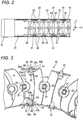
- FIG. 2 is a sectional view of a bending portion which is included in the insertion unit of the endoscope in FIG. 1
- FIG. 3 is a sectional view enlargedly showing the bending portion in FIG. 2 .
- the endoscope 1 includes a manipulation unit 3, an insertion unit 2 which is disposed in continuation to the manipulation unit 3 and which is inserted into a subject, and a universal cable 4 which extends from the manipulation unit 3.
- the universal cable 4 contains a light guide, a signal line, etc. not shown, and it is connected to a light source device, a signal processing device, etc. not shown, in a connector 5 which is disposed at its tail end.
- the insertion unit 2 includes a bending portion 12, a distal end portion 11 which is disposed in continuation to the distal end side of the bending portion 12, and a flexible soft portion 13 which is disposed in continuation to the base end side of the bending portion 12.
- the bending portion 12 is coupled to the manipulation unit 3 through the soft portion 13. The light guide and the signal line arrive at the distal end portion 11 via the manipulation unit 3, the soft portion 13 and the bending portion 12.
- a solid-state imaging element for example, a CCD image sensor is disposed in the distal end portion 11.
- a plurality of buttons 14 for controlling imaging by the solid-state imaging element of the distal end portion 11, etc., and knobs 15a and 15b for manipulating the bending of the bending portion 12, are disposed in the manipulation unit 3.
- Illumination light generated by the light source device is guided to the distal end portion 11 through the light guide, and it is projected on the subject.
- reflection light reflected from the subject is focused on the solid-state imaging element included in the distal end portion 11, whereby the image signal of the subject is generated.
- This image signal is sent to the signal processing device through the signal line.
- the signal processing device generates display image data by processing, for example, the inputted image signal, and it displays a subject image based on the generated display image data, on a monitor (not shown).
- the bending portion 12 has a plurality of articulation wheels 21 which are coupled in succession.
- Each of the articulation wheels 21 is a hard member which is formed into a substantially cylindrical shape.
- the articulation wheel 21 which forms one end of the array of these articulation wheels 21 is joined unitarily with the rear end part of the outer shell of the distal end portion 11.
- the outer shell of the distal end portion 11 and the plurality of articulation wheels 21 of the bending portion 12 are both covered with a flexible tube 24 such as rubber tube.
- Two of the articulation wheels 21 adjacent to each other are coupled by a shaft member 31 so as to be relatively turnable around the shaft member 31 on a direction crossing a center axis of the bending portion 12.
- the shaft members 31 are arranged so that their center axes may alternately extend in a first direction X which is orthogonal to the center axis Z of the bending portion 12, and a second direction Y which is orthogonal to the center axis of the bending portion 12 and which is also orthogonal to the first direction X.
- wires 16 are laid along the center axis of the bending portion 12 at intervals of about 90 degrees around this center axis.
- Insertional holes 33 which penetrate in a diametric direction are formed in those end parts of the shaft members 31 which protrude on the inside diameter sides of the articulation wheels 21, and each of the wires 16 is disposed by successively passing through the insertional holes 33 of the shaft members 31 arrayed in the axial direction of the bending portion 12.
- each wire 16 is secured by welding or the like appropriate means to the articulation wheel 21 which is joined unitarily with the outer shell of the distal end portion 11.
- the other end part of each wire 16 is connected to the knob 15a or 15b of the manipulation unit 3.
- one set of wires 16 which vertically oppose with the center axis of the bending portion 12 interposed therebetween in FIG. 2 correspond to the vertical bending (upward or downward bending) of the bending portion 12, and they are respectively connected to the knob 15a.
- the remaining set of wires 16 which horizontally oppose with the center axis of the bending portion 12 interposed therebetween correspond to the horizontal bending (rightward or leftward bending) of the bending portion 12, and they are respectively connected to the knob 15b.
- a pair of coupling parts 22 opposing to each other are respectively disposed at both the axial end parts of each articulation wheel 21.
- a pair of coupling parts 22 are disposed at only the end part of the articulation wheel on the side thereof on which the other articulation wheel 21 is coupled.
- the coupling part 22b of the other articulation wheel 21b is placed on the coupling part 22a of one articulation wheel 21a double inside and outside.
- the coupling part 22a located inside and the coupling part 22b located outside are respectively formed with shaft holes 23a and 23b through which the shaft member 31 is inserted.
- the shaft hole 23b of the coupling part 22b located outside is formed to be smaller in diameter than the shaft hole 23a of the coupling part 22a located inside.
- the shaft member 31 is inserted through the respective shaft holes 23a and 23b of both the coupling parts 22a and 22b placed one over the other, whereby both the articulation wheels 21a and 21b are coupled.
- the shaft member 31 includes a guide part 32 which is formed with an insertional hole 33 for inserting the wire 16 therethrough, a first shaft part 34 which extends from the guide part 32, and a second shaft part 35 which is provided in continuation to the distal end of the first shaft part 34 and coaxially with the first shaft part 34.
- a guide part 32 which is formed with an insertional hole 33 for inserting the wire 16 therethrough
- a first shaft part 34 which extends from the guide part 32
- a second shaft part 35 which is provided in continuation to the distal end of the first shaft part 34 and coaxially with the first shaft part 34.
- the first shaft part 34 is formed to be slightly smaller in diameter than the shaft hole 23a of the coupling part 22a located inside, and it is loosely fitted in the shaft hole 23a.
- the first shaft part 34 is formed to be larger in diameter than the shaft hole 23b of the coupling part 22b located outside, and it is held in engagement with the peripheral edge part of the shaft hole 23b at its end face.
- the second shaft part 35 is formed to be slightly smaller in diameter than the shaft hole 23b of the coupling part 22b located outside, and it is loosely fitted in the shaft hole 23b.
- the distal end part of the second shaft part 35 protrudes out of the coupling part 22b through the shaft hole 23b.
- the distal end part 36 protruding out of the coupling part 22b is plastically deformed into the shape of a flat disc so as to become larger in diameter than the shaft hole 23b, and it is made a nip part 37.
- the shaft member 31 formed with the nip part 37 is mounted on the coupling part 22b in such a manner that the peripheral edge part of the shaft hole 23b of the coupling part 22b is pinched in a direction in which both the coupling parts 22a and 22b are placed one over the other, between the first shaft part 34 and the nip part 37. That is, the first shaft part 34 forms a nip part which pairs with the nip part 37.
- a slight gap G is provided in the direction in which both the coupling parts 22a and 22b are placed one over the other, between the first shaft part 34 and the nip part 37 which function as the pair of nip parts of the shaft member 31 and the coupling part 22b which is pinched between the parts 34 and 37.
- the first shaft part 34 is loosely fitted into the shaft hole 23a of the coupling part 22a
- the second shaft part 35 is loosely fitted into the shaft hole 23b of the coupling part 22b
- the gap G is provided, whereby the shaft member 31 can rotate on its own axis, without being secured by either of the articulation wheels 21a and 21b.
- the whole shaft member 31 including the guide part 32 can rotate on its own axis, that is, it can turn to either of the articulation wheels 21a and 21b around its center axis. Moreover, both the articulation wheels 21a and 21b are relatively turnable around the center axis of the shaft member 31.
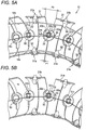
- FIG. 5A shows the state of the bending portion 12 in the case where the wire 16a disposed at the lower part of the bending portion 12 in the figure has been drawn.
- the two adjacent articulation wheels 21 coupled by the shaft members 31c juxtaposed at the side part of the bending portion 12 are relatively turned in a sense in which an interval P1 at the lower edges of these articulation wheels 21 is narrowed, so as to shorten the path length of the wire 16a stipulated by the guide parts 32 of the shaft members 31a juxtaposed at the lower part of the bending portion 12.
- the bending portion 12 is bent downwards.
- the wire 16c which is disposed at the side part of the bending portion 12 while being successively inserted through the insertional holes 33 that are formed in the guide parts 32 of the shaft members 31c juxtaposed at the side part of the bending portion 12, is appropriately inflected at the positions of the respective shaft members 31c in accordance with the bending of the bending portion 12.
- the wire 16c touches the edges 33a and 33b of the guide part 32 corresponding to both the ends of the insertional hole 33, and it is appropriately inflected at the edges 33a and 33b.
- the inflection angle ⁇ a of the wire 16c at one edge 33a of the guide part 32 and the inflection angle ⁇ b of the wire 16c at the other edge 33b become substantially equal.
- a force exerted on the wire 16c by the touch with the guide part 32 is distributed substantially equally to the part of the wire 16c touching one edge 33a and the part thereof touching the other edge 33b.
- FIG. 5B illustrates a case where the shaft member coupling the two adjacent articulation wheels has been secured to one articulation wheel, that is, a case where the shaft member including the guide part is unturnable to one articulation wheel.
- the whole shaft member 31 including the guide part 32 is turnable to both the two articulation wheels 21 to-be-coupled around its center axis, so that when both the articulation wheels 21 have been relatively turned, the wire can be equally inflected at both the edges of the guide part 32.
- the force exerted on the wire 16 by the touch with the guide part 32 can be distributed, and the wear of the wire 16 can be suppressed.
- FIGS. 6 through 8 show modifications of the shaft member which couples the two adjacent articulation wheels 21 of the bending portion 12.
- the shaft member 31 stated above is mounted on the coupling part 22b located outside, in the respective coupling parts 22a and 22b of the two adjacent articulation wheels 21a and 21b as are placed one over the other, in such a manner that the coupling part 22b is pinched between the pair of nip parts 34 and 37.
- the shaft member 41 shown in FIG. 6 is mounted on the coupling part 22a located inside, in such a manner that the coupling part 22a is pinched.
- the shaft hole 23a of the coupling part 22a located inside is formed to be smaller in diameter than the shaft hole 23b of the coupling part 22b located outside.
- the shaft member 41 includes a guide part 42 formed with an insertional hole 43 through which the wire 16 is inserted, and a shaft part 44 extended from the guide part 42.
- the guide part 42 is formed to be larger in diameter than the shaft hole 23a of the coupling part 22a located inside.
- the shaft part 44 is formed to be slightly smaller in diameter than the shaft hole 23a, and it is loosely fitted into the shaft hole 23a.
- the distal end part of the shaft part 44 protrudes out of the coupling part 22a through the shaft hole 23a.
- the distal end part protruding from the coupling part 22a is plastically deformed into the shape of a flat disc so as to become larger in diameter than the shaft hole 23a and slightly smaller in diameter than the shaft hole 23b of the coupling part 22b located outside, thereby to be made a nip part 47.
- the shaft member 41 formed with the nip part 47 is mounted on the coupling part 22a in such a manner that the peripheral edge part of the shaft hole 23a of the coupling part 22a is pinched in a direction in which both the coupling parts 22a and 22b are placed one over the other by the guide part 42 and the nip part 47. That is, the guide part 42 forms a nip part which pairs with the nip part 47.
- the nip part 47 is slightly smaller in diameter than the shaft hole 23b of the coupling part 22b located outside, and it is loosely fitted into the shaft hole 23b of the coupling part 22b located outside, thereby to function also as a shaft for the coupling part 22b.
- a slight gap G is provided in the direction in which both the coupling parts 22a and 22b are placed one over the other, between the guide part 42 and the nip part 47 which form the pair of nip parts of the shaft member 41 and the coupling part 22a which is pinched between these parts 42 and 47.
- the shaft part 44 is loosely fitted into the shaft hole 23a of the coupling part 22a
- the nip part 47 of the shaft part 44 is loosely fitted into the shaft hole 23b of the coupling part 22b
- the gap G is provided, whereby the shaft member 41 can rotate on its own axis without being secured to either of the articulation wheels 21a and 21b.
- the above gap G can be provided in such a way, for example, that a metal sheet or the like spacer is interposed between the guide part 42 and the coupling part 22a, that the distal end part of the shaft part 44 is caulked, and that the spacer is removed after the caulking.
- the whole shaft member 41 including the guide part 42 is turnable to both the two articulation wheels 21 to-be-coupled around its center axis, so that when both the articulation wheels 21 have been relatively turned, the wire can be equally inflected at both the edges of the guide part 42.
- a force exerted on the wire 16 by the touch with the guide part 42 can be distributed, and the wear of the wire 16 can be suppressed.
- the shaft member 51 shown in FIG. 7 is mounted pinching both the respective coupling parts 22a and 22b of the two adjacent articulation wheels 21a and 21b as are placed one over the other.
- the shaft holes 23a and 23b of both the coupling parts 22a and 22b are formed at an identical diameter.
- the shaft member 51 includes a guide part 52 formed with an insertional hole 53 through which the wire 16 is inserted, and a shaft part 54 extended from the guide part 52.
- the shaft member 51 formed with the nip part 57 is mounted in such a manner that the peripheral edge part of the shaft holes 23a and 23b of the coupling parts 22a and 22b are pinched in a direction in which both the coupling parts 22a and 22b are placed one over the other, between the guide part 52 and the nip part 57. That is, the guide part 52 forms a nip part which pairs with the nip part 57.
- a slight gap G is provided in the direction in which both the coupling parts 22a and 22b are placed one over the other, between the guide part 52 and the nip part 57 which form the pair of nip parts of the shaft member 51 and both the coupling parts 22a and 22b which are pinched between these parts 52 and 57.
- the shaft part 54 is loosely fitted into the shaft holes 23a and 23b of both the coupling parts 22a and 22b, and the gap G is provided, whereby the shaft member 51 can rotate on its own axis without being secured to either of the articulation wheels 21a and 21b.
- the above gap G can be provided in such a way, for example, that the distal end part of the shaft part 54 is caulked with a spacer interposed between the guide part 52 and the coupling part 22a, or with a spacer put on the coupling part 22b, and that the spacer is removed after the caulking.
- the shaft hole 23b of a coupling part 22b located outside, in the respective coupling parts 22a and 22b of the two adjacent articulation wheels 21a and 21b as are placed one over the other, is formed to be smaller in diameter than the shaft hole 23a of the coupling part 22a located inside.
- the shaft member 61 includes the guide part 62 formed with an insertional hole 63 through which the wire 16 is inserted, and a secured part 70.
- the guide part 62 and the secured part 70 are separate components, and they are connected to each other.
- the secured part 70 includes a first shaft part 64, and a second shaft part 65 which is disposed coaxially with the first shaft part 64 in continuation to the distal end of the first shaft part 64.
- the guide part 62 is provided with a spherical joint 69 which offers its connection with the secured part 70, and a socket 68 which accommodates the spherical joint 69 therein is provided at the base end part of the first shaft part 64 of the secured part 70.
- the guide part 62 with the spherical joint 69 accommodated in the socket 68 is supported by the secured part 70 so as to be turnable around the center axis of this secured part 70.
- the first shaft part 64 of the secured part 70 is formed to be slightly smaller in diameter than the shaft hole 23a of the coupling part 22a located inside, and it is loosely fitted into the shaft hole 23a.
- the first shaft part 64 is formed to be larger in diameter than the shaft hole 23b of the coupling part 22b located outside, and it is held in engagement with the peripheral edge part of the shaft hole 23b at its end face.
- the second shaft part 65 of the secured part 70 is inserted through the shaft hole 23b of the coupling part 22b located outside.
- the distal end part of the second shaft part 65 protrudes out of the coupling part 22b through the shaft hole 23b.
- the distal end part protruding from the coupling part 22b is plastically deformed into the shape of a flat disc so as to become larger in diameter than the shaft hole 23b, thereby to be made a nip part 67.
- the secured part 70 formed with the nip part 67 pinches the peripheral edge part of the shaft hole 23b of the coupling part 22b in a direction in which both the coupling parts 22a and 22b are placed one over the other, without any gap between the first shaft part 64 and the nip part 67, and it is secured to the coupling part 22b.
- the secured part 70 is secured to the coupling part 22b of one articulation wheel 21b, the first shaft part 64 of the secured part 70 is loosely fitted into the shaft hole 23a which is formed in the coupling part 22a of the other articulation wheel 21a. Therefore, the articulation wheel 21a is turnable to the articulation wheel 21b around the first shaft part 64 of the secured part 70.
- the guide part 62 which is turnably supported by the secured part 70 is turnable to both the articulation wheels 21a and 21b.
- the guide part 62 of the shaft member 61 is turnable to both the two articulation wheels 21a and 21b to-be-coupled around the center axis of the secured part 70, that is, the center axis of the shaft member 61, so that when both the articulation wheels 21a and 21b have been relatively turned, the wire can be equally inflected at both the edges of the guide part 62.
- a force exerted on the wire 16 by the touch with the guide part 62 can be distributed, and the wear of the wire 16 can be suppressed.
- the secured part 70 is secured to the coupling part 22b in such a manner that the peripheral edge part of the shaft hole 23b formed in the coupling part 22b of one articulation wheel 21b is pinched without any gap between the first shaft part 64 and the nip part 67, and the rattling of the shaft member 61 is prevented.
- the relative turning of both the articulation wheels 21a and 21b is done smoothly.
- the endoscope disclosed in this specification is one including a manipulation unit, and an insertion unit which is disposed in continuation to the manipulation unit, the insertion unit containing a bending portion which has a plurality of articulation wheels connected in succession, the two adjacent ones of the articulation wheels being coupled by a shaft member so as to be relatively turnable around the shaft member on a direction crossing a center axis of the bending portion, and the bending portion being bent in such a way that a wire which leads to the manipulation unit via the plurality of articulation wheels is tractively manipulated, wherein the shaft member has a guide part formed with an insertional hole through which the wire is inserted, and at least the guide part of the shaft member is turnable around the center axis of the shaft member, to both the two articulation wheels coupled by the shaft member.
- the guide part of the shaft member is turnable to both the two articulation wheels to-be-coupled, so that when both the articulation wheels have been relatively turned, the wire can be equally inflected at both the edges of the guide part.
- a force which is exerted on the wire by the touch thereof with the guide part can be distributed, and the wear of the wire can be suppressed.
- each of the plurality of articulation wheels has a coupling part formed with a shaft hole through which the shaft member is inserted, and the two adjacent articulation wheels are coupled in such a manner that the shaft member is inserted through the shaft holes of the respective coupling parts placed one over the other.
- the shaft member has a pair of nip parts pinching at least one of the two coupling parts placed one over the other, in a direction in which the coupling parts are placed, and a gap is put in the direction of the placement, between the pair of nip parts and the coupling part to be pinched by the pair of nip parts.
- the shaft member is mounted without being secured to either of the two articulation wheels to-be-coupled, and the whole shaft member including the guide part becomes turnable to both the articulation wheels around its center axis.
- the whole shaft member including the guide part can be unitarily formed, and it can be simplified in configuration.
- the shaft member further has a secured part which is secured to either of the two coupling parts placed one over the other, and the guide part is separated from the secured part and is supported by this secured part so as to be turnable around the axis of the shaft member. According to this endoscope, the rattling of the shaft member can be prevented, and the relative turning of the two articulation wheels which are coupled by the shaft member is done smoothly.
Landscapes
- Health & Medical Sciences (AREA)
- Life Sciences & Earth Sciences (AREA)
- Physics & Mathematics (AREA)
- Surgery (AREA)
- Optics & Photonics (AREA)
- Biomedical Technology (AREA)
- Animal Behavior & Ethology (AREA)
- Radiology & Medical Imaging (AREA)
- Nuclear Medicine, Radiotherapy & Molecular Imaging (AREA)
- Engineering & Computer Science (AREA)
- Biophysics (AREA)
- Heart & Thoracic Surgery (AREA)
- Medical Informatics (AREA)
- Molecular Biology (AREA)
- Pathology (AREA)
- General Health & Medical Sciences (AREA)
- Public Health (AREA)
- Veterinary Medicine (AREA)
- Astronomy & Astrophysics (AREA)
- General Physics & Mathematics (AREA)
- Rehabilitation Therapy (AREA)
- Endoscopes (AREA)
- Instruments For Viewing The Inside Of Hollow Bodies (AREA)
Claims (2)
- Endoskop (1), umfassend:eine Manipuliereinheit (3); undeine Einführeinheit (2), die als Fortsetzung der Manipuliereinheit (3) angeordnet ist und einen Biegebereich (12) enthält,wobei die Einführeinheit (2) innerhalb des Biegebereichs (12) aufweist:mehrere aufeinanderfolgend gekoppelte Gelenkräder (21); undmehrere Achsenelemente (61), von denen jedes Achsenelement (61) einen Führungsteil (62) enthält, der mit einem Einführloch (63) ausgebildet ist, durch welches ein Draht (16) eingeführt wird, wobei vier Drähte (16) entlang der Mittelachse des Biegebereichs (12) verlegt sind;wobei zwei benachbarte (21a, 21b) der mehreren Gelenkräder (21) durch Achsenelemente (61) derart gekoppelt sind, dass sie um die Achselemente (61) herum in einer Richtung relativ zueinander verschwenkbar sind, welche eine Mittelachse des Biegebereichs (12) kreuzt,der Biegebereich (12) derart gebogen wird, dass der Draht (16), der über die mehreren Gelenkräder (21) zu der Manipuliereinheit (2) führt, durch Zug manipuliert wird,jedes Führungsteil (62) der Achsenelemente (61) um eine Mittelachse jedes Achsenelements (61) drehbar ist in Bezug auf beide von zwei Gelenkrädern (21a, 21b), die durch zwei Achsenelemente (61) gekoppelt sind, wobei jedes der mehreren Gelenkräder (61) einen Kupplungsteil (22a, 22b) aufweist, der mit einem Achsloch (23a, 23b) ausgebildet ist, durch die das Achsenelement (61) eingeführt wird, die zwei benachbarten Gelenkräder (21) derart gekoppelt sind, dass das Achsenelement (31, 41, 51) durch die Achslöcher (23a, 23b) der betreffenden beiden Kupplungsteile eingeführt wird, die übereinander platziert sind, wobeijedes Achsenelement (61) weiterhin einen Sicherungsteil (70) enthält, der Führungsteil (62) und der Sicherungsteil (70) jedes Achsenelements (61) getrennte Bauteile sind, die miteinander verbunden sind, und wobei die Sicherungsteile (70) an einem der beiden Kupplungsteile (22a, 22b), die übereinander gelegt sind, festgelegt sind,dadurch gekennzeichnet, dassder Führungsteil (62) mit einer kugelförmigen Verbindung (69) ausgestattet ist, und der Sicherungsteil (70) eine Fassung (68) aufweist, wobei für jedes Achsenelement (61) die Fassung (68) des betreffenden Sicherungsteils (70) die kugelförmige Verbindung (69) des entsprechenden Führungsteils (62) aufnimmt, so dass der Führungsteil (62) um die Mittelachse des Sicherungsteils (70) drehbar ist.
- Endoskop nach Anspruch 1, bei dem
der Führungsteil (32, 42, 52) eine kugelförmige Verbindung enthält, ausgebildet zur Schaffung einer Verbindung mit dem Sicherungsteil (70),
der Sicherungsteil (70) eine Fassung enthält, welche in sich die kugelförmige Verbindung (69) aufnimmt, und
der Führungsteil (62) mit der in der Fassung (68) aufgenommenen kugelförmigen Verbindung (69) von dem Sicherungsteil (72) so gelagert wird, dass er um die Mittelachse des Sicherungsteils drehbar ist.
Applications Claiming Priority (1)
| Application Number | Priority Date | Filing Date | Title |
|---|---|---|---|
| JP2009014253A JP2010167180A (ja) | 2009-01-26 | 2009-01-26 | 内視鏡 |
Publications (2)
| Publication Number | Publication Date |
|---|---|
| EP2210550A1 EP2210550A1 (de) | 2010-07-28 |
| EP2210550B1 true EP2210550B1 (de) | 2017-10-25 |
Family
ID=42173905
Family Applications (1)
| Application Number | Title | Priority Date | Filing Date |
|---|---|---|---|
| EP10151562.5A Not-in-force EP2210550B1 (de) | 2009-01-26 | 2010-01-25 | Endoskop mit distalem Krümmungsabschnitt |
Country Status (3)
| Country | Link |
|---|---|
| US (1) | US8444552B2 (de) |
| EP (1) | EP2210550B1 (de) |
| JP (1) | JP2010167180A (de) |
Families Citing this family (13)
| Publication number | Priority date | Publication date | Assignee | Title |
|---|---|---|---|---|
| US8052597B2 (en) * | 2005-08-30 | 2011-11-08 | Boston Scientific Scimed, Inc. | Method for forming an endoscope articulation joint |
| JP5420355B2 (ja) * | 2009-09-10 | 2014-02-19 | オリンパス株式会社 | 内視鏡湾曲部 |
| US9119639B2 (en) * | 2011-08-09 | 2015-09-01 | DePuy Synthes Products, Inc. | Articulated cavity creator |
| JP5734786B2 (ja) * | 2011-08-10 | 2015-06-17 | オリンパス株式会社 | 内視鏡 |
| US9439693B2 (en) | 2013-02-01 | 2016-09-13 | DePuy Synthes Products, Inc. | Steerable needle assembly for use in vertebral body augmentation |
| CN103690140A (zh) * | 2014-01-10 | 2014-04-02 | 上海欧太医疗器械有限公司 | 内窥镜接节圈、内窥镜弯曲部及相应的内窥镜装置 |
| JP5970135B2 (ja) * | 2014-08-06 | 2016-08-17 | オリンパス株式会社 | 内視鏡 |
| CN107072472B (zh) * | 2014-10-06 | 2019-07-12 | 奥林巴斯株式会社 | 内窥镜 |
| JP2018166675A (ja) * | 2017-03-29 | 2018-11-01 | 富士フイルム株式会社 | 操作機構、内視鏡、及び製造方法 |
| CN107088046B (zh) * | 2017-06-12 | 2019-07-09 | 上海成运医疗器械股份有限公司 | 内窥镜用蛇骨 |
| US11793396B2 (en) * | 2018-01-11 | 2023-10-24 | The General Hospital Corporation | Devices, systems, and methods for advancing and positioning tethered capsule microendoscopes |
| CN108553069B (zh) * | 2018-05-17 | 2020-08-28 | 黄琴 | 可控弯曲管结构 |
| CN211749473U (zh) * | 2019-12-31 | 2020-10-27 | 湖南省华芯医疗器械有限公司 | 一种灵活弯折的内窥镜用蛇管 |
Family Cites Families (7)
| Publication number | Priority date | Publication date | Assignee | Title |
|---|---|---|---|---|
| US4108211A (en) * | 1975-04-28 | 1978-08-22 | Fuji Photo Optical Co., Ltd. | Articulated, four-way bendable tube structure |
| JPH01120804U (de) * | 1988-02-08 | 1989-08-16 | ||
| JP2532380Y2 (ja) * | 1990-10-09 | 1997-04-16 | 富士写真光機株式会社 | 内視鏡のアングルリング連結ピン |
| JP2000316800A (ja) * | 1999-05-12 | 2000-11-21 | Fuji Photo Optical Co Ltd | 内視鏡の湾曲部構造 |
| US6482149B1 (en) | 1999-05-12 | 2002-11-19 | Fuji Photo Optical Co., Ltd. | Curved part of endoscope |
| JP3835077B2 (ja) | 1999-09-30 | 2006-10-18 | フジノン株式会社 | 操作ワイヤの端部処理方法 |
| JP2002078674A (ja) * | 2000-09-08 | 2002-03-19 | Fuji Photo Optical Co Ltd | 内視鏡の湾曲部構造 |
-
2009
- 2009-01-26 JP JP2009014253A patent/JP2010167180A/ja not_active Abandoned
-
2010
- 2010-01-25 US US12/693,160 patent/US8444552B2/en not_active Expired - Fee Related
- 2010-01-25 EP EP10151562.5A patent/EP2210550B1/de not_active Not-in-force
Non-Patent Citations (1)
| Title |
|---|
| None * |
Also Published As
| Publication number | Publication date |
|---|---|
| JP2010167180A (ja) | 2010-08-05 |
| US8444552B2 (en) | 2013-05-21 |
| US20100191058A1 (en) | 2010-07-29 |
| EP2210550A1 (de) | 2010-07-28 |
Similar Documents
| Publication | Publication Date | Title |
|---|---|---|
| EP2210550B1 (de) | Endoskop mit distalem Krümmungsabschnitt | |
| EP1554972B1 (de) | Endoskopvorrichtung | |
| CN101133934B (zh) | 内窥镜用摄像组件 | |
| JP5871217B2 (ja) | 内視鏡 | |
| CN105636494A (zh) | 内窥镜的弯曲部 | |
| JP6655343B2 (ja) | 内視鏡 | |
| JP2002153465A (ja) | 超音波内視鏡 | |
| JP4981379B2 (ja) | 内視鏡 | |
| WO2018079061A1 (ja) | 内視鏡 | |
| CN107105979A (zh) | 内窥镜 | |
| CN107920866B (zh) | 医疗观察装置和医疗观察系统 | |
| WO2016035359A1 (ja) | 内視鏡 | |
| JP2018200417A (ja) | 撮像装置及び内視鏡装置 | |
| US20170150879A1 (en) | Bendable tube segment, bendable tube and insertion device | |
| JP2018102714A (ja) | 内視鏡用光学アダプタおよび内視鏡装置 | |
| JP2010175962A (ja) | 内視鏡装置 | |
| JPH1156760A (ja) | 内視鏡 | |
| JP5622884B2 (ja) | 内視鏡 | |
| CN218528690U (zh) | 一种内窥镜 | |
| EP4334796B1 (de) | Videoverarbeitungsgerät | |
| JPH10286229A (ja) | 内視鏡用撮像装置 | |
| JP4355022B2 (ja) | 可撓性内視鏡 | |
| JP3220928B2 (ja) | 内視鏡 | |
| JP2009000506A (ja) | 内視鏡 | |
| JP3762600B2 (ja) | 電子内視鏡 |
Legal Events
| Date | Code | Title | Description |
|---|---|---|---|
| PUAI | Public reference made under article 153(3) epc to a published international application that has entered the european phase |
Free format text: ORIGINAL CODE: 0009012 |
|
| AK | Designated contracting states |
Kind code of ref document: A1 Designated state(s): AT BE BG CH CY CZ DE DK EE ES FI FR GB GR HR HU IE IS IT LI LT LU LV MC MK MT NL NO PL PT RO SE SI SK SM TR |
|
| AX | Request for extension of the european patent |
Extension state: AL BA RS |
|
| 17P | Request for examination filed |
Effective date: 20110126 |
|
| 17Q | First examination report despatched |
Effective date: 20111028 |
|
| RIC1 | Information provided on ipc code assigned before grant |
Ipc: A61B 1/005 20060101AFI20161028BHEP Ipc: A61B 1/008 20060101ALI20161028BHEP Ipc: A61B 1/012 20060101ALN20161028BHEP Ipc: G02B 23/24 20060101ALI20161028BHEP |
|
| RIC1 | Information provided on ipc code assigned before grant |
Ipc: A61B 1/012 20060101ALN20161206BHEP Ipc: A61B 1/005 20060101AFI20161206BHEP Ipc: G02B 23/24 20060101ALI20161206BHEP Ipc: A61B 1/008 20060101ALI20161206BHEP |
|
| GRAP | Despatch of communication of intention to grant a patent |
Free format text: ORIGINAL CODE: EPIDOSNIGR1 |
|
| STAA | Information on the status of an ep patent application or granted ep patent |
Free format text: STATUS: GRANT OF PATENT IS INTENDED |
|
| INTG | Intention to grant announced |
Effective date: 20170119 |
|
| GRAS | Grant fee paid |
Free format text: ORIGINAL CODE: EPIDOSNIGR3 |
|
| GRAJ | Information related to disapproval of communication of intention to grant by the applicant or resumption of examination proceedings by the epo deleted |
Free format text: ORIGINAL CODE: EPIDOSDIGR1 |
|
| GRAL | Information related to payment of fee for publishing/printing deleted |
Free format text: ORIGINAL CODE: EPIDOSDIGR3 |
|
| STAA | Information on the status of an ep patent application or granted ep patent |
Free format text: STATUS: EXAMINATION IS IN PROGRESS |
|
| INTC | Intention to grant announced (deleted) | ||
| RIC1 | Information provided on ipc code assigned before grant |
Ipc: G02B 23/24 20060101ALI20170602BHEP Ipc: A61B 1/008 20060101ALI20170602BHEP Ipc: A61B 1/012 20060101ALN20170602BHEP Ipc: A61B 1/005 20060101AFI20170602BHEP |
|
| GRAP | Despatch of communication of intention to grant a patent |
Free format text: ORIGINAL CODE: EPIDOSNIGR1 |
|
| STAA | Information on the status of an ep patent application or granted ep patent |
Free format text: STATUS: GRANT OF PATENT IS INTENDED |
|
| INTG | Intention to grant announced |
Effective date: 20170728 |
|
| GRAA | (expected) grant |
Free format text: ORIGINAL CODE: 0009210 |
|
| STAA | Information on the status of an ep patent application or granted ep patent |
Free format text: STATUS: THE PATENT HAS BEEN GRANTED |
|
| AK | Designated contracting states |
Kind code of ref document: B1 Designated state(s): AT BE BG CH CY CZ DE DK EE ES FI FR GB GR HR HU IE IS IT LI LT LU LV MC MK MT NL NO PL PT RO SE SI SK SM TR |
|
| REG | Reference to a national code |
Ref country code: GB Ref legal event code: FG4D |
|
| REG | Reference to a national code |
Ref country code: CH Ref legal event code: EP |
|
| REG | Reference to a national code |
Ref country code: AT Ref legal event code: REF Ref document number: 939096 Country of ref document: AT Kind code of ref document: T Effective date: 20171115 |
|
| REG | Reference to a national code |
Ref country code: IE Ref legal event code: FG4D |
|
| REG | Reference to a national code |
Ref country code: DE Ref legal event code: R096 Ref document number: 602010046138 Country of ref document: DE |
|
| REG | Reference to a national code |
Ref country code: FR Ref legal event code: PLFP Year of fee payment: 9 |
|
| REG | Reference to a national code |
Ref country code: NL Ref legal event code: MP Effective date: 20171025 |
|
| REG | Reference to a national code |
Ref country code: LT Ref legal event code: MG4D |
|
| REG | Reference to a national code |
Ref country code: AT Ref legal event code: MK05 Ref document number: 939096 Country of ref document: AT Kind code of ref document: T Effective date: 20171025 |
|
| PG25 | Lapsed in a contracting state [announced via postgrant information from national office to epo] |
Ref country code: NL Free format text: LAPSE BECAUSE OF FAILURE TO SUBMIT A TRANSLATION OF THE DESCRIPTION OR TO PAY THE FEE WITHIN THE PRESCRIBED TIME-LIMIT Effective date: 20171025 |
|
| PG25 | Lapsed in a contracting state [announced via postgrant information from national office to epo] |
Ref country code: LT Free format text: LAPSE BECAUSE OF FAILURE TO SUBMIT A TRANSLATION OF THE DESCRIPTION OR TO PAY THE FEE WITHIN THE PRESCRIBED TIME-LIMIT Effective date: 20171025 Ref country code: FI Free format text: LAPSE BECAUSE OF FAILURE TO SUBMIT A TRANSLATION OF THE DESCRIPTION OR TO PAY THE FEE WITHIN THE PRESCRIBED TIME-LIMIT Effective date: 20171025 Ref country code: NO Free format text: LAPSE BECAUSE OF FAILURE TO SUBMIT A TRANSLATION OF THE DESCRIPTION OR TO PAY THE FEE WITHIN THE PRESCRIBED TIME-LIMIT Effective date: 20180125 Ref country code: ES Free format text: LAPSE BECAUSE OF FAILURE TO SUBMIT A TRANSLATION OF THE DESCRIPTION OR TO PAY THE FEE WITHIN THE PRESCRIBED TIME-LIMIT Effective date: 20171025 Ref country code: SE Free format text: LAPSE BECAUSE OF FAILURE TO SUBMIT A TRANSLATION OF THE DESCRIPTION OR TO PAY THE FEE WITHIN THE PRESCRIBED TIME-LIMIT Effective date: 20171025 |
|
| PG25 | Lapsed in a contracting state [announced via postgrant information from national office to epo] |
Ref country code: BG Free format text: LAPSE BECAUSE OF FAILURE TO SUBMIT A TRANSLATION OF THE DESCRIPTION OR TO PAY THE FEE WITHIN THE PRESCRIBED TIME-LIMIT Effective date: 20180125 Ref country code: GR Free format text: LAPSE BECAUSE OF FAILURE TO SUBMIT A TRANSLATION OF THE DESCRIPTION OR TO PAY THE FEE WITHIN THE PRESCRIBED TIME-LIMIT Effective date: 20180126 Ref country code: IS Free format text: LAPSE BECAUSE OF FAILURE TO SUBMIT A TRANSLATION OF THE DESCRIPTION OR TO PAY THE FEE WITHIN THE PRESCRIBED TIME-LIMIT Effective date: 20180225 Ref country code: LV Free format text: LAPSE BECAUSE OF FAILURE TO SUBMIT A TRANSLATION OF THE DESCRIPTION OR TO PAY THE FEE WITHIN THE PRESCRIBED TIME-LIMIT Effective date: 20171025 Ref country code: HR Free format text: LAPSE BECAUSE OF FAILURE TO SUBMIT A TRANSLATION OF THE DESCRIPTION OR TO PAY THE FEE WITHIN THE PRESCRIBED TIME-LIMIT Effective date: 20171025 Ref country code: AT Free format text: LAPSE BECAUSE OF FAILURE TO SUBMIT A TRANSLATION OF THE DESCRIPTION OR TO PAY THE FEE WITHIN THE PRESCRIBED TIME-LIMIT Effective date: 20171025 Ref country code: PT Free format text: LAPSE BECAUSE OF FAILURE TO SUBMIT A TRANSLATION OF THE DESCRIPTION OR TO PAY THE FEE WITHIN THE PRESCRIBED TIME-LIMIT Effective date: 20180226 |
|
| REG | Reference to a national code |
Ref country code: DE Ref legal event code: R097 Ref document number: 602010046138 Country of ref document: DE |
|
| PG25 | Lapsed in a contracting state [announced via postgrant information from national office to epo] |
Ref country code: CZ Free format text: LAPSE BECAUSE OF FAILURE TO SUBMIT A TRANSLATION OF THE DESCRIPTION OR TO PAY THE FEE WITHIN THE PRESCRIBED TIME-LIMIT Effective date: 20171025 Ref country code: SK Free format text: LAPSE BECAUSE OF FAILURE TO SUBMIT A TRANSLATION OF THE DESCRIPTION OR TO PAY THE FEE WITHIN THE PRESCRIBED TIME-LIMIT Effective date: 20171025 Ref country code: EE Free format text: LAPSE BECAUSE OF FAILURE TO SUBMIT A TRANSLATION OF THE DESCRIPTION OR TO PAY THE FEE WITHIN THE PRESCRIBED TIME-LIMIT Effective date: 20171025 Ref country code: CY Free format text: LAPSE BECAUSE OF FAILURE TO SUBMIT A TRANSLATION OF THE DESCRIPTION OR TO PAY THE FEE WITHIN THE PRESCRIBED TIME-LIMIT Effective date: 20171025 Ref country code: DK Free format text: LAPSE BECAUSE OF FAILURE TO SUBMIT A TRANSLATION OF THE DESCRIPTION OR TO PAY THE FEE WITHIN THE PRESCRIBED TIME-LIMIT Effective date: 20171025 |
|
| PG25 | Lapsed in a contracting state [announced via postgrant information from national office to epo] |
Ref country code: RO Free format text: LAPSE BECAUSE OF FAILURE TO SUBMIT A TRANSLATION OF THE DESCRIPTION OR TO PAY THE FEE WITHIN THE PRESCRIBED TIME-LIMIT Effective date: 20171025 Ref country code: IT Free format text: LAPSE BECAUSE OF FAILURE TO SUBMIT A TRANSLATION OF THE DESCRIPTION OR TO PAY THE FEE WITHIN THE PRESCRIBED TIME-LIMIT Effective date: 20171025 Ref country code: SM Free format text: LAPSE BECAUSE OF FAILURE TO SUBMIT A TRANSLATION OF THE DESCRIPTION OR TO PAY THE FEE WITHIN THE PRESCRIBED TIME-LIMIT Effective date: 20171025 Ref country code: PL Free format text: LAPSE BECAUSE OF FAILURE TO SUBMIT A TRANSLATION OF THE DESCRIPTION OR TO PAY THE FEE WITHIN THE PRESCRIBED TIME-LIMIT Effective date: 20171025 |
|
| PLBE | No opposition filed within time limit |
Free format text: ORIGINAL CODE: 0009261 |
|
| REG | Reference to a national code |
Ref country code: CH Ref legal event code: PL |
|
| STAA | Information on the status of an ep patent application or granted ep patent |
Free format text: STATUS: NO OPPOSITION FILED WITHIN TIME LIMIT |
|
| 26N | No opposition filed |
Effective date: 20180726 |
|
| PG25 | Lapsed in a contracting state [announced via postgrant information from national office to epo] |
Ref country code: LU Free format text: LAPSE BECAUSE OF NON-PAYMENT OF DUE FEES Effective date: 20180125 |
|
| REG | Reference to a national code |
Ref country code: IE Ref legal event code: MM4A |
|
| REG | Reference to a national code |
Ref country code: BE Ref legal event code: MM Effective date: 20180131 |
|
| PG25 | Lapsed in a contracting state [announced via postgrant information from national office to epo] |
Ref country code: LI Free format text: LAPSE BECAUSE OF NON-PAYMENT OF DUE FEES Effective date: 20180131 Ref country code: BE Free format text: LAPSE BECAUSE OF NON-PAYMENT OF DUE FEES Effective date: 20180131 Ref country code: CH Free format text: LAPSE BECAUSE OF NON-PAYMENT OF DUE FEES Effective date: 20180131 Ref country code: SI Free format text: LAPSE BECAUSE OF FAILURE TO SUBMIT A TRANSLATION OF THE DESCRIPTION OR TO PAY THE FEE WITHIN THE PRESCRIBED TIME-LIMIT Effective date: 20171025 |
|
| PG25 | Lapsed in a contracting state [announced via postgrant information from national office to epo] |
Ref country code: IE Free format text: LAPSE BECAUSE OF NON-PAYMENT OF DUE FEES Effective date: 20180125 |
|
| PG25 | Lapsed in a contracting state [announced via postgrant information from national office to epo] |
Ref country code: MC Free format text: LAPSE BECAUSE OF FAILURE TO SUBMIT A TRANSLATION OF THE DESCRIPTION OR TO PAY THE FEE WITHIN THE PRESCRIBED TIME-LIMIT Effective date: 20171025 |
|
| PG25 | Lapsed in a contracting state [announced via postgrant information from national office to epo] |
Ref country code: MT Free format text: LAPSE BECAUSE OF NON-PAYMENT OF DUE FEES Effective date: 20180125 |
|
| PG25 | Lapsed in a contracting state [announced via postgrant information from national office to epo] |
Ref country code: TR Free format text: LAPSE BECAUSE OF FAILURE TO SUBMIT A TRANSLATION OF THE DESCRIPTION OR TO PAY THE FEE WITHIN THE PRESCRIBED TIME-LIMIT Effective date: 20171025 |
|
| PG25 | Lapsed in a contracting state [announced via postgrant information from national office to epo] |
Ref country code: HU Free format text: LAPSE BECAUSE OF FAILURE TO SUBMIT A TRANSLATION OF THE DESCRIPTION OR TO PAY THE FEE WITHIN THE PRESCRIBED TIME-LIMIT; INVALID AB INITIO Effective date: 20100125 |
|
| PG25 | Lapsed in a contracting state [announced via postgrant information from national office to epo] |
Ref country code: MK Free format text: LAPSE BECAUSE OF NON-PAYMENT OF DUE FEES Effective date: 20171025 |
|
| PGFP | Annual fee paid to national office [announced via postgrant information from national office to epo] |
Ref country code: FR Payment date: 20201210 Year of fee payment: 12 |
|
| PGFP | Annual fee paid to national office [announced via postgrant information from national office to epo] |
Ref country code: GB Payment date: 20210113 Year of fee payment: 12 |
|
| GBPC | Gb: european patent ceased through non-payment of renewal fee |
Effective date: 20220125 |
|
| PG25 | Lapsed in a contracting state [announced via postgrant information from national office to epo] |
Ref country code: GB Free format text: LAPSE BECAUSE OF NON-PAYMENT OF DUE FEES Effective date: 20220125 |
|
| PG25 | Lapsed in a contracting state [announced via postgrant information from national office to epo] |
Ref country code: FR Free format text: LAPSE BECAUSE OF NON-PAYMENT OF DUE FEES Effective date: 20220131 |
|
| P01 | Opt-out of the competence of the unified patent court (upc) registered |
Effective date: 20230515 |
|
| PGFP | Annual fee paid to national office [announced via postgrant information from national office to epo] |
Ref country code: DE Payment date: 20231128 Year of fee payment: 15 |
|
| REG | Reference to a national code |
Ref country code: DE Ref legal event code: R119 Ref document number: 602010046138 Country of ref document: DE |
|
| PG25 | Lapsed in a contracting state [announced via postgrant information from national office to epo] |
Ref country code: DE Free format text: LAPSE BECAUSE OF NON-PAYMENT OF DUE FEES Effective date: 20250801 |