EP2209554B1 - Modulare sensorkassette - Google Patents
Modulare sensorkassette Download PDFInfo
- Publication number
- EP2209554B1 EP2209554B1 EP08849867.0A EP08849867A EP2209554B1 EP 2209554 B1 EP2209554 B1 EP 2209554B1 EP 08849867 A EP08849867 A EP 08849867A EP 2209554 B1 EP2209554 B1 EP 2209554B1
- Authority
- EP
- European Patent Office
- Prior art keywords
- sensor
- modules
- sensor cassette
- cassette
- module
- Prior art date
- Legal status (The legal status is an assumption and is not a legal conclusion. Google has not performed a legal analysis and makes no representation as to the accuracy of the status listed.)
- Active
Links
- 230000001953 sensory effect Effects 0.000 claims description 68
- 230000003287 optical effect Effects 0.000 claims description 23
- 239000012530 fluid Substances 0.000 claims description 20
- 238000003860 storage Methods 0.000 claims description 12
- 238000007789 sealing Methods 0.000 claims description 11
- 238000004519 manufacturing process Methods 0.000 claims description 10
- 230000008878 coupling Effects 0.000 claims description 7
- 238000010168 coupling process Methods 0.000 claims description 7
- 238000005859 coupling reaction Methods 0.000 claims description 7
- 239000000126 substance Substances 0.000 claims description 4
- 238000004026 adhesive bonding Methods 0.000 claims description 3
- 238000004458 analytical method Methods 0.000 claims description 3
- 238000003780 insertion Methods 0.000 claims description 3
- 230000037431 insertion Effects 0.000 claims description 3
- 238000003466 welding Methods 0.000 claims description 3
- 230000006378 damage Effects 0.000 claims description 2
- 238000009751 slip forming Methods 0.000 claims 1
- 239000003792 electrolyte Substances 0.000 description 18
- 238000001514 detection method Methods 0.000 description 17
- 239000002207 metabolite Substances 0.000 description 12
- 239000008280 blood Substances 0.000 description 10
- 210000004369 blood Anatomy 0.000 description 10
- 238000006243 chemical reaction Methods 0.000 description 9
- 239000007789 gas Substances 0.000 description 8
- 238000000034 method Methods 0.000 description 8
- 239000003153 chemical reaction reagent Substances 0.000 description 7
- 238000005259 measurement Methods 0.000 description 7
- 239000012491 analyte Substances 0.000 description 6
- 239000007788 liquid Substances 0.000 description 6
- 102000001554 Hemoglobins Human genes 0.000 description 5
- 108010054147 Hemoglobins Proteins 0.000 description 5
- BPYKTIZUTYGOLE-IFADSCNNSA-N Bilirubin Chemical compound N1C(=O)C(C)=C(C=C)\C1=C\C1=C(C)C(CCC(O)=O)=C(CC2=C(C(C)=C(\C=C/3C(=C(C=C)C(=O)N\3)C)N2)CCC(O)=O)N1 BPYKTIZUTYGOLE-IFADSCNNSA-N 0.000 description 4
- WQZGKKKJIJFFOK-GASJEMHNSA-N Glucose Natural products OC[C@H]1OC(O)[C@H](O)[C@@H](O)[C@@H]1O WQZGKKKJIJFFOK-GASJEMHNSA-N 0.000 description 4
- JVTAAEKCZFNVCJ-UHFFFAOYSA-M Lactate Chemical compound CC(O)C([O-])=O JVTAAEKCZFNVCJ-UHFFFAOYSA-M 0.000 description 4
- WQZGKKKJIJFFOK-VFUOTHLCSA-N beta-D-glucose Chemical compound OC[C@H]1O[C@@H](O)[C@H](O)[C@@H](O)[C@@H]1O WQZGKKKJIJFFOK-VFUOTHLCSA-N 0.000 description 4
- DDRJAANPRJIHGJ-UHFFFAOYSA-N creatinine Chemical compound CN1CC(=O)NC1=N DDRJAANPRJIHGJ-UHFFFAOYSA-N 0.000 description 4
- 238000013461 design Methods 0.000 description 4
- 239000008103 glucose Substances 0.000 description 4
- 230000008901 benefit Effects 0.000 description 3
- 230000005540 biological transmission Effects 0.000 description 3
- 238000002848 electrochemical method Methods 0.000 description 3
- 238000006911 enzymatic reaction Methods 0.000 description 3
- 230000006870 function Effects 0.000 description 3
- 238000012123 point-of-care testing Methods 0.000 description 3
- 238000004611 spectroscopical analysis Methods 0.000 description 3
- XSQUKJJJFZCRTK-UHFFFAOYSA-N Urea Chemical compound NC(N)=O XSQUKJJJFZCRTK-UHFFFAOYSA-N 0.000 description 2
- 230000004913 activation Effects 0.000 description 2
- 239000004202 carbamide Substances 0.000 description 2
- 230000000747 cardiac effect Effects 0.000 description 2
- 239000007795 chemical reaction product Substances 0.000 description 2
- 230000015271 coagulation Effects 0.000 description 2
- 238000005345 coagulation Methods 0.000 description 2
- 229940109239 creatinine Drugs 0.000 description 2
- 238000003748 differential diagnosis Methods 0.000 description 2
- 230000000694 effects Effects 0.000 description 2
- 208000019622 heart disease Diseases 0.000 description 2
- 238000005534 hematocrit Methods 0.000 description 2
- 230000001900 immune effect Effects 0.000 description 2
- 230000003993 interaction Effects 0.000 description 2
- 239000000463 material Substances 0.000 description 2
- 239000012528 membrane Substances 0.000 description 2
- 230000008569 process Effects 0.000 description 2
- 238000000926 separation method Methods 0.000 description 2
- 239000007787 solid Substances 0.000 description 2
- 239000000758 substrate Substances 0.000 description 2
- 238000005496 tempering Methods 0.000 description 2
- 206010002091 Anaesthesia Diseases 0.000 description 1
- 208000020446 Cardiac disease Diseases 0.000 description 1
- 230000037005 anaesthesia Effects 0.000 description 1
- 238000003491 array Methods 0.000 description 1
- 230000023555 blood coagulation Effects 0.000 description 1
- 238000004820 blood count Methods 0.000 description 1
- 210000001124 body fluid Anatomy 0.000 description 1
- 239000010839 body fluid Substances 0.000 description 1
- 230000036760 body temperature Effects 0.000 description 1
- 239000000969 carrier Substances 0.000 description 1
- 238000009535 clinical urine test Methods 0.000 description 1
- 239000004020 conductor Substances 0.000 description 1
- 238000010276 construction Methods 0.000 description 1
- 238000001816 cooling Methods 0.000 description 1
- 238000007435 diagnostic evaluation Methods 0.000 description 1
- 238000000502 dialysis Methods 0.000 description 1
- 208000037265 diseases, disorders, signs and symptoms Diseases 0.000 description 1
- 239000003814 drug Substances 0.000 description 1
- 238000000835 electrochemical detection Methods 0.000 description 1
- 230000005284 excitation Effects 0.000 description 1
- 238000003384 imaging method Methods 0.000 description 1
- 239000011810 insulating material Substances 0.000 description 1
- 150000002500 ions Chemical class 0.000 description 1
- 230000003907 kidney function Effects 0.000 description 1
- 238000002156 mixing Methods 0.000 description 1
- 244000052769 pathogen Species 0.000 description 1
- 230000002572 peristaltic effect Effects 0.000 description 1
- 238000005375 photometry Methods 0.000 description 1
- 108010008064 pro-brain natriuretic peptide (1-76) Proteins 0.000 description 1
- 238000003908 quality control method Methods 0.000 description 1
- 230000005855 radiation Effects 0.000 description 1
- 230000009467 reduction Effects 0.000 description 1
- 230000004044 response Effects 0.000 description 1
- 238000001228 spectrum Methods 0.000 description 1
- 230000002123 temporal effect Effects 0.000 description 1
- 238000012360 testing method Methods 0.000 description 1
- 230000001960 triggered effect Effects 0.000 description 1
- 238000005406 washing Methods 0.000 description 1
- 239000002699 waste material Substances 0.000 description 1
Images
Classifications
-
- G—PHYSICS
- G01—MEASURING; TESTING
- G01N—INVESTIGATING OR ANALYSING MATERIALS BY DETERMINING THEIR CHEMICAL OR PHYSICAL PROPERTIES
- G01N33/00—Investigating or analysing materials by specific methods not covered by groups G01N1/00 - G01N31/00
- G01N33/48—Biological material, e.g. blood, urine; Haemocytometers
- G01N33/483—Physical analysis of biological material
- G01N33/487—Physical analysis of biological material of liquid biological material
- G01N33/4875—Details of handling test elements, e.g. dispensing or storage, not specific to a particular test method
- G01N33/48771—Coding of information, e.g. calibration data, lot number
-
- B—PERFORMING OPERATIONS; TRANSPORTING
- B01—PHYSICAL OR CHEMICAL PROCESSES OR APPARATUS IN GENERAL
- B01L—CHEMICAL OR PHYSICAL LABORATORY APPARATUS FOR GENERAL USE
- B01L3/00—Containers or dishes for laboratory use, e.g. laboratory glassware; Droppers
- B01L3/50—Containers for the purpose of retaining a material to be analysed, e.g. test tubes
- B01L3/502—Containers for the purpose of retaining a material to be analysed, e.g. test tubes with fluid transport, e.g. in multi-compartment structures
- B01L3/5027—Containers for the purpose of retaining a material to be analysed, e.g. test tubes with fluid transport, e.g. in multi-compartment structures by integrated microfluidic structures, i.e. dimensions of channels and chambers are such that surface tension forces are important, e.g. lab-on-a-chip
- B01L3/502715—Containers for the purpose of retaining a material to be analysed, e.g. test tubes with fluid transport, e.g. in multi-compartment structures by integrated microfluidic structures, i.e. dimensions of channels and chambers are such that surface tension forces are important, e.g. lab-on-a-chip characterised by interfacing components, e.g. fluidic, electrical, optical or mechanical interfaces
-
- B—PERFORMING OPERATIONS; TRANSPORTING
- B01—PHYSICAL OR CHEMICAL PROCESSES OR APPARATUS IN GENERAL
- B01L—CHEMICAL OR PHYSICAL LABORATORY APPARATUS FOR GENERAL USE
- B01L2200/00—Solutions for specific problems relating to chemical or physical laboratory apparatus
- B01L2200/02—Adapting objects or devices to another
- B01L2200/026—Fluid interfacing between devices or objects, e.g. connectors, inlet details
- B01L2200/027—Fluid interfacing between devices or objects, e.g. connectors, inlet details for microfluidic devices
-
- B—PERFORMING OPERATIONS; TRANSPORTING
- B01—PHYSICAL OR CHEMICAL PROCESSES OR APPARATUS IN GENERAL
- B01L—CHEMICAL OR PHYSICAL LABORATORY APPARATUS FOR GENERAL USE
- B01L2200/00—Solutions for specific problems relating to chemical or physical laboratory apparatus
- B01L2200/02—Adapting objects or devices to another
- B01L2200/028—Modular arrangements
-
- B—PERFORMING OPERATIONS; TRANSPORTING
- B01—PHYSICAL OR CHEMICAL PROCESSES OR APPARATUS IN GENERAL
- B01L—CHEMICAL OR PHYSICAL LABORATORY APPARATUS FOR GENERAL USE
- B01L2300/00—Additional constructional details
- B01L2300/02—Identification, exchange or storage of information
- B01L2300/021—Identification, e.g. bar codes
- B01L2300/022—Transponder chips
-
- B—PERFORMING OPERATIONS; TRANSPORTING
- B01—PHYSICAL OR CHEMICAL PROCESSES OR APPARATUS IN GENERAL
- B01L—CHEMICAL OR PHYSICAL LABORATORY APPARATUS FOR GENERAL USE
- B01L2300/00—Additional constructional details
- B01L2300/06—Auxiliary integrated devices, integrated components
- B01L2300/0627—Sensor or part of a sensor is integrated
- B01L2300/0645—Electrodes
-
- B—PERFORMING OPERATIONS; TRANSPORTING
- B01—PHYSICAL OR CHEMICAL PROCESSES OR APPARATUS IN GENERAL
- B01L—CHEMICAL OR PHYSICAL LABORATORY APPARATUS FOR GENERAL USE
- B01L2300/00—Additional constructional details
- B01L2300/18—Means for temperature control
- B01L2300/1805—Conductive heating, heat from thermostatted solids is conducted to receptacles, e.g. heating plates, blocks
-
- B—PERFORMING OPERATIONS; TRANSPORTING
- B01—PHYSICAL OR CHEMICAL PROCESSES OR APPARATUS IN GENERAL
- B01L—CHEMICAL OR PHYSICAL LABORATORY APPARATUS FOR GENERAL USE
- B01L2300/00—Additional constructional details
- B01L2300/18—Means for temperature control
- B01L2300/1883—Means for temperature control using thermal insulation
-
- B—PERFORMING OPERATIONS; TRANSPORTING
- B01—PHYSICAL OR CHEMICAL PROCESSES OR APPARATUS IN GENERAL
- B01L—CHEMICAL OR PHYSICAL LABORATORY APPARATUS FOR GENERAL USE
- B01L2400/00—Moving or stopping fluids
- B01L2400/04—Moving fluids with specific forces or mechanical means
- B01L2400/0475—Moving fluids with specific forces or mechanical means specific mechanical means and fluid pressure
- B01L2400/0481—Moving fluids with specific forces or mechanical means specific mechanical means and fluid pressure squeezing of channels or chambers
-
- B—PERFORMING OPERATIONS; TRANSPORTING
- B01—PHYSICAL OR CHEMICAL PROCESSES OR APPARATUS IN GENERAL
- B01L—CHEMICAL OR PHYSICAL LABORATORY APPARATUS FOR GENERAL USE
- B01L2400/00—Moving or stopping fluids
- B01L2400/06—Valves, specific forms thereof
- B01L2400/0633—Valves, specific forms thereof with moving parts
- B01L2400/0655—Valves, specific forms thereof with moving parts pinch valves
Definitions
- the invention relates to a sensor cassette for insertion into an analyzer, wherein the sensor cassette has a continuous measuring channel for receiving fluidic media and sensory elements for determining chemical and / or physical parameters of the fluidic media.
- Measuring systems for the determination of several parameters in body fluids represent important components of clinically relevant analysis methods.
- a fast and precise measurement of so-called emergency parameters is in the foreground.
- POCT Point-of-Care Testing
- so-called emergency parameters such as the values of the blood gases (O 2 , CO 2 ), the pH, the concentrations of the electrolytes (Li + , Na + , K + , Mg ++ , Ca ++ , Cl - ) the concentrations of the metabolites (glucose, lactate, urea, creatinine), the values of the hemoglobin derivatives (O 2 Hb, HHb, COHb, MetHb) and bilirubin, the hematocrit value, the determination of renal function values, blood coagulation values, markers for Cardiac disorders and other readings.
- emergency parameters such as the values of the blood gases (O 2 , CO 2 ), the pH, the concentrations of the electrolytes (Li + , Na + , K + , Mg ++ , Ca ++ , Cl - ) the concentrations of the metabolites (glucose, lactate, urea, creatinine), the values of the hemoglobin derivatives (O 2
- parameters are preferably determined together which can be easily determined together either on the basis of common measurement principles (eg hemoglobin derivatives on the basis of a measurement spectrum, different electrolytes or metabolites by means of analogous electrochemical or optical detection methods) or which are related to a diagnostic evaluation of the analysis results (eg, concentrations of various cardiac markers for the differential diagnosis of cardiac diseases or concentrations of various hemoglobin derivatives for differential diagnosis in the presence of gas-exchange disorders).
- common measurement principles eg hemoglobin derivatives on the basis of a measurement spectrum, different electrolytes or metabolites by means of analogous electrochemical or optical detection methods
- concentrations of various cardiac markers for the differential diagnosis of cardiac diseases or concentrations of various hemoglobin derivatives for differential diagnosis in the presence of gas-exchange disorders e.g, concentrations of various cardiac markers for the differential diagnosis of cardiac diseases or concentrations of various hemoglobin derivatives for differential diagnosis in the presence of gas-exchange disorders.
- the measurements are generally carried out in exchangeable measuring chambers, which are usually equipped with electrochemical (electrodes) and / or optical (optode) sensory elements. Furthermore, photometric / spectroscopic methods are also used here, the optical properties of the sample to be determined or color reactions being used for detection. In this case, there are special areas in the sample channel, which are designed, for example, as optical cuvettes (optical measuring windows), which can likewise be regarded as sensory elements in the sense of this application.
- the present invention particularly relates to such devices in which the measuring chamber is designed as a measuring channel, in which the medium to be examined, such as blood, is introduced.
- the medium to be examined in this measuring chamber comes into contact with the sensory elements in order to enable the actual measuring process.
- a plurality of different sensory elements can be combined into groups of sensory elements (sensor arrays) which are arranged in a common housing or on a common carrier.
- a measuring chamber block of an analyzer which can be extended in a modular manner.
- the coupling parts of the modules have sealing rings.
- From the measuring channel connecting the individual measuring chambers to the coupling parts of the module can divert branch ducts, to which coupling parts further measuring chambers can be attached.
- an enlargement of the measuring path is achieved, by means of which it is possible, if necessary, to expand the parameter panel.
- the individual modules are detachably connected to one another and the measuring chamber block formed by the modules can not be used in the form of an exchangeable sensor cassette in the receptacle of an analyzer.
- the US 6,960,466 A (Pamidi et al. ) describes a sensor cassette containing a number of individual measuring electrodes for determining different point-of-care parameters such as blood gases, electrolytes and metabolites applied to a common carrier.
- the EP 0 846 947 B1 (Huber et al. ) describes a sensor cassette with planar formed electrochemical and / or optical sensors, which are present on a common sensor component.
- One from the DE 10 2005 052 752 A1 known device comprises a filling unit and a reaction cartridge, the latter containing a reaction space.
- the reaction cartridge and the filling unit are initially in an initial position in which latching elements formed on the components are not yet in engagement.
- a filling cannula and a waste cannula penetrate into the reaction space, which is then filled.
- the separation of the channels and the implementation of reactions or their detection are shown, it comes again to a separation of the locking elements.
- the DE 199 17 330 A1 shows a microreactor module with reactor elements such as fluid channels, reaction chambers, heaters, mixing devices and the like, which is provided for forming a microsystem of a number of microreactor modules of the same or different type.
- a sensor cassette for a clinical analyzer wherein the sensor cassette on a carrier part has a sensor array with which clinical and / or physical parameters of sample liquids and calibrants can be determined.
- the carrier part forms, together with a cover part, a capillary channel which has an inlet opening and an outlet opening.
- a guide sleeve is formed on the cover part, which accommodates a rotatable, cylindrical container which is subdivided into two chambers separated by an intermediate wall, a calibration medium chamber and a sample chamber. Both chambers have openings at the bottom, which are initially closed with a respective membrane.
- a disadvantage of the known embodiments is that different sensory elements, for example, require different operating conditions (eg different operating temperature), on a single carrier part or Sensor component present. It is also disadvantageous that the entire sensor cassette with all sensory elements is obtained as reject if a single sensory element is faulty. Another disadvantage is the low flexibility of known cassettes, when it comes to a reduction or extension of the parameter panel. For more flexible parameter panels, therefore, new solutions should be sought.
- a sensor cassette according to claim 1 in particular to a sensor cassette consisting of at least two firmly interconnected, but separately manufactured sensor modules, each having a housing and a measuring channel, wherein the measuring channel sections of adjacent modules by a fluidic coupling are connected to the continuous measuring channel and wherein each sensor module has a sensor array with at least two, preferably planar, sensory elements.
- the sensor cassette may have a dummy module which has no sensory elements but fluidic connections at analog positions such as the sensor module.
- the sensor cassette according to the invention is associated with a memory element on which the sensor cassette specific information, in particular to the structure of the respective modules are stored.
- the individual modules of the sensor cassette are combined to form an integral unit.
- These information specific to the sensor cassette is transferred to the analyzer when the sensor cassette according to the invention is inserted into the analyzer, for example by means of special reading devices present in the analyzer.
- This reading of the sensor cassette specific information can be automated (for example, when inserting the sensor cassette by a reader integrated in the analyzer) or manually (for example, via inputting the information via an input device) and transmits the information specific to the sensor cassette information to the analyzer.
- any device which can store information and provide it to an analyzer can be used as the storage element.
- memory elements devices are preferably used which can automatically provide the information specific to the sensor cassette to a corresponding reading device of the analyzer.
- Such preferred devices may in particular be electronic memory elements such as memory chips, preferably rewritable memory chips, or memory cards (eg flash memory) or RFID transponders or magnetic strips which, when inserting the sensor cassette according to the invention into the analyzer, provide the information specific to the sensor cassette to a corresponding reading device in the analyzer.
- optical codes such as one-dimensional or two-dimensional barcodes, which can also be read automatically by means of a barcode scanner.
- each sensor cassette according to the invention is assigned a memory element which contains information specific to the respective sensor cassette.
- This assignment preferably takes place in that the storage element is firmly connected to the sensor cassette, so that an unambiguous assignment is ensured.
- This can be done, for example, by the fact that the storage element is mounted on the sensor cassette or integrated into the sensor cassette, for example by sticking a memory element or incorporating a memory element in the sensor cassette in assembling this.
- Such information which describes the modular structure of the sensor cassette, is, for example, information about the type of modules used (eg sensor module or dummy module, possibly also further information via type of module, eg electrochemical, optical or photometric / spectroscopic measuring module or the use of the measuring module, eg blood gas module, electrolyte module, metabolite module, oxymetry module) and information about the arrangement or position of the individual modules within the sensor cassette, for example in which order the individual Modules are arranged along the continuous measuring channel.
- type of modules used eg sensor module or dummy module, possibly also further information via type of module, eg electrochemical, optical or photometric / spectroscopic measuring module or the use of the measuring module, eg blood gas module, electrolyte module, metabolite module, oxymetry module
- information about the arrangement or position of the individual modules within the sensor cassette for example in which order the individual Modules are arranged along the continuous measuring channel.
- the information specific to each sensor cartridge further includes information describing the manner of arranging the individual sensory elements (or even free areas within the modules) in the respective modules and / or their use and actuation.
- Such information which describes the structure and use of the individual modules, are, for example, information about the arrangement, control and / or use of the individual sensory elements within the respective module.
- this may be, for example, information describing the arrangement and / or occupancy of the individual (electrical) contact points within a sensing range / window of the sensor module and describing, for example, whether and with which electrochemical sensory element such a contact point is connected and like these to use is.
- this can be, for example, information describing the arrangement and / or occupancy of the individual signal-picking areas within a pick-up area / window of the sensor module and describing, for example, whether and with which optical sensory element such a signal-picking area is connected and how it is connected benefit is.
- this may be, for example, information describing the arrangement of individual optical measuring windows or cuvettes within the measuring channel and / or their use within the respective module.
- module-specific information which describes the arrangement and use of individual fluidic connections within the respective module.
- information about the respective modules may be included, which type or use the individual fluidic connections describe (eg fluid connections of the measuring channel (input terminal of the sensor cassette, output terminal of the sensor cassette, connection connections between the individual modules) or fluidic auxiliary or auxiliary connections (eg for Supply of the reference electrolyte in electrochemical measurement modules or for the supply of analyte determination required reagents) or empty or dummy terminals (eg dummy modules).
- the individual fluidic connections describe (eg fluid connections of the measuring channel (input terminal of the sensor cassette, output terminal of the sensor cassette, connection connections between the individual modules) or fluidic auxiliary or auxiliary connections (eg for Supply of the reference electrolyte in electrochemical measurement modules or for the supply of analyte determination required reagents) or empty or dummy terminals (eg dummy modules).
- module-specific information may also be included which describes the arrangement and use of specific thermal contact zones within the respective module.
- information about the respective modules may be included, which describe the activation of the individual thermal contact zones by the analyzer, for example information about which thermal contact zone is to be thermostated at which temperature.
- tempering devices can also be located inside the modules themselves.
- information about the respective modules may be included, which describe the arrangement of the necessary for their control module-side electrical contact points and / or their corresponding use.
- module-specific information may also be contained which describes the arrangement and use of specific fluidic control elements (for example pumps or valves) within the respective module.
- information about the respective modules may be included, which describe the use and control of the individual fluidic control elements by analyzer-side or module-side actuators.
- These information directed to the respective module are preferably stored at least partially on the memory element and can thus be transmitted to the analyzer together with the information specific to the sensor cassette.
- all or part of this module-related information is already stored in a memory of the analyzer, so that in knowledge of at least the memory element contained and transferable from this to the analyzer information describing the modular structure of the sensor cassette, a corresponding linkage of this information can be made and so the information necessary for the correct operation of the sensor cassette information in the analyzer.
- the information specific to each sensor cartridge further includes information which is the nature of the device describe the individual sensory elements and / or their use and control.
- Such information includes, for example, all information needed to operate the sensory element and / or to determine the parameters to be determined by the sensory element.
- Such information is often provided by default to interchangeable sensory elements in the form of stored data and includes, for example, information on the type of sensory element, manufacturing information (eg batch number), characteristic data and / or calibration information or shelf life information (eg life, expiration date, number of possible measurements) of the particular sensory element element.
- These information directed to the respective sensory element is preferably stored at least partially on the memory element and can thus be transmitted to the analyzer together with the information specific to the sensor cassette and optionally also with further information directed to the respective module.
- all or part of this information relating to the respective sensory element is already stored in a memory of the analyzer, so that in knowledge of at least the memory element contained and transferable from this to the analyzer information that the modular Describe the structure of the sensor cassette (and optionally also with further information directed to the respective module), a corresponding linkage of this information can be carried out and so present the information necessary for the correct operation of the sensor cassette in the analyzer.
- the cassette according to the invention can have at least two sensor modules and at least one dummy module, which, with the exception of the missing sensory elements, is designed essentially identical to the respective sensor module.
- the dummy module thus differs from the sensor module in that it has no sensory elements, but otherwise has essentially the same design and, for example, identifies fluidic and electrical connections at analogous positions, such as a sensor module.
- the outer dimensions of the sensor cassette can thereby be kept constant.
- the cassettes constructed from different modules and used in an analyzer type have compatible dimensions and connection zones.
- the modular design ensures high flexibility. For example, new parameters and parameter panels can be developed even after the market introduction of an analyzer, without the hardware of the already on the market devices must be retrofitted. Farther Different modules, which can determine different parameters or parameter panels, can be put together in different configurations, so that the user can easily be offered different sensor cassettes tailored to his needs. Due to this modular design, the production costs of such different sensor cassettes can be significantly reduced. Furthermore, it is also possible, to determine the same parameter, to use sensor modules with different sensory elements for the determination of this parameter, which for example are based on different sensory principles or can cover different concentration ranges of an analyte.
- sample input module As an alternative to sample input by a device in the analyzer, the sample input can also be effected by a special module (sample input module) connected to the modular cassette.
- the solid cohesion of the modules can be achieved by mechanical snapping, Welding or gluing done.
- Firm cohesion of the modules is understood in particular to mean that the individual modules are connected in the production of the sensor cassette in such a way that they can not be separated from the sensor cassette by simple means, preferably without destruction of the sensor cassette.
- the modular sensor cassette thus functionally represents a single component to be used in the analyzer (consumable).
- the modular sensor cartridge has at least two fluidic ports to the analyzer for the inlet and outlet of sample media and functional fluids (e.g., calibration, QC, and wash fluids) and optionally other fluidic ports to the auxiliary fluid analyzer (e.g., reference electrolyte or reagent inner electrolyte).
- sample media and functional fluids e.g., calibration, QC, and wash fluids
- auxiliary fluid analyzer e.g., reference electrolyte or reagent inner electrolyte
- the sensory elements for the individual parameter values to be determined can be distributed over the various sensor modules.
- a first variant of a module for determining the electrolyte values contains sensory elements for measuring the complete electrolyte panel (Li + , Na + , K + , Ca 2+ , Cl - . Mg 2+ ).
- a second variant contains, for example, sensory elements for measuring the most frequently required electrolyte panel (Na + , K + , Ca 2+ , Cl - ).
- a first variant of the module for determining metabolite values contains sensory elements for measuring a broad metabolite panel (glucose, lactate, urea, creatinine).
- a second variant of the module contains sensory elements to measure the most commonly needed metabolites (glucose, lactate).
- sensory elements such as the group of blood gas electrodes, the group of ion-selective electrodes, the group of amperometric biosensors are each made on a substrate.
- optical sensors Such arrangements for optical sensors are, for example, in US 5,351,563 or US 6,652,810 shown.
- sensor modules for photometric / spectroscopic analysis methods can also be provided.
- Such sensor modules contain within the sample channel (or at least fluidly connected to it, for example arranged in a side channel) special areas which are formed as optical cuvettes (optical measuring window), which can also be regarded as sensory elements in the context of this application. Examples of such detection methods and sensory principles are the determination of hemoglobin derivatives and bilirubin or HbA1c photometric methods. Exemplary arrangements for this purpose are inter alia in EP 1 445 020 A1 . US 6,582,964 or US 6,388,752 described.
- reagents via further connection points on a module, after which a detection reaction, for example a color reaction, is triggered and the corresponding parameters are determined photometrically, for example.
- a detection reaction for example a color reaction
- the corresponding parameters are determined photometrically, for example. Examples are photometric HbA1c determination methods.
- Additional sensor modules may contain sensory elements based on immunological methods, for example for the determination of specific cardiac markers such as NTproBNP or troponin.
- immunological detection methods it is necessary to add further reagents (for example antibodies, labels, wash solutions) for analyte determination, which can either be introduced into the respective sensor module through additional fluidic connections (in the sense of fluidic auxiliary connections) or already exist in this sensor module.
- Sensory detection principles may be photometric or spectroscopic detection methods (e.g., detection using gold- or dye-labeled antibodies), but other detection methods are also conceivable.
- a module for determining coagulation parameters may also be provided. Also in the determination of coagulation parameters, which are mostly based on enzymatic reactions, it is necessary to add further reagents (eg labeled specific substrates) for analyte determination which can be determined either by additional fluidic connections (in the sense of fluidic auxiliary connections). can be introduced into the respective sensor module or already present in this sensor module.
- the sensory detection principles can here be photometric or spectroscopic detection methods (eg detection of colored reaction products of an enzymatic reaction), but also other detection methods (eg detection of electrochemically active reaction products an enzymatic reaction by means of electrochemical detection methods) are conceivable in principle.
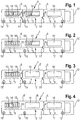
- Fig. 1 schematically illustrated sensor cartridge 1 is used in the recording of an analyzer, not shown, and has a continuous measuring channel 2 (shown in phantom), which serves to accommodate fluidic media, such as sample liquids, calibration quality control and washing media.
- Sensory elements 3, 4 for determining chemical and / or physical parameters of the fluidic media are arranged in the sensor cassette 1.
- the sensor cartridge 1 is according to Fig. 1 of three permanently interconnected externally substantially identically constructed modules 5, which each comprise measuring channel sections 9 in a housing 7, the measuring channel sections of adjacent modules being connected to the continuous measuring channel 2 by a fluidic coupling 11.
- each of the modules 5 is designed as a sensor module for different types of sensory elements, the first two modules being electrochemical sensors 3 and the last module 5 with the handle element 12, for example, optical sensors 4 has.
- the fluidic connections 15 of the two outer modules are designed as a sensor cassette-side inlet or outlet of the continuous measuring channel 2, which enable the fluidic connection to the analyzer for the purpose of introducing sample liquids and / or functional fluids.
- the fluidic connection 15 of the middle sensor module can serve here as a fluidic auxiliary or auxiliary connection (eg for supplying the reference electrolyte in the case of electrochemical measurement modules or for supplying reagents required for analyte determination).
- one of the two fluidic connections 15 of the module 6 is formed as a sensor cassette side input or output of the continuous measuring channel 2, while the other fluidic connection here as a fluidic auxiliary or auxiliary connection (eg for supplying the reference electrolyte in electrochemical measurement modules or to supply for analyte determination of required reagents) is formed.
- a module can also contain sensory elements which are based on different detection principles.
- the module shown on the left contains electrochemical sensory elements in its left-hand area and other sensory elements, for example optical sensory elements, in the right-hand area.
- the sensor cassette 1 has two sensor modules 5 and (in the middle) a dummy module 5 'which essentially corresponds to the sensor modules 5 except for the missing sensory elements.
- the fluidic connection 15 of the dummy module 5 ' is formed as an empty or blind connection.
- a module 6 ' which has a sensor array with sensory units 3 and a free area D which is free from sensory elements.
- This design realizes the same external dimensions even when the components are equipped with sensory elements.
- the dummy module 5 '( Fig. 3 ) or the free area D of the module 6 '( Fig. 4 ) may have a fluid port 15, which is designed as a vacant connection.
- the sensor modules 5, 6, 6 'and the dummy modules 5' of a sensor cassette 1 together have the dimensions and fluid connections 15 corresponding to the reception of the analyzer. The same applies to the electrical contact points 13 or other signal-taking regions within the windows 14.
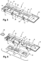
- a concrete embodiment of a modular sensor cassette 1 is shown, which consists of a single module 5 (with grip part 12 fixedly connected here) and a double module 6 with two fluid connections 15.
- a number of electrochemical sensor elements 3 are applied to a carrier part 16, which are connected to the contact points 13 via strip conductors. The electrical contacts are tapped by the analyzer through the window 14 of the modules 5, 6.
- the individual modules 5, 6 of the sensor cassette 1 are connected to each other by a fixed mechanical snap, for example by means of locking elements 17, with the interposition of a seal 18.
- the solid connection can also be made by welding or by gluing.
- a memory element 19 is arranged as a memory chip on which specific information for the sensor cartridge 1, in particular to the structure of the respective modules 5, 6, stored after insertion of the sensor cartridge 1 in the analyzer will be read out automatically.
- the carrier part 16 (for example, its rear side) can serve as a thermal contact zone, via which the individual modules 5, 6 can be thermostated in the analyzer to a different operating temperature. How out Fig. 6 recognizable, the thermal contact zones of adjacent modules 5, 6 of the Sensor cassette 1 thermally decoupled (eg by a corresponding distance of the support members 16 or by temperature-insulating materials).
- optical windows may be provided for transmission or reflection measurements.
- hemoglobin values can be determined by means of spectroscopic methods.
- the dummy modules 5 ' may also contain thermal contact zones for preheating or cooling sample and functional fluids in order to at least partially preheat these, for example, to an operating temperature necessary for subsequent sensor modules.
- tempering devices can also be located within the modules themselves, which are controlled accordingly, for example by appropriate electrical contacting of the analyzer.
- the sensors of a first module at body temperature e.g., blood gas sensors at 37 ° C
- the sensors of a second module may be operated at a lower temperature (e.g., metabolite or electrolyte sensors at 30 ° C).
- Individual modules of the sensor cassette can also have areas with fluidic elements or functionalities integrated in the fluid paths, which include, for example, valve functions or pump functions.
- the fluid flowing through the fluid paths is thereby acted upon by means of corresponding actuators.
- valves can be used through which the fluid paths are switched or closed.
- pumps for conveying the fluid can be integrated in individual modules. It is not absolutely necessary that all components of the fluidic elements or functionalities are contained in the module. Certain components of these fluidic elements or functionalities may also be arranged on the analyzer side and then engage in corresponding module-side sub-elements in order to be used in the module Interaction to create a fluidic effect.
- peristaltic pumps with analyzer-side rotor and module-side hose or shut-off valves with ram arranged on the analyzer side and corresponding module-side squeezable hose sections.
- the modular sensor cassette is assembled in the factory and packaged ready for use in suitable containers for the user.
- the modular sensor cassette 1 for the determination of blood values (see Fig. 5 and Fig. 6 ) is realized with two sensor modules 5, 6, which are inextricably linked at the factory by a snap connection.
- the first module 5 of the sensor cassette contains sensory elements for determining the blood gas parameters (pO 2 , pCO 2 ) the pH value and the hematocrit
- the second module 6 contains sensory elements for the determination of metabolite values (glucose, lactate,) and electrolyte concentrations ( Na + , K + , Ca 2+ , Cl - .).
- the sensor modules 5, 6 have different geometric dimensions in this example.
- sealing elements between the support members 16 and the corresponding upper housing parts of the respective modules are not shown explicitly in this figure. These sealing elements, in interaction with the respective carriers and upper housing parts, define the fluidic channels, in particular also the measuring channel, within the respective modules.
- the second module 6 is approximately twice as long as the first module 5 (less grip part 12). Both modules are operated at different temperatures (37 ° C and 30 ° C respectively).
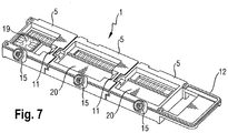
- the second module 6 of Example 1 can be replaced by two short modules 5 (see Fig. 7 ), one containing the electrolyte sensors and the other containing the metabolite sensors.
- the location and use of the fluidic connections 15 is shown here only schematically.
- the type and arrangement of the modules within the sensor cassette is not limited. So in addition to sensor modules and dummy modules in principle, further modules can be inserted, which can take over special functions.
- special sample input modules can be used, which have special devices (for example, connections for capillaries or syringes), by means of which the sample liquid to be examined can be introduced into the sensor cassette.
- special sample input and / or sample output modules can be used, which are arranged terminal in the sensor cassette and the transport of the sample liquid or other functional fluids to the centrally located within the sensor cartridge further modules out or away from this effect.
- Such special sample input and / or sample output modules can thus serve as universally usable fluidic contact points to the analyzer, which connect the sample channel of the sensor cassette with a corresponding fluidics in the analyzer, so that all other (internal) modules can in principle be equipped with the same dimensions and connections. whereby they can be combined in principle unlimited.
Applications Claiming Priority (2)
| Application Number | Priority Date | Filing Date | Title |
|---|---|---|---|
| US98744607P | 2007-11-13 | 2007-11-13 | |
| PCT/EP2008/065338 WO2009062940A1 (de) | 2007-11-13 | 2008-11-12 | Modulare sensorkassette |
Publications (2)
| Publication Number | Publication Date |
|---|---|
| EP2209554A1 EP2209554A1 (de) | 2010-07-28 |
| EP2209554B1 true EP2209554B1 (de) | 2017-10-11 |
Family
ID=40202903
Family Applications (1)
| Application Number | Title | Priority Date | Filing Date |
|---|---|---|---|
| EP08849867.0A Active EP2209554B1 (de) | 2007-11-13 | 2008-11-12 | Modulare sensorkassette |
Country Status (9)
| Country | Link |
|---|---|
| US (1) | US8262992B2 (ja) |
| EP (1) | EP2209554B1 (ja) |
| JP (1) | JP5383691B2 (ja) |
| CN (1) | CN101970112B (ja) |
| CA (1) | CA2705355C (ja) |
| DK (1) | DK2209554T3 (ja) |
| ES (1) | ES2654087T3 (ja) |
| HK (1) | HK1154222A1 (ja) |
| WO (1) | WO2009062940A1 (ja) |
Families Citing this family (36)
| Publication number | Priority date | Publication date | Assignee | Title |
|---|---|---|---|---|
| AU2005233571B2 (en) | 2004-04-07 | 2008-10-09 | Levine, Robert A. | Disposable chamber for analyzing biologic fluids |
| US7731901B2 (en) | 2005-10-19 | 2010-06-08 | Abbott Laboratories | Apparatus and method for performing counts within a biologic fluid sample |
| CN106110923A (zh) * | 2009-12-18 | 2016-11-16 | 艾博特健康公司 | 生物流体样本分析卡盒 |
| US9199233B2 (en) | 2010-03-31 | 2015-12-01 | Abbott Point Of Care, Inc. | Biologic fluid analysis cartridge with deflecting top panel |
| WO2011130629A1 (en) | 2010-04-16 | 2011-10-20 | Claros Diagnostics, Inc. | Systems and devices for analysis of samples |
| USD645971S1 (en) | 2010-05-11 | 2011-09-27 | Claros Diagnostics, Inc. | Sample cassette |
| EP2409766A1 (de) * | 2010-07-23 | 2012-01-25 | F. Hoffmann-La Roche AG | Verfahren zur Hydrophilisierung von Oberflächen fluidischer Komponenten und derartige Komponenten enthaltende Bauteile |
| WO2012092593A1 (en) | 2010-12-30 | 2012-07-05 | Abbott Point Of Care, Inc. | Biologic fluid analysis cartridge with sample handling portion and analysis chamber portion |
| CN105817276B (zh) * | 2011-08-24 | 2018-02-06 | 艾博特健康公司 | 生物流体样品分析盒 |
| US10012664B2 (en) * | 2011-09-25 | 2018-07-03 | Theranos Ip Company, Llc | Systems and methods for fluid and component handling |
| US9404668B2 (en) | 2011-10-06 | 2016-08-02 | Lennox Industries Inc. | Detecting and correcting enthalpy wheel failure modes |
| US9175872B2 (en) | 2011-10-06 | 2015-11-03 | Lennox Industries Inc. | ERV global pressure demand control ventilation mode |
| US9835353B2 (en) | 2011-10-17 | 2017-12-05 | Lennox Industries Inc. | Energy recovery ventilator unit with offset and overlapping enthalpy wheels |
| US20130095744A1 (en) * | 2011-10-17 | 2013-04-18 | Lennox Industries Inc. | Sensor mounting panel for an energy recovery ventilator unit |
| US9441843B2 (en) | 2011-10-17 | 2016-09-13 | Lennox Industries Inc. | Transition module for an energy recovery ventilator unit |
| US9395097B2 (en) | 2011-10-17 | 2016-07-19 | Lennox Industries Inc. | Layout for an energy recovery ventilator system |
| US20130118188A1 (en) | 2011-11-10 | 2013-05-16 | Justin McKie | Method of defrosting an energy recovery ventilator unit |
| US9671122B2 (en) | 2011-12-14 | 2017-06-06 | Lennox Industries Inc. | Controller employing feedback data for a multi-strike method of operating an HVAC system and monitoring components thereof and an HVAC system employing the controller |
| DE102012205171B3 (de) | 2012-03-29 | 2013-09-12 | Fraunhofer-Gesellschaft zur Förderung der angewandten Forschung e.V. | Integriertes Einweg-Chipkartuschensystem für mobile Multiparameteranalysen chemischer und/oder biologischer Substanzen |
| WO2016123185A2 (en) * | 2015-01-28 | 2016-08-04 | Opti Medicalsystems, Inc. | Cartridges, analyzers, and systems for analyzing samples |
| USD804682S1 (en) | 2015-08-10 | 2017-12-05 | Opko Diagnostics, Llc | Multi-layered sample cassette |
| CN108139418B (zh) * | 2015-10-09 | 2022-06-07 | 希森美康株式会社 | 受试体处理芯片、受试体处理装置及受试体处理方法 |
| CN107402310A (zh) * | 2016-05-19 | 2017-11-28 | 杭州凯珥医疗科技有限公司 | 一种用于体外诊断仪的具有识别功能的检测装置和方法 |
| USD802459S1 (en) | 2016-05-25 | 2017-11-14 | Agilent Technologies, Inc. | Fluid flow meter |
| US10480979B2 (en) | 2016-05-25 | 2019-11-19 | Agilent Technologies, Inc. | Flow meters, flow meter cartridges, and related methods |
| DE102016113041A1 (de) | 2016-07-15 | 2018-01-18 | B. Braun Melsungen Ag | Verfahren zum Austausch von Daten bei einem medizintechnischen Messsystem mit austauschbarem Einmalartikel |
| DE102016124059B4 (de) * | 2016-07-25 | 2019-12-19 | Leibniz-Institut Für Festkörper- Und Werkstoffforschung Dresden E.V. | Vorrichtung für die mikrofluidik |
| AT520605B1 (de) * | 2017-11-10 | 2020-03-15 | Erba Tech Austria Gmbh | Sensorkassette |
| FR3074911B1 (fr) | 2017-12-11 | 2022-05-27 | Vitea Eng S R L | Dispositif et procede d'analyse de compositions liquides, notamment d'echantillons de liquides d'origine biologique pour la determination notamment des electrolytes |
| CA3182539A1 (en) * | 2018-07-10 | 2020-01-16 | Precision Planting Llc | Agricultural sampling system and related methods |
| KR102294916B1 (ko) | 2018-07-28 | 2021-08-27 | 한국과학기술원 | 모듈형 유체 칩 및 이를 포함하는 유체 유동 시스템 |
| EP3778026A4 (en) * | 2018-07-28 | 2022-01-19 | Korea Advanced Institute Of Science And Technology | MODULAR FLUID CHIP AND FLUID FLOW SYSTEM COMPRISING THE SAME |
| WO2020167391A1 (en) * | 2019-02-11 | 2020-08-20 | Exxonmobil Research And Engineering Company | Processes and apparatus for the modular analysis of a fluid sample |
| EP3709024B1 (en) * | 2019-03-12 | 2023-12-27 | Radiometer Medical ApS | Apparatus for analyzing biological samples |
| KR102297259B1 (ko) * | 2019-08-01 | 2021-09-03 | 한국과학기술원 | 모듈형 미세 유체 장치 및 이의 제조 방법 |
| EP4016069A1 (en) | 2020-12-21 | 2022-06-22 | F. Hoffmann-La Roche AG | Sensor device and method of its use |
Citations (1)
| Publication number | Priority date | Publication date | Assignee | Title |
|---|---|---|---|---|
| US4654127A (en) * | 1984-04-11 | 1987-03-31 | Sentech Medical Corporation | Self-calibrating single-use sensing device for clinical chemistry and method of use |
Family Cites Families (27)
| Publication number | Priority date | Publication date | Assignee | Title |
|---|---|---|---|---|
| JPS58105065A (ja) * | 1981-12-17 | 1983-06-22 | Olympus Optical Co Ltd | 免疫学的凝集反応に基く分析装置 |
| US4849177A (en) * | 1987-05-08 | 1989-07-18 | Abbott Laboratories | Reagent pack and carousel |
| US4975647A (en) | 1987-06-01 | 1990-12-04 | Nova Biomedical Corporation | Controlling machine operation with respect to consumable accessory units |
| AT392361B (de) * | 1987-06-30 | 1991-03-25 | Avl Verbrennungskraft Messtech | Analysegeraet und modul fuer ein analysegeraet |
| AT399228B (de) | 1990-06-08 | 1995-04-25 | Avl Verbrennungskraft Messtech | Verfahren zur analyse von gasförmigen oder flüssigen proben und einweg-messelement zur ausübung des verfahrens |
| EP0610325B1 (en) * | 1991-11-01 | 1997-05-07 | The University Of Birmingham | Assay device |
| JP2541081B2 (ja) | 1992-08-28 | 1996-10-09 | 日本電気株式会社 | バイオセンサ及びバイオセンサの製造・使用方法 |
| US5690893A (en) | 1994-06-10 | 1997-11-25 | Hitachi, Ltd. | Analyzer having sensor with memory device |
| JP3332664B2 (ja) | 1994-06-10 | 2002-10-07 | 株式会社日立製作所 | 分析装置及び要素パッケージ |
| AT403962B (de) | 1996-10-30 | 1998-07-27 | Avl Verbrennungskraft Messtech | Vorrichtung zur durchführung von elektrochemischen und/oder optischen messvorgängen in flüssigkeiten |
| US6066243A (en) | 1997-07-22 | 2000-05-23 | Diametrics Medical, Inc. | Portable immediate response medical analyzer having multiple testing modules |
| JP2002538457A (ja) | 1999-03-03 | 2002-11-12 | サイラノ・サイエンスィズ・インコーポレーテッド | 知覚データを検出しコンピュータネットワークで伝送する装置、システム、および方法 |
| DE19917330B4 (de) | 1999-04-16 | 2004-08-26 | INSTITUT FüR MIKROTECHNIK MAINZ GMBH | Mikroreaktormodul |
| WO2000070350A1 (en) | 1999-05-12 | 2000-11-23 | Cme Telemetrix Inc. | METHOD AND APPARATUS FOR RAPID MEASUREMENT OF HbA¿1c? |
| AT406912B (de) | 1999-05-20 | 2000-10-25 | Avl List Gmbh | Optische messanordnung zur bestimmung der transmissions- und streustrahlung |
| JP2003502661A (ja) | 1999-06-17 | 2003-01-21 | サイラノ・サイエンスィズ・インコーポレーテッド | 多重検出システムおよび装置 |
| ATA161499A (de) | 1999-09-21 | 2003-04-15 | Hoffmann La Roche | Elektrochemische messvorrichtung mit planarem sensorträger |
| AT410600B (de) | 1999-12-02 | 2003-06-25 | Hoffmann La Roche | Messkammer mit lumineszenzoptischen sensorelementen |
| US6960466B2 (en) | 2001-05-31 | 2005-11-01 | Instrumentation Laboratory Company | Composite membrane containing a cross-linked enzyme matrix for a biosensor |
| US6896778B2 (en) | 2001-06-04 | 2005-05-24 | Epocal Inc. | Electrode module |
| US7171312B2 (en) | 2002-07-19 | 2007-01-30 | Smiths Detection, Inc. | Chemical and biological agent sensor array detectors |
| DE10305050A1 (de) | 2003-02-07 | 2004-08-19 | Roche Diagnostics Gmbh | Analytisches Testelement und Verfahren für Blutuntersuchungen |
| DE102005052752A1 (de) | 2005-11-04 | 2007-05-10 | Clondiag Chip Technologies Gmbh | Vorrichtung und Verfahren zum Nachweis von molekularen Wechselwirkungen |
| DE102004022263A1 (de) * | 2004-05-06 | 2005-12-15 | Clondiag Chip Technologies Gmbh | Vorrichtung und Verfahren zum Nachweis von molekularen Wechselwirkungen |
| JP5004444B2 (ja) * | 2005-07-28 | 2012-08-22 | 東レエンジニアリング株式会社 | マイクロリアクタ |
| EP1752755B1 (de) * | 2005-08-10 | 2015-05-06 | Roche Diagnostics GmbH | Probenaufnahme- und-dosiervorrichtung mit integrierten Flüssigkeitskompartimenten |
| JP2009543041A (ja) * | 2006-06-28 | 2009-12-03 | コーニンクレッカ フィリップス エレクトロニクス エヌ ヴィ | 使い捨て分析装置及び分析方法 |
-
2008
- 2008-11-12 EP EP08849867.0A patent/EP2209554B1/de active Active
- 2008-11-12 DK DK08849867.0T patent/DK2209554T3/en active
- 2008-11-12 US US12/269,280 patent/US8262992B2/en active Active
- 2008-11-12 WO PCT/EP2008/065338 patent/WO2009062940A1/de active Application Filing
- 2008-11-12 CN CN200880116587.5A patent/CN101970112B/zh active Active
- 2008-11-12 CA CA2705355A patent/CA2705355C/en not_active Expired - Fee Related
- 2008-11-12 ES ES08849867.0T patent/ES2654087T3/es active Active
- 2008-11-12 JP JP2010532616A patent/JP5383691B2/ja active Active
-
2011
- 2011-08-04 HK HK11108125.8A patent/HK1154222A1/xx not_active IP Right Cessation
Patent Citations (1)
| Publication number | Priority date | Publication date | Assignee | Title |
|---|---|---|---|---|
| US4654127A (en) * | 1984-04-11 | 1987-03-31 | Sentech Medical Corporation | Self-calibrating single-use sensing device for clinical chemistry and method of use |
Also Published As
| Publication number | Publication date |
|---|---|
| JP2011502605A (ja) | 2011-01-27 |
| US8262992B2 (en) | 2012-09-11 |
| HK1154222A1 (en) | 2012-04-13 |
| EP2209554A1 (de) | 2010-07-28 |
| JP5383691B2 (ja) | 2014-01-08 |
| CA2705355C (en) | 2013-02-26 |
| CA2705355A1 (en) | 2009-05-22 |
| ES2654087T3 (es) | 2018-02-12 |
| CN101970112A (zh) | 2011-02-09 |
| CN101970112B (zh) | 2014-05-07 |
| US20090156966A1 (en) | 2009-06-18 |
| WO2009062940A1 (de) | 2009-05-22 |
| DK2209554T3 (en) | 2018-01-15 |
Similar Documents
| Publication | Publication Date | Title |
|---|---|---|
| EP2209554B1 (de) | Modulare sensorkassette | |
| EP2830763B1 (de) | Integriertes einweg-chipkartuschensystem für mobile multiparameteranalysen chemischer und/oder biologischer substanzen | |
| DE10111457B4 (de) | Diagnoseeinrichtung | |
| US9770716B2 (en) | Multi-fluidic cartridges for sample analysis and methods for using same | |
| DE60035111T2 (de) | Mikrofluidische systeme mit indizierungskomponenten | |
| US8747747B2 (en) | Reader devices for manipulating multi-fluidic cartridges for sample analysis | |
| EP1752755B1 (de) | Probenaufnahme- und-dosiervorrichtung mit integrierten Flüssigkeitskompartimenten | |
| DE69922207T2 (de) | Tragbare medizinische analysevorrichtung mit unmittelbarem respons | |
| DE19546535C2 (de) | Meßkartusche für flüssige oder gasförmige Proben, Verfahren zu deren Betreiben und deren Verwendung | |
| WO2007053870A2 (de) | Photometrisches messverfahren für eine probenflüssigkeit, photometrische messeinrichtung und mischbehälter für eine photometrische messeinrichtung | |
| US20020045243A1 (en) | Fluid cartridge and method | |
| DE102007044889B4 (de) | Diagnosetestsystem | |
| EP2217376B1 (de) | Küvette und verfahren zur verwendung der küvette | |
| DE102006024149B4 (de) | System zur integrierten und automatisierten DNA- oder Protein-Analyse | |
| DE102007019695A1 (de) | Küvette für die optische Analyse kleiner Volumina | |
| EP3710164B1 (de) | Sensorkassette | |
| DE19545130A1 (de) | Verfahren und Vorrichtungen für ein modulares Mikrosystem für hochgenaue chemische Schnell-Analysen und Verfahren zur Herstellung | |
| DE10306018A1 (de) | Analyse- und Diagnostikinstrument | |
| EP3609617B1 (de) | Vorrichtung zur prozessierung einer flüssigen probe | |
| EP3347691B1 (de) | Anordnung für die individualisierte patientenblutanalyse und verwendung | |
| DE10150269B4 (de) | Mikrokammer zur nicht-invasiven Messung an biologischem Material | |
| EP1510254A2 (de) | Verfahren und Vorrichtung zur Bestimmung von Analyten in einer Flüssigkeit | |
| DE10203211A1 (de) | Mikrofluidikprobenmodul mit Mitteln zur Temperaturbeeinflussung |
Legal Events
| Date | Code | Title | Description |
|---|---|---|---|
| PUAI | Public reference made under article 153(3) epc to a published international application that has entered the european phase |
Free format text: ORIGINAL CODE: 0009012 |
|
| 17P | Request for examination filed |
Effective date: 20100412 |
|
| AK | Designated contracting states |
Kind code of ref document: A1 Designated state(s): AT BE BG CH CY CZ DE DK EE ES FI FR GB GR HR HU IE IS IT LI LT LU LV MC MT NL NO PL PT RO SE SI SK TR |
|
| AX | Request for extension of the european patent |
Extension state: AL BA MK RS |
|
| RIN1 | Information on inventor provided before grant (corrected) |
Inventor name: OFFENBACHER, HELMUT Inventor name: SCHAFFAR, BERNHARD Inventor name: SCHINNERL, MARIE-LUISE Inventor name: HARER, JOHANN Inventor name: HUBER, WOLFGANG Inventor name: LEINER, MARCO JEAN-PIERRE Inventor name: KONTSCHIEDER, HEINZ Inventor name: KRYSL, FRANZ JOSEF Inventor name: RITTER, CHRISTOPH |
|
| DAX | Request for extension of the european patent (deleted) | ||
| RAP1 | Party data changed (applicant data changed or rights of an application transferred) |
Owner name: F. HOFFMANN-LA ROCHE AG Owner name: ROCHE DIAGNOSTICS GMBH |
|
| 17Q | First examination report despatched |
Effective date: 20110714 |
|
| APBK | Appeal reference recorded |
Free format text: ORIGINAL CODE: EPIDOSNREFNE |
|
| APBN | Date of receipt of notice of appeal recorded |
Free format text: ORIGINAL CODE: EPIDOSNNOA2E |
|
| APBR | Date of receipt of statement of grounds of appeal recorded |
Free format text: ORIGINAL CODE: EPIDOSNNOA3E |
|
| APBV | Interlocutory revision of appeal recorded |
Free format text: ORIGINAL CODE: EPIDOSNIRAPE |
|
| GRAP | Despatch of communication of intention to grant a patent |
Free format text: ORIGINAL CODE: EPIDOSNIGR1 |
|
| INTG | Intention to grant announced |
Effective date: 20170531 |
|
| RIN1 | Information on inventor provided before grant (corrected) |
Inventor name: HARER, JOHANN Inventor name: KONTSCHIEDER, HEINZ Inventor name: OFFENBACHER, HELMUT Inventor name: KRYSL, FRANZ JOSEF Inventor name: SCHAFFAR, BERNHARD Inventor name: RITTER, CHRISTOPH Inventor name: HUBER, WOLFGANG Inventor name: LEINER, MARCO JEAN-PIERRE Inventor name: SCHINNERL, MARIE-LUISE |
|
| GRAS | Grant fee paid |
Free format text: ORIGINAL CODE: EPIDOSNIGR3 |
|
| GRAA | (expected) grant |
Free format text: ORIGINAL CODE: 0009210 |
|
| AK | Designated contracting states |
Kind code of ref document: B1 Designated state(s): AT BE BG CH CY CZ DE DK EE ES FI FR GB GR HR HU IE IS IT LI LT LU LV MC MT NL NO PL PT RO SE SI SK TR |
|
| REG | Reference to a national code |
Ref country code: GB Ref legal event code: FG4D Free format text: NOT ENGLISH |
|
| REG | Reference to a national code |
Ref country code: CH Ref legal event code: EP |
|
| REG | Reference to a national code |
Ref country code: FR Ref legal event code: PLFP Year of fee payment: 10 |
|
| REG | Reference to a national code |
Ref country code: IE Ref legal event code: FG4D Free format text: LANGUAGE OF EP DOCUMENT: GERMAN |
|
| REG | Reference to a national code |
Ref country code: AT Ref legal event code: REF Ref document number: 935552 Country of ref document: AT Kind code of ref document: T Effective date: 20171115 |
|
| REG | Reference to a national code |
Ref country code: DE Ref legal event code: R096 Ref document number: 502008015671 Country of ref document: DE |
|
| REG | Reference to a national code |
Ref country code: DK Ref legal event code: T3 Effective date: 20180109 |
|
| REG | Reference to a national code |
Ref country code: ES Ref legal event code: FG2A Ref document number: 2654087 Country of ref document: ES Kind code of ref document: T3 Effective date: 20180212 |
|
| REG | Reference to a national code |
Ref country code: NL Ref legal event code: MP Effective date: 20171011 |
|
| REG | Reference to a national code |
Ref country code: LT Ref legal event code: MG4D |
|
| PG25 | Lapsed in a contracting state [announced via postgrant information from national office to epo] |
Ref country code: NL Free format text: LAPSE BECAUSE OF FAILURE TO SUBMIT A TRANSLATION OF THE DESCRIPTION OR TO PAY THE FEE WITHIN THE PRESCRIBED TIME-LIMIT Effective date: 20171011 |
|
| PG25 | Lapsed in a contracting state [announced via postgrant information from national office to epo] |
Ref country code: FI Free format text: LAPSE BECAUSE OF FAILURE TO SUBMIT A TRANSLATION OF THE DESCRIPTION OR TO PAY THE FEE WITHIN THE PRESCRIBED TIME-LIMIT Effective date: 20171011 Ref country code: LT Free format text: LAPSE BECAUSE OF FAILURE TO SUBMIT A TRANSLATION OF THE DESCRIPTION OR TO PAY THE FEE WITHIN THE PRESCRIBED TIME-LIMIT Effective date: 20171011 Ref country code: SE Free format text: LAPSE BECAUSE OF FAILURE TO SUBMIT A TRANSLATION OF THE DESCRIPTION OR TO PAY THE FEE WITHIN THE PRESCRIBED TIME-LIMIT Effective date: 20171011 Ref country code: NO Free format text: LAPSE BECAUSE OF FAILURE TO SUBMIT A TRANSLATION OF THE DESCRIPTION OR TO PAY THE FEE WITHIN THE PRESCRIBED TIME-LIMIT Effective date: 20180111 |
|
| PG25 | Lapsed in a contracting state [announced via postgrant information from national office to epo] |
Ref country code: BG Free format text: LAPSE BECAUSE OF FAILURE TO SUBMIT A TRANSLATION OF THE DESCRIPTION OR TO PAY THE FEE WITHIN THE PRESCRIBED TIME-LIMIT Effective date: 20180111 Ref country code: LV Free format text: LAPSE BECAUSE OF FAILURE TO SUBMIT A TRANSLATION OF THE DESCRIPTION OR TO PAY THE FEE WITHIN THE PRESCRIBED TIME-LIMIT Effective date: 20171011 Ref country code: HR Free format text: LAPSE BECAUSE OF FAILURE TO SUBMIT A TRANSLATION OF THE DESCRIPTION OR TO PAY THE FEE WITHIN THE PRESCRIBED TIME-LIMIT Effective date: 20171011 Ref country code: IS Free format text: LAPSE BECAUSE OF FAILURE TO SUBMIT A TRANSLATION OF THE DESCRIPTION OR TO PAY THE FEE WITHIN THE PRESCRIBED TIME-LIMIT Effective date: 20180211 Ref country code: GR Free format text: LAPSE BECAUSE OF FAILURE TO SUBMIT A TRANSLATION OF THE DESCRIPTION OR TO PAY THE FEE WITHIN THE PRESCRIBED TIME-LIMIT Effective date: 20180112 |
|
| REG | Reference to a national code |
Ref country code: DE Ref legal event code: R097 Ref document number: 502008015671 Country of ref document: DE |
|
| PG25 | Lapsed in a contracting state [announced via postgrant information from national office to epo] |
Ref country code: EE Free format text: LAPSE BECAUSE OF FAILURE TO SUBMIT A TRANSLATION OF THE DESCRIPTION OR TO PAY THE FEE WITHIN THE PRESCRIBED TIME-LIMIT Effective date: 20171011 Ref country code: SK Free format text: LAPSE BECAUSE OF FAILURE TO SUBMIT A TRANSLATION OF THE DESCRIPTION OR TO PAY THE FEE WITHIN THE PRESCRIBED TIME-LIMIT Effective date: 20171011 Ref country code: MC Free format text: LAPSE BECAUSE OF FAILURE TO SUBMIT A TRANSLATION OF THE DESCRIPTION OR TO PAY THE FEE WITHIN THE PRESCRIBED TIME-LIMIT Effective date: 20171011 Ref country code: CZ Free format text: LAPSE BECAUSE OF FAILURE TO SUBMIT A TRANSLATION OF THE DESCRIPTION OR TO PAY THE FEE WITHIN THE PRESCRIBED TIME-LIMIT Effective date: 20171011 |
|
| PLBE | No opposition filed within time limit |
Free format text: ORIGINAL CODE: 0009261 |
|
| STAA | Information on the status of an ep patent application or granted ep patent |
Free format text: STATUS: NO OPPOSITION FILED WITHIN TIME LIMIT |
|
| PG25 | Lapsed in a contracting state [announced via postgrant information from national office to epo] |
Ref country code: PL Free format text: LAPSE BECAUSE OF FAILURE TO SUBMIT A TRANSLATION OF THE DESCRIPTION OR TO PAY THE FEE WITHIN THE PRESCRIBED TIME-LIMIT Effective date: 20171011 Ref country code: RO Free format text: LAPSE BECAUSE OF FAILURE TO SUBMIT A TRANSLATION OF THE DESCRIPTION OR TO PAY THE FEE WITHIN THE PRESCRIBED TIME-LIMIT Effective date: 20171011 Ref country code: LU Free format text: LAPSE BECAUSE OF NON-PAYMENT OF DUE FEES Effective date: 20171112 |
|
| REG | Reference to a national code |
Ref country code: BE Ref legal event code: MM Effective date: 20171130 |
|
| REG | Reference to a national code |
Ref country code: IE Ref legal event code: MM4A |
|
| 26N | No opposition filed |
Effective date: 20180712 |
|
| PG25 | Lapsed in a contracting state [announced via postgrant information from national office to epo] |
Ref country code: MT Free format text: LAPSE BECAUSE OF FAILURE TO SUBMIT A TRANSLATION OF THE DESCRIPTION OR TO PAY THE FEE WITHIN THE PRESCRIBED TIME-LIMIT Effective date: 20171011 |
|
| REG | Reference to a national code |
Ref country code: FR Ref legal event code: PLFP Year of fee payment: 11 |
|
| PG25 | Lapsed in a contracting state [announced via postgrant information from national office to epo] |
Ref country code: IE Free format text: LAPSE BECAUSE OF NON-PAYMENT OF DUE FEES Effective date: 20171112 |
|
| PG25 | Lapsed in a contracting state [announced via postgrant information from national office to epo] |
Ref country code: BE Free format text: LAPSE BECAUSE OF NON-PAYMENT OF DUE FEES Effective date: 20171130 Ref country code: SI Free format text: LAPSE BECAUSE OF FAILURE TO SUBMIT A TRANSLATION OF THE DESCRIPTION OR TO PAY THE FEE WITHIN THE PRESCRIBED TIME-LIMIT Effective date: 20171011 |
|
| REG | Reference to a national code |
Ref country code: AT Ref legal event code: MM01 Ref document number: 935552 Country of ref document: AT Kind code of ref document: T Effective date: 20171112 |
|
| PG25 | Lapsed in a contracting state [announced via postgrant information from national office to epo] |
Ref country code: AT Free format text: LAPSE BECAUSE OF NON-PAYMENT OF DUE FEES Effective date: 20171112 |
|
| PG25 | Lapsed in a contracting state [announced via postgrant information from national office to epo] |
Ref country code: HU Free format text: LAPSE BECAUSE OF FAILURE TO SUBMIT A TRANSLATION OF THE DESCRIPTION OR TO PAY THE FEE WITHIN THE PRESCRIBED TIME-LIMIT; INVALID AB INITIO Effective date: 20081112 |
|
| PG25 | Lapsed in a contracting state [announced via postgrant information from national office to epo] |
Ref country code: CY Free format text: LAPSE BECAUSE OF NON-PAYMENT OF DUE FEES Effective date: 20171011 |
|
| PG25 | Lapsed in a contracting state [announced via postgrant information from national office to epo] |
Ref country code: TR Free format text: LAPSE BECAUSE OF FAILURE TO SUBMIT A TRANSLATION OF THE DESCRIPTION OR TO PAY THE FEE WITHIN THE PRESCRIBED TIME-LIMIT Effective date: 20171011 |
|
| PG25 | Lapsed in a contracting state [announced via postgrant information from national office to epo] |
Ref country code: PT Free format text: LAPSE BECAUSE OF FAILURE TO SUBMIT A TRANSLATION OF THE DESCRIPTION OR TO PAY THE FEE WITHIN THE PRESCRIBED TIME-LIMIT Effective date: 20171011 |
|
| PGFP | Annual fee paid to national office [announced via postgrant information from national office to epo] |
Ref country code: GB Payment date: 20231019 Year of fee payment: 16 |
|
| PGFP | Annual fee paid to national office [announced via postgrant information from national office to epo] |
Ref country code: ES Payment date: 20231201 Year of fee payment: 16 |
|
| PGFP | Annual fee paid to national office [announced via postgrant information from national office to epo] |
Ref country code: IT Payment date: 20231019 Year of fee payment: 16 Ref country code: FR Payment date: 20231019 Year of fee payment: 16 Ref country code: DK Payment date: 20231019 Year of fee payment: 16 Ref country code: DE Payment date: 20231019 Year of fee payment: 16 Ref country code: CH Payment date: 20231201 Year of fee payment: 16 |