EP2208563A1 - Kopfstück und werkzeughauptelement für ein schneidewerkzeug mit abnehmbarem einsatz und schneidewerkzeug mit abnehmbarem einsatz - Google Patents
Kopfstück und werkzeughauptelement für ein schneidewerkzeug mit abnehmbarem einsatz und schneidewerkzeug mit abnehmbarem einsatz Download PDFInfo
- Publication number
- EP2208563A1 EP2208563A1 EP08845496A EP08845496A EP2208563A1 EP 2208563 A1 EP2208563 A1 EP 2208563A1 EP 08845496 A EP08845496 A EP 08845496A EP 08845496 A EP08845496 A EP 08845496A EP 2208563 A1 EP2208563 A1 EP 2208563A1
- Authority
- EP
- European Patent Office
- Prior art keywords
- head member
- rear end
- insert
- jaw portion
- slit
- Prior art date
- Legal status (The legal status is an assumption and is not a legal conclusion. Google has not performed a legal analysis and makes no representation as to the accuracy of the status listed.)
- Granted
Links
Images


Classifications
-
- B—PERFORMING OPERATIONS; TRANSPORTING
- B23—MACHINE TOOLS; METAL-WORKING NOT OTHERWISE PROVIDED FOR
- B23B—TURNING; BORING
- B23B29/00—Holders for non-rotary cutting tools; Boring bars or boring heads; Accessories for tool holders
- B23B29/04—Tool holders for a single cutting tool
- B23B29/043—Tool holders for a single cutting tool with cutting-off, grooving or profile cutting tools, i.e. blade- or disc-like main cutting parts
-
- B—PERFORMING OPERATIONS; TRANSPORTING
- B23—MACHINE TOOLS; METAL-WORKING NOT OTHERWISE PROVIDED FOR
- B23B—TURNING; BORING
- B23B27/00—Tools for turning or boring machines; Tools of a similar kind in general; Accessories therefor
- B23B27/04—Cutting-off tools
-
- B—PERFORMING OPERATIONS; TRANSPORTING
- B23—MACHINE TOOLS; METAL-WORKING NOT OTHERWISE PROVIDED FOR
- B23B—TURNING; BORING
- B23B2205/00—Fixation of cutting inserts in holders
- B23B2205/02—Fixation using an elastically deformable clamping member
-
- Y—GENERAL TAGGING OF NEW TECHNOLOGICAL DEVELOPMENTS; GENERAL TAGGING OF CROSS-SECTIONAL TECHNOLOGIES SPANNING OVER SEVERAL SECTIONS OF THE IPC; TECHNICAL SUBJECTS COVERED BY FORMER USPC CROSS-REFERENCE ART COLLECTIONS [XRACs] AND DIGESTS
- Y10—TECHNICAL SUBJECTS COVERED BY FORMER USPC
- Y10T—TECHNICAL SUBJECTS COVERED BY FORMER US CLASSIFICATION
- Y10T407/00—Cutters, for shaping
- Y10T407/22—Cutters, for shaping including holder having seat for inserted tool
- Y10T407/227—Cutters, for shaping including holder having seat for inserted tool with separate means to fasten tool seat to holder
-
- Y—GENERAL TAGGING OF NEW TECHNOLOGICAL DEVELOPMENTS; GENERAL TAGGING OF CROSS-SECTIONAL TECHNOLOGIES SPANNING OVER SEVERAL SECTIONS OF THE IPC; TECHNICAL SUBJECTS COVERED BY FORMER USPC CROSS-REFERENCE ART COLLECTIONS [XRACs] AND DIGESTS
- Y10—TECHNICAL SUBJECTS COVERED BY FORMER USPC
- Y10T—TECHNICAL SUBJECTS COVERED BY FORMER US CLASSIFICATION
- Y10T407/00—Cutters, for shaping
- Y10T407/22—Cutters, for shaping including holder having seat for inserted tool
- Y10T407/2272—Cutters, for shaping including holder having seat for inserted tool with separate means to fasten tool to holder
- Y10T407/2282—Cutters, for shaping including holder having seat for inserted tool with separate means to fasten tool to holder including tool holding clamp and clamp actuator
- Y10T407/2286—Resiliently biased clamp jaw
- Y10T407/2288—Integral with holder
Definitions
- the present invention relates to a head member of a cutting tool with detachable insert which is formed with an insert attachment seat to which a cutting insert having cutting blades is detachably attached and which constitutes the insert detachable cutting tool by being mounted on a tip portion of a holder, a tool body on which the head member is mounted on the tip portion of the holder, and a cutting tool with detachable insert which is used for, for example, grooving or cutting-off of a work material and in which an insert is clamped by the head member attached to the tip portion of the holder.
- Priority is claimed on Japanese Patent Application No. 2007-282118, filed October 30, 2007 , the content of which is incorporated herein by reference.
- a tool with detachable insert used for grooving or cutting-off of a work material there is a tool having the following structure.
- a pressing surface is provided in one jaw portion of a pair of jaw portions formed at the tip of a holder.
- a pedestal surface is provided in the other jaw portion of the pair of jaw portions.
- the pressing surfaces and a pedestal surface are arranged so as to face each other.
- An insert attachment seat is formed in this way. Additionally from a rear end of the insert attachment seat, a slit is provided so as to further extend towards the rear end of the tool.
- a cutting insert which has cutting blades is clamped and attached between the pressing surface and the pedestal surface by screwing in the clamp screw engaged with one jaw portion, and elastically deforming one jaw portion.
- Patent Document 1 Japanese Patent Unexamined Publication No. 05-192802
- the clamp screw be made to engage one jaw portion at a position as close to the insert attachment seat as possible in the extension direction of the slit or a direction towards the rear end side from the tip side. In this way, it is desirable that the clamping force is made to act directly on the clamp of the cutting insert as much as possible.
- the width of the pair of jaw portions is limited, especially in the cutting tool with detachable insert used for grooving or cutting-off.
- the diameter of the clamp screw should be made small, and there is a possibility that a sufficient clamping force cannot be obtained.
- a clamp screw engaged with the one jaw portion in this way should be screwed into the holder while inclining in a separate direction as it moves towards the other jaw portion, with respect to an imaginary plane which extends in a direction in which the pressing surface and the pedestal surface face each other along an extension direction of the slit.
- the large-diameter clamp screw can be engaged with one jaw portion near the insert attachment seat, irrespective of the width of the jaw portions, or the size of the head member.
- the present invention was made taking the above into consideration, and the object of the present invention is to provide a head member for a cutting tool with detachable insert capable of clamping a cutting insert stably by elastically deforming one jaw portion formed with a pressing surface straight with respect to a pedestal surface, while a large clamping force is made to act on a cutting insert especially in the head member of an insert detachable cutting tool used for grooving or cutting-off, a tool body in which the head member is mounted on a tip portion of a holder, and a cutting tool with detachable insert in which an insert is clamped by the head member attached to the tip portion of the holder.
- the present invention relates to a head member for a cutting tool with detachable insert
- a head member body formed with an insert attachment seat to which a cutting insert having cutting blades is detachably attached, and constituting the cutting tool by being mounted to a tip portion of a holder.
- the insert attachment seat is formed by a pressing surface of one jaw portion and a pedestal surface of the other jaw portion in a pair of jaw portions formed in the head member body so as to be opened towards the tip side and extend towards a rear end side of the head member body. Additionally, from a rear end of the insert attachment seat, a slit is provided so as to further extend towards the rear end side.
- a clamp screw engaged with the one jaw portion is screwed into the holder while inclining in a direction separated as it moves towards the other jaw portion, with respect to an imaginary plane which extends along an extension direction of the slit and in a direction in which the pressing surface and the pedestal surface face each other, whereby the one jaw portion is enabled to elastically deform towards the other jaw portion by using as a fulcrum a connecting portion of the pair of jaw portions formed between the rear wall surface of the slit which faces the tip side, and the rear end surface of the head member body located on the extension direction of the rear wall surface.
- the connecting portion is formed such that the width thereof in the extension direction becomes gradually greater as the clamp screw moves in the direction separated from the imaginary plane.
- the present invention relates also to a tool body to which such a head member is mounted on the tip portion of the holder, and an cutting tool with detachable insert used in which an insert is clamped by the head member attached to the tip portion of the holder.
- a clamp screw engaged with the one jaw portion is screwed into the holder while inclining in a direction separated as it moves towards the other jaw portion, with respect to an imaginary plane which extends in a direction in which the pressing surface and the pedestal surface face each other along an extension direction of the slit. Therefore, by using a large-diameter clamp screw, and engaging the clamp screw with one jaw portion at a position closer to the insert attachment seat irrespective of the width of the jaw portions, the size of the head member body, etc., one jaw portion can be made to elastically deform, and a large clamping force can be made to act on a cutting insert.
- the connecting portion between the rear wall surface of the slit and the rear end surface of the head member body, which becomes a fulcrum of this elastic deformation, is formed so that the clamp screw screwed in while inclining to the imaginary plane becomes gradually wider in the direction separated from the imaginary plane towards the screwing direction. That is, since the connecting portion becomes thick-walled on the side of the separating direction, one jaw portion hardly deforms on the side of the separating direction. For this reason, it is possible to restrain one jaw portion to be elastically deformed as it inclined accompany the clamp screw to be screwed in as it inclined. As a result, it is possible to make the pressing surface of the one jaw portion approach the pedestal surface straight along the imaginary plane, and clamp a cutting insert reliably and stably by the above-described large clamping force.
- the connecting portion become gradually wider so that the rear wall surface and the rear end surface intersect each other within a range of 5° to 15° in a cross-section along the extension direction of the slit in the rear wall surface.
- a head member is mounted on the holder, for example, by screwing the fixing screw inserted through the head member body into the tip portion of the holder.
- the head member body mounted on the tip portion of the holder with a limited size is formed with an insertion hole through which the fixing screw is inserted, since the insertion hole and the slit will interfere with each other, the length of the slit may be limited.
- a rear end portion of the slit may be formed with a bent portion which is provided so as to extend towards the rear end side while being bent towards the one jaw portion, thereby extend and provide the slit so as to avoid the interference with the insertion hole.
- the connecting portion which becomes a fulcrum of elastic deformation can be located closer to the rear end side, even if one jaw portion along the imaginary plane has elastically deformed, the cutting insert can be reliably pressed by making the inclination of the pressing surface as small as possible, and higher clamp stability can be secured.
- a large clamping force can be made to act on the cutting insert by using a larger-diameter clamp screw, irrespective of the width of the jaw portions or the size of the head member body.
- the clamp screw is screwed into the holder as it inclined, the one jaw portion formed with the pressing surface can be elastically deformed straight with respect to the pedestal surface without inclining. As a result, it is possible to clamp the cutting insert stably and firmly and to improve machining accuracy.
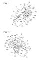
- FIGS. 1 to 12 show one embodiment of a head member of the present invention
- FIGS. 13 to 16 show one embodiment for a cutting tool with detachable insert of the present invention on which the head member of the present embodiment is mounted.
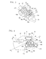
- the cutting tool with detachable insert 70 of the present embodiment is a turning tool (cutting tool) with detachable insert which performs grooving or cutting-off on a rotating work material, and includes a substantially quadrangular prismatic holder 10 which is held by a tool rest of a machine tool, a head member 30 of the above embodiment which is mounted on the tip of the holder 10, and a cutting insert 50 which is clamped by the head member 30. Additionally, a tool body 60 is formed from the holder 10, and the head member 30 which is mounted at a tip portion of the holder 10.
- the holder 10 is formed of steel and has a substantially square prismatic shape having an upper surface 11 and a lower surface 12 which face each other, and a pair of side surfaces 13A and 13B, and the rear end side (the upper right side in FIGS. 13 and 15 and the upper left side in FIGS. 14 and 16 ) of the holder is formed as a shank portion 14 which extends along an axis O of the square prism. Additionally, the tip side (the lower left side in FIGS. 13 and 15 , and the lower right side in FIGS.
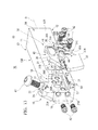
- the holder 10 is formed with a protruding portion 15 which protrudes towards the upside from the upper surface 11 of the holder 10, and the tip portion of the holder 10 formed with the protruding portion 15 is provided with a mounting portion 16 for mounting the head member 30.
- the mounting portion 16 is formed in a recessed shape so that the tip surface of the holder 10 and the part of the tip portion on the side of one side surface 13A are cut out. Additionally, the mounting portion 16 includes a first receiving surface 17 which has a planar shape which extends parallel to the one side surface 13A of the holder 10, a second receiving surface 18 which has a planar shape which extends in a direction orthogonal to the first receiving surface 17 and is orthogonal to the axis O and which faces the tip side of the holder 10, and a third receiving surface 19 which has an upward planar shape which extends in a direction orthogonal to the first and second receiving surfaces 17 and 18.
- the first receiving surface 17 is formed so as to be recessed from the one side surface 13A towards the other side surface 13B and extend up to the upper end of the protruding portion 15. Also, in the first receiving surface 17, three first fixing screw holes 20A to 20C are bored in the direction orthogonal to the first receiving surface 17 in the present embodiment.
- the first fixing screw holes 20A to 20C are formed so as to be lined up with each other in the direction of the axis O or be lined up in the front-back direction of the holder 10, and so as to open at the positions of respective apexes of a scalene triangle which is flat up and down and becomes upwardly convex as shown in FIG. 13 .
- the second receiving surface 18 is arranged on the tip side in the direction of the axis O of the first receiving surface 17 in the orthogonal direction via a chamfered portion, and is formed so as to be recessed further towards the rear end side than the tip surface of the protruding portion 15, and have an L-shape as seen from the tip side.
- Two second fixing screw holes 21A and 21B bored in a direction orthogonal to the second receiving surface 18 are also opened in the second receiving surface 18 so as to be lined up in a direction which extends parallel to the first receiving surface 17 and orthogonal to the axis O, or be lined up in a perpendicular direction of the holder 10 in the present embodiment.
- the third receiving surface 19 is arranged between the first receiving surface 17 recessed towards the other side surface 13B, and the side surface of the tip portion of the holder 10 which faces the one side surface 13A, and is formed so as to orthogonal to the first receiving surface 17 and extend parallel to the axis O. Additionally, the third receiving surface 19 extends in the direction orthogonal to the second receiving surface 18 located on the tip side thereof via a chamfered portion.
- the rear end portion 16 which has a recessed shape
- the rear end portion thereof is formed in a U-shape so as to open towards the tip side as seen from the direction which faces the one side surface 13A
- the first and third receiving surfaces 17 and 19 extend up to the rear end portion
- the first fixing screw hole 20C of the first fixing screw holes 20A to 20C at the rearmost end is bored in the rear end portion.
- first fixing screw hole 20A of the first fixing screw holes 20A to 20C at the foremost end, and the second fixing screw holes 21A and 21B are arranged at mutually different positions in the direction which is orthogonal to the axis O and extends parallel to the first receiving surface 17, or in the perpendicular direction in the present embodiment.
- first fixing screw hole 20A on the tip side is arranged between the two second fixing screw holes 21A and 21B which are arranged up and down.
- a clamp screw hole 22 which inclines so as to be separated at a predetermined angle from the first receiving surface 17 as it moves downward in a plane orthogonal to the axis O towards the downside from the upper end of the protruding end is bored in the protruding portion 15.
- a stepped recess 23 which is opened more largely than the clamp screw hole 22 is formed around an upper end opening of the clamp screw hole 22, and the portion of the recess 23 on the one side surface 13A intersects the upper end of the first receiving surface 17, and is opened to the first receiving surface 17.
- a stepped surface 24 of the recess 23 is made perpendicular to the centerline of the clamp screw hole 22, and is inclined at an obtuse angle with respect to the first receiving surface 17 so as to retreat gradually downward as it moves towards the one side surface 13A.
- the head member 30 of the present embodiment which is mounted on the mounting portion 16 of such a holder 10 is constituted by a head member body 31 which is also integrally formed of steel.
- the head member body 31 is formed substantially in the shape of a multi-stage flat plate in which a rear end portion (a right portion in FIGS. 6 to 9 ) thereof is thicker than a tip portion (a left portion in FIGS. 6 to 9 ) thereof by one step as shown in FIGS. 7 and 8 .
- one side surface (a lower side surface in FIG. 7 and an upper side surface in FIG. 8 ) 31A of the head member body 31 which faces the one side surface 13A of the holder 10 in an attached state of being attached to the holder 10, and the other side surface (an upper side surface in FIG. 7 and a lower side surface in FIG. 8 ) 31B opposite to the one side surface 31A are arranged in parallel.
- the head member body 31 as seen from above and below in the attached state as shown in FIGS.
- one side surface 31A is formed in a planar shape along the direction (front-back direction) of the axis O, and the rear end portion of the other side surface 31B protrudes towards the other side surface 13B of the holder 10 by one step with respect to the tip portion.
- a protruding wall portion 31D which has an L-shaped flat plate shape as shown in FIGS. 5 and 11 , is also formed integrally with the head member body 31 from a tip edge of a rear end portion of the protruding other side surface 31B to a lower end surface 31C of the rear end portion, and a back surface 31E which faces the rear end side of the protruding wall portion 31D extends in a direction perpendicular to the axis O in the attached state.
- the other side surface 31B at the rear end portion of the head member body 31 except for the protruding wall portion 31D is formed in a planar shape when seen from above and below as described above.
- the tip portion of the head member body 31 which is made thinner by one step than the rear end portion is formed with a pair of jaw portions (an upper jaw portion 32 and a lower jaw portion 33) which extends towards the tip side along the one side surface 13A of the holder 10 in the attached state.
- the upper jaw portion 32 that is one jaw portion in the present embodiment is provided with a pressing surface 34 which presses the insert 50 which will be described later from above
- the lower jaw portion 33 that is the other jaw portion is provided with a pedestal surface 35 which is arranged to face the pressing surface 34.
- an insert attachment seat 36 which has a recessed shape opened towards the tip side and extending towards the rear end side, as shown in FIG.
- the pedestal surface 35 has an inverted convex V-shape which becomes convex towards the upside
- the pressing surface 34 has a convex V-shape which becomes convex towards the downside.
- a contacting surface 37 which faces the tip side perpendicularly to the axis O in the attached state is formed on the side of pedestal surface 35, deep in the insert attachment seat 36 or on the rear end side between the pressing surfaces 34 and the pedestal surface 35. Additionally, from between the contacting surface 37 and the pressing surface 34, a slit 38, which passes through between the side surfaces 31A and 31 B of the rear end portion of the head member body 31 perpendicularly to the side surfaces 31A and 31 B and further extends towards the rear end side from the rear end of the insert attachment seat 36, is formed.
- the upper jaw portion 32 is elastically deformable so as to deflect toward the lower jaw portion 33 as a connecting portion 39 with the lower jaw portion 33 at the rear end of the slit 38 is a fulcrum.
- the slit 38 extends parallel to the axis O on the tip side in communication with the insert attachment seat 36.
- an imaginary plane P in the present embodiment becomes a plane which extends in a direction in which the pressing surface 34 and the pedestal surface 35 face each other, or extends in the direction of a bisector of the V-shape formed by the pressing surface 34 and the V-shape formed by the pedestal surface 35, along the extension direction of the slit 38, or a direction further towards the rear end side from the rear end of the insert attachment seat 36.
- both the side surfaces 31A and 31B of the head member body 31 are made parallel to the imaginary plane P in the present embodiment.
- the lower jaw portion 33 is made continuous with a protruding wall portion 31D so as to protrude further towards the tip side than the upper jaw portion 32 and protrude further downward than the lower end surface 31C at the rear end portion of the head member body 31 and thereby have a lower surface flush with the protruding wall portion 31D.
- the lower end surface 31C at the rear end portion is formed in a planar shape perpendicular to the side surfaces 31A and 31B, and extends parallel to the axis O in the attached state. It is noted herein that a shallow recess is formed in a substantially middle portion in the extension direction.
- Such a head member 30 is seated so that the rear end portion of the head member body 31 is charged into the recessed mounting portion 16 at the tip of the holder 10, the other side surface 31B at the rear end portion is brought into close contact with the first receiving surface 17 of the mounting portion 16, the back surface 3 1 E of the protruding wall portion 31D is brought into close contact with the second receiving surface 18, and the lower end surface 31C at the rear end portion is brought into close contact with the third receiving surface 19.
- the first receiving surface 17 is also arranged parallel to the imaginary plane P, and the clamp screw hole 22 is inclined in a direction gradually separated from the imaginary plane P as it moves downward, or towards the lower jaw portion 33, or in a direction towards the other side surface 13B of the holder 10 in the present embodiment.
- first insertion holes 40A to 40C and two second insertion holes 41 A and 41B are formed at positions corresponding to the first fixing screw holes 20A to 20C and the second fixing screw holes 21A and 21B in a state where the head member 30 is seated in this way, in the rear end portion of the head member body 31, and the protruding wall portion 31D.
- the first and second insertion holes 40A to 40C and 41A and 41B have a circular cross-section, respectively, and are formed so as to pass through the rear end portion and the protruding wall portion 31D.
- the hole bottom side of the first and second insertion holes 40A to 40C and 41 A and 41 B are reduced in diameter so that the back surfaces of the heads of the fixing screws 42 which will be described later come into contact with the hole bottoms.
- the first insertion holes 40A to 40C are made obliquely and slightly eccentric towards the tip side and upside of the holder 10 so as to be separated from the third receiving surface 19 and approach the second receiving surface 18 with respect to the centers of the first fixing screw holes 20A to 20C.
- the centers of the second insertion holes 41 A and 4 1 B are made obliquely and slightly eccentric towards the one side surface 13A and the upside so as to be separated from the lower surface 12 of the holder 10 and approach the first receiving surface 17 with respect to the centers of the second fixing screw holes 21A and 21B.
- a rear end surface 31F of the head member body 31 is formed so as to be made perpendicular to the side surfaces 31A and 31B, and face the lower end surface 31C while assuming a stairway shape towards the rear end side as shown in FIG. 6 in side view which faces the one side surface 31A.
- a rectangular convex portion formed by a stepped portion at the rearmost end in the stairway and the lower end surface 31C is housed in a U-shaped portion, which is opened towards the tip side, on the rear end side of the mounting portion 16, and the convex portion is formed with the first insertion hole 40C at the rearmost end in the first insertion holes 44A to 40C.
- the rear end surface 31F is spaced from the wall surface of the mounting portion 16 which faces the tip side in the attached state so as not contact the wall surface. Additionally, the first insertion hole 40A at the foremost end is opened to the vicinity of the back surface 31E of the protruding wall portion 31D, and opened at the position nearest to the lower end surface 31C among the three insertion holes 40A to 40C.
- the first insertion hole 40B which is located between the first insertion holes 40A and 40C, and is located closest to the upper jaw portion 32 in the three first insertion holes 40A to 40C is formed inside stepped portion located upper and further in fore-end side in one step than the convex portion in the side view. In this case, the distance from the first insertion hole 40A at the foremost end is made greater than the distance from the first insertion hole 40C at the rearmost end.
- the opening of the first insertion hole 40B on the side of the one side surface 31 A is arranged so that the upper edge thereof touches or intersects an extension line of a lower surface of the slit 38 of the portion which extends parallel to the axis O from the rear end of the insert attachment seat 36.
- a rear end portion of the slit 38 is formed as a bent portion 38A which is bent so as to extend towards the upper jaw portion 32 on the upside as it moves towards the rear end side as shown in FIG. 6 , and the bent portion 38A is formed at a distance from the opening of the first insertion hole 40B so as to have a circular-are shape which is coaxial with the first insertion hole 40B which is located in proximity with the rear end side of the slit 38.
- the portion between a rear wall surface 38B of the rear end of the bent portion 38A which faces the tip side, and the rear end surface 31F of the head member body 31 is formed as the connecting portion 39, and the extension direction of the slit 38 in the bent portion 3 8A becomes a tangential direction of the circular arc formed by the bent portion 38A.
- the rear wall surface 38B is formed as a concave surface such that a cross-section along the above imaginary plane P has a concave circular arc in the present embodiment.
- the connecting portion 39 is located right above the first insertion hole 40B in the vicinity of an upper front corner portion of a stepped portion in which the first insertion hole 40B is formed.
- the connecting portion 39 is arranged on the extension line to the rear end side of the pressing surface 34 of the upper jaw portion 32, or at a position slightly higher than the extension line.
- the width of the bent portion 38A in the radial direction of the circular arc is made slightly greater than the width of the slit 38 which extends parallel to the axis O.
- the rear wall surface 38B of the slit 38 deep in the bent portion 38A which faces the tip side, as shown in FIG. 12 is formed so as to incline towards the tip side as it moves from the one side surface 31A of the head member body 31 towards the other side surface 31B thereof.
- the connecting portion 39 formed between the rear wall surface 38B and the rear end surface 31F of the head member body 31 perpendicular to the side surfaces 31A and 31B is formed so that the width thereof in the extension direction, as shown in FIG. 12 , becomes gradually wider in a direction towards the other side surface 31B from the one side surface 31A, or in a separating direction (a direction upwards from below in FIG. 12 ) in which the clamp screw hole 22 formed in the holder 10 is gradually separated from the imaginary plane P as it moves towards the lower jaw portion 33.
- connecting portion 39 has a trapezoidal cross-section so that the width thereof in the extension direction becomes wider in the separating direction in a constant ratio as shown in FIG. 12 , in an A-A cross-section along the extension direction (tangential direction) in the rear wall surface 38B in the bent portion 3 8A of the rear end of the slit 38 as shown in FIG. 6 .
- the rear wall surface 38B and the rear end surface 31F, as shown in FIG. 12 is formed in a direction in which the surfaces intersect each other at an angle ⁇ within a range of 5° to 15°.
- a countersunk portion 43 which is opened to the upper surface of the upper jaw portion 32 and the other side surface 31B is formed closer to the tip side than the connecting portion 39 in the upper jaw portion 32.
- the countersunk portion 43 communicates with the recess 23 which is opened to the upper surface of the protruding portion 15 of the holder 10 in the attached state, and inclines so as to have a circular cross-sectional shape about the centerline of the clamp screw hole 22.
- a bottom surface 43A of the countersunk portion 43 as shown in FIG.
- the side surfaces 31A and 31B of the head member body 31 are formed with recesses 44 which are recessed from the side surfaces 31A and 31B which are made planar in top and bottom views as described above.
- the recess 44 as shown in, for example, FIG. 12 , is formed so as to have an inner wall surface 45 which intersects the side surfaces 31 A and 31B at an angle, and is continuous around the inner periphery of the recess 44, and a bottom surface 46 which is connected to the inner wall surface 45 while intersecting the inner walls surface 45 at an angle over its whole periphery, and is parallel to the side surfaces 31A and 31B.
- the recess 44 is formed so as not to pass through the head member body 31 and so as not to be opened to the tip surface, rear end surface 31F, upper surface, and lower end surface 31C of the head member body 31, the slit 38, and the first insertion holes 40A to 40C, and is formed so that the recesses 44 also do not communicate with each other.
- the head member body 31 is formed with a plurality of recesses 44. That is, both of the side surface 31A which faces the front side (the one side surface 13A of the holder 10) in the attached state, and the other side surface 31B which faces the back side (the first receiving surface 17 of the mounting portion 16) are respectively formed with a plurality of the recesses 44.
- the recess 44 is formed only at the rear end portion which is made thicker by one step in the present embodiment, and is not formed in the tip portion and protruding wall portion 31D in which the upper and lower jaw portions 32 and 33 are formed.
- the one side surface 31A on the front side is formed with five recesses 44A to 44E, and the first recess 44A that is some (one in the present embodiment) of the recesses is formed on the side of the upper jaw portion 32 above the slit 38.
- the inner wall surface 45 of the recess 44A extends so as to leave a substantially constant distance between the slit 38 including the bent portion 38A, the upper surface of the head member body 31, and the rear end surface 31F.
- the upper portion thereof inclines straight towards the downside and the tip side, and the lower portion thereof is connected to the tip of the upper portion and inclines and retreats while being bent in a convex shape towards the downside with respect to the rear end side, and surrounds the periphery of the recess 44A.
- the second recess 44B on the tip side is formed between the first insertion hole 40A and the slit 38
- the third recess 44C on the upper side and the fourth recess 44D on the lower side are formed between the first and second insertion holes 40A and 40B
- the fifth recess 44E is formed on the tip side of the third insertion hole 40C on the lower side of the second insertion hole 40B.
- a substantially constant distance is also left between the slit 38 or the openings of the first to third insertion holes 40A to 40C and the lower end surface 31C.
- the distance between the adjacent recesses 44B to 44E is slightly greater than this distance, and is also set to a constant distance.
- the portions between the adjacent recesses 44B to 44E are formed so that the portion between the second and third recesses 44B and 44C and the portion between the third and fourth recesses 44C and 44D radially extend from the first insertion hole 40A, and similarly, the portion between the third and fourth recesses 44C and 44D, and the portion between the fourth and fifth recesses 44D and 44E extend radially from the second insertion hole 40B.
- the respective portion between the second to fourth recesses 44B to 44D is bent in a slightly convex shape towards the downside of the rear end of the holder 10 in the attached state
- the portions between the fourth and fifth recesses 44D and 44E are bent in a slightly convex shape towards the tip side.
- the inner wall surface 45 on the tip side of the second recess 44B extends so as to incline and retreat while being bent in a convex shape with respect to the rear end side towards the upside, so as to run along a convexly bent extension line formed by the lower portion on the tip side of the first recess 44A.
- three recesses 44F to 44H including an upper sixth recess 44F and a lower seventh recess 44G between the first and second insertion holes 40A and 40B, and an eighth recess 44H on the tip side of the third insertion hole 40C on the lower side of the second insertion hole 40B are also formed at a substantially constant distance between the slit 38 or the openings of the first to third insertion holes 40A to 40C and the lower end surfaces 31C.
- the portion between the adjacent sixth and seventh recesses 44F and 44G radially extends from the first insertion hole 40A, and the portion between the sixth and seventh recesses 44F and 44G and the portion between the seventh and eighth recesses 44G and 44H radially extend from the second insertion hole 40B.
- the portion between the sixth and seventh recesses 44F and 44G extends straight with a constant width so as to connect the first and second insertion holes 40A and 40B linearly, and the portion between the seventh and eighth recesses 44G and 44H is formed so that the inner wall surface 45 of the seventh recess 44G inclines towards the tip side as it moves towards the lower end surface 31C from the second insertion hole 40B, and the width thereof becomes gradually wider.
- the recesses 44 are formed in the front and back side surfaces 31A and 31B so that the shapes or numbers thereof become different from each other.
- all the recesses 44 have different shapes in the side surface 31A and 31B without coinciding with each other as seen from a direction which faces the side surfaces 31A or 31B.
- the depths of the plurality of recesses 44 from the side surfaces 31A or 31B, or the depths from the side surfaces 31A or 31B to the bottom surfaces 46 of the recesses 44 are different from each other, Specifically, as shown in FIG. 12 , the depths from the side surfaces 31A of the first to fifth recesses 44A to 44E, which are formed in the one side surface 31A in the front side, are significantly smaller than the depths from the side surface 31 B of the sixth to eighth recesses 44F to 44H, which are formed in the other side surface 31B in the backside.
- the depths of the recesses 44A to 44E and the recesses 44F to 44H on the side of the respective side surfaces 31A and 31B are made equal to each other.
- the portions between the bottom surfaces 46 of the recesses 44A to 44E and the bottom surfaces 46 of the recesses 44F to44H in both the side surfaces 31A and 31 B, as shown in FIG. 12 are formed so as to be arranged substantially in the middle in its thickness direction of the thin-walled lower jaw portion 33 of the tip portion of the head member body 31.
- the head member 30 including such recesses 44 may be manufactured so that the recesses 44 are formed by an end mill after the head member body 31 in which the recesses 44 are not formed is shaved and shaped from a steel material.
- the head member 30 may be manufactured by a MIM (Metal Injection Molding) method. In the method, injection-molding a material, which is given fluidity by kneading base fine powder of a steel material, which becomes the head member body 31, and a binder, such as resin, into a split die where the shape of the head member body 31 is reversed. After that, removing the binder by heating to sinter the base fine powder.
- a draft angle which inclines to the outside as it moves towards the side surfaces 31A and 31B from the bottom surfaces 46 is given to the inner wall surfaces 45 of the recesses 44.
- the head member is manufactured by the MIM method, or is manufactured by shaving, it is desirable that the manufactured head member body 31 be subjected to the shot peening which ejects hard pellet particles onto the surface of the head member body, thereby promoting surface hardening.
- the cutting insert 50 for grooving and cutting-off attached to the insert attachment seat 36 of such a head member 30 includes an insert body 51 the profile of which is formed in the shape of a square bar by a hard material, such as cemented carbide, having a substantially rectangular cross-section. Additionally, portions which have a concave V-shaped cross-section are formed at the lower surface and the central portion of upper surface of the insert body 51. These surfaces are enabled to come into contact with the pressing surface 34 and the pedestal surface 35 which have a convex V-shaped cross-section so as to coincide bisectors of the V-shaped form of the surfaces. Additionally, cutting faces are respectively formed at positions which have retreated by one step from the central portions, at both ends of the upper surface, and cutting blades 52 used for grooving or cutting-off are formed at both end edges of the cutting faces.
- such a cutting insert 50 is inserted into the insert attachment seat 36 from the tip side so that one cutting blade 52 thereof faces the tip side, and the concave V-shaped lower surface and the central portion of upper surface are made to face the pedestal surface 35 and the pressing surface 34, and is positioned in the direction of the axis O where the end surface of the insert body 51 which faces the rear end side comes into contact with the contacting surface 37.
- the clamp screw 47 is screwed into the clamp screw hole 22 bored in the protruding portion 15 of the holder 10, whereby the head of the clamp screw 47 comes into contact with the bottom surface 43 A of the countersunk portion 43 of the head member body 31, and the clamp screw 47 engages the upper jaw portion 32.
- the upper jaw portion 32 is pressed in the direction in which the clamp screw hole 22 is bored, and is elastically deformed so as to deflect towards the lower jaw portion 33 with the connecting portion 39 as a fulcrum.
- the cutting tool with detachable insert 70 of the present embodiment is constructed such that the pressing surface 34 of the upper jaw portion 32 presses the insert body 51 towards the pedestal surface 35, and thereby the cutting insert 50 is clamped.
- the connecting portion 39 which becomes a fulcrum of the elastic deformation of the upper jaw portion 32 is formed so as to become wider towards the separating direction.
- the connecting portion 39 hardly deforms towards the separating direction.
- the countersunk portion 43 of the upper surface of the upper jaw portion 32 is made to engage the clamp screw 47, thereby pressing the upper jaw portion 32 at a position near the insert attachment seat 36.
- the clamp screw hole 22 is inclined in the separating direction with respect to the imaginary plane P of the head member 30, and is formed on the holder 10.
- the insert body 51 in the case where the pressing surface 34 and the pedestal surface 35 are formed in the shape of a convex V-shaped cross-section, and the lower surface and central portions of the upper surface of the insert body 51 are formed in the shape of a convex V-shaped cross-section, the insert body 51 can be clamped in a state where the V-shaped bisectors exactly coincide with each other on the imaginary plane P.
- a large clamping force which is caused by using a large-diameter clamp screw 47, or pressing the upper jaw portion 32 at a position near the insert attachment seat 36 can be made to act to the insert body 51 uniformly along the imaginary plane P without biasing. Therefore, it is possible to prevent the cutting insert 50 from inclining during clamping or prevent clamping from becoming unstable. Accordingly, it is possible to prevent clattering from occurring in the cutting insert 50 during grooving or cutting-off, thereby performing high-precision machining smoothly.
- the connecting portion 39 which becomes wider towards the separating direction in this way is formed as the connecting portion extends in a direction in which the rear wall surface 38B, and the rear end surface 31F of the head member body 31 intersect each other at an angle of ⁇ within a range of 5° to 15° in a cross-section along the extension direction of the slit 38 in the rear wall surface 38B of the slit 38.
- the rear end surface 31F of the head member body 31 is made perpendicular to the side surfaces 31A and 31B, and the rear wall surface 38B of the bent portion 38A of the rear end of the slit 38 is inclined so that the connecting portion 39 becomes gradually wider and thicker in the extension direction as it moves towards the separating direction.
- the rear wall surface 38B may be made perpendicular to the side surfaces 31A and 31B, and the rear end surface 31F may incline towards the rear end side as it moves towards the side surface 31B from the side surface 31A, or the connecting portion 39 may be formed so as to become wider by inclining both of the rear wall surface 38B and the rear end surface 31F so as to be separated from each other as it moves towards the side surface 31B from the side surface 31A.
- the slit 38 in which such a rear wall surface 38B is formed has the bent portion 3 8A which is bent so as to extend towards the upper jaw portion 32 after extend parallel to the axis O from the rear end of the insert attachment seat 36 or extend parallel to the pressing surface 34 and pedestal surface 35 of the insert attachment seat 36.
- the upper jaw portion 32 can be deflected straight towards the lower jaw portion 33 along the imaginary plane P, and a change in the inclination of the pressing surface 34 caused by this deflection as seen from a direction which faces the imaginary plane P can also be made as small as possible. Accordingly, according to the present embodiment, together with the prevention of the inclination of the upper jaw portion 32 in the separating direction, it is possible to bring the pressing surface 34 into close contact with the central portion of the upper surface of the insert body 51 more reliably, thereby pressing the pressing surface 34 against the insert body 51, and it is possible to clamp the cutting insert 50 more stably and firmly. Additionally, even if the insertion holes are formed on the extension line of the slit 38 in this way, it is possible to avoid the interference of the insertion holes. Thus, compactness can also be achieved while the degree of freedom in the design of the head member body 31 increases.
- the bent portion 38A is formed at a distance from the opening of the first insertion hole 40B on the side of the side surface 31A so as to have a circular-arc shape which is coaxial with the first insertion hole 40B. For this reason, according to the present embodiment, even if the bent portion 38A is formed at the rear end of the slit 38 in this way, the wall thickness of the circular-arc portion between the bent portion 38A and the first insertion hole 40B can be uniformly secured, and breakage can be prevented from occurring in the circular-arc portion due to the fastening force of the fixing screw 42 inserted through the first insertion hole 40B.
- the bent portion 38A along the peripheral direction of the first insertion hole 40B is too short, the position of the connecting portion 39 cannot be arranged on the rear end side. Additionally, when the length of the bent portion 38A along the peripheral direction is too long, the circular-arc portion between the bent portion 38A and the first insertion hole 40B also becomes too long, and breakage may be caused even if uniform wall thickness is somehow secured. For this reason, it is desirable that the bent portion 38A have a length such that the connecting portion 39 is formed right above the first insertion hole 40B as in the present embodiment.
- the recesses 44 as described above are formed in the side surfaces 31A and 31B, and each recess 44 has the continuous inner wall surface 45 therearound, and the bottom surface 46 which is connected to the inner wall surface 45 over its whole periphery. Therefore, between the recess 44 and the upper surface, the rear end surface 31F, or the lower end surface 31C of the head member body 31, at least two rib-like portions which rise and protrude with respect to the bottom surface 46 of the recess 44 are formed on both sides of the recess 44 across the recess 44.
- the side surfaces 31A and 31B are formed with a plurality of recesses 44A to 44H. Thus, such rib-like portions are also formed between the inner wall surfaces 45 of the adjacent recesses 44B to 44E.
- the vibration is dispersed via such a plurality of rib-like portions when propagating to the holder 10 from the head member 30, and does not propagate directly to the holder 10. Therefore, it is possible to prevent occurrence of a situation where the vibration concentrates and chatter vibration is generated in the holder 10. Additionally, since the weight reduction of the head member body 31 can be achieved by the recess 44, the vibration itself is easy to attenuate and it is possible to suppress generation of chatter vibration by this as well.
- the present embodiment even if the amount of protrusion of the cutting blades 52 is increased during grooving or cutting-off, it is possible to prevent occurrence of a situation where cutting operation is hindered and deterioration of machining accuracy is caused, due to such chatter vibration. As a result, it is possible to perform high-precision and high-quality cutting operation stably and smoothly. Additionally, since the surface area of the head member body 31 is increased by forming the recess 44 in this way, the cutting heat generated in the cutting insert 50 during cutting can also be rapidly radiated via the head member 30. As a result, even in dry cutting, it is possible to prevent thermal damage from occurring in the cutting insert 50, or to prevent temperature adhesion of chips from occurring in the cutting insert 50.
- the recess 44 in the head member 30 of the present embodiment does not pass through the head member body 31 unlike the first and second insertion holes 40A to 40C and 41A and 41B.
- the recess 44 is not opened to a peripheral end surface (the tip surface, the rear end surface 31F, the upper surface, or the lower end surface 31C) located between the side surfaces 31A and 31B of the head member body 31, unlike the insert attachment seat 36, the slit 38, or the countersunk portion 43, and the above-described rib-like portions are formed around the recess 44. Therefore, the strength or rigidity of the head member body 31 is not significantly impaired. Especially, by performing shot peening on the head member body 31 as described above, it is possible to improve the strength or rigidity of the head member 30 more reliably to achieve more stabilized cutting.
- the total volume of the recesses 44 be set to a range of 2% to 15% of the volume of the head member body 31 in which the recesses 44 are not formed.
- the recess may formed as a concave spherical shape which has a concave curve where the inner wall surfaces 45 and the bottom surface 46 are smoothly continuous.
- the front and back side surfaces 31A and 31 B that are the one side surface 31 A and the other side surface 31B of the head member body 31 are respectively formed with the recesses 44A to 44E and the recesses 44F to44H, and the recesses 44 are formed in mutually different shapes in a projection view as seen from directions which face the side surfaces 31A and 31B, or as seen from the side of either of the side surfaces 31A and 31B.
- the depths of the recesses 44A to 44E and the recesses 44F to 44H, which are formed in the front and back side surfaces 31A and 31B, from the side surfaces 31A and 31B are different from each other, and thereby the heights of the rib-like portions are also different from each other on the front and back side surfaces. Therefore, dispersed vibration can be mutually cancelled more reliably.
- the depths between the recesses 44A to 44E of the one side surface 31A and between the recesses 44F to 44H of the other side surface 31B are made equal to each other.
- the recesses 44 which are different in depth from each other may be formed in at least one of the side surfaces 31A and 31B so long as the recesses 44 do not pass through the head member body 31.
- a head member for a cutting tool with detachable insert capable of clamping a cutting insert stably and firmly to achieve the improvement in machining accuracy
- a tool body in which the head member is mounted on a tip portion of a holder and an cutting tool with detachable insert in which an insert is clamped by the head member attached to the tip portion of the holder.
Landscapes
- Engineering & Computer Science (AREA)
- Mechanical Engineering (AREA)
- Cutting Tools, Boring Holders, And Turrets (AREA)
- Knives (AREA)
Applications Claiming Priority (2)
| Application Number | Priority Date | Filing Date | Title |
|---|---|---|---|
| JP2007282118A JP5040591B2 (ja) | 2007-10-30 | 2007-10-30 | インサート着脱式切削工具のヘッド部材およびインサート着脱式切削工具 |
| PCT/JP2008/069561 WO2009057599A1 (ja) | 2007-10-30 | 2008-10-28 | インサート着脱式切削工具のヘッド部材および工具本体、並びにインサート着脱式切削工具 |
Publications (3)
| Publication Number | Publication Date |
|---|---|
| EP2208563A1 true EP2208563A1 (de) | 2010-07-21 |
| EP2208563A4 EP2208563A4 (de) | 2011-04-27 |
| EP2208563B1 EP2208563B1 (de) | 2014-10-08 |
Family
ID=40590989
Family Applications (1)
| Application Number | Title | Priority Date | Filing Date |
|---|---|---|---|
| EP08845496.2A Active EP2208563B1 (de) | 2007-10-30 | 2008-10-28 | Kopfteil, werkzeugkörper und schneidwerkzeug |
Country Status (6)
| Country | Link |
|---|---|
| US (1) | US8556549B2 (de) |
| EP (1) | EP2208563B1 (de) |
| JP (1) | JP5040591B2 (de) |
| KR (1) | KR101450372B1 (de) |
| CN (1) | CN101909793B (de) |
| WO (1) | WO2009057599A1 (de) |
Cited By (1)
| Publication number | Priority date | Publication date | Assignee | Title |
|---|---|---|---|---|
| EP2810726A4 (de) * | 2012-01-30 | 2015-09-16 | Kyocera Corp | Halter und schneidwerkzeug |
Families Citing this family (8)
| Publication number | Priority date | Publication date | Assignee | Title |
|---|---|---|---|---|
| JP5115148B2 (ja) * | 2007-10-30 | 2013-01-09 | 三菱マテリアル株式会社 | インサート着脱式切削工具のヘッド部材およびインサート着脱式切削工具 |
| JP5040591B2 (ja) | 2007-10-30 | 2012-10-03 | 三菱マテリアル株式会社 | インサート着脱式切削工具のヘッド部材およびインサート着脱式切削工具 |
| DE102009030470B4 (de) * | 2009-06-24 | 2015-12-24 | Johne & Co. Präzisionswerkzeuge GmbH | Wechselkopfhalter-System und Werkzeugkopfelement |
| IL202027A (en) * | 2009-11-10 | 2015-03-31 | Iscar Ltd | Cutting tool system |
| US9242302B2 (en) | 2009-12-14 | 2016-01-26 | Kyocera Corporation | Cutting tool holder, cutting tool, and method of manufacturing machined product using the same |
| CN102821895B (zh) * | 2010-05-11 | 2014-04-16 | 三菱综合材料株式会社 | 刀片拆装式切削工具 |
| US9211596B2 (en) * | 2013-08-26 | 2015-12-15 | Iscar, Ltd. | Detachable cutting tool segment with resilient clamping and cutting tool therefor |
| DE202019103472U1 (de) * | 2019-06-24 | 2019-07-05 | Zcc Cutting Tools Europe Gmbh | Werkzeug |
Family Cites Families (25)
| Publication number | Priority date | Publication date | Assignee | Title |
|---|---|---|---|---|
| US3372451A (en) * | 1964-02-18 | 1968-03-12 | Cintride Ltd | Cutting tools for machines |
| US3376763A (en) | 1965-11-19 | 1968-04-09 | Halliburton Co | Boring tools |
| IL84171A (en) * | 1987-10-14 | 1990-09-17 | Iscar Ltd | Cutting insert and tool holder therefor |
| IL91574A (en) * | 1989-09-08 | 1992-02-16 | Iscar Ltd | Cutting tool system having an exchangeable adaptor |
| SE502242C2 (sv) | 1991-07-31 | 1995-09-25 | Sandvik Ab | Avstickningsverktyg med infästningsdelar orienterade i två mot varandra vinkelräta plan |
| IL111370A (en) * | 1994-10-23 | 1998-08-16 | Iscar Ltd | Cutting tool assembly having an exchangeable adaptor |
| JPH08215904A (ja) | 1995-02-10 | 1996-08-27 | Sumitomo Electric Ind Ltd | 突切り工具 |
| IL115544A (en) * | 1995-10-06 | 1998-12-06 | Iscar Ltd | Cutting tool system with replaceable adapter |
| US5873682A (en) | 1997-04-14 | 1999-02-23 | Koyo Corporation Of Usa | Pivoting tool holder |
| CH692449A5 (de) | 1997-11-13 | 2002-06-28 | Syntronic Ag | Stillstehende oder rotierende Werkzeugaufnahme. |
| US6270293B2 (en) | 1998-12-22 | 2001-08-07 | Kennametal Pc Inc. | Toolholder assembly |
| US6186704B1 (en) * | 1999-03-04 | 2001-02-13 | Kennametal Inc. | Toolholder with detachable blade |
| JP4035927B2 (ja) * | 1999-08-23 | 2008-01-23 | 三菱マテリアル株式会社 | スローアウェイチップのクランプ機構 |
| SE521183C2 (sv) * | 2001-03-15 | 2003-10-07 | Sandvik Ab | Skärhållare med organ för justering av skärlägeshållaren |
| DE10153646A1 (de) * | 2001-10-31 | 2003-05-22 | Horn P Hartmetall Werkzeugfab | Werkzeughalter für Schneidkörper |
| SE523405C2 (sv) * | 2001-12-21 | 2004-04-13 | Seco Tools Ab | Verktyg för skärande bearbetning med ett avrundat hårt element i en stödyta i hållaren. |
| SE525462C2 (sv) * | 2002-06-18 | 2005-02-22 | Sandvik Ab | Verktygshuvud för spånavskiljande metallbearbetningsverktyg med spännskruv vilken ingängas i en mutterrulle |
| JP2004202631A (ja) | 2002-12-25 | 2004-07-22 | Daishowa Seiki Co Ltd | 旋盤用工具ホルダ |
| SE526767C2 (sv) * | 2003-10-16 | 2005-11-01 | Sandvik Intellectual Property | Skärverktyg med tillsatskropp med serrationsyta samt förfarande för tillverkning av skärverktyg |
| CN1757471A (zh) * | 2004-10-08 | 2006-04-12 | 上海维科精密模塑有限公司 | 可拆卸组合刀具 |
| DE102005038828A1 (de) | 2005-08-17 | 2007-02-22 | Kennametal Inc. | Schneidenträger zur klemmenden Befestigung eines Schneideinsatzes |
| JP4867661B2 (ja) * | 2006-03-02 | 2012-02-01 | 三菱マテリアル株式会社 | インサート着脱式切削工具 |
| JP5028883B2 (ja) * | 2006-06-30 | 2012-09-19 | 三菱マテリアル株式会社 | インサート着脱式切削工具 |
| JP5040591B2 (ja) | 2007-10-30 | 2012-10-03 | 三菱マテリアル株式会社 | インサート着脱式切削工具のヘッド部材およびインサート着脱式切削工具 |
| JP5309894B2 (ja) | 2008-10-29 | 2013-10-09 | 三菱マテリアル株式会社 | インサート着脱式切削工具 |
-
2007
- 2007-10-30 JP JP2007282118A patent/JP5040591B2/ja active Active
-
2008
- 2008-10-28 US US12/734,352 patent/US8556549B2/en active Active
- 2008-10-28 KR KR1020107009098A patent/KR101450372B1/ko active Active
- 2008-10-28 WO PCT/JP2008/069561 patent/WO2009057599A1/ja not_active Ceased
- 2008-10-28 CN CN200880123356.7A patent/CN101909793B/zh active Active
- 2008-10-28 EP EP08845496.2A patent/EP2208563B1/de active Active
Cited By (2)
| Publication number | Priority date | Publication date | Assignee | Title |
|---|---|---|---|---|
| EP2810726A4 (de) * | 2012-01-30 | 2015-09-16 | Kyocera Corp | Halter und schneidwerkzeug |
| US9555477B2 (en) | 2012-01-30 | 2017-01-31 | Kyocera Corporation | Holder and cutting tool |
Also Published As
| Publication number | Publication date |
|---|---|
| US20100266352A1 (en) | 2010-10-21 |
| US8556549B2 (en) | 2013-10-15 |
| KR101450372B1 (ko) | 2014-10-14 |
| WO2009057599A1 (ja) | 2009-05-07 |
| JP5040591B2 (ja) | 2012-10-03 |
| JP2009107071A (ja) | 2009-05-21 |
| KR20100075962A (ko) | 2010-07-05 |
| CN101909793B (zh) | 2012-06-20 |
| CN101909793A (zh) | 2010-12-08 |
| EP2208563B1 (de) | 2014-10-08 |
| EP2208563A4 (de) | 2011-04-27 |
Similar Documents
| Publication | Publication Date | Title |
|---|---|---|
| EP2208562B1 (de) | Kopfstück, Werkzeugkörper und Schneidwerkzeug mit herausnehmbarem Einsatz | |
| EP2208563B1 (de) | Kopfteil, werkzeugkörper und schneidwerkzeug | |
| KR101614568B1 (ko) | 인서트 착탈식 절삭 공구 | |
| EP2629914B1 (de) | Schneidwerkzeug und schneideinsatz dafür | |
| KR101323558B1 (ko) | 장착 구멍을 갖는 인서트 및 절삭 인서트를 포함하는공구홀더 | |
| KR102316900B1 (ko) | 금속 절삭을 위한 페이스 그루빙 공구 본체 | |
| EP1263543B1 (de) | Schneidwerkzeug-anordnung | |
| EP3144086B1 (de) | Werkzeugkörper und drehwerkzeug für nutherstellung | |
| CN112122635B (zh) | 用于切削加工的工具 | |
| EP2498937B1 (de) | Schneidwerkzeuganordnung | |
| KR102293756B1 (ko) | 페이스 그루빙을 위한 금속 절삭 그루빙 인서트 | |
| US9555477B2 (en) | Holder and cutting tool | |
| US8911185B2 (en) | Detachable insert type cutting tool | |
| JP5071048B2 (ja) | インサート着脱式切削工具のヘッド部材およびインサート着脱式切削工具 | |
| JP2025088565A (ja) | 刃先交換式切削工具 | |
| EP4420813A1 (de) | Schneidwerkzeugkörper und schneideinsatz | |
| JP2011240462A (ja) | インサート着脱式切削工具のヘッド部材およびインサート着脱式切削工具 | |
| JP2025088576A (ja) | 切削インサート、刃先交換式切削工具 | |
| JP2006198704A (ja) | 切削インサートのクランプ機構 |
Legal Events
| Date | Code | Title | Description |
|---|---|---|---|
| PUAI | Public reference made under article 153(3) epc to a published international application that has entered the european phase |
Free format text: ORIGINAL CODE: 0009012 |
|
| 17P | Request for examination filed |
Effective date: 20100505 |
|
| AK | Designated contracting states |
Kind code of ref document: A1 Designated state(s): AT BE BG CH CY CZ DE DK EE ES FI FR GB GR HR HU IE IS IT LI LT LU LV MC MT NL NO PL PT RO SE SI SK TR |
|
| AX | Request for extension of the european patent |
Extension state: AL BA MK RS |
|
| DAX | Request for extension of the european patent (deleted) | ||
| A4 | Supplementary search report drawn up and despatched |
Effective date: 20110330 |
|
| GRAP | Despatch of communication of intention to grant a patent |
Free format text: ORIGINAL CODE: EPIDOSNIGR1 |
|
| INTG | Intention to grant announced |
Effective date: 20140527 |
|
| GRAS | Grant fee paid |
Free format text: ORIGINAL CODE: EPIDOSNIGR3 |
|
| GRAA | (expected) grant |
Free format text: ORIGINAL CODE: 0009210 |
|
| AK | Designated contracting states |
Kind code of ref document: B1 Designated state(s): AT BE BG CH CY CZ DE DK EE ES FI FR GB GR HR HU IE IS IT LI LT LU LV MC MT NL NO PL PT RO SE SI SK TR |
|
| REG | Reference to a national code |
Ref country code: GB Ref legal event code: FG4D |
|
| REG | Reference to a national code |
Ref country code: CH Ref legal event code: EP Ref country code: AT Ref legal event code: REF Ref document number: 690326 Country of ref document: AT Kind code of ref document: T Effective date: 20141015 |
|
| REG | Reference to a national code |
Ref country code: IE Ref legal event code: FG4D |
|
| REG | Reference to a national code |
Ref country code: SE Ref legal event code: TRGR |
|
| REG | Reference to a national code |
Ref country code: DE Ref legal event code: R096 Ref document number: 602008034823 Country of ref document: DE Effective date: 20141120 |
|
| REG | Reference to a national code |
Ref country code: NL Ref legal event code: VDEP Effective date: 20141008 |
|
| REG | Reference to a national code |
Ref country code: AT Ref legal event code: MK05 Ref document number: 690326 Country of ref document: AT Kind code of ref document: T Effective date: 20141008 |
|
| REG | Reference to a national code |
Ref country code: LT Ref legal event code: MG4D |
|
| PG25 | Lapsed in a contracting state [announced via postgrant information from national office to epo] |
Ref country code: NL Free format text: LAPSE BECAUSE OF FAILURE TO SUBMIT A TRANSLATION OF THE DESCRIPTION OR TO PAY THE FEE WITHIN THE PRESCRIBED TIME-LIMIT Effective date: 20141008 |
|
| PG25 | Lapsed in a contracting state [announced via postgrant information from national office to epo] |
Ref country code: LT Free format text: LAPSE BECAUSE OF FAILURE TO SUBMIT A TRANSLATION OF THE DESCRIPTION OR TO PAY THE FEE WITHIN THE PRESCRIBED TIME-LIMIT Effective date: 20141008 Ref country code: IS Free format text: LAPSE BECAUSE OF FAILURE TO SUBMIT A TRANSLATION OF THE DESCRIPTION OR TO PAY THE FEE WITHIN THE PRESCRIBED TIME-LIMIT Effective date: 20150208 Ref country code: FI Free format text: LAPSE BECAUSE OF FAILURE TO SUBMIT A TRANSLATION OF THE DESCRIPTION OR TO PAY THE FEE WITHIN THE PRESCRIBED TIME-LIMIT Effective date: 20141008 Ref country code: ES Free format text: LAPSE BECAUSE OF FAILURE TO SUBMIT A TRANSLATION OF THE DESCRIPTION OR TO PAY THE FEE WITHIN THE PRESCRIBED TIME-LIMIT Effective date: 20141008 Ref country code: NO Free format text: LAPSE BECAUSE OF FAILURE TO SUBMIT A TRANSLATION OF THE DESCRIPTION OR TO PAY THE FEE WITHIN THE PRESCRIBED TIME-LIMIT Effective date: 20150108 Ref country code: PT Free format text: LAPSE BECAUSE OF FAILURE TO SUBMIT A TRANSLATION OF THE DESCRIPTION OR TO PAY THE FEE WITHIN THE PRESCRIBED TIME-LIMIT Effective date: 20150209 |
|
| PG25 | Lapsed in a contracting state [announced via postgrant information from national office to epo] |
Ref country code: PL Free format text: LAPSE BECAUSE OF FAILURE TO SUBMIT A TRANSLATION OF THE DESCRIPTION OR TO PAY THE FEE WITHIN THE PRESCRIBED TIME-LIMIT Effective date: 20141008 Ref country code: HR Free format text: LAPSE BECAUSE OF FAILURE TO SUBMIT A TRANSLATION OF THE DESCRIPTION OR TO PAY THE FEE WITHIN THE PRESCRIBED TIME-LIMIT Effective date: 20141008 Ref country code: AT Free format text: LAPSE BECAUSE OF FAILURE TO SUBMIT A TRANSLATION OF THE DESCRIPTION OR TO PAY THE FEE WITHIN THE PRESCRIBED TIME-LIMIT Effective date: 20141008 Ref country code: LV Free format text: LAPSE BECAUSE OF FAILURE TO SUBMIT A TRANSLATION OF THE DESCRIPTION OR TO PAY THE FEE WITHIN THE PRESCRIBED TIME-LIMIT Effective date: 20141008 Ref country code: GR Free format text: LAPSE BECAUSE OF FAILURE TO SUBMIT A TRANSLATION OF THE DESCRIPTION OR TO PAY THE FEE WITHIN THE PRESCRIBED TIME-LIMIT Effective date: 20150109 Ref country code: CY Free format text: LAPSE BECAUSE OF FAILURE TO SUBMIT A TRANSLATION OF THE DESCRIPTION OR TO PAY THE FEE WITHIN THE PRESCRIBED TIME-LIMIT Effective date: 20141008 |
|
| REG | Reference to a national code |
Ref country code: CH Ref legal event code: PL |
|
| PG25 | Lapsed in a contracting state [announced via postgrant information from national office to epo] |
Ref country code: BE Free format text: LAPSE BECAUSE OF NON-PAYMENT OF DUE FEES Effective date: 20141031 |
|
| REG | Reference to a national code |
Ref country code: DE Ref legal event code: R097 Ref document number: 602008034823 Country of ref document: DE |
|
| REG | Reference to a national code |
Ref country code: IE Ref legal event code: MM4A |
|
| PG25 | Lapsed in a contracting state [announced via postgrant information from national office to epo] |
Ref country code: CZ Free format text: LAPSE BECAUSE OF FAILURE TO SUBMIT A TRANSLATION OF THE DESCRIPTION OR TO PAY THE FEE WITHIN THE PRESCRIBED TIME-LIMIT Effective date: 20141008 Ref country code: SK Free format text: LAPSE BECAUSE OF FAILURE TO SUBMIT A TRANSLATION OF THE DESCRIPTION OR TO PAY THE FEE WITHIN THE PRESCRIBED TIME-LIMIT Effective date: 20141008 Ref country code: LI Free format text: LAPSE BECAUSE OF NON-PAYMENT OF DUE FEES Effective date: 20141031 Ref country code: MC Free format text: LAPSE BECAUSE OF FAILURE TO SUBMIT A TRANSLATION OF THE DESCRIPTION OR TO PAY THE FEE WITHIN THE PRESCRIBED TIME-LIMIT Effective date: 20141008 Ref country code: CH Free format text: LAPSE BECAUSE OF NON-PAYMENT OF DUE FEES Effective date: 20141031 Ref country code: EE Free format text: LAPSE BECAUSE OF FAILURE TO SUBMIT A TRANSLATION OF THE DESCRIPTION OR TO PAY THE FEE WITHIN THE PRESCRIBED TIME-LIMIT Effective date: 20141008 Ref country code: RO Free format text: LAPSE BECAUSE OF FAILURE TO SUBMIT A TRANSLATION OF THE DESCRIPTION OR TO PAY THE FEE WITHIN THE PRESCRIBED TIME-LIMIT Effective date: 20141008 Ref country code: DK Free format text: LAPSE BECAUSE OF FAILURE TO SUBMIT A TRANSLATION OF THE DESCRIPTION OR TO PAY THE FEE WITHIN THE PRESCRIBED TIME-LIMIT Effective date: 20141008 |
|
| PLBE | No opposition filed within time limit |
Free format text: ORIGINAL CODE: 0009261 |
|
| STAA | Information on the status of an ep patent application or granted ep patent |
Free format text: STATUS: NO OPPOSITION FILED WITHIN TIME LIMIT |
|
| PG25 | Lapsed in a contracting state [announced via postgrant information from national office to epo] |
Ref country code: IT Free format text: LAPSE BECAUSE OF FAILURE TO SUBMIT A TRANSLATION OF THE DESCRIPTION OR TO PAY THE FEE WITHIN THE PRESCRIBED TIME-LIMIT Effective date: 20141008 |
|
| REG | Reference to a national code |
Ref country code: FR Ref legal event code: ST Effective date: 20150807 |
|
| 26N | No opposition filed |
Effective date: 20150709 |
|
| GBPC | Gb: european patent ceased through non-payment of renewal fee |
Effective date: 20150108 |
|
| PG25 | Lapsed in a contracting state [announced via postgrant information from national office to epo] |
Ref country code: GB Free format text: LAPSE BECAUSE OF NON-PAYMENT OF DUE FEES Effective date: 20150108 Ref country code: IE Free format text: LAPSE BECAUSE OF NON-PAYMENT OF DUE FEES Effective date: 20141028 |
|
| PG25 | Lapsed in a contracting state [announced via postgrant information from national office to epo] |
Ref country code: FR Free format text: LAPSE BECAUSE OF NON-PAYMENT OF DUE FEES Effective date: 20141208 |
|
| PG25 | Lapsed in a contracting state [announced via postgrant information from national office to epo] |
Ref country code: SI Free format text: LAPSE BECAUSE OF FAILURE TO SUBMIT A TRANSLATION OF THE DESCRIPTION OR TO PAY THE FEE WITHIN THE PRESCRIBED TIME-LIMIT Effective date: 20141008 |
|
| PG25 | Lapsed in a contracting state [announced via postgrant information from national office to epo] |
Ref country code: BG Free format text: LAPSE BECAUSE OF FAILURE TO SUBMIT A TRANSLATION OF THE DESCRIPTION OR TO PAY THE FEE WITHIN THE PRESCRIBED TIME-LIMIT Effective date: 20141008 |
|
| PG25 | Lapsed in a contracting state [announced via postgrant information from national office to epo] |
Ref country code: HU Free format text: LAPSE BECAUSE OF FAILURE TO SUBMIT A TRANSLATION OF THE DESCRIPTION OR TO PAY THE FEE WITHIN THE PRESCRIBED TIME-LIMIT; INVALID AB INITIO Effective date: 20081028 Ref country code: MT Free format text: LAPSE BECAUSE OF FAILURE TO SUBMIT A TRANSLATION OF THE DESCRIPTION OR TO PAY THE FEE WITHIN THE PRESCRIBED TIME-LIMIT Effective date: 20141008 Ref country code: LU Free format text: LAPSE BECAUSE OF NON-PAYMENT OF DUE FEES Effective date: 20141028 Ref country code: TR Free format text: LAPSE BECAUSE OF FAILURE TO SUBMIT A TRANSLATION OF THE DESCRIPTION OR TO PAY THE FEE WITHIN THE PRESCRIBED TIME-LIMIT Effective date: 20141008 |
|
| PGFP | Annual fee paid to national office [announced via postgrant information from national office to epo] |
Ref country code: SE Payment date: 20171019 Year of fee payment: 10 |
|
| REG | Reference to a national code |
Ref country code: SE Ref legal event code: EUG |
|
| PG25 | Lapsed in a contracting state [announced via postgrant information from national office to epo] |
Ref country code: SE Free format text: LAPSE BECAUSE OF NON-PAYMENT OF DUE FEES Effective date: 20181029 |
|
| PGFP | Annual fee paid to national office [announced via postgrant information from national office to epo] |
Ref country code: DE Payment date: 20251021 Year of fee payment: 18 |