EP2208554A2 - Verfahren und Vorrichtung zur Herstellung von Aufreissdeckeln - Google Patents
Verfahren und Vorrichtung zur Herstellung von Aufreissdeckeln Download PDFInfo
- Publication number
- EP2208554A2 EP2208554A2 EP10000342A EP10000342A EP2208554A2 EP 2208554 A2 EP2208554 A2 EP 2208554A2 EP 10000342 A EP10000342 A EP 10000342A EP 10000342 A EP10000342 A EP 10000342A EP 2208554 A2 EP2208554 A2 EP 2208554A2
- Authority
- EP
- European Patent Office
- Prior art keywords
- tear
- open
- tab
- lid
- adhesive
- Prior art date
- Legal status (The legal status is an assumption and is not a legal conclusion. Google has not performed a legal analysis and makes no representation as to the accuracy of the status listed.)
- Granted
Links
- 238000000034 method Methods 0.000 title claims abstract description 15
- 239000000853 adhesive Substances 0.000 claims abstract description 57
- 230000001070 adhesive effect Effects 0.000 claims abstract description 57
- 239000011888 foil Substances 0.000 claims abstract description 24
- 238000004080 punching Methods 0.000 claims abstract description 23
- 238000004519 manufacturing process Methods 0.000 claims abstract description 15
- 239000000463 material Substances 0.000 claims abstract description 6
- 239000002390 adhesive tape Substances 0.000 claims description 32
- 230000001681 protective effect Effects 0.000 claims description 27
- 238000007789 sealing Methods 0.000 claims description 21
- 238000005452 bending Methods 0.000 claims description 10
- 239000004922 lacquer Substances 0.000 claims description 3
- 238000007639 printing Methods 0.000 claims description 3
- 239000007788 liquid Substances 0.000 claims 1
- 238000005507 spraying Methods 0.000 claims 1
- 229910052751 metal Inorganic materials 0.000 description 10
- 239000002184 metal Substances 0.000 description 10
- 239000004033 plastic Substances 0.000 description 8
- 239000012173 sealing wax Substances 0.000 description 7
- 238000001816 cooling Methods 0.000 description 4
- 229910052782 aluminium Inorganic materials 0.000 description 3
- XAGFODPZIPBFFR-UHFFFAOYSA-N aluminium Chemical compound [Al] XAGFODPZIPBFFR-UHFFFAOYSA-N 0.000 description 3
- 239000002131 composite material Substances 0.000 description 3
- 238000004806 packaging method and process Methods 0.000 description 3
- 230000001954 sterilising effect Effects 0.000 description 3
- 238000004659 sterilization and disinfection Methods 0.000 description 3
- 239000002699 waste material Substances 0.000 description 3
- 239000004831 Hot glue Substances 0.000 description 2
- 239000004743 Polypropylene Substances 0.000 description 2
- 238000007664 blowing Methods 0.000 description 2
- 239000011248 coating agent Substances 0.000 description 2
- 238000000576 coating method Methods 0.000 description 2
- 229920001155 polypropylene Polymers 0.000 description 2
- 238000003860 storage Methods 0.000 description 2
- 239000004809 Teflon Substances 0.000 description 1
- 229920006362 Teflon® Polymers 0.000 description 1
- 230000015572 biosynthetic process Effects 0.000 description 1
- 239000003795 chemical substances by application Substances 0.000 description 1
- 238000010276 construction Methods 0.000 description 1
- 230000000694 effects Effects 0.000 description 1
- 238000004049 embossing Methods 0.000 description 1
- 239000010408 film Substances 0.000 description 1
- 239000003550 marker Substances 0.000 description 1
- 238000002844 melting Methods 0.000 description 1
- 230000008018 melting Effects 0.000 description 1
- 239000002905 metal composite material Substances 0.000 description 1
- 238000007649 pad printing Methods 0.000 description 1
- -1 polypropylene Polymers 0.000 description 1
- 230000002441 reversible effect Effects 0.000 description 1
- 230000001360 synchronised effect Effects 0.000 description 1
Images


Classifications
-
- B—PERFORMING OPERATIONS; TRANSPORTING
- B21—MECHANICAL METAL-WORKING WITHOUT ESSENTIALLY REMOVING MATERIAL; PUNCHING METAL
- B21D—WORKING OR PROCESSING OF SHEET METAL OR METAL TUBES, RODS OR PROFILES WITHOUT ESSENTIALLY REMOVING MATERIAL; PUNCHING METAL
- B21D51/00—Making hollow objects
- B21D51/16—Making hollow objects characterised by the use of the objects
- B21D51/38—Making inlet or outlet arrangements of cans, tins, baths, bottles, or other vessels; Making can ends; Making closures
- B21D51/44—Making closures, e.g. caps
- B21D51/443—Making closures, e.g. caps easily removable closures, e.g. by means of tear strips
-
- B—PERFORMING OPERATIONS; TRANSPORTING
- B65—CONVEYING; PACKING; STORING; HANDLING THIN OR FILAMENTARY MATERIAL
- B65D—CONTAINERS FOR STORAGE OR TRANSPORT OF ARTICLES OR MATERIALS, e.g. BAGS, BARRELS, BOTTLES, BOXES, CANS, CARTONS, CRATES, DRUMS, JARS, TANKS, HOPPERS, FORWARDING CONTAINERS; ACCESSORIES, CLOSURES, OR FITTINGS THEREFOR; PACKAGING ELEMENTS; PACKAGES
- B65D17/00—Rigid or semi-rigid containers specially constructed to be opened by cutting or piercing, or by tearing of frangible members or portions
- B65D17/50—Non-integral frangible members applied to, or inserted in, preformed openings, e.g. tearable strips or plastic plugs
- B65D17/501—Flexible tape or foil-like material
- B65D17/502—Flexible tape or foil-like material applied to the external part of the container wall only
-
- B—PERFORMING OPERATIONS; TRANSPORTING
- B65—CONVEYING; PACKING; STORING; HANDLING THIN OR FILAMENTARY MATERIAL
- B65D—CONTAINERS FOR STORAGE OR TRANSPORT OF ARTICLES OR MATERIALS, e.g. BAGS, BARRELS, BOTTLES, BOXES, CANS, CARTONS, CRATES, DRUMS, JARS, TANKS, HOPPERS, FORWARDING CONTAINERS; ACCESSORIES, CLOSURES, OR FITTINGS THEREFOR; PACKAGING ELEMENTS; PACKAGES
- B65D2517/00—Containers specially constructed to be opened by cutting, piercing or tearing of wall portions, e.g. preserving cans or tins
- B65D2517/50—Non-integral frangible members applied to, or inserted in, a preformed opening
- B65D2517/5072—Details of hand grip, tear- or lift-tab
- B65D2517/5083—Details of hand grip, tear- or lift-tab with means facilitating initial lifting of tape, e.g. lift or pull-tabs
Definitions
- the invention relates to a method for the production of tear-open lids, comprising the steps of feeding a strip of tear-open film material, punching a foil section with a tear-open tab from the strip, sealing the foil section onto a cover ring and bending the tear-open tab onto the cover. Furthermore, the invention relates to a device for the production of tear-open lids according to claim 9 and a tear-open lid according to claim 13.
- lid for can or can-like packaging as on the packaging top permanently attached metal lid, which have a cover ring with a removal opening. This remains closed until the first use of the contents of the package by means of a heat-seal applied to the cover ring, tear-away film; Such covers are referred to as tear-open.
- the film on the lid is called a tear-open film and can be, for example, a metal foil, a metal composite foil or a pure plastic foil.
- An additional, arranged over the metal lid lid made of plastic makes the packaging during the period of use of the contents again closed. To open the tear-open lid or to tear off the sealed-on foil, this has a tear-open tab.
- the prefabricated tear-open lid When closing a can after its filling, the prefabricated tear-open lid is crimped on the jacket of the can. In this Manufacturing step can interfere with a protruding tear tab, can crumple and can even be torn off.
- the application of the plastic lid is also usually only possible if the tab is bent back. It is therefore desirable that the tear tab is bent back onto the lid and maintains this position. This is possible with metal foils, but even with these doses in the sterilization of the filled and sealed can, the effect of heat and the cooling process can cause a deformation and an undesired protrusion of the tear tab.
- a permanent bending back is more difficult and there is still more likely to emerge during sterilization due to different thermal expansion of the layers.
- FIGS. 1 to 9 serve to explain manufacturing steps.
- the invention is based on the object to provide an improvement in Aufreissdeckeln.
- the adhesive surface in the form of a piece of double-sided adhesive tape and in particular an adhesive tape with different adhesive force on the two adhesive sides, wherein the tape is applied so that the lower bond strength is effective in the tear tab.
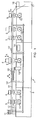
- FIG. 1 shows a schematic side view of an apparatus 1 for the production of tear-open.
- This has on a machine frame 2 several processing stations 3 to 9.
- a conveyor 10, 13, 14 conveys lid parts and the finished lid in the conveying direction, which is indicated by the arrow C, from the beginning of the device at the stack 11 to the end of the device where the lid via slides into the trays 16 or 17 arrive. From the stack 11 lid parts are stacked in a known manner and get into the conveyor.
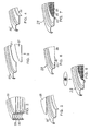
- FIG. 2 shows stacked metal lid blanks 20 as they are ready in the stack 11 at the beginning of the conveyor.
- These blanks 20 are for example round metal discs of eg 11 cm diameter. Of course, other basic shapes, such as square or rectangular discs and other diameters are readily possible.
- the blanks 20 are already in a processing machine, not shown, at its edge as in FIG. 2 shown preformed. In the FIG. 2 and the following ones FIGS. 3 to 9 In each case only one sector of the entire disc or the lid is shown to simplify the figures.
- the first processing station 3 of FIG. 1 is punched by punching with top and bottom tool an opening in the disc, which in FIG. 3 it can be seen in which the edge of the opening is denoted by 21 and the punched round disc with 27.
- This disc 27 arrives as waste in the container 12 of FIG. 1 , This results in an annular cover part 20 'with an opening which forms the removal opening of the finished cover.
- the punching processing station 3 is - as is the case with the other stations - driven by a drive 15.
- the edge 21 is pulled down, whereby, for example, the in FIG. 4 shown shape 22 of the edge is achieved.
- the annular cover parts 20 'then pass into the sealing station 5.
- a film section 25 is punched with punching means 6 and placed over the opening of the cover ring 20' and fixed there by heat sealing, which in the FIGS. 5 and 6 is apparent.
- the tear-open foil 25 which is a metal foil or composite foil or a plastic foil can be, is provided in a known manner on its underside with a sealable plastic layer.
- the tear-open film 25 can be, for example, a multi-layer composite film with plastic layers and aluminum layers, for example having a layer of hot-sealable polypropylene (PP) on the underside of the cover and a following layer of PET followed by an aluminum layer which again is provided with a PET at the top side of the tear-off film Layer is provided. Any printing is then arranged under this PET layer.
- a further embodiment of the tear-open film may be a lid-side or filling material-side hot-seal lacquer layer followed by the aluminum layer and the top-side PET layer.
- the required, in this example round film blank 25 is usually stamped out of a wide film web in the station 5.6 and placed over the central recess of the annular disc and through the sealing station, the film at the edge of the circular recess of the cover part 20 'under heat pressed so that the film 25 is sealed to the metal lid portion 20 'by melting and subsequent cooling of the sealable layer.
- the tear-open lid 28 is formed.
- a cooling processing station 7 may be provided.
- the film 25 can be embossed 24 (FIG. FIG. 7 ), and it is further the edge 22 crimped to the finished edge 23.
- the tab can also be bent so that it comes to rest on the lid.
- a test which usually a leak test for the on the lid applied tearing film 25 includes, for which purpose an air pressure difference between the bottom and top of the lid is generated. If the film is tightly mounted on the cover ring, the cover enters the receptacle 16 for the finished cover. If a leak is detected, the lid passes over the other slide shown in the waste container 17th
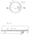
- FIG. 9 shows a finished Aufreissdeckel 28 in plan view.
- the tear-open film 25 is provided with a pull-tab 29, which is bent back onto the lid.
- the tear-open tab is fastened to the cover with an adhesive surface 30, which is preferably formed by a double-sided adhesive tape, in particular with different adhesive force of the two hinge sides. It can also be provided an adhesive surface, which is formed by a sealing wax.
- FIG. 10 shows an enlarged view of the region of the tear-open with the pull-tab 29, which is fastened in the bent-back position detachably on the adhesive surface formed by a piece of double-sided adhesive tape.
- the adhesive tape 33 is preferably adhesively bonded to different degrees on both its sides, so that the adhesion of the adhesive tape to its underside (in the FIG. 10 seen) or at the Aufreissfolien preparation is greater than at its top, where the tear-open tab 29 is held adhesive. This ensures that the tab 29 can be easily detached from the adhesive surface while the adhesive tape remains adhered to the tear-open foil of the lid.
- the edge of the removal opening is provided in this example with a different shape 23 'as in FIG. 7 ,
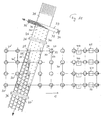
- FIG. 11 shows roughly schematically a part of a device for the production of tear-open, which, for example, a device according to FIG. 1 is.
- conveyor 4 rows lid parts 20, 20 'and cover 28 are conveyed parallel in the conveying direction C.
- a belt 35 of the tear-open film material enters the sealing station and is punched there to form the film sections 25 with the tear-open tab 29.
- the stamping is chosen so that as little as possible stamping waste remains.
- the foil sections 25 for the second top row of lid rings 20 'are punched in the row to the left of the central longitudinal axis of the band 35 and the foil sections 25 for the second bottom row of lid rings 20' are punched out in the row to the right of the central longitudinal axis of the band 35.
- the punched-out foil sections are each sealed onto the associated cover ring, as is known to the person skilled in the art.
- the belt 35 may be conveyed by drive rollers 36 or in other known ways.
- the adhesive surfaces 30 are applied to the belt 35 on its upper side 26. This is done so that at least one such adhesive surface is applied to the tape 35 at each later officersstanzenden film section 25 and that at the point on the film section 25, which later in the finished tear-open lid 28, the bent back flap 29 of this film section comes to rest.
- the punching of the individual film sections 25 in the sealing station can be controlled by printing marks on the belt, for example. These print marks can also be used as aids when the adhesive surfaces 30 are correctly placed, if necessary. But it can also serve as an imprint on the Aufreissfolienabêten itself as a marker.
- a double-sided adhesive tape 33 is passed transversely to the tear-open film belt 35 over this.
- the adhesive tape could also be passed over the belt 35 obliquely or in the same direction.
- a band 33 several individual bands could be provided.
- the double-sided adhesive tape has on its the band 35 opposite bottom, which preferably has stronger adhesion than the top, no protective film.
- a protective film 37 is provided on the upper side, which in the FIG. 11 is visible in plan view.
- a suitable for applying to the tape 35 double-sided adhesive tape with correspondingly different bond strength on the two sides and with one-sided protective film on the less adhesive side is for example the tape tesafix 6917 from tesa Bandfix AG, Bergdietikon, Switzerland.
- This adhesive tape is known to be used for the reversible closure of film bags.
- a punching device FIG. 12
- the adhesive tape running over the belt 35 is punched, so that the adhesive surfaces 30 are punched out of the adhesive tape 33. They are preferably applied by the punching tool directly to the belt 35, where they stick with their protective film-free underside.
- the top of each adhesive surface is covered by the die-cut protective film 37. In band 33, the voids remain 33 '.
- a lid 28 is formed with a tear-open film 25, from which a tab 29 projects beyond the edge of the lid and in which on the lid, a splice 30 is provided, which is still covered with a protective film 37.
- the protective film 37 allows the trouble-free sealing of the tear-open film 25 on the cover ring and protects the adhesive surface 30th
- the protective film 37 is removed and the tab 29 is bent back onto the free adhesive surface 30, where it is fixed by the adhesive, resulting in the in the FIGS. 9 and 10 shown cover 28 leads.
- FIG. 11 In the example of FIG. 11 In this case, in the station 40, the removal of the protective film 37 and in the station 41, the bending back of the tab 29. In between the lid is rotated in a defined position for the bending back, but this can also be done before. At the end of the conveyor line of FIG. 11 then the lid 28 is visible with glued-back tab. The bending back of the tab is already known in the art and will not be explained here. On the other hand, the punching of the splices and the removal of the protective film 37 will be discussed in more detail below.
- an adhesive surface in the form of a surface 30 of sealing wax can be provided for fixing the tab 29 on the cover 28.
- an adhesive can be applied.
- the adhesive surface 30 is applied before punching the film portion 25 on the belt 35 and also applied to a location of the belt 35 on which the flap 29 is bent back in the finished cover 28.
- the sealing lacquer or the adhesive can be printed on the tape 35, for example by means of pressure rollers or by pad printing or they can be sprayed on. This can, as with figure 11 for the adhesive tape, take place directly before sealing the film section 25.
- the application of the splice 30 by means of sealing wax or an adhesive can also be done in advance, especially in the production of the tape 35 from the Aufreissfolienmaterial, wherein in the case of an adhesive cover with a protective film may be provided, which in the formation of the adhesive surface 30 with Sealing wax is not necessary, as this causes no liability until the seal.
- FIG. 12 shows the punching of the subsequent bonding surfaces 30 forming pieces of double-sided adhesive tape 33.
- This is withdrawn from a roll 34 and passed over the belt 35, which in FIG. 12 can be seen cut from the plane of the drawing.
- the belt 35 runs over a support surface 36, so that the punches can press the punched piece of adhesive tape onto the belt 35.
- the construction of driven punching tools 38 for the adhesive tape 33 is a professional measure.
- the band 33 is not adhesive through the protective film 37, so that the punch of each punching tool does not need to be protected against sticking to the adhesive tape.
- the underside of the adhesive tape is adhesive, so that the die and the adjacent areas of the punch with a non-stick coating, such as a Teflon coating must be provided so that the tape does not adhere to the die or its environment during the punching.
- FIGS. 13 and 14 Based on FIGS. 13 and 14 the removal of the protective film 37 from the adhesive surface 30 is explained.
- an air jet 43 obliquely blown from the side of the adhesive surface 30, which raises the protective film and dissolves.
- a suction flow 46 is generated and thus air is sucked off over the adhesive surface, which promotes the dissolved protective film 37.
- FIGS. 13 and 14 show a partially sectioned view of a station 41 without the conveyor or the holding means for the cover 28.
- the edge of the adhesive surface is enlarged relative to a round adhesive surface by the adhesive tape is punched star-shaped or gear-shaped. This promotes detachment of the protective film 37 from the adhesive tape when blowing laterally onto the adhesive surface.
- a suction opening 45 centrally above the adhesive surface 30 can aspirate the detached protective film 37 by means of a suction flow 46 generated by negative pressure.
- a mechanical release by grippers or fingers can be provided, which lift the protective film at least at the edge of the adhesive surface.
- tear-open lids 28 from cover rings 20 'with tear-open foil 25 having a tear-open tab 29, the tear-open tab is thus fixed by an adhesive surface 30, which is applied to the tape from a belt 35 of this material prior to punching out the tear-off foil 25. In this way results in a simple and suitable for the production of tear-open at high speed tab fixation.
Landscapes
- Engineering & Computer Science (AREA)
- Mechanical Engineering (AREA)
- Closures For Containers (AREA)
- Closing Of Containers (AREA)
- Auxiliary Devices For And Details Of Packaging Control (AREA)
Abstract
Description
- Die Erfindung betrifft ein Verfahren zur Herstellung von Aufreissdeckeln, umfassend die Schritte: Zuführen eines Bandes von Aufreissfolienmaterial, Ausstanzen eines Folienabschnitts mit einer Aufreisslasche aus dem Band, Aufsiegeln des Folienabschnitts auf einen Deckelring und Umbiegen der Aufreisslasche auf den Deckel. Ferner betrifft die Erfindung eine Vorrichtung zur Herstellung von Aufreissdeckeln gemäss Anspruch 9 sowie einen Aufreissdeckel gemäss Anspruch 13.
- Es ist bekannt, Deckel für dosen- oder büchsenartige Verpackungen als auf der Verpackung oberseitig permanent befestigte Metalldeckel auszuführen, die einen Deckelring mit einer Entnahmeöffnung aufweisen. Diese bleibt bis zum ersten Gebrauch des Verpackungsinhaltes mittels einer durch Heisssiegelung auf dem Deckelring aufgebrachten, wegreissbaren Folie verschlossen; solche Deckel werden als Aufreissdeckel bezeichnet. Die Folie auf dem Deckel wird als Aufreissfolie bezeichnet und kann z.B. eine Metallfolie, eine Metallverbundfolie oder eine reine Kunststofffolie sein. Ein zusätzlicher, über dem Metalldeckel angeordneter Deckel aus Kunststoff macht die Verpackung während der Verbrauchsdauer des Inhalts wieder verschliessbar. Zum Öffnen des Aufreissdeckels, bzw. zum Wegreissen der aufgesiegelten Folie, weist diese eine Aufreisslasche auf. Beim Verschliessen einer Dose nach deren Befüllung wird der vorgefertigte Aufreissdeckel am Mantel der Dose aufgebördelt. Bei diesem Herstellungsschritt kann eine abstehende Aufreisslasche stören, kann zerknittern und kann sogar abgerissen werden. Das Aufbringen des Kunststoffdeckels ist ferner in der Regel nur möglich, wenn die Lasche zurückgebogen ist. Es ist daher gewünscht, dass die Aufreisslasche auf den Deckel zurückgebogen ist und diese Position beibehält. Dies ist bei Metallfolien möglich, doch kann auch bei diesen Dosen bei der Sterilisation der befüllten und verschlossenen Dose die Wärmeeinwirkung und der Abkühlvorgang eine Verformung und ein unerwünschtes Abstehen der Aufreisslasche bewirken. Bei Verbundfolien aus Metall und Kunststoff oder Folien nur aus Kunststoff ist ein dauerhaftes Zurückbiegen schwieriger und es ergibt sich noch eher ein Abstehen bei der Sterilisation auf Grund von unterschiedlicher Wärmeausdehnung der Schichten. Für Trockenprodukte aufnehmende Dosen, welche nicht sterilisiert werden müssen, ist es bereits bekannt, nach dem Aufsiegeln der Aufreissfolie auf den Deckel die zurückgebogene Aufreisslasche mit Hotmelt-Klebstoff auf dem Deckel zu fixieren. Dieser Produktionsschritt ist allerdings aufwendig. Für zu sterilisierende Dosen ist er zudem nicht verwendbar, da Hotmelt-Klebstoff unter den Sterilisationsbedingungen versagt.
- Bekannte Verfahren bzw. Vorrichtungen zur Herstellung Aufreissdeckeln werden nachfolgend anhand der
Figuren 1 bis 9 näher erläutert. DieFiguren 2 bis 8 dienen dabei zur Erläuterung von Herstellungsschritten. - Der Erfindung liegt die Aufgabe zu Grunde, eine Verbesserung bei Aufreissdeckeln zu schaffen.
- Zur Lösung der Aufgabe erfolgt beim eingangs genannten Verfahren das Aufbringen einer Klebefläche auf das Band vor dem Ausstanzen des Folienabschnitts und an einer Stelle, an welcher beim fertigen Aufreissdeckel die umgebogene Aufreisslasche zu liegen kommt. Ferner wird die Aufgabe mit der Herstellungsvorrichtung nach Anspruch 9 bzw. einem Aufreissdeckel nach Anspruch 13 gelöst.
- Besonders bevorzugt ist das Aufbringen der Klebefläche in der Form eines Stücks doppelseitigen Klebebandes und insbesondere eines Klebebandes mit unterschiedlicher Klebkraft auf den beiden klebenden Seiten, wobei das Band so aufgebracht wird, dass die geringere Klebkraft bei der Aufreisslasche wirksam wird.
- Im Folgenden wird der Stand der Technik und werden Ausführungsbeispiele der Erfindung anhand der Zeichnungen näher erläutert. Dabei zeigt
-
Figur 1 eine schematische Seitenansicht einer Vorrichtung nach Stand der Technik sowie zur Ausführung der vorliegenden Erfindung; -
Figur 2 bis Figur 8 Sektoren von Metalldeckeln zur Erläuterung von deren Herstellung; -
Figur 9 eine Draufsicht auf einen Aufreissdeckel gemäß der Erfindung; -
Figur 10 eine teilweise Schnittdarstellung des Aufreissdeckels vonFigur 9 ; -
Figur 11 eine schematische Ansicht des Aufbringens der Aufreissfolie in der Siegelstation sowie weiterer Schritte; -
Figur 12 eine schematische Ansicht einer Stanzstation für ein doppelseitiges Klebeband; -
Figur 13 eine schematische Schnittansicht der Blas- und Saugeinrichtung zur Entfernung der Schutzfolie von der Klebefläche; und -
Figur 14 eine genauere Ansicht der Entfernung der Schutzfolie. -
Figur 1 zeigt eine schematische Seitenansicht einer Vorrichtung 1 zur Herstellung von Aufreissdeckeln. Diese weist auf einem Maschinengestell 2 mehrere Bearbeitungsstationen 3 bis 9 auf. Eine Fördereinrichtung 10, 13, 14 fördert Deckelteile und die fertigen Deckel in Förderrichtung, welche durch den Pfeil C angedeutet ist, vom Anfang der Vorrichtung beim Stapel 11 bis zum Ende der Vorrichtung, wo die Deckel über Rutschen in die Ablagen 16 oder 17 gelangen. Vom Stapel 11 werden Deckelteile auf bekannte Weise abgestapelt und gelangen in die Fördereinrichtung. Diese kann zwei jeweils einzeln seitlich der Gegenstände angeordnete lange Schienen 10 aufweisen, welche die auf Ablagen 10' bzw. in den Stationen 3 bis 9 liegenden Deckelteile bzw. Deckel beim Anheben der Stangen 10 mittels des Antriebes 14 in Richtung des Pfeils A nach oben anheben und sie danach durch eine Vorwärtsbewegung in Richtung des Pfeils B (gleichgerichtet wie der Pfeil C) durch den Kurbelantrieb 13 um einen Betrag nach vorne versetzen. Danach werden die Stangen in Richtung des Pfeils A nach unten bewegt wobei die Deckelteile und Deckel wiederum auf ihren Ablagestellen abgelegt werden. Die Stangen 10 werden danach unterhalb der Gegenstandsablagepositionen in Pfeilrichtung B entgegen dem Pfeil C nach hinten bewegt um danach den beschriebenen Vorgang erneut durchzuführen. Die Deckelteile bzw. Deckel ruhen zwischen dem Transport auf ihren Ablagepositionen bzw. befinden sich in den Bearbeitungsstationen und werden dort bearbeitet. Nach einem Bearbeitungsschritt durch alle Bearbeitungsstationen erfolgt die erneute Förderung. Anstelle der geschilderten Fördereinrichtung könnte eine bekannte Fördereinrichtung mit zwei Zahnriemen gemässWO 2006/017953 verwendet werden. Ein solcher endloser Zahnriemenantrieb wird in der für die Anzahl der Bearbeitungsstationen notwendigen Länge vorgesehen und die schrittweise, mit den Bearbeitungsstationen synchronisierte Zahnriemenbewegung wird durch einen Schrittmotor oder Servomotor bewirkt, welcher die Zahnriemen durch Zahnrollen antreibt. Die Fördereinrichtung mit Zahnriemen erlaubt die Herstellung von Deckeln mit höherer Taktzahl von z.B. 200 Deckeln pro Minute. -
Figur 2 zeigt gestapelte metallene Deckelrohlinge 20, wie sie im Stapel 11 am Anfang der Fördereinrichtung bereit sind. Diese Rohlinge 20 sind z.B. runde Metallscheiben von z.B. 11 cm Durchmesser. Natürlich sind andere Grundformen, z.B. quadratische oder rechteckige Scheiben und andere Durchmesser ohne weiteres möglich. Die Rohlinge 20 sind bereits in einer nicht dargestellten Bearbeitungsmaschine an ihrem Rand wie inFigur 2 gezeigt vorgeformt worden. In derFigur 2 und den nachfolgendenFiguren 3 bis 9 ist jeweils nur ein Sektor der ganzen Scheibe bzw. des Deckels dargestellt, um die Figuren zu vereinfachen. In der ersten Bearbeitungsstation 3 vonFigur 1 wird durch eine Stanzbearbeitung mit Ober- und Unterwerkzeug eine Öffnung in die Scheibe gestanzt, was inFigur 3 ersichtlich ist, in welcher der Rand der Öffnung mit 21 bezeichnet ist und die ausgestanzte runde Scheibe mit 27. Diese Scheibe 27 gelangt als Abfall in den Behälter 12 vonFigur 1 . Es entsteht somit ein ringförmiger Deckelteil 20' mit einer Öffnung, welche die Entnahmeöffnung des fertigen Deckels bildet. Die Stanzbearbeitungsstation 3 wird - wie dies auch bei den weiteren Stationen der Fall ist - durch einen Antrieb 15 angetrieben. Bei der Bearbeitungsstation 4 erfolgt ein Ziehen des Randes 21 nach unten, wodurch z.B. die inFigur 4 gezeigte Form 22 des Randes erzielt wird. Die ringförmigen Deckelteile 20' gelangen dann in die Siegelstation 5. In dieser wird ein Folienabschnitt 25 mit Stanzmitteln 6 ausgestanzt und über der Öffnung des Deckelrings 20' platziert und dort durch Heissversiegelung befestigt, was in denFiguren 5 und 6 ersichtlich ist. Die Aufreissfolie 25, die eine Metallfolie oder Verbundfolie oder eine Kunststofffolie sein kann, ist dazu auf bekannte Weise an ihrer Unterseite mit einer siegelfähigen Kunststoffschicht versehen. Die Aufreissfolie 25 kann z.B. eine Mehrschichtverbundfolie mit Kunststoffschichten und Aluminiumschichten sein, z.B. an der Deckelunterseite eine Schicht aus heissiegelfähigem Polypropylen (PP) und eine folgende Schicht aus PET aufweisen, die von einer Aluminiumschicht gefolgt ist, welche an der Oberseite der Aufreissfolie wieder mit einer PET-Schicht versehen ist. Eine allfällige Bedruckung ist dann unter dieser PET-Schicht angeordnet. Eine weitere Ausgestaltung der Aufreissfolie kann eine deckelunterseitige bzw. füllgutseitige Heisssiegellackschicht gefolgt von der Aluminiumschicht und der deckeloberseitigen PET-Schicht sein. Auch weitere Ausgestaltungen sind dem Fachmann bekannt und können im Rahmen der vorliegenden Erfindung verwendet werden. Der benötigte, in diesem Beispiel runde Folienzuschnitt 25 wird in der Regel in der Station 5,6 aus einer breiten Folienbahn ausgestanzt und über der Mittelausnehmung der ringförmigen Scheibe plaziert und durch die Siegelstation wird die Folie am Rand der runden Ausnehmung des Deckelteils 20' unter Hitzeinwirkung angepresst, so dass die Folie 25 mit dem metallenen Deckelteil 20' durch Aufschmelzen und nachfolgendes Abkühlen der siegelfähigen Schicht dicht verbunden wird. Dies ist bekannt und wird hier nicht näher erläutert. Damit ist der Aufreissdeckel 28 gebildet. Zur Abkühlung kann allenfalls eine Kühlbearbeitungsstation 7 vorgesehen sein. In einer Bearbeitungsstation 8 kann die Folie 25 mit einer Prägung 24 (Figur 7 ) versehen werden, und es wird weiter der Rand 22 zum fertigen Rand 23 umgebördelt. Ist die Aufreissfolie mit einer Aufreisslasche versehen, so kann ferner die Lasche umgebogen werden, so dass sie auf dem Deckel zu liegen kommt. In einer ebenfalls als Bearbeitungsstation zu bezeichnenden Prüfstation 9 werden die fertigen Deckel einer Prüfung unterzogen, welche in der Regel eine Dichtheitsprüfung für die auf dem Deckel aufgebrachte Aufreissfolie 25 umfasst, wozu eine Luftdruckdifferenz zwischen Unterseite und Oberseite des Deckels erzeugt wird. Ist die Folie dicht auf dem Deckelring befestigt, so gelangt der Deckel in die Aufnahme 16 für die fertigen Deckel. Wird eine Undichtigkeit festgestellt, so gelangt der Deckel über die andere dargestellte Rutsche in den Abfallbehälter 17. -
Figur 9 zeigt einen fertigen Aufreissdeckel 28 in Draufsicht. Bei diesem ist die Aufreissfolie 25 mit einer Aufreisslasche 29 versehen, welche auf den Deckel zurückgebogen ist. Gemäss der Erfindung ist dabei die Aufreisslasche am Deckel mit einer Klebefläche 30 befestigt, welche bevorzugt von einem doppelseitigen Klebeband gebildet ist, insbesondere mit unterschiedlicher Klebkraft der beiden Bandseiten. Es kann auch eine Klebefläche vorgesehen sein, die von einem Siegellack gebildet ist.Figur 10 zeigt eine vergrösserte Darstellung des Bereichs des Aufreissdeckels mit der Aufreisslasche 29, die in der zurückgebogenen Stellung lösbar an der von einem Stück doppeltem Klebeband gebildeten Klebefläche befestigt ist. Die Lasche 29 steht über die Klebefläche 30 vor, damit die Lasche zum Öffnen des Aufreissdeckels einfach gegriffen und von der Klebefläche 30 gelöst werden kann. Bevorzugt ist dabei das Klebeband 33 auf seinen beiden Seiten verschieden stark klebend, so dass die Haftung des Klebebandes an seiner Unterseite (in derFigur 10 gesehen) bzw. an der Aufreissfolienfläche grösser ist als an seiner Oberseite, an der die Aufreisslasche 29 klebend gehalten wird. Dies stellt sicher, dass die Lasche 29 einfach von der Klebefläche gelöst werden kann, während das Klebeband auf der Aufreissfolie des Deckels angeklebt bleibt. Der Rand der Entnahmeöffnung ist in diesem Beispiel mit einer anderen Form 23' versehen als inFigur 7 . - An Hand von
Figur 11 wird das Vorgehen zur Bereitstellung einer bevorzugten Klebefläche 30 in Form eines Stücks doppelseitigen Klebebandes auf dem Aufreissdeckel erläutert. Auch andere Arten von Klebeflächen, wie insbesondere Siegellackflächen, können aufgebracht werden.Figur 11 zeigt grob schematisch einen Teil einer Vorrichtung zur Herstellung von Aufreissdeckeln, welche z.B. eine Vorrichtung gemässFigur 1 ist. Mit der inFigur 11 nicht dargestellten Fördereinrichtung werden 4 Reihen Deckelteile 20, 20' bzw. Deckel 28 parallel in Förderrichtung C gefördert. Im Bereich der apparativ nicht gezeigten Siegelstation (entsprechend der Siegelstation 5 und 6 vonFigur 1 ) läuft ein Band 35 des Aufreissfolienmaterials in die Siegelstation ein und wird dort gestanzt, um die Folienabschnitte 25 mit der Aufreisslasche 29 zu bilden. Das Stanzbild wird dabei so gewählt, dass möglichst wenig Stanzabfall bleibt. Die Folienabschnitte 25 für die in derFigur 11 oberste Reihe der Deckelringe 20' werden in diesem Beispiel im Band 35 in der Reihe ganz links am Rand des Bandes ausgestanzt. Es verbleiben danach die Leerstellen 25'. Die Folienabschnitte 25 für die zweitoberste Reihe von Deckelringen 20' werden in der Reihe links der Mittellängsachse des Bandes 35 und die Folienabschnitte 25 für die zweitunterste Reihe von Deckelringen 20' werden in der Reihe rechts von der Mittellängsachse des Bandes 35 ausgestanzt. Die Folienabschnitte 25 für die unterste Reihe der Deckelringe 20' werden in der Reihe ganz rechts des Bandes 35 ausgestanzt. Die ausgestanzten Folienabschnitte werden jeweils auf den zugehörigen Deckelring aufgesiegelt, wie dies dem Fachmann bekannt ist. Das Band 35 kann mit Antriebswalzen 36 oder auf andere bekannte Weise gefördert werden. Vor dem Ausstanzen der Folienabschnitte 25 werden auf dem Band 35 auf dessen Oberseite 26 die Klebeflächen 30 aufgebracht. Dies erfolgt so, dass auf dem Band 35 bei jedem jeweils später auszustanzenden Folienabschnitt 25 mindestens eine solche Klebefläche aufgebracht wird und zwar an derjenigen Stelle auf dem Folienabschnitt 25, an welcher später beim fertigen Aufreissdeckel 28 die zurückgebogene Lasche 29 dieses Folienabschnitts zu liegen kommt. Die Stanzung der einzelnen Folienabschnitte 25 in der Siegelstation kann z.B. durch Druckmarken auf dem Band gesteuert sein. Diese Druckmarken können auch bei der richtigen Platzierung der Klebeflächen 30 als Hilfsmittel dienen, falls nötig. Es kann aber auch ein Aufdruck auf den Aufreissfolienabschnitten selber als Markierung dienen. - In dem gezeigten Beispiel wird ein doppelseitiges Klebeband 33 quer zum Aufreissfolienband 35 über dieses geführt. Dies ist ein bevorzugtes Beispiel, das Klebeband könnte aber auch schräg oder in gleicher Richtung über das Band 35 geführt werden. Anstelle eines Bandes 33 könnten auch mehrere einzelne Bänder vorgesehen sein. Das doppelseitige Klebeband weist dabei an seiner dem Band 35 gegenüber liegenden Unterseite, die vorzugsweise stärkere Klebkraft aufweist als die Oberseite, keine Schutzfolie auf. Hingegen ist eine Schutzfolie 37 auf der Oberseite vorgesehen, welche in der
Figur 11 in Draufsicht ersichtlich ist. Ein für das Aufbringen auf das Band 35 geeignetes doppelseitiges Klebeband mit entsprechend unterschiedlicher Klebkraft auf den beiden Seiten und mit einseitiger Schutzfolie auf der weniger stark klebenden Seite, ist z.B. das Klebeband tesafix 6917 der Firma tesa Bandfix AG, Bergdietikon, Schweiz. Diese Klebeband wird bekanntermassen für den reversiblen Verschluss von Folienbeuteln verwendt. Durch eine Stanzeinrichtung (Figur 12 ) wird das über dem Band 35 verlaufende Klebeband gestanzt, so dass die Klebeflächen 30 aus dem Klebeband 33 ausgestanzt werden. Sie werden bevorzugt von dem Stanzwerkzeug direkt auf das Band 35 aufgebracht, wo sie mit ihrer schutzfolienfreien Unterseite kleben. Die Oberseite jeder Klebefläche bleibt durch die mitgestanzte Schutzfolie 37 abgedeckt. Im Band 33 bleiben die Leerstellen 33'. - Wie in
Figur 11 bei den Aufreissdeckeln 28, die in Förderrichtung C direkt nach dem Band 35 sichtbar sind, dargestellt, wird so jeweils ein Deckel 28 mit einer Aufreissfolie 25 gebildet, von welcher eine Lasche 29 über den Deckelrand vorsteht und bei welchem auf dem Deckel eine Klebestelle 30 vorgesehen ist, welche noch mit einer Schutzfolie 37 abgedeckt ist. Die Schutzfolie 37 ermöglicht dabei das störungsfreie Aufsiegeln der Aufreissfolie 25 auf den Deckelring und schützt die Klebefläche 30. - Danach wird die Schutzfolie 37 entfernt und die Lasche 29 wird auf die freie Klebefläche 30 zurückgebogen, wo sie durch den Klebstoff fixiert wird, was zu dem in den
Figuren 9 und 10 gezeigten Deckel 28 führt. In dem Beispiel vonFigur 11 erfolgt dabei in der Station 40 das Entfernen der Schutzfolie 37 und in der Station 41 das Zurückbiegen der Lasche 29. Dazwischen wird der Deckel in eine definierte Lage für das Zurückbiegen gedreht, was allerdings auch schon vorher erfolgen kann. Am Ende der Förderstrecke vonFigur 11 ist dann der Deckel 28 mit angeklebter zurückgebogener Lasche ersichtlich. Das Zurückbiegen der Lasche ist dabei dem Fachmann bereits bekannt und wird hier nicht näher erläutert. Hingegen wird unten genauer auf das Ausstanzen der Klebestellen und auf das Entfernen der Schutzfolie 37 eingegangen. - Anstelle des bevorzugten doppelseitigen Klebebandes kann zum Fixieren der Lasche 29 auf dem Deckel 28 auch eine Klebefläche in Form einer Fläche 30 aus Siegellack vorgesehen werden. Anstelle eines Siegellacks kann auch ein Klebstoff aufgebracht werden. Auch in diesen Fällen wird die Klebefläche 30 vor dem Ausstanzen des Folienabschnitts 25 auf dem Band 35 aufgebracht und auch dabei erfolgt das Aufbringen auf eine Stelle des Bandes 35 auf welche beim fertigen Deckel 28 die Lasche 29 zurückgebogen wird. Der Siegellack oder der Klebstoff können auf das Band 35 aufgedruckt werden, z.B. mittels Druckwalzen oder mittels Tampondruck oder sie können aufgesprüht werden. Dies kann, wie mit
Figur 11 für das Klebeband gezeigt, direkt vor der Siegelung des Folienabschnitts 25 erfolgen. Das Aufbringen der Klebestelle 30 mittels Siegellack oder einem Klebstoff kann aber auch bereits vorgängig, insbesondere bei der Herstellung des Bandes 35 aus dem Aufreissfolienmaterial erfolgen, wobei im Falle eines Klebstoffes eine Abdeckung mit einer Schutzfolie vorgesehen sein kann, welche bei der Bildung der Klebefläche 30 mit Siegellack nicht notwendig ist, da dieser bis zur Siegelung keine Haftung bewirkt. - Im Falle des Siegellacks ist dann ein weiterer Siegelvorgang an der Klebefläche 30 erforderlich, wenn die Lasche 29 zurückgebogen wird. Dies kann in der Station erfolgen, in welcher die Prägung aufgebracht wird (
Figur 7 ). Es kann aber auch eine separate Siegelstation für diesen Schritt vorgesehen sein, z.B. anstelle der inFigur 11 gezeigten Entfernung der Schutzfolie, wobei dann 40 eine Station für das Umbiegen und Siegeln der Lasche 29 bezeichnen kann und die Station 41 entfallen würde. -
Figur 12 zeigt das Ausstanzen der anschliessend die Klebeflächen 30 bildenden Stücke aus dem doppelseitigen Klebeband 33. Dieses wird von einer Rolle 34 abgezogen und über das Band 35 geführt, welches inFigur 12 von der Zeichnungsebene geschnitten ersichtlich ist. Im Bereich der vier angetriebenen Stanzen 38 läuft das Band 35 über eine Stützfläche 36, damit die Stanzwerkzeuge das ausgestanzte Klebebandstück auf das Band 35 andrücken können. Der Aufbau von angetriebenen Stanzwerkzeugen 38 für das Klebeband 33 ist eine fachmännische Massnahme. Auf seiner Oberfläche ist das Band 33 durch die Schutzfolie 37 nicht klebend, so dass der Stempel jedes Stanzwerkzeugs nicht gegen ein Kleben am Klebeband geschützt zu werden braucht. Die Unterseite des Klebebandes ist klebend, so dass die Matrize und die benachbarten Bereiche des Stanzwerkzeuges mit einer Antihaftbeschichtung, z.B. einer Teflonbeschichtung zu versehen sind, damit das Klebeband bei der Stanzung nicht an der Matrize oder deren Umgebung haftet. - An Hand der
Figuren 13 und 14 wird die Entfernung der Schutzfolie 37 von der Klebefläche 30 erläutert. Dabei wird einerseits mit einem Luftstrahl 43 schräg von der Seite auf die Klebefläche 30 geblasen, was die Schutzfolie anhebt und löst. Andererseits wird eine Saugströmung 46 erzeugt und somit Luft über der Klebefläche abgesaugt, was die gelöste Schutzfolie 37 wegfördert. DieFiguren 13 und 14 zeigen eine teilweise geschnittene Darstellung einer Station 41 ohne die Fördereinrichtung bzw. die Haltemittel für den Deckel 28. Bevorzugt wird über eine Ringdüse 44 mit Pfeilen 43 angedeutete Druckluft ringsherum schräg auf den Rand der Klebefläche 30 geblasen. Bevorzugt ist der Rand der Klebefläche gegenüber einer runden Klebefläche vergrößert, indem das Klebeband sternförmig oder zahnradförmig ausgestanzt wird. Dies fördert das Ablösen der Schutzfolie 37 vom Klebeband, wenn seitlich auf die Klebefläche geblasen wird. Eine Absaugöffnung 45 zentral über der Klebefläche 30 kann die abgelöste Schutzfolie 37 mittels einer durch Unterdruck erzeugten Saugströmung 46 absaugen. Zusätzlich zum Lösen der Schutzfolie 37 durch Luft kann ein mechanisches Lösen durch Greifer oder Finger vorgesehen sein, welche die Schutzfolie mindestens am Rand der Klebefläche anheben. - Bei der Herstellung von Aufreissdeckeln 28 aus Deckelringen 20' mit darauf aufgesiegelter Aufreissfolie 25 mit einer Aufreisslasche 29 wird somit die Aufreisslasche durch eine Klebefläche 30 fixiert, welche vor dem Ausstanzen der Aufreissfolie 25 aus einem Band 35 dieses Materials auf das Band aufgebracht wird. Auf diese Weise ergibt sich eine einfache und für die Produktion von Aufreissdeckeln mit hoher Geschwindigkeit geeignete Laschenfixierung.
Claims (13)
- Verfahren zur Herstellung von Aufreissdeckeln (28), umfassend die Schritte- Zuführen eines Bandes (35) von Aufreissfolienmaterial;- Ausstanzen eines Folienabschnitts (25) mit einer Aufreisslasche (29) aus dem Band (35);- Aufsiegeln des Folienabschnitts (25) auf einem Deckelring (20'); und- Umbiegen der Aufreisslasche (29) auf den Deckel (28), gekennzeichnet durch den Schritt- Aufbringen einer Klebefläche (30) auf das Band (35) vor dem Ausstanzen des Folienabschnitts (25), an einer Stelle, an welcher beim Aufreissdeckel (28) die umgebogene Aufreisslasche (29) zu liegen kommt.
- Verfahren nach Anspruch 1, dadurch gekennzeichnet, dass die Klebefläche (30) als Stück eines doppelseitigen Klebebandes (33) aufgebracht wird.
- Verfahren nach Anspruch 2, dadurch gekennzeichnet, dass ein Klebeband (33) aufgebracht wird, welches verschieden starke Klebkraft auf seinen beiden Seiten aufweist, wobei die Klebkraft auf der der Aufreisslasche (29) zuweisenden Seite geringer ist.
- Verfahren nach Anspruch 2 oder 3, dadurch gekennzeichnet, dass das Stück oberhalb des Bandes (35) aus dem Klebeband (33) ausgestanzt und direkt danach auf das Band (35) aufgebracht wird.
- Verfahren nach einem der Ansprüche 2 bis 4, dadurch gekennzeichnet, dass das Klebeband an seiner Oberseite mit einer Schutzfolie (37) versehen ist, welche vor dem Umbiegen der Aufreisslasche (29) entfernt wird.
- Verfahren nach Anspruch 5, dadurch gekennzeichnet, dass die Schutzfolie (37) mit mindestens einem Luftstrahl (43) gelöst, und dass die gelöste Schutzfolie (37) durch eine Saugströmung (46) abgesaugt wird.
- Verfahren nach Anspruch 1, dadurch gekennzeichnet, dass die Klebefläche in flüssiger Form aufgebracht wird.
- Verfahren nach Anspruch 7, dadurch gekennzeichnet, dass als Klebefläche ein Siegellack aufgebracht wird, insbesondere durch Drucken oder Sprühen, und dass beim Umbiegen der Lasche (29) zurück auf den Deckel eine Siegelung zur Fixierung der Lasche erfolgt.
- Vorrichtung zur Herstellung von Aufreissdeckeln (28), umfassend eine Fördereinrichtung für Deckelteile und Deckel (20, 20', 28), eine Siegelstation (5, 6), in welcher durch Zuführmittel (36) ein Band (35) aus Aufreissfolienmaterial zuführbar ist, wobei die Siegelstation zum Ausstanzen eines Folienabschnitts (25) mit einer Aufreisslasche (29) aus dem Band (35) und zum Aufsiegeln des Folienabschnitts (25) mit dessen siegelfähiger Unterseite auf einen Deckelring (20') ausgestaltet ist, sowie eine Umbiegestation (42), in welcher die Aufreisslasche (29) auf den Deckel biegbar ist, dadurch gekennzeichnet, dass eine Einrichtung (38, 39) vorgesehen ist, durch welche vor dem Ausstanzen des Folienabschnitts (25) eine Klebefläche (30) auf die Oberseite (26) des Bands (35) aufbringbar ist.
- Vorrichtung nach Anspruch 9, dadurch gekennzeichnet, dass die Einrichtung mindestens eine Zuführung für mindestens ein Klebeband (33) sowie mindestens ein Stanzwerkzeug (38) aufweist, durch welches die Klebefläche (30) aus dem Klebeband (33) ausstanzbar und auf die Oberseite (26) des Bands (35) aufbringbar ist.
- Vorrichtung nach Anspruch 9 oder 10,
dadurch gekennzeichnet, dass eine Einrichtung (41) zur Entfernung einer Schutzfolie (37) von der Klebefläche vorgesehen ist. - Vorrichtung nach Anspruch 11, dadurch gekennzeichnet, dass die Einrichtung zur Beaufschlagung der Klebefläche mit Druckluft (43) und zur Absaugung der gelösten Schutzfolie ausgestaltet ist.
- Aufreissdeckel (28) mit einem Deckelring (20') und einer Aufreissfolie (25) mit einer umgebogenen Aufreisslasche (29), dadurch gekennzeichnet, dass die Aufreisslasche (29) auf der Aufreissfolie durch ein eine Klebefläche (30) befestigt ist, welche von einem Stück doppelseitigen Klebeband (33) gebildet ist, dessen Klebkraft auf seinen beiden Seiten unterschiedlich ist, wobei die geringere Klebkraft auf der Seite wirkt, an welcher die Aufreisslasche befestigt ist.
Applications Claiming Priority (1)
| Application Number | Priority Date | Filing Date | Title |
|---|---|---|---|
| CH00061/09A CH700263A1 (de) | 2009-01-16 | 2009-01-16 | Verfahren und Vorrichtung zur Herstellung von Aufreissdeckeln. |
Publications (3)
| Publication Number | Publication Date |
|---|---|
| EP2208554A2 true EP2208554A2 (de) | 2010-07-21 |
| EP2208554A3 EP2208554A3 (de) | 2011-02-16 |
| EP2208554B1 EP2208554B1 (de) | 2012-03-07 |
Family
ID=42167349
Family Applications (1)
| Application Number | Title | Priority Date | Filing Date |
|---|---|---|---|
| EP10000342A Not-in-force EP2208554B1 (de) | 2009-01-16 | 2010-01-15 | Verfahren und Vorrichtung zur Herstellung von Aufreissdeckeln |
Country Status (6)
| Country | Link |
|---|---|
| US (1) | US20100183406A1 (de) |
| EP (1) | EP2208554B1 (de) |
| AT (1) | ATE548138T1 (de) |
| CH (2) | CH700263A1 (de) |
| ES (1) | ES2379859T3 (de) |
| PT (1) | PT2208554E (de) |
Cited By (2)
| Publication number | Priority date | Publication date | Assignee | Title |
|---|---|---|---|---|
| CH704695A1 (de) * | 2011-03-25 | 2012-09-28 | Soudronic Ag | Vorrichtung und Verfahren zur Herstellung von Aufreissdeckeln. |
| WO2012143322A1 (en) * | 2011-04-20 | 2012-10-26 | Crown Packaging Technology, Inc. | Method for forming a metal closure |
Families Citing this family (5)
| Publication number | Priority date | Publication date | Assignee | Title |
|---|---|---|---|---|
| ES2527928T3 (es) * | 2008-08-21 | 2015-02-02 | Ardagh Mp Group Netherlands B.V. | Tapa para un bote y método para orientar dicha tapa |
| TWI589494B (zh) | 2014-03-28 | 2017-07-01 | World Bottling Cap Llc | 具有開瓶器組件的冠形瓶蓋 |
| US20170129643A9 (en) | 2014-03-28 | 2017-05-11 | World Bottling Cap Llc | Bottle crown with opener assembly |
| CN107695234B (zh) * | 2017-11-23 | 2023-11-14 | 天津普润泽实业有限公司 | 易拉瓶盖一出多个成型装置及其成型方法 |
| KR102858249B1 (ko) * | 2023-11-27 | 2025-09-11 | (주)제로투세븐 | 당김손잡이의 들뜸이 방지된 분말 용기의 캡 및 이의 제조 방법 |
Citations (1)
| Publication number | Priority date | Publication date | Assignee | Title |
|---|---|---|---|---|
| WO2006017953A1 (de) | 2004-08-18 | 2006-02-23 | Soudronic Ag | Verfahren und vorrichtung zum fördern von zu bearbeitenden gegenständen |
Family Cites Families (12)
| Publication number | Priority date | Publication date | Assignee | Title |
|---|---|---|---|---|
| US4741450A (en) * | 1986-04-28 | 1988-05-03 | Elton Braude | Drink-through beverage lid |
| US4846774A (en) * | 1988-01-26 | 1989-07-11 | Bernal Rotary Systems, Inc. | Rotary die cutting and laminating process and machine |
| RU2223208C2 (ru) * | 1998-01-07 | 2004-02-10 | Джордж Б. Даймонд | Повторно закрываемая легко открываемая крышка и банка |
| EP1386852A1 (de) * | 2002-07-26 | 2004-02-04 | Crown Cork & Seal Technologies Corporation | Deckelstruktur |
| CH705057B1 (de) * | 2003-05-13 | 2012-12-14 | Soudronic Ag | Bearbeitungseinrichtung und Verwendung derselben zur Herstellung von Deckeln mit Aufreissfolie. |
| DE102004012556A1 (de) * | 2004-03-15 | 2005-10-06 | Vitus Maria Huber | Verpackungsvorrichtung für flüssige oder pastöse Medien, insbesondere für Milchprodukte |
| US7588525B2 (en) * | 2004-09-13 | 2009-09-15 | Crown Packaging Technology, Inc. | Tab folding and sealing apparatus and method |
| CH703157B1 (de) * | 2004-11-19 | 2011-11-30 | Soudronic Ag | Deckelring sowie damit versehener Deckel. |
| DE102007017339A1 (de) * | 2006-11-17 | 2008-05-21 | Huhtamaki Ronsberg, Zweigniederlassung Der Huhtamaki Deutschland Gmbh & Co. Kg | Behälter, insbesondere flexibler schlauchbeutel-und/oder dosenartiger Verpackungsbehälter |
| IES20060949A2 (en) * | 2006-12-21 | 2008-09-17 | Anne Houston | A collecting system suitable for collecting and disposing of bodliy waste materials |
| US8231024B2 (en) * | 2007-08-08 | 2012-07-31 | Clear Lam Packaging, Inc. | Flexible, stackable container and method and system for manufacturing same |
| DE202008014733U1 (de) * | 2008-11-06 | 2010-03-25 | Naroska, Markus | Aufreissbare Siegelverpackung |
-
2009
- 2009-01-16 CH CH00061/09A patent/CH700263A1/de not_active Application Discontinuation
- 2009-08-12 CH CH01249/09A patent/CH700257A1/de unknown
-
2010
- 2010-01-15 ES ES10000342T patent/ES2379859T3/es active Active
- 2010-01-15 AT AT10000342T patent/ATE548138T1/de active
- 2010-01-15 EP EP10000342A patent/EP2208554B1/de not_active Not-in-force
- 2010-01-15 PT PT10000342T patent/PT2208554E/pt unknown
- 2010-01-15 US US12/687,923 patent/US20100183406A1/en not_active Abandoned
Patent Citations (1)
| Publication number | Priority date | Publication date | Assignee | Title |
|---|---|---|---|---|
| WO2006017953A1 (de) | 2004-08-18 | 2006-02-23 | Soudronic Ag | Verfahren und vorrichtung zum fördern von zu bearbeitenden gegenständen |
Cited By (7)
| Publication number | Priority date | Publication date | Assignee | Title |
|---|---|---|---|---|
| CH704695A1 (de) * | 2011-03-25 | 2012-09-28 | Soudronic Ag | Vorrichtung und Verfahren zur Herstellung von Aufreissdeckeln. |
| WO2012129710A1 (de) | 2011-03-25 | 2012-10-04 | Soudronic Ag | Vorrichtung und verfahren zur herstellung von aufreissdeckeln |
| CN103459061A (zh) * | 2011-03-25 | 2013-12-18 | 苏德罗尼克股份公司 | 撕去盖的制造设备和方法 |
| CN103459061B (zh) * | 2011-03-25 | 2015-11-25 | 苏德罗尼克股份公司 | 撕去盖的制造设备和方法 |
| US9308712B2 (en) | 2011-03-25 | 2016-04-12 | Soudronic Ag | Apparatus and method for manufacturing tear-off lids |
| WO2012143322A1 (en) * | 2011-04-20 | 2012-10-26 | Crown Packaging Technology, Inc. | Method for forming a metal closure |
| US9968983B2 (en) | 2011-04-20 | 2018-05-15 | Crown Packaging Technology, Inc. | Method for forming a metal closure |
Also Published As
| Publication number | Publication date |
|---|---|
| CH700257A1 (de) | 2010-07-30 |
| EP2208554A3 (de) | 2011-02-16 |
| CH700263A1 (de) | 2010-07-30 |
| EP2208554B1 (de) | 2012-03-07 |
| ES2379859T3 (es) | 2012-05-04 |
| PT2208554E (pt) | 2012-05-30 |
| US20100183406A1 (en) | 2010-07-22 |
| ATE548138T1 (de) | 2012-03-15 |
Similar Documents
| Publication | Publication Date | Title |
|---|---|---|
| EP2208554B1 (de) | Verfahren und Vorrichtung zur Herstellung von Aufreissdeckeln | |
| EP2272602B1 (de) | Verfahren und Vorrichtung zur Herstellung von Aufreissdeckeln und solcher Aufreissdeckel | |
| EP1624984B1 (de) | Bearbeitungseinrichtung und verwendung derselben zur herstellung von deckeln mit aufreissfolie | |
| EP2151286A2 (de) | Einrichtung und Verfahren zur Herstellung von Deckeln mit Aufreissfolie | |
| EP0952080A1 (de) | Verfahren zum Herstellen von gefüllten und mit aufgesiegelten Deckfolienzuschnitten verschlossenen Trinkbechern | |
| DE102016003737A1 (de) | Zigarettenpackung sowie Verfahren und Vorrichtung zum Herstellen derselben | |
| DE2810899C2 (de) | Verfahren zur Herstellung und Füllung eines Behälters, wie Becher oder Flasche, aus thermoplastischem Material | |
| EP4296191A1 (de) | Verpackung und verfahren zum herstellen einer verpackung | |
| EP3642117B1 (de) | Vorrichtung zur verpackung, insbesondere von obst und gemüse | |
| EP1238921B1 (de) | Trinkhalmanbringvorrichtung und -verfahren | |
| EP2688697B1 (de) | Vorrichtung und verfahren zur herstellung von aufreissdeckeln | |
| WO2019020139A2 (de) | Vorrichtung und verfahren zur herstellung von siegelrandbeuteln | |
| DE19523754A1 (de) | Foliendeckel zum Verschließen von Behältern, Folienbahn zur Herstellung solcher Foliendeckel und Verfahren zur Herstellung einer solchen Folienbahn | |
| EP2684803B1 (de) | Verfahren zum Herstellen einer Verpackung | |
| EP3438019B1 (de) | Zigarettenpackung und verfahren zum herstellen derselben | |
| EP1858767B1 (de) | Aufreissdeckel und verfahren zu dessen herstellung | |
| EP1819501B1 (de) | Siegelmaschine und verfahren | |
| DE102023109287A1 (de) | Verpackung und Verfahren zum Herstellen einer Verpackung | |
| EP1923323B1 (de) | Träger für Dosen, zu dessen Herstellung bestimmter Zuschnitt aus Kraftkarton sowie Verpackungsmaschine zur Herstellung von Verpackungseinheiten aus diesen Trägern und Dosen | |
| EP1165309B1 (de) | Verfahren zur herstellung einer verbundpackung und danach hergestellte verbundpackung | |
| EP0511358B1 (de) | Verfahren und vorrichtung zum verschliessen einer öffnung eines rohrförmigen behälters | |
| CH701925A1 (de) | Aufreissdeckel sowie Vorrichtung und Verfahren zu seiner Herstellung sowie Behälter mit einem solchen. | |
| DE202008003877U1 (de) | Verschlussetikett für Verpackungen | |
| DE102023134626A1 (de) | Verpackung und Verfahren zum Herstellen einer Verpackung | |
| EP4714646A1 (de) | Verfahren zur herstellung eines haftverbunds mit innenliegenden ausgestanzten ausnehmungen |
Legal Events
| Date | Code | Title | Description |
|---|---|---|---|
| PUAI | Public reference made under article 153(3) epc to a published international application that has entered the european phase |
Free format text: ORIGINAL CODE: 0009012 |
|
| AK | Designated contracting states |
Kind code of ref document: A2 Designated state(s): AT BE BG CH CY CZ DE DK EE ES FI FR GB GR HR HU IE IS IT LI LT LU LV MC MK MT NL NO PL PT RO SE SI SK SM TR |
|
| AX | Request for extension of the european patent |
Extension state: AL BA RS |
|
| PUAL | Search report despatched |
Free format text: ORIGINAL CODE: 0009013 |
|
| AK | Designated contracting states |
Kind code of ref document: A3 Designated state(s): AT BE BG CH CY CZ DE DK EE ES FI FR GB GR HR HU IE IS IT LI LT LU LV MC MK MT NL NO PL PT RO SE SI SK SM TR |
|
| AX | Request for extension of the european patent |
Extension state: AL BA RS |
|
| RIC1 | Information provided on ipc code assigned before grant |
Ipc: B21D 51/38 20060101AFI20100521BHEP Ipc: B21D 51/44 20060101ALI20110111BHEP Ipc: B65D 17/50 20060101ALI20110111BHEP |
|
| 17P | Request for examination filed |
Effective date: 20110809 |
|
| GRAP | Despatch of communication of intention to grant a patent |
Free format text: ORIGINAL CODE: EPIDOSNIGR1 |
|
| GRAS | Grant fee paid |
Free format text: ORIGINAL CODE: EPIDOSNIGR3 |
|
| GRAA | (expected) grant |
Free format text: ORIGINAL CODE: 0009210 |
|
| AK | Designated contracting states |
Kind code of ref document: B1 Designated state(s): AT BE BG CH CY CZ DE DK EE ES FI FR GB GR HR HU IE IS IT LI LT LU LV MC MK MT NL NO PL PT RO SE SI SK SM TR |
|
| REG | Reference to a national code |
Ref country code: GB Ref legal event code: FG4D Free format text: NOT ENGLISH |
|
| REG | Reference to a national code |
Ref country code: CH Ref legal event code: NV Representative=s name: E. BLUM & CO. AG PATENT- UND MARKENANWAELTE VSP Ref country code: CH Ref legal event code: EP Ref country code: AT Ref legal event code: REF Ref document number: 548138 Country of ref document: AT Kind code of ref document: T Effective date: 20120315 |
|
| REG | Reference to a national code |
Ref country code: IE Ref legal event code: FG4D Free format text: LANGUAGE OF EP DOCUMENT: GERMAN |
|
| REG | Reference to a national code |
Ref country code: DE Ref legal event code: R096 Ref document number: 502010000472 Country of ref document: DE Effective date: 20120503 |
|
| REG | Reference to a national code |
Ref country code: ES Ref legal event code: FG2A Ref document number: 2379859 Country of ref document: ES Kind code of ref document: T3 Effective date: 20120504 |
|
| REG | Reference to a national code |
Ref country code: PT Ref legal event code: SC4A Free format text: AVAILABILITY OF NATIONAL TRANSLATION Effective date: 20120523 |
|
| REG | Reference to a national code |
Ref country code: NL Ref legal event code: T3 |
|
| PG25 | Lapsed in a contracting state [announced via postgrant information from national office to epo] |
Ref country code: NO Free format text: LAPSE BECAUSE OF FAILURE TO SUBMIT A TRANSLATION OF THE DESCRIPTION OR TO PAY THE FEE WITHIN THE PRESCRIBED TIME-LIMIT Effective date: 20120607 Ref country code: LT Free format text: LAPSE BECAUSE OF FAILURE TO SUBMIT A TRANSLATION OF THE DESCRIPTION OR TO PAY THE FEE WITHIN THE PRESCRIBED TIME-LIMIT Effective date: 20120307 Ref country code: HR Free format text: LAPSE BECAUSE OF FAILURE TO SUBMIT A TRANSLATION OF THE DESCRIPTION OR TO PAY THE FEE WITHIN THE PRESCRIBED TIME-LIMIT Effective date: 20120307 |
|
| LTIE | Lt: invalidation of european patent or patent extension |
Effective date: 20120307 |
|
| PG25 | Lapsed in a contracting state [announced via postgrant information from national office to epo] |
Ref country code: GR Free format text: LAPSE BECAUSE OF FAILURE TO SUBMIT A TRANSLATION OF THE DESCRIPTION OR TO PAY THE FEE WITHIN THE PRESCRIBED TIME-LIMIT Effective date: 20120608 Ref country code: FI Free format text: LAPSE BECAUSE OF FAILURE TO SUBMIT A TRANSLATION OF THE DESCRIPTION OR TO PAY THE FEE WITHIN THE PRESCRIBED TIME-LIMIT Effective date: 20120307 Ref country code: LV Free format text: LAPSE BECAUSE OF FAILURE TO SUBMIT A TRANSLATION OF THE DESCRIPTION OR TO PAY THE FEE WITHIN THE PRESCRIBED TIME-LIMIT Effective date: 20120307 |
|
| PG25 | Lapsed in a contracting state [announced via postgrant information from national office to epo] |
Ref country code: CY Free format text: LAPSE BECAUSE OF FAILURE TO SUBMIT A TRANSLATION OF THE DESCRIPTION OR TO PAY THE FEE WITHIN THE PRESCRIBED TIME-LIMIT Effective date: 20120307 |
|
| PG25 | Lapsed in a contracting state [announced via postgrant information from national office to epo] |
Ref country code: PL Free format text: LAPSE BECAUSE OF FAILURE TO SUBMIT A TRANSLATION OF THE DESCRIPTION OR TO PAY THE FEE WITHIN THE PRESCRIBED TIME-LIMIT Effective date: 20120307 Ref country code: EE Free format text: LAPSE BECAUSE OF FAILURE TO SUBMIT A TRANSLATION OF THE DESCRIPTION OR TO PAY THE FEE WITHIN THE PRESCRIBED TIME-LIMIT Effective date: 20120307 Ref country code: CZ Free format text: LAPSE BECAUSE OF FAILURE TO SUBMIT A TRANSLATION OF THE DESCRIPTION OR TO PAY THE FEE WITHIN THE PRESCRIBED TIME-LIMIT Effective date: 20120307 Ref country code: SE Free format text: LAPSE BECAUSE OF FAILURE TO SUBMIT A TRANSLATION OF THE DESCRIPTION OR TO PAY THE FEE WITHIN THE PRESCRIBED TIME-LIMIT Effective date: 20120307 Ref country code: IS Free format text: LAPSE BECAUSE OF FAILURE TO SUBMIT A TRANSLATION OF THE DESCRIPTION OR TO PAY THE FEE WITHIN THE PRESCRIBED TIME-LIMIT Effective date: 20120707 Ref country code: SI Free format text: LAPSE BECAUSE OF FAILURE TO SUBMIT A TRANSLATION OF THE DESCRIPTION OR TO PAY THE FEE WITHIN THE PRESCRIBED TIME-LIMIT Effective date: 20120307 Ref country code: RO Free format text: LAPSE BECAUSE OF FAILURE TO SUBMIT A TRANSLATION OF THE DESCRIPTION OR TO PAY THE FEE WITHIN THE PRESCRIBED TIME-LIMIT Effective date: 20120307 |
|
| PG25 | Lapsed in a contracting state [announced via postgrant information from national office to epo] |
Ref country code: SK Free format text: LAPSE BECAUSE OF FAILURE TO SUBMIT A TRANSLATION OF THE DESCRIPTION OR TO PAY THE FEE WITHIN THE PRESCRIBED TIME-LIMIT Effective date: 20120307 |
|
| PLBE | No opposition filed within time limit |
Free format text: ORIGINAL CODE: 0009261 |
|
| STAA | Information on the status of an ep patent application or granted ep patent |
Free format text: STATUS: NO OPPOSITION FILED WITHIN TIME LIMIT |
|
| PG25 | Lapsed in a contracting state [announced via postgrant information from national office to epo] |
Ref country code: DK Free format text: LAPSE BECAUSE OF FAILURE TO SUBMIT A TRANSLATION OF THE DESCRIPTION OR TO PAY THE FEE WITHIN THE PRESCRIBED TIME-LIMIT Effective date: 20120307 |
|
| 26N | No opposition filed |
Effective date: 20121210 |
|
| REG | Reference to a national code |
Ref country code: DE Ref legal event code: R097 Ref document number: 502010000472 Country of ref document: DE Effective date: 20121210 |
|
| BERE | Be: lapsed |
Owner name: SOUDRONIC A.G. Effective date: 20130131 |
|
| PG25 | Lapsed in a contracting state [announced via postgrant information from national office to epo] |
Ref country code: BG Free format text: LAPSE BECAUSE OF FAILURE TO SUBMIT A TRANSLATION OF THE DESCRIPTION OR TO PAY THE FEE WITHIN THE PRESCRIBED TIME-LIMIT Effective date: 20120607 |
|
| PG25 | Lapsed in a contracting state [announced via postgrant information from national office to epo] |
Ref country code: MC Free format text: LAPSE BECAUSE OF NON-PAYMENT OF DUE FEES Effective date: 20130131 |
|
| REG | Reference to a national code |
Ref country code: IE Ref legal event code: MM4A |
|
| PG25 | Lapsed in a contracting state [announced via postgrant information from national office to epo] |
Ref country code: BE Free format text: LAPSE BECAUSE OF NON-PAYMENT OF DUE FEES Effective date: 20130131 |
|
| PG25 | Lapsed in a contracting state [announced via postgrant information from national office to epo] |
Ref country code: IE Free format text: LAPSE BECAUSE OF NON-PAYMENT OF DUE FEES Effective date: 20130115 |
|
| PG25 | Lapsed in a contracting state [announced via postgrant information from national office to epo] |
Ref country code: MT Free format text: LAPSE BECAUSE OF FAILURE TO SUBMIT A TRANSLATION OF THE DESCRIPTION OR TO PAY THE FEE WITHIN THE PRESCRIBED TIME-LIMIT Effective date: 20120307 |
|
| PG25 | Lapsed in a contracting state [announced via postgrant information from national office to epo] |
Ref country code: SM Free format text: LAPSE BECAUSE OF FAILURE TO SUBMIT A TRANSLATION OF THE DESCRIPTION OR TO PAY THE FEE WITHIN THE PRESCRIBED TIME-LIMIT Effective date: 20120307 |
|
| PG25 | Lapsed in a contracting state [announced via postgrant information from national office to epo] |
Ref country code: TR Free format text: LAPSE BECAUSE OF FAILURE TO SUBMIT A TRANSLATION OF THE DESCRIPTION OR TO PAY THE FEE WITHIN THE PRESCRIBED TIME-LIMIT Effective date: 20120307 |
|
| PG25 | Lapsed in a contracting state [announced via postgrant information from national office to epo] |
Ref country code: MK Free format text: LAPSE BECAUSE OF FAILURE TO SUBMIT A TRANSLATION OF THE DESCRIPTION OR TO PAY THE FEE WITHIN THE PRESCRIBED TIME-LIMIT Effective date: 20120307 Ref country code: LU Free format text: LAPSE BECAUSE OF NON-PAYMENT OF DUE FEES Effective date: 20130115 Ref country code: HU Free format text: LAPSE BECAUSE OF FAILURE TO SUBMIT A TRANSLATION OF THE DESCRIPTION OR TO PAY THE FEE WITHIN THE PRESCRIBED TIME-LIMIT; INVALID AB INITIO Effective date: 20100115 |
|
| REG | Reference to a national code |
Ref country code: FR Ref legal event code: PLFP Year of fee payment: 7 |
|
| REG | Reference to a national code |
Ref country code: AT Ref legal event code: MM01 Ref document number: 548138 Country of ref document: AT Kind code of ref document: T Effective date: 20150115 |
|
| PG25 | Lapsed in a contracting state [announced via postgrant information from national office to epo] |
Ref country code: AT Free format text: LAPSE BECAUSE OF NON-PAYMENT OF DUE FEES Effective date: 20150115 |
|
| REG | Reference to a national code |
Ref country code: FR Ref legal event code: PLFP Year of fee payment: 8 |
|
| REG | Reference to a national code |
Ref country code: FR Ref legal event code: PLFP Year of fee payment: 9 |
|
| PGFP | Annual fee paid to national office [announced via postgrant information from national office to epo] |
Ref country code: FR Payment date: 20210121 Year of fee payment: 12 Ref country code: IT Payment date: 20210121 Year of fee payment: 12 Ref country code: CH Payment date: 20210120 Year of fee payment: 12 Ref country code: NL Payment date: 20210120 Year of fee payment: 12 Ref country code: PT Payment date: 20210115 Year of fee payment: 12 |
|
| PGFP | Annual fee paid to national office [announced via postgrant information from national office to epo] |
Ref country code: DE Payment date: 20210120 Year of fee payment: 12 Ref country code: ES Payment date: 20210326 Year of fee payment: 12 Ref country code: GB Payment date: 20210121 Year of fee payment: 12 |
|
| REG | Reference to a national code |
Ref country code: DE Ref legal event code: R119 Ref document number: 502010000472 Country of ref document: DE |
|
| REG | Reference to a national code |
Ref country code: CH Ref legal event code: PL |
|
| REG | Reference to a national code |
Ref country code: NL Ref legal event code: MM Effective date: 20220201 |
|
| GBPC | Gb: european patent ceased through non-payment of renewal fee |
Effective date: 20220115 |
|
| PG25 | Lapsed in a contracting state [announced via postgrant information from national office to epo] |
Ref country code: PT Free format text: LAPSE BECAUSE OF NON-PAYMENT OF DUE FEES Effective date: 20220715 Ref country code: NL Free format text: LAPSE BECAUSE OF NON-PAYMENT OF DUE FEES Effective date: 20220201 Ref country code: GB Free format text: LAPSE BECAUSE OF NON-PAYMENT OF DUE FEES Effective date: 20220115 Ref country code: DE Free format text: LAPSE BECAUSE OF NON-PAYMENT OF DUE FEES Effective date: 20220802 |
|
| PG25 | Lapsed in a contracting state [announced via postgrant information from national office to epo] |
Ref country code: FR Free format text: LAPSE BECAUSE OF NON-PAYMENT OF DUE FEES Effective date: 20220131 |
|
| PG25 | Lapsed in a contracting state [announced via postgrant information from national office to epo] |
Ref country code: LI Free format text: LAPSE BECAUSE OF NON-PAYMENT OF DUE FEES Effective date: 20220131 Ref country code: CH Free format text: LAPSE BECAUSE OF NON-PAYMENT OF DUE FEES Effective date: 20220131 |
|
| PG25 | Lapsed in a contracting state [announced via postgrant information from national office to epo] |
Ref country code: IT Free format text: LAPSE BECAUSE OF NON-PAYMENT OF DUE FEES Effective date: 20220115 |
|
| REG | Reference to a national code |
Ref country code: ES Ref legal event code: FD2A Effective date: 20230403 |
|
| PG25 | Lapsed in a contracting state [announced via postgrant information from national office to epo] |
Ref country code: ES Free format text: LAPSE BECAUSE OF NON-PAYMENT OF DUE FEES Effective date: 20220116 |