EP2205347B1 - Système de sas et procédé pour ouvrir un système de sas - Google Patents
Système de sas et procédé pour ouvrir un système de sas Download PDFInfo
- Publication number
- EP2205347B1 EP2205347B1 EP08839183A EP08839183A EP2205347B1 EP 2205347 B1 EP2205347 B1 EP 2205347B1 EP 08839183 A EP08839183 A EP 08839183A EP 08839183 A EP08839183 A EP 08839183A EP 2205347 B1 EP2205347 B1 EP 2205347B1
- Authority
- EP
- European Patent Office
- Prior art keywords
- lock
- individual
- strip material
- opening
- individual lock
- Prior art date
- Legal status (The legal status is an assumption and is not a legal conclusion. Google has not performed a legal analysis and makes no representation as to the accuracy of the status listed.)
- Not-in-force
Links
Images

Classifications
-
- B—PERFORMING OPERATIONS; TRANSPORTING
- B01—PHYSICAL OR CHEMICAL PROCESSES OR APPARATUS IN GENERAL
- B01J—CHEMICAL OR PHYSICAL PROCESSES, e.g. CATALYSIS OR COLLOID CHEMISTRY; THEIR RELEVANT APPARATUS
- B01J3/00—Processes of utilising sub-atmospheric or super-atmospheric pressure to effect chemical or physical change of matter; Apparatus therefor
- B01J3/006—Processes utilising sub-atmospheric pressure; Apparatus therefor
-
- B—PERFORMING OPERATIONS; TRANSPORTING
- B01—PHYSICAL OR CHEMICAL PROCESSES OR APPARATUS IN GENERAL
- B01J—CHEMICAL OR PHYSICAL PROCESSES, e.g. CATALYSIS OR COLLOID CHEMISTRY; THEIR RELEVANT APPARATUS
- B01J19/00—Chemical, physical or physico-chemical processes in general; Their relevant apparatus
- B01J19/18—Stationary reactors having moving elements inside
- B01J19/22—Stationary reactors having moving elements inside in the form of endless belts
-
- B—PERFORMING OPERATIONS; TRANSPORTING
- B01—PHYSICAL OR CHEMICAL PROCESSES OR APPARATUS IN GENERAL
- B01J—CHEMICAL OR PHYSICAL PROCESSES, e.g. CATALYSIS OR COLLOID CHEMISTRY; THEIR RELEVANT APPARATUS
- B01J3/00—Processes of utilising sub-atmospheric or super-atmospheric pressure to effect chemical or physical change of matter; Apparatus therefor
- B01J3/03—Pressure vessels, or vacuum vessels, having closure members or seals specially adapted therefor
Definitions
- the invention relates to a lock device in particular for continuous in a process area and / or expiring endless strip material, according to the preamble of claim 1. Furthermore, the invention relates to a method for opening the lock device.
- lock devices In the manufacture and processing of strip material, in particular of metal bands in various enclosed space areas provided for this purpose, known lock devices are used which separate the space areas from each other, but nevertheless permit transport of the strip material into or out of a room area.
- different process conditions may prevail, such as different pressure conditions.
- one vacuum prevails in one spatial area and / or normal pressure or a specific protective gas atmosphere or overpressure may be present in another spatial area.
- the DE 60 2004 001 403 T2 discloses a seal lock for a chamber for vacuum coating a belt, in which a housing is provided with an upper lid and a lower lid, wherein on the upper lid and on the lower lid rollers are mounted, which are relative to each other in the tape direction and against the Band are acted upon to transport this, wherein between each pair of roller pairs each a vacuum chamber is limited.
- lock devices of the prior art have the disadvantage that the lock devices in the maintenance or repair complex, for example, with a lifting crane, must be dismantled and that the strip material can not remain unchanged in the lock, because otherwise the lower and upper housing cover either can not be separated or are not easily accessible for maintenance purposes, for example.
- a lock device requires a very cumbersome handling of the lock device and the endless metal strip being carried out.
- the object is to provide a method for servicing a corresponding lock device.
- the lock device is characterized in that at least one of its individual locks is formed from at least a first and a second part; that a releasable connection is provided between the first and the second part for opening and closing the single lock; and that at least one device is provided for publishing the first and second part of the single lock relative to each other in or against the transport direction of the strip material when the connection is open.
- the interior of the individual lock is accessible over a large area, for example for maintenance work, while at the same time the strip material does not have to be removed.
- connection is arranged in the form of a fastening means in the transition between a lateral wall and the housing jacket.
- the first part of the single lock then consists of the one side wall while the second part of the single lock comprises the housing shell and the second side wall.
- the individual lock has machining or transporting means and drives for these means, which are fastened either to one of the lateral walls or to the housing jacket, this has the advantage that they are assigned to the first or second part of the individual lock and together with these Parts can be moved.
- an external pipe connection is connected to set a desired process condition, for example, a certain pressure ratio within the single lock.
- a desired process condition for example, a certain pressure ratio within the single lock.
- first part and the second part of the single lock For a method of the first part and the second part of the single lock relative to each other, it is sufficient in principle, if one of the two parts of the single lock by means of a device for moving is mobile.
- the other part of the single lock can then either fixed, for example, be fixedly mounted to the process area or he is also moved by means of another device for moving.
- the device for displacing can be designed either as a mobile undercarriage or as a sliding device.
- the lock device is designed as a lock cascade with a plurality of individual locks connected in series
- at least one of these individual locks should be formed in two parts according to the invention with a first and a second part, which are detachable from each other.
- the other individual locks the lock cascade are then connected to the first or second part of the two-piece single lock and accordingly associated with the first or second part and moved together with this.
- the above object of the invention is further achieved by a method for opening a lock device according to the invention.
- FIG. 1 shows a process area 3 as a closed space area in which strip material is processed under predetermined process conditions p process .
- the process conditions may be, for example, a specially set pressure, such as a vacuum.
- outside the process range 3 there is basically atmospheric pressure p air .
- the strip material 2 Before the strip material 2 enters the actual process area 3, it is first passed through a first lock device 10. Similarly, after being processed in the process area 3, the strip material is passed through a second lock device 10 'before it is again exposed to the atmospheric conditions.
- a pressure difference .DELTA.p between the process condition in the process area 3 and the external atmospheric pressure p air is ensured.
- the predetermined process conditions in the process area 3 can be maintained.
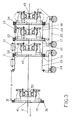
- FIG. 2 shows one of the lock devices 10, 10 'according to the present invention.
- the lock device 10, 10 ' consists of a plurality of individual locks 11, 12, 13, wherein in the embodiment according to FIG. 2 without restriction of generality three individual locks 11, 12, 13 are shown. In practice, more or fewer individual locks may be present; However, at least two individual locks connected in series before and at least two individual locks connected in series after the actual process area 3 according to FIG. 3 needed.
- Each of the individual locks 11, 12, 13 is formed and bounded by two lateral walls 15, 16, 17, 18 and a housing jacket 20, 21, 22 which connects the walls.
- the housing shells 20, 21, 22 are advantageously designed as circumferentially one-piece or multi-part.
- connections 31, 32, 33, 34 in the form of fastening means on the respective laterally adjacent walls 15, 16, 17, 18 releasably secured.
- Transport or processing rollers 50 can be seen for transporting or processing the strip material 2. These roles are exemplified in each case on a lateral wall 15, 16, 17, 18 attached.
- the strip material 2 is in FIG. 2 transported in the direction of the arrow.
- connection 31 of the first single lock 11 is open at the transition between the lateral wall 15 and the housing jacket 20.
- the lateral wall 15, together with the transport or processing rollers 50 fastened to it forms a first part of the first single lock 11.
- This first part can be mounted, for example, on the process area 3 which adjoins the left, that is to say in the transport direction of the belt 2 be worn by this.
- the housing shell 20 forms, together with the right side wall 16, a second part of the first single lock 11.
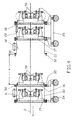
- the further individual locks 12 and 13 each with their transport and processing rollers 50 FIG.
- the second part of the first individual lock 11 as well as the further individual locks 12 and 13 fixedly connected thereto can be moved laterally in or against the transport direction of the strip material 2 by means of devices 24, 25; also in FIG. 3 the transport direction of the band is indicated by an arrow to the left.
- FIG. 3 is the second part with the associated further individual locks 12 and 13 to the path S relative to the stationary arranged first part of the single lock 12 against the transport direction of the belt procedure. Due to the separation of the two individual parts, the single lock 11 is opened and its interior and in particular the transport and processing rollers 50 are thus easily accessible, in particular for maintenance purposes.
- the band material 2 is guided through lock openings 41, 42, 43, 44, 45 in each of the lateral walls 15, 16, 17, 18. According to the invention, the displacement of the first part of the single lock relative to the second part of the single lock respectively along the strip material, that is, in or against the transport direction of the strip material, so that it does not have to be removed in the process of the two parts relative to each other.
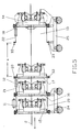
- FIG. 4 shows a second embodiment of the lock device according to the invention, wherein not the first single lock 11, but the second single lock 12 is opened by loosening the connection 32.
- the first part of the second individual lock is now formed from the lateral wall 16 and the transport and processing rollers 50 mounted thereon.
- the first lock of the second individual lock is associated with the individual lock 11 permanently mounted thereon, in particular with its housing jacket 20 and its left lateral wall 15.
- the second part of the second single lock is formed by its housing shell 21 and its right lateral wall 17.
- This second part is assigned the third single lock 13 with its housing shell 22, its right side wall 18 and with the attached to these two walls transport and / or processing rolls 50.
- both parts of the second single lock with their respective associated further individual locks independently movable. This is realized by associating the traversing device 24 with the first part of the second individual lock and the associated first individual lock 11, while the traversing device 25 is associated with the second part of the single lock and the associated further individual locks.
- the two parts of the second single lock 12 and their respectively associated further individual locks are moved by the path S against each other along the transport direction of the strip material 2.
- FIG. 5 shows a third embodiment of the lock device according to the invention, wherein, in contrast to FIG. 4 not the second, but the third single lock 13 was opened at the junction 33.
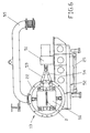
- FIG. 6 shows a cross section through one of the individual locks at the level of the transport or processing rollers 50 transversely to the transport direction of the strip material, which is perpendicular to the plane of the drawing.
- the Einzelzschleuse 13 with its housing shell 22, which is exemplified here tubular.
- the transport or processing rollers 50 can be seen, which are arranged above and below the strip material 2.
- These rollers can be driven via connecting shafts 53, 54 by a drive 51.
- Both the individual lock 13 and the drive 51 are arranged on a carrier unit 52, which can be moved by means of the device 25 in or against the transport direction of the belt.
- the drive 51 can also be arranged outside the carrying unit 52; then it is necessary that this is released from the transport or processing roles before the single lock is moved to the device 25.
- a pipe connection 55 is connected.
- This pipe connection is used for example as a suction device for generating a negative pressure or a vacuum in the interior of the single lock 13.
- This pipe connection is preferably designed so that it can be moved together with the single lock 13; then the pipe connection 55 does not need to be released from the housing shell 22 when the single lock 13 is to be moved.
- the connection between the pipe connection 55 and the housing shell 22 may also be made detachable; then the single lock 13 would be moved independently of the pipe connection 55 together with the other parts of the lock device 10, 10 possibly associated with it.
- An advantage of the lock device according to the invention is the possibility to open the individual locks and to move the parts or segments formed by the opening by means of the devices 24, 25 for displacing the same.
- the interior of the individual locks and in particular the transport or processing rollers therein may be accessible for maintenance purposes, for example.
- the opening of the individual locks need not be limited to a single lock, but can be done either gradually, that is temporally suggestive or at the same time in all individual locks the lock device. However, the more individual locks are to be opened at the same time, the more space is required.
Landscapes
- Chemical & Material Sciences (AREA)
- Organic Chemistry (AREA)
- Chemical Kinetics & Catalysis (AREA)
- Advancing Webs (AREA)
- Treatment Of Fiber Materials (AREA)
- Casings For Electric Apparatus (AREA)
- Barrages (AREA)
- Details Of Valves (AREA)
- Bending Of Plates, Rods, And Pipes (AREA)
- Automobile Manufacture Line, Endless Track Vehicle, Trailer (AREA)
- Paper (AREA)
- Physical Vapour Deposition (AREA)
- Package Frames And Binding Bands (AREA)
- Sliding Valves (AREA)
Abstract
Claims (14)
- Dispositif de passage (1, 4, 5, 10) comprenant au moins un sas individuel (11) que doit traverser une matière en forme de bande ;
caractérisé
en ce que le sas individuel (11) est constitué par au moins une première et une deuxième partie ;
en ce qu'on prévoit une liaison amovible entre la première et la deuxième partie pour l'ouverture et la fermeture du sas individuel ; et
en ce qu'on prévoit au moins un dispositif (24, 25) pour le déplacement de la première et de la deuxième partie du sas individuel (11) l'une par rapport à l'autre dans ou à l'encontre de la direction de transport de la matière en forme de bande (2) lorsque la liaison est ouverte. - Dispositif de passage (1, 4, 5, 10) selon la revendication 1,
caractérisé
en ce que le logement du sas individuel (11) est constitué par une première paroi latérale (16) comprenant une ouverture de passage (42) pour l'entrée de la matière en forme de bande (2) dans le sas individuel, par une deuxième paroi latérale (15) comportant une ouverture de passage (41) pour la sortie de la matière en forme de bande (2) hors du sas individuel (11), et par une enveloppe faisant office de logement (20) entre la première et la deuxième paroi (15). - Dispositif de passage (1, 4, 5, 10) selon la revendication 2,
caractérisé
en ce que la première partie du sas individuel (11) présente au moins une partie de la première paroi latérale (16) avec l'ouverture de passage (42) pour l'entrée de la matière en forme de bande (2) ; et en ce que la deuxième partie du sas individuel (11) présente au moins une partie de la deuxième paroi latérale (15) avec l'ouverture de passage (41) pour la sortie de la matière en forme de bande (2). - Dispositif de passage (1, 4, 5, 10) selon la revendication 2 ou 3,
caractérisé en ce que la première ou la deuxième partie ou encore les deux parties du sas individuel (11, 12, 13) présentent au moins une partie de l'enveloppe faisant office de logement (20). - Dispositif de passage (1, 4, 5, 10) selon l'une quelconque des revendications 2 à 4,
caractérisé
en ce que le sas individuel (11, 12, 13) présente des moyens de traitement ou de transport (50) pour la matière en forme de bande, comme par exemple des rouleaux de traitement ou de transport, et des entraînements (51) pour ces moyens, les moyens ou les entraînements étant fixés à la première ou à la deuxième paroi latérale (15, 16) ou encore à l'enveloppe (20) faisant office de logement ; et
en ce que ces moyens et ces entraînements - de préférence en fonction de la paroi latérale (15, 16) ou de l'enveloppe (20) faisant office de logement, à laquelle ils sont fixés - sont attribués à la première ou à la deuxième partie du sas individuel (11, 12, 13) et peuvent se déplacer avec ladite partie. - Dispositif de passage (1, 4, 5, 10) selon l'une quelconque des revendications 2 à 5,
caractérisé
en ce qu'on raccorde une liaison tubulaire (55) depuis l'extérieur à l'enveloppe (23) faisant office de logement pour le réglage d'une pression désirée à l'intérieur du sas individuel (11) ; et en ce que la liaison tubulaire (55) - en fonction de la partie de l'enveloppe faisant office de logement, à laquelle elle est raccordée - est attribuée soit à la première, soit à la deuxième partie du sas individuel (11, 12, 13) et peut se déplacer conjointement avec celle-ci. - Dispositif de passage (1, 4, 5, 10) selon l'une quelconque des revendications 2 à 5,
caractérisé
en ce qu'on raccorde une liaison tubulaire (55) depuis l'extérieur de manière amovible à l'enveloppe (23) faisant office de logement pour le réglage d'une pression désirée à l'intérieur du sas individuel ; et
en ce que la liaison tubulaire (55), lorsqu'elle est découplée de l'enveloppe (23) faisant office de logement, peut se déplacer indépendamment de la première ou de la deuxième partie du sas individuel (11, 12, 13) en particulier dans ou à l'encontre de la direction de transport de la matière en forme de bande (2). - Dispositif de passage (1, 4, 5, 10) selon l'une quelconque des revendications précédentes, caractérisé
en ce qu'on prévoit un premier dispositif (24) pour le déplacement, à des fins de déplacement de la première partie du sas individuel (11, 12, 13) et on prévoit un deuxième dispositif (25) pour le déplacement, à des fins de déplacement de la deuxième partie. - Dispositif de passage (1, 4, 5, 10) selon l'une quelconque des revendications précédentes, caractérisé
en ce que le dispositif (24, 25) pour le déplacement est réalisé sous la forme d'un châssis mobile ou sous la forme d'un mécanisme de glissement. - Dispositif de passage (1, 4, 5, 10) sous la forme d'une cascade de sas comprenant une multitude de sas individuels (11, 12, 13) montés les uns derrière les autres dans la direction de transport de la matière en forme de bande (2), au moins un des sas individuels (11) étant réalisé en deux parties comprenant une première et une deuxième partie, conformément à l'une quelconque des revendications précédentes, et dans lequel les autres sas individuels (12, 13) sont raccordés à la première ou à la deuxième partie du sas individuel en deux parties (11) et, de manière correspondante, sont attribués à la première ou à la deuxième partie et peuvent se déplacer conjointement avec celle-ci.
- Dispositif de passage (1, 4, 5, 10) selon la revendication 10,
caractérisé
en ce que deux sas individuels voisins (11, 12) présentent une paroi latérale commune (16) comportant une ouverture de passage (42) pour le transfert de la matière en forme de bande (2) d'un sas individuel (12) à l'autre. - Procédé pour l'ouverture d'un dispositif de passage (1, 4, 5, 10) comprenant au moins un sas individuel (11) que doit traverser une matière en forme de bande ;
caractérisé par les étapes suivantes consistant à :ouvrir le sas individuel (11) par suppression d'une liaison entre une première et une deuxième partie du sas individuel ; etdéplacer la première et la deuxième partie du sas individuel (11) l'une par rapport à l'autre dans ouà l'encontre de la direction de transport de la matière en forme de bande (2). - Procédé selon la revendication 12,
caractérisé
en ce que la première partie du sas individuel (11) présente au moins une partie de la première paroi latérale (16) avec l'ouverture de passage (42) pour l'entrée de la matière en forme de bande (2) ; en ce que la deuxième partie du sas individuel (11) présente au moins une partie de la deuxième paroi latérale (15) avec l'ouverture de passage (41) pour la sortie de la matière en forme de bande (2) ; et en ce qu'on déplace la première et/ou la deuxième partie du sas individuel (11, 12, 13), lors de l'ouverture et de la fermeture du sas individuel (11, 12, 13) le long de la matière en forme de bande (2), tandis que la matière en forme de bande (2) est guidée à travers les ouvertures de passage. - Procédé selon la revendication 12 ou 13, caractérisé
en ce que la première et la deuxième partie du sas individuel (11), une fois que les travaux d'entretien sont terminés, sont à nouveau déplacées de manière conjointe le long de la matière en forme de bande (2) et sont à nouveau reliées l'une à l'autre.
Priority Applications (1)
| Application Number | Priority Date | Filing Date | Title |
|---|---|---|---|
| PL08839183T PL2205347T3 (pl) | 2007-10-17 | 2008-10-11 | Urządzenie śluzowe i sposób jego otwierania |
Applications Claiming Priority (2)
| Application Number | Priority Date | Filing Date | Title |
|---|---|---|---|
| DE102007049669A DE102007049669A1 (de) | 2007-10-17 | 2007-10-17 | Schleusenvorrichtung und Verfahren zum Öffnen der Schleusenvorrichtung |
| PCT/EP2008/010773 WO2009049921A1 (fr) | 2007-10-17 | 2008-10-11 | Système de sas et procédé pour ouvrir un système de sas |
Publications (2)
| Publication Number | Publication Date |
|---|---|
| EP2205347A1 EP2205347A1 (fr) | 2010-07-14 |
| EP2205347B1 true EP2205347B1 (fr) | 2011-08-03 |
Family
ID=40394017
Family Applications (1)
| Application Number | Title | Priority Date | Filing Date |
|---|---|---|---|
| EP08839183A Not-in-force EP2205347B1 (fr) | 2007-10-17 | 2008-10-11 | Système de sas et procédé pour ouvrir un système de sas |
Country Status (21)
| Country | Link |
|---|---|
| US (1) | US20110038693A1 (fr) |
| EP (1) | EP2205347B1 (fr) |
| JP (1) | JP5171960B2 (fr) |
| KR (1) | KR101151249B1 (fr) |
| CN (1) | CN101827646B (fr) |
| AR (1) | AR068928A1 (fr) |
| AT (1) | ATE518585T1 (fr) |
| AU (1) | AU2008314055B2 (fr) |
| CA (1) | CA2698323C (fr) |
| CO (1) | CO6260110A2 (fr) |
| DE (1) | DE102007049669A1 (fr) |
| EG (1) | EG25434A (fr) |
| ES (1) | ES2367552T3 (fr) |
| MX (1) | MX2010004189A (fr) |
| PL (1) | PL2205347T3 (fr) |
| RS (1) | RS20100167A (fr) |
| RU (1) | RU2433861C1 (fr) |
| TW (1) | TWI346573B (fr) |
| UA (1) | UA96856C2 (fr) |
| WO (1) | WO2009049921A1 (fr) |
| ZA (1) | ZA201001494B (fr) |
Families Citing this family (1)
| Publication number | Priority date | Publication date | Assignee | Title |
|---|---|---|---|---|
| ES2703825T3 (es) * | 2015-07-20 | 2019-03-12 | Staeubli Sargans Ag | Máquina de disposición de hilos |
Family Cites Families (10)
| Publication number | Priority date | Publication date | Assignee | Title |
|---|---|---|---|---|
| US4113182A (en) * | 1977-03-18 | 1978-09-12 | Brago Reacelyn A | Multi-fluid wash system |
| US4812101A (en) * | 1987-04-27 | 1989-03-14 | American Telephone And Telegraph Company, At&T Bell Laboratories | Method and apparatus for continuous throughput in a vacuum environment |
| DE8915647U1 (fr) * | 1989-03-21 | 1990-12-13 | Reinbold, Heinz, Dipl.-Ing., 5200 Siegburg, De | |
| JPH07207445A (ja) * | 1994-01-20 | 1995-08-08 | Kawasaki Steel Corp | 差圧装置 |
| DE19753656C1 (de) * | 1997-12-03 | 1998-12-03 | Fraunhofer Ges Forschung | Einrichtung zur Vakuumbeschichtung von Gleitlagern |
| DE19960751A1 (de) * | 1999-12-16 | 2001-07-05 | Fzm Ges Fuer Produktentwicklun | Schleuse und Verfahren zur Anwendung derselben |
| EP1479789A1 (fr) * | 2003-05-23 | 2004-11-24 | Recherche Et Developpement Du Groupe Cockerill Sambre | Sas d'étanchéité pour ligne de dépôt sous vide sur produit plat |
| DE102004007831A1 (de) * | 2004-02-18 | 2005-09-01 | Sms Demag Ag | Verfahren und Einrichtung zum Wechseln von Walzensätzen in Walzgerüsten einer Walzstraße |
| DE102007009710A1 (de) | 2006-10-27 | 2008-04-30 | Sms Demag Ag | Bandschleuse |
| DE102007009992A1 (de) | 2006-10-27 | 2008-04-30 | Sms Demag Ag | Bandschleuse |
-
2007
- 2007-10-17 DE DE102007049669A patent/DE102007049669A1/de not_active Withdrawn
-
2008
- 2008-10-11 ES ES08839183T patent/ES2367552T3/es active Active
- 2008-10-11 KR KR1020107006681A patent/KR101151249B1/ko not_active IP Right Cessation
- 2008-10-11 RS RS20100167A patent/RS20100167A/en unknown
- 2008-10-11 EP EP08839183A patent/EP2205347B1/fr not_active Not-in-force
- 2008-10-11 CN CN2008801118785A patent/CN101827646B/zh not_active Expired - Fee Related
- 2008-10-11 WO PCT/EP2008/010773 patent/WO2009049921A1/fr active Application Filing
- 2008-10-11 US US12/734,184 patent/US20110038693A1/en not_active Abandoned
- 2008-10-11 CA CA2698323A patent/CA2698323C/fr not_active Expired - Fee Related
- 2008-10-11 UA UAA201005858A patent/UA96856C2/ru unknown
- 2008-10-11 AT AT08839183T patent/ATE518585T1/de active
- 2008-10-11 MX MX2010004189A patent/MX2010004189A/es not_active Application Discontinuation
- 2008-10-11 RU RU2010119493/05A patent/RU2433861C1/ru not_active IP Right Cessation
- 2008-10-11 AU AU2008314055A patent/AU2008314055B2/en not_active Ceased
- 2008-10-11 PL PL08839183T patent/PL2205347T3/pl unknown
- 2008-10-11 JP JP2010528331A patent/JP5171960B2/ja not_active Expired - Fee Related
- 2008-10-17 TW TW097139818A patent/TWI346573B/zh not_active IP Right Cessation
- 2008-10-17 AR ARP080104558A patent/AR068928A1/es active IP Right Grant
-
2010
- 2010-03-02 ZA ZA201001494A patent/ZA201001494B/xx unknown
- 2010-03-09 EG EG2010030382A patent/EG25434A/xx active
- 2010-03-12 CO CO10029649A patent/CO6260110A2/es not_active Application Discontinuation
Also Published As
| Publication number | Publication date |
|---|---|
| CN101827646A (zh) | 2010-09-08 |
| RS20100167A (en) | 2011-08-31 |
| KR20100059914A (ko) | 2010-06-04 |
| ATE518585T1 (de) | 2011-08-15 |
| UA96856C2 (ru) | 2011-12-12 |
| EG25434A (en) | 2012-01-05 |
| US20110038693A1 (en) | 2011-02-17 |
| CN101827646B (zh) | 2012-11-28 |
| JP5171960B2 (ja) | 2013-03-27 |
| RU2433861C1 (ru) | 2011-11-20 |
| EP2205347A1 (fr) | 2010-07-14 |
| TW200936270A (en) | 2009-09-01 |
| ZA201001494B (en) | 2010-10-27 |
| AU2008314055A1 (en) | 2009-04-23 |
| PL2205347T3 (pl) | 2011-12-30 |
| CA2698323A1 (fr) | 2009-04-23 |
| CO6260110A2 (es) | 2011-03-22 |
| KR101151249B1 (ko) | 2012-06-14 |
| ES2367552T3 (es) | 2011-11-04 |
| WO2009049921A1 (fr) | 2009-04-23 |
| TWI346573B (en) | 2011-08-11 |
| CA2698323C (fr) | 2012-02-07 |
| MX2010004189A (es) | 2010-05-14 |
| DE102007049669A1 (de) | 2009-04-23 |
| AU2008314055B2 (en) | 2011-03-10 |
| JP2010540244A (ja) | 2010-12-24 |
| AR068928A1 (es) | 2009-12-16 |
Similar Documents
| Publication | Publication Date | Title |
|---|---|---|
| EP3166696B1 (fr) | Dispositif de fourniture d'une transition | |
| DE2306538A1 (de) | Betaetigungsvorrichtung | |
| EP3017111A1 (fr) | Tambour de séchage à grand cylindre et procédé de fabrication d'un tambour de séchage à grand cylindre | |
| EP0910541B1 (fr) | Systeme d'etancheite pour clapet de fermeture d'un orifice de passage | |
| EP3184444A1 (fr) | Dispositif et procédé de rétrécissement de matériaux d'emballage thermoplastiques plats sur un article ou sur des ensembles d'articles | |
| EP2424687A1 (fr) | Rampe de pulvérisation, section et procédé pour appliquer un fluide sur un produit | |
| EP2205347B1 (fr) | Système de sas et procédé pour ouvrir un système de sas | |
| DE102010042777A1 (de) | Laserschneidanordnung und Verfahren zum Schneiden | |
| EP2975309A1 (fr) | Joint de compression doté d'un corps élastomère | |
| EP2439474B1 (fr) | Dispositif de séchage d'un élément de machine doté d'une chambre sèche sous vide | |
| EP1580446B1 (fr) | Procédé d'opération d'un appareil à vide avec variation de pression | |
| DE3050419T1 (fr) | ||
| EP3888799A1 (fr) | Dispositif de fermeture d'au moins une ouverture lors du changement d'au moins un élément filtrant dans une installation de filtre à air d'échappement et installation de peinture pourvu d'un tel dispositif | |
| EP3707450B1 (fr) | Robinet-vanne | |
| EP1283154A2 (fr) | Procédé pour le montage d'une porte dans un cadre de porte d'une carrosserie de véhicule , et son appareil de montage | |
| EP2984204B1 (fr) | Dispositif de traitement de substrats flexibles | |
| DE19934557A1 (de) | Vorrichtung zum Kühlen von auf einer Förderstrecke geförderten Metallbändern oder -blechen | |
| EP4015060B1 (fr) | Dispositifs et procédé de nettoyage des plaques filtrantes d'un paquet filtrant, installations de filtration et procédé de mise à niveau des installation de filtration | |
| DE4005823A1 (de) | Knetmaschine mit wenigstens zwei nebeneinander angeordneten knetkammern | |
| DE102019119818B4 (de) | Unterdruck-Zuführeinrichtung | |
| DE19543266A1 (de) | Einrichtung zur Mikrowellenbeaufschlagung von Materialien oder Stückgütern | |
| DE2220244A1 (de) | Vorrichtung, in der ein Unterdruck herrscht oder die mit einer speziellen Atmosphäre gefüllt ist, und durch die längliche Materialien hindurchgeführt werden | |
| DE60201747T2 (de) | Vorrichtung zum eintragen von weichelastischen bändern in eine kammer | |
| EP2309214A2 (fr) | Procédé et tunnel de refroidissement pour refroidir des produits | |
| DE102014117065A1 (de) | Vorrichtung und Verfahren zur Herstellung eines Faserverbundwerkstücks |
Legal Events
| Date | Code | Title | Description |
|---|---|---|---|
| PUAI | Public reference made under article 153(3) epc to a published international application that has entered the european phase |
Free format text: ORIGINAL CODE: 0009012 |
|
| 17P | Request for examination filed |
Effective date: 20100517 |
|
| AK | Designated contracting states |
Kind code of ref document: A1 Designated state(s): AT BE BG CH CY CZ DE DK EE ES FI FR GB GR HR HU IE IS IT LI LT LU LV MC MT NL NO PL PT RO SE SI SK TR |
|
| AX | Request for extension of the european patent |
Extension state: AL BA MK RS |
|
| DAX | Request for extension of the european patent (deleted) | ||
| GRAP | Despatch of communication of intention to grant a patent |
Free format text: ORIGINAL CODE: EPIDOSNIGR1 |
|
| GRAS | Grant fee paid |
Free format text: ORIGINAL CODE: EPIDOSNIGR3 |
|
| GRAA | (expected) grant |
Free format text: ORIGINAL CODE: 0009210 |
|
| AK | Designated contracting states |
Kind code of ref document: B1 Designated state(s): AT BE BG CH CY CZ DE DK EE ES FI FR GB GR HR HU IE IS IT LI LT LU LV MC MT NL NO PL PT RO SE SI SK TR |
|
| REG | Reference to a national code |
Ref country code: GB Ref legal event code: FG4D Free format text: NOT ENGLISH |
|
| REG | Reference to a national code |
Ref country code: CH Ref legal event code: NV Representative=s name: SCHMAUDER & PARTNER AG PATENT- UND MARKENANWAELTE Ref country code: CH Ref legal event code: EP |
|
| REG | Reference to a national code |
Ref country code: IE Ref legal event code: FG4D Free format text: LANGUAGE OF EP DOCUMENT: GERMAN |
|
| REG | Reference to a national code |
Ref country code: DE Ref legal event code: R096 Ref document number: 502008004431 Country of ref document: DE Effective date: 20110929 |
|
| REG | Reference to a national code |
Ref country code: SE Ref legal event code: TRGR |
|
| REG | Reference to a national code |
Ref country code: ES Ref legal event code: FG2A Ref document number: 2367552 Country of ref document: ES Kind code of ref document: T3 Effective date: 20111104 |
|
| REG | Reference to a national code |
Ref country code: NL Ref legal event code: T3 |
|
| REG | Reference to a national code |
Ref country code: PL Ref legal event code: T3 |
|
| LTIE | Lt: invalidation of european patent or patent extension |
Effective date: 20110803 |
|
| PG25 | Lapsed in a contracting state [announced via postgrant information from national office to epo] |
Ref country code: LT Free format text: LAPSE BECAUSE OF FAILURE TO SUBMIT A TRANSLATION OF THE DESCRIPTION OR TO PAY THE FEE WITHIN THE PRESCRIBED TIME-LIMIT Effective date: 20110803 Ref country code: PT Free format text: LAPSE BECAUSE OF FAILURE TO SUBMIT A TRANSLATION OF THE DESCRIPTION OR TO PAY THE FEE WITHIN THE PRESCRIBED TIME-LIMIT Effective date: 20111205 Ref country code: IS Free format text: LAPSE BECAUSE OF FAILURE TO SUBMIT A TRANSLATION OF THE DESCRIPTION OR TO PAY THE FEE WITHIN THE PRESCRIBED TIME-LIMIT Effective date: 20111203 Ref country code: NO Free format text: LAPSE BECAUSE OF FAILURE TO SUBMIT A TRANSLATION OF THE DESCRIPTION OR TO PAY THE FEE WITHIN THE PRESCRIBED TIME-LIMIT Effective date: 20111103 Ref country code: HR Free format text: LAPSE BECAUSE OF FAILURE TO SUBMIT A TRANSLATION OF THE DESCRIPTION OR TO PAY THE FEE WITHIN THE PRESCRIBED TIME-LIMIT Effective date: 20110803 |
|
| PGFP | Annual fee paid to national office [announced via postgrant information from national office to epo] |
Ref country code: CZ Payment date: 20111005 Year of fee payment: 4 Ref country code: ES Payment date: 20111026 Year of fee payment: 4 Ref country code: FI Payment date: 20111013 Year of fee payment: 4 Ref country code: SE Payment date: 20111021 Year of fee payment: 4 Ref country code: NL Payment date: 20111025 Year of fee payment: 4 |
|
| PG25 | Lapsed in a contracting state [announced via postgrant information from national office to epo] |
Ref country code: GR Free format text: LAPSE BECAUSE OF FAILURE TO SUBMIT A TRANSLATION OF THE DESCRIPTION OR TO PAY THE FEE WITHIN THE PRESCRIBED TIME-LIMIT Effective date: 20111104 Ref country code: CY Free format text: LAPSE BECAUSE OF FAILURE TO SUBMIT A TRANSLATION OF THE DESCRIPTION OR TO PAY THE FEE WITHIN THE PRESCRIBED TIME-LIMIT Effective date: 20110803 Ref country code: SI Free format text: LAPSE BECAUSE OF FAILURE TO SUBMIT A TRANSLATION OF THE DESCRIPTION OR TO PAY THE FEE WITHIN THE PRESCRIBED TIME-LIMIT Effective date: 20110803 Ref country code: LV Free format text: LAPSE BECAUSE OF FAILURE TO SUBMIT A TRANSLATION OF THE DESCRIPTION OR TO PAY THE FEE WITHIN THE PRESCRIBED TIME-LIMIT Effective date: 20110803 |
|
| REG | Reference to a national code |
Ref country code: IE Ref legal event code: FD4D |
|
| PG25 | Lapsed in a contracting state [announced via postgrant information from national office to epo] |
Ref country code: SK Free format text: LAPSE BECAUSE OF FAILURE TO SUBMIT A TRANSLATION OF THE DESCRIPTION OR TO PAY THE FEE WITHIN THE PRESCRIBED TIME-LIMIT Effective date: 20110803 Ref country code: IE Free format text: LAPSE BECAUSE OF FAILURE TO SUBMIT A TRANSLATION OF THE DESCRIPTION OR TO PAY THE FEE WITHIN THE PRESCRIBED TIME-LIMIT Effective date: 20110803 |
|
| PG25 | Lapsed in a contracting state [announced via postgrant information from national office to epo] |
Ref country code: RO Free format text: LAPSE BECAUSE OF FAILURE TO SUBMIT A TRANSLATION OF THE DESCRIPTION OR TO PAY THE FEE WITHIN THE PRESCRIBED TIME-LIMIT Effective date: 20110803 Ref country code: EE Free format text: LAPSE BECAUSE OF FAILURE TO SUBMIT A TRANSLATION OF THE DESCRIPTION OR TO PAY THE FEE WITHIN THE PRESCRIBED TIME-LIMIT Effective date: 20110803 Ref country code: MC Free format text: LAPSE BECAUSE OF NON-PAYMENT OF DUE FEES Effective date: 20111031 |
|
| PLBE | No opposition filed within time limit |
Free format text: ORIGINAL CODE: 0009261 |
|
| STAA | Information on the status of an ep patent application or granted ep patent |
Free format text: STATUS: NO OPPOSITION FILED WITHIN TIME LIMIT |
|
| PG25 | Lapsed in a contracting state [announced via postgrant information from national office to epo] |
Ref country code: DK Free format text: LAPSE BECAUSE OF FAILURE TO SUBMIT A TRANSLATION OF THE DESCRIPTION OR TO PAY THE FEE WITHIN THE PRESCRIBED TIME-LIMIT Effective date: 20110803 |
|
| 26N | No opposition filed |
Effective date: 20120504 |
|
| REG | Reference to a national code |
Ref country code: DE Ref legal event code: R097 Ref document number: 502008004431 Country of ref document: DE Effective date: 20120504 |
|
| PGFP | Annual fee paid to national office [announced via postgrant information from national office to epo] |
Ref country code: BE Payment date: 20121022 Year of fee payment: 5 Ref country code: FR Payment date: 20121031 Year of fee payment: 5 Ref country code: DE Payment date: 20121023 Year of fee payment: 5 |
|
| PG25 | Lapsed in a contracting state [announced via postgrant information from national office to epo] |
Ref country code: MT Free format text: LAPSE BECAUSE OF FAILURE TO SUBMIT A TRANSLATION OF THE DESCRIPTION OR TO PAY THE FEE WITHIN THE PRESCRIBED TIME-LIMIT Effective date: 20110803 |
|
| PGFP | Annual fee paid to national office [announced via postgrant information from national office to epo] |
Ref country code: IT Payment date: 20121023 Year of fee payment: 5 |
|
| REG | Reference to a national code |
Ref country code: NL Ref legal event code: V1 Effective date: 20130501 |
|
| PG25 | Lapsed in a contracting state [announced via postgrant information from national office to epo] |
Ref country code: LU Free format text: LAPSE BECAUSE OF NON-PAYMENT OF DUE FEES Effective date: 20111011 |
|
| REG | Reference to a national code |
Ref country code: CH Ref legal event code: PL |
|
| GBPC | Gb: european patent ceased through non-payment of renewal fee |
Effective date: 20121011 |
|
| PG25 | Lapsed in a contracting state [announced via postgrant information from national office to epo] |
Ref country code: BG Free format text: LAPSE BECAUSE OF FAILURE TO SUBMIT A TRANSLATION OF THE DESCRIPTION OR TO PAY THE FEE WITHIN THE PRESCRIBED TIME-LIMIT Effective date: 20111103 |
|
| PG25 | Lapsed in a contracting state [announced via postgrant information from national office to epo] |
Ref country code: CZ Free format text: LAPSE BECAUSE OF NON-PAYMENT OF DUE FEES Effective date: 20121011 Ref country code: GB Free format text: LAPSE BECAUSE OF NON-PAYMENT OF DUE FEES Effective date: 20121011 Ref country code: LI Free format text: LAPSE BECAUSE OF NON-PAYMENT OF DUE FEES Effective date: 20121031 Ref country code: CH Free format text: LAPSE BECAUSE OF NON-PAYMENT OF DUE FEES Effective date: 20121031 Ref country code: SE Free format text: LAPSE BECAUSE OF NON-PAYMENT OF DUE FEES Effective date: 20121012 |
|
| PG25 | Lapsed in a contracting state [announced via postgrant information from national office to epo] |
Ref country code: NL Free format text: LAPSE BECAUSE OF NON-PAYMENT OF DUE FEES Effective date: 20130501 Ref country code: FI Free format text: LAPSE BECAUSE OF NON-PAYMENT OF DUE FEES Effective date: 20121011 |
|
| PG25 | Lapsed in a contracting state [announced via postgrant information from national office to epo] |
Ref country code: TR Free format text: LAPSE BECAUSE OF FAILURE TO SUBMIT A TRANSLATION OF THE DESCRIPTION OR TO PAY THE FEE WITHIN THE PRESCRIBED TIME-LIMIT Effective date: 20110803 |
|
| PG25 | Lapsed in a contracting state [announced via postgrant information from national office to epo] |
Ref country code: HU Free format text: LAPSE BECAUSE OF FAILURE TO SUBMIT A TRANSLATION OF THE DESCRIPTION OR TO PAY THE FEE WITHIN THE PRESCRIBED TIME-LIMIT Effective date: 20110803 |
|
| REG | Reference to a national code |
Ref country code: ES Ref legal event code: FD2A Effective date: 20140115 |
|
| PG25 | Lapsed in a contracting state [announced via postgrant information from national office to epo] |
Ref country code: PL Free format text: LAPSE BECAUSE OF NON-PAYMENT OF DUE FEES Effective date: 20121011 Ref country code: ES Free format text: LAPSE BECAUSE OF NON-PAYMENT OF DUE FEES Effective date: 20121012 |
|
| BERE | Be: lapsed |
Owner name: SMS SIEMAG AG Effective date: 20131031 |
|
| REG | Reference to a national code |
Ref country code: DE Ref legal event code: R119 Ref document number: 502008004431 Country of ref document: DE |
|
| REG | Reference to a national code |
Ref country code: FR Ref legal event code: ST Effective date: 20140630 |
|
| PG25 | Lapsed in a contracting state [announced via postgrant information from national office to epo] |
Ref country code: IT Free format text: LAPSE BECAUSE OF NON-PAYMENT OF DUE FEES Effective date: 20131011 Ref country code: FR Free format text: LAPSE BECAUSE OF NON-PAYMENT OF DUE FEES Effective date: 20131031 |
|
| PG25 | Lapsed in a contracting state [announced via postgrant information from national office to epo] |
Ref country code: BE Free format text: LAPSE BECAUSE OF NON-PAYMENT OF DUE FEES Effective date: 20131031 |
|
| PG25 | Lapsed in a contracting state [announced via postgrant information from national office to epo] |
Ref country code: DE Free format text: LAPSE BECAUSE OF NON-PAYMENT OF DUE FEES Effective date: 20140501 |
|
| REG | Reference to a national code |
Ref country code: DE Ref legal event code: R119 Ref document number: 502008004431 Country of ref document: DE Effective date: 20140501 |
|
| REG | Reference to a national code |
Ref country code: AT Ref legal event code: MM01 Ref document number: 518585 Country of ref document: AT Kind code of ref document: T Effective date: 20131011 |
|
| PG25 | Lapsed in a contracting state [announced via postgrant information from national office to epo] |
Ref country code: AT Free format text: LAPSE BECAUSE OF NON-PAYMENT OF DUE FEES Effective date: 20131011 |