EP2204576B1 - Longeron pour une pale de rotor d'éolienne et procédé de fabrication de pale de rotor d'éolienne - Google Patents
Longeron pour une pale de rotor d'éolienne et procédé de fabrication de pale de rotor d'éolienne Download PDFInfo
- Publication number
- EP2204576B1 EP2204576B1 EP09177438.0A EP09177438A EP2204576B1 EP 2204576 B1 EP2204576 B1 EP 2204576B1 EP 09177438 A EP09177438 A EP 09177438A EP 2204576 B1 EP2204576 B1 EP 2204576B1
- Authority
- EP
- European Patent Office
- Prior art keywords
- rotor blade
- sparcap
- carbon material
- material layer
- wind turbine
- Prior art date
- Legal status (The legal status is an assumption and is not a legal conclusion. Google has not performed a legal analysis and makes no representation as to the accuracy of the status listed.)
- Not-in-force
Links
- 238000004519 manufacturing process Methods 0.000 title description 6
- 239000003575 carbonaceous material Substances 0.000 claims description 78
- 239000011162 core material Substances 0.000 claims description 49
- 229920000049 Carbon (fiber) Polymers 0.000 claims description 10
- 239000004917 carbon fiber Substances 0.000 claims description 10
- 239000000463 material Substances 0.000 claims description 9
- VNWKTOKETHGBQD-UHFFFAOYSA-N methane Chemical compound C VNWKTOKETHGBQD-UHFFFAOYSA-N 0.000 claims description 5
- 239000002023 wood Substances 0.000 claims description 4
- 239000011159 matrix material Substances 0.000 claims description 3
- 239000006261 foam material Substances 0.000 claims description 2
- OKTJSMMVPCPJKN-UHFFFAOYSA-N Carbon Chemical compound [C] OKTJSMMVPCPJKN-UHFFFAOYSA-N 0.000 description 8
- 229910052799 carbon Inorganic materials 0.000 description 8
- 230000002457 bidirectional effect Effects 0.000 description 4
- 239000000835 fiber Substances 0.000 description 4
- 238000000034 method Methods 0.000 description 3
- 239000011347 resin Substances 0.000 description 3
- 229920005989 resin Polymers 0.000 description 3
- 238000005452 bending Methods 0.000 description 2
- 229920002430 Fibre-reinforced plastic Polymers 0.000 description 1
- 240000007182 Ochroma pyramidale Species 0.000 description 1
- 241000218657 Picea Species 0.000 description 1
- 239000000853 adhesive Substances 0.000 description 1
- 230000001070 adhesive effect Effects 0.000 description 1
- 230000009286 beneficial effect Effects 0.000 description 1
- 230000003247 decreasing effect Effects 0.000 description 1
- 239000011151 fibre-reinforced plastic Substances 0.000 description 1
- 239000006260 foam Substances 0.000 description 1
Images


Classifications
-
- F—MECHANICAL ENGINEERING; LIGHTING; HEATING; WEAPONS; BLASTING
- F03—MACHINES OR ENGINES FOR LIQUIDS; WIND, SPRING, OR WEIGHT MOTORS; PRODUCING MECHANICAL POWER OR A REACTIVE PROPULSIVE THRUST, NOT OTHERWISE PROVIDED FOR
- F03D—WIND MOTORS
- F03D1/00—Wind motors with rotation axis substantially parallel to the air flow entering the rotor
- F03D1/06—Rotors
- F03D1/065—Rotors characterised by their construction elements
- F03D1/0675—Rotors characterised by their construction elements of the blades
-
- F—MECHANICAL ENGINEERING; LIGHTING; HEATING; WEAPONS; BLASTING
- F05—INDEXING SCHEMES RELATING TO ENGINES OR PUMPS IN VARIOUS SUBCLASSES OF CLASSES F01-F04
- F05B—INDEXING SCHEME RELATING TO WIND, SPRING, WEIGHT, INERTIA OR LIKE MOTORS, TO MACHINES OR ENGINES FOR LIQUIDS COVERED BY SUBCLASSES F03B, F03D AND F03G
- F05B2240/00—Components
- F05B2240/20—Rotors
- F05B2240/30—Characteristics of rotor blades, i.e. of any element transforming dynamic fluid energy to or from rotational energy and being attached to a rotor
- F05B2240/301—Cross-section characteristics
-
- Y—GENERAL TAGGING OF NEW TECHNOLOGICAL DEVELOPMENTS; GENERAL TAGGING OF CROSS-SECTIONAL TECHNOLOGIES SPANNING OVER SEVERAL SECTIONS OF THE IPC; TECHNICAL SUBJECTS COVERED BY FORMER USPC CROSS-REFERENCE ART COLLECTIONS [XRACs] AND DIGESTS
- Y02—TECHNOLOGIES OR APPLICATIONS FOR MITIGATION OR ADAPTATION AGAINST CLIMATE CHANGE
- Y02E—REDUCTION OF GREENHOUSE GAS [GHG] EMISSIONS, RELATED TO ENERGY GENERATION, TRANSMISSION OR DISTRIBUTION
- Y02E10/00—Energy generation through renewable energy sources
- Y02E10/70—Wind energy
- Y02E10/72—Wind turbines with rotation axis in wind direction
-
- Y—GENERAL TAGGING OF NEW TECHNOLOGICAL DEVELOPMENTS; GENERAL TAGGING OF CROSS-SECTIONAL TECHNOLOGIES SPANNING OVER SEVERAL SECTIONS OF THE IPC; TECHNICAL SUBJECTS COVERED BY FORMER USPC CROSS-REFERENCE ART COLLECTIONS [XRACs] AND DIGESTS
- Y10—TECHNICAL SUBJECTS COVERED BY FORMER USPC
- Y10T—TECHNICAL SUBJECTS COVERED BY FORMER US CLASSIFICATION
- Y10T29/00—Metal working
- Y10T29/49—Method of mechanical manufacture
- Y10T29/49316—Impeller making
- Y10T29/49336—Blade making
- Y10T29/49337—Composite blade
-
- Y—GENERAL TAGGING OF NEW TECHNOLOGICAL DEVELOPMENTS; GENERAL TAGGING OF CROSS-SECTIONAL TECHNOLOGIES SPANNING OVER SEVERAL SECTIONS OF THE IPC; TECHNICAL SUBJECTS COVERED BY FORMER USPC CROSS-REFERENCE ART COLLECTIONS [XRACs] AND DIGESTS
- Y10—TECHNICAL SUBJECTS COVERED BY FORMER USPC
- Y10T—TECHNICAL SUBJECTS COVERED BY FORMER US CLASSIFICATION
- Y10T29/00—Metal working
- Y10T29/49—Method of mechanical manufacture
- Y10T29/49316—Impeller making
- Y10T29/49336—Blade making
- Y10T29/49339—Hollow blade
Definitions
- the embodiments described herein relate generally to a wind turbine rotor blade and, more particularly, to a sparcap for a wind turbine rotor blade.
- Wind turbine blades typically include two blade shell portions of fiber reinforced polymer. The blade shell portions are molded and then coupled together along cooperating edges using a suitable adhesive material. At least some turbine blades include one or more bracings that are adhesively coupled to an inner surface of a first blade shell portion. A cooperating second blade shell portion is then arranged on top of the bracings and adhesively coupled to the first blade shell portion along its edges.
- the blade shell portions are typically made using suitable evenly distributed fibers, fiber bundles, or mats of fibers layered in a mold part.
- the blade shell portions are relatively light and have only low rigidity. Therefore, a stiffness and a rigidity, as well as a buckling strength, of the blade shell portions may not withstand the loads and forces exerted on the rotor blade during operation.
- the blade shell portions are reinforced by sparcaps laminated to the inner surface of the blade shell portions.
- Flapwise loads which cause the rotor blade tip to deflect towards the wind turbine tower, are transferred along the rotor blade predominantly through the sparcaps.
- At least some conventional rotor blades include sparcaps fabricated from a suitable carbon material. The stiffness requirements of the conventional wind turbine rotor blade designs may be met by a completely carbon sparcap, but with an undesirable mass and/or cost penalty.
- WO2008092451 A2 discloses a blade for a wind turbine, particularly to a blade that may be produced by an advanced manufacturing process for producing a blade with high quality structural components.
- EP1965074 A2 discloses a wind turbine blade comprising at least one central spar longitudinal section composed of two cap prefabricated panels and two web prefabricated panels placed side by side in a box shape and at least two shell longitudinal sections forming, respectively, the leading edge and the trailing edge of the corresponding blade section that are placed adjacently to a central spar section and are composed of a single prefabricated panel or of two prefabricated panels, the aerodynamic profile of the blade being defined by said cap panels and said single shell panels or said two shell panels.
- a sparcap for a wind turbine rotor blade according to appended claim 1 is provided.
- a rotor blade for a wind turbine according to appended claim 9 is provided.
- the embodiments described herein provide a rotor blade for a wind turbine that includes a suitable sparcap for providing sufficient strength to the rotor blade while decreasing an overall weight of the rotor blade and/or fabrication cost.
- Efficient utilization of a carbon material, such as carbon fibers or a carbon fiber reinforced matrix, and a core material, such as a foam or suitable wood material, for fabrication of the sparcap produces a lighter and cost-effective rotor blade.
- a core material in the sparcap having a higher compressive strength and a lower density than a carbon material increases a buckling stiffness of the sparcap without significantly increasing a mass of the sparcap and/or a fabrication cost for the sparcap.
- the core material is positioned at one or more regions in the rotor blade susceptible to buckling forces. With appropriate use of both materials, rotor blade design requirements are met with a minimal material consumption and a minimal increase in rotor blade mass.
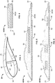
- FIG. 1 is a schematic view of a wind turbine 10.
- Wind turbine 10 includes a tower 12 to which a machine nacelle 14 is mounted at a first or top end portion.
- FIG. 2 is a schematic view of an exemplary configuration of rotor blade 18.
- Rotor blade 18 includes a first end or root section 20 configured to facilitate mounting rotor blade 18 to hub 16 and a second or tip end 22 opposing root section 20.
- a body 24 of rotor blade 18 extends between root section 20 and tip end 22.
- rotor blade 18 includes a first blade section 26, such as a suction side blade section, and an opposing second blade section 28, such as a pressure side blade section, coupled to first blade section 26 to form rotor blade 18.
- a suction side sparcap (not shown in Figure 2 ) is provided at an inner surface of the suction side rotor blade shell and/or a pressure side sparcap (not shown in Figure 2 ) is provided at an inner surface of the pressure side rotor blade shell.
- the suction side sparcap and/or the pressure side sparcap extend almost the full longitudinal length of rotor blade 18. However, shorter sparcaps may be used in alternative embodiments.
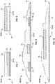
- FIG 3 is a cross-sectional view of an exemplary body 24 of rotor blade 18 along sectional line 3-3 in Figure 2 .
- first blade section 26 such as a suction side blade section
- second blade section 28 such as a pressure side blade section
- first blade section 26 and second blade section 28 are coupled at a leading edge 30 and an opposing trailing edge 32 of rotor blade 18.
- first sparcap 40 is positioned on and coupled to an inner surface 42 of first blade section 26.
- a second sparcap 44 is positioned on and coupled to an inner surface 46 of second blade section 28.
- a sparweb 48 couples first sparcap 40 to second sparcap 44.
- first sparcap 40 and/or second sparcap 44 includes a first carbon material layer 50 and one or more core material sections 52 positioned on and coupled to first carbon material layer 50 along a length of rotor blade 18 at or near a buckling prone region 54 of rotor blade 18.
- first sparcap 40 and/or second sparcap 44 includes a carbon material having one or more core material sections distributed in the carbon material and positioned with respect to a corresponding buckling prone region of the rotor blade.
- first carbon material layer 50 is formed on, or applied or laminated to a respective inner surface 42 or inner surface 46 of rotor blade 18 to couple first carbon material layer 50 to respective inner surface 42 or inner surface 46.
- first carbon material layer 50 includes a plurality of carbon fibers, such as a suitable carbon fiber reinforced matrix layer.
- first carbon material layer 50 may include any suitable carbon material known to those skilled in the art and guided by the teachings herein provided. Suitable carbon materials include, without limitation, unidirectional or bidirectional carbon roving, unidirectional or bidirectional carbon prepreg, unidirectional or bidirectional carbon tape or mat and any other suitable carbon fiber preforms.
- Carbon prepregs include unidirectional or bidirectional fibers pre-impregnated with a B-stage resin (i.e., carbon fibers enriched with resin prior to lay-up) and carbon fiber preforms are formed by injecting a resin into a dry stack of carbon fibers oriented in a desired orientation, and shaped or formed to a final shape in an external mold or mandrel.
- First carbon material layer 50 extends along at least a portion of a length of rotor blade 18 and has a width that extends at least partially between leading edge 30 and trailing edge 32 of rotor blade 18. In a particular embodiment, first carbon material layer 50 extends almost the full length of rotor blade 18. However, shorter sparcaps may be used in alternative embodiments.
- At least one core material section 52 is positioned on and coupled to first carbon material layer 50.
- Core material section 52 is coupled to first carbon material layer 50 and positioned with respect to a corresponding buckling prone region 54 of rotor blade 18, such as shown in Figures 5 and 10 , or a plurality of core material sections 52 may be coupled to first carbon material 50 and positioned along the length of rotor blade 18 with respect to a corresponding buckling prone region 54 of rotor blade 18, such as shown in Figures 6 and 8 .
- Each core material section 52 extends along at least a portion of the length of rotor blade 18.
- Core material section 52 is made of any suitable core material known to those skilled in the art and guided by the teachings herein provided including, without limitation, one or more of a foam material, any suitable wood material such as balsa wood or spruce wood, and any suitable polymeric material.
- At least one second carbon material layers 56 is formed on or applied or laminated to core material section 52.
- Second carbon material layer 56 is coupled to first carbon material layer 50 and/or core material section 52 and extends along at least a portion of the length of rotor blade 18.
- Second carbon material layer 56 includes any suitable carbon material such as described above in reference to first carbon material layer 50.
- the sparcaps described herein are formed on or applied or laminated to an inner surface of the respective blade section. However, it should be apparent to those skilled in the art and guided by the teachings herein provided that any suitable method may be used to couple the sparcaps to the inner surface of the respective blade section.
- first sparcap 40 and/or second sparcap 44 has a thickness that varies along a length from root section 20 to tip end 22, referring further to Figure 2 , and/or a width of rotor blade 18.
- first sparcap 40 and/or second sparcap 44 has a thickness distribution that varies along the length of rotor blade 18 between root section 20 and tip end 22.
- a thickness of first carbon material layer 50, a thickness of each core material section 52, and/or a thickness of second carbon material layer 56 may vary in alternative embodiments.
- first carbon material layer 50 has a thickness 60 and, as shown in Figure 7 , first carbon material layer 50 has a second thickness 64 different than first thickness 60. Further, as shown in Figures 9 , first carbon material layer 50 has a third thickness 64 different than first thickness 60 and second thickness 62.
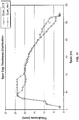
- first sparcap 40 and/or second sparcap 44 has a thickness distribution as shown in Figure 11 .
- rotor blade 18 has a span along the length of rotor blade 18 between root section 20 and tip end 22 of about 55 meters (m) and first sparcap 40 and/or second sparcap 44 has a width between leading edge 30 and trailing edge 32 of about 650 millimeters (mm).
- a thickness of first sparcap 40 and/or second sparcap 44 varies along the span of rotor blade 18 and the thickness of first sparcap 40 and/or the thickness of second sparcap 44 at any cross-section of rotor blade 18 depends on design requirements. However, in the embodiment shown in Figure 11 , the thickness of first sparcap 40 and/or the thickness of second sparcap 44 of rotor blade 18 (having a length of about 55 m) varies from about 1 mm to about 50 mm. Further, a thickness of first carbon material layer 50 and a thickness of second carbon material layer 56 may vary to provide any suitable portion of the respective sparcap thickness. Similarly, a thickness of core material layer 52 may vary to provide any suitable portion of the respective sparcap thickness. For example, in one embodiment, the thickness of core material layer 52 varies from about 6 mm to about 36 mm.
- first carbon material layer 50, core material section 52, and/or second carbon material layer 56 may have any suitable thickness such that the thickness distribution of sparcap 40 and/or sparcap 44 along a length of rotor blade 18 between root section 20 and tip end 22 is optimized to prevent or limit buckling at buckling prone region(s) 54 of rotor blade 18. Further, it should be apparent to those skilled in the art and guided by the teachings herein provided that first carbon material layer 50 and second carbon material layer 56 may include any suitable number of layers of carbon material, and that any suitable number of core material sections having suitable dimensions may be positioned with respect to buckling prone region(s) 54 of rotor blade 18.
- first carbon material layer 50 and second carbon material layer 56 may be integrated or formed as a unitary carbon material layer with one or more core material sections 52 distributed throughout the unitary carbon material layer and positioned with respect to buckling prone region(s) 54 of rotor blade 18.
- a method for fabricating rotor blade 18 for a wind turbine includes providing a first blade section and a cooperating second blade section. Each of the first blade section and the second blade section has a leading edge and a trailing edge.
- a first sparcap is coupled to, such as applied to or formed or laminated on, an inner surface of the first blade section.
- the first sparcap includes at least one carbon material layer and at least one core material section.
- a second sparcap is coupled to, such as applied to or formed or laminated on, an inner surface of the second blade section.
- the second sparcap includes at least one carbon material layer and at least one core material section.
- the second sparcap is coupled to the first sparcap with a suitable sparweb.
- a first carbon material layer is coupled to, such as formed on or applied or laminated to, the inner surface of the first blade section.
- the first carbon material layer extends along at least a portion of a length of the wind turbine rotor blade.
- One or more core material sections are positioned on the first carbon material layer and a second carbon material layer is coupled to, such as formed on or applied or laminated to, the one or more core material sections.
- the second carbon material layer extends along at least a portion of the length of the wind turbine rotor blade.
- the second sparcap is coupled to an inner surface of the second blade section.
- Table 1 Modes Buckling bins (8 Nos) 0 45 90 135 180 225 270 315 1 0.55 0.92 3.77 0.64 0.54 2.05 1.31 0.66 2 0.55 0.93 3.79 0.64 0.54 2.07 1.33 0.67 3 0.56 0.93 3.82 0.67 0.56 2.06 1.48 0.75
- Table 2 Modes Buckling bins (8 Nos) 0 45 90 135 180 225 270 315 1 1.06 1.43 5.90 1.25 1.25 3.49 2.74 1.67 2 1.08 1.47 5.96 1.25 1.27 3.54 2.76 1.68 3 1.25 1.78 5.97 1.27 1.52 3.69 3.05 1.80
- a 55 m rotor blade was analyzed to determine a rotor blade buckling strength.
- the rotor blade was initially provided with a sparcap having a width of 650 mm and buckling analysis was performed.
- Table 1 shows buckling load factors for eight different load bins and for the first three modes for a conventional rotor blade including a carbon sparcap.
- a buckling load factor indicates a percentage of the applied load required for the rotor blade to buckle.
- Table 2 shows buckling load factors for eight different load bins and for the first three modes for a rotor blade including a sparcap made of a carbon material and a core material, as described herein. Referring to Table 2, utilizing or positioning a core material at or near a buckling prone region of the rotor blade increases a minimum buckling load factor to about 106 % from about 55 % for the conventional rotor blade.
- buckling of a rotor blade can be avoided with the use of a core material section having a thickness of 25 mm with a suitable carbon material positioned at or near a buckling prone region of the rotor blade.
- a rotor blade having a sparcap fabricated only of carbon material has a total weight of 6,758 kilograms (kg) and a sparcap weight of 1,729 kg, while a rotor blade having a sparcap fabricated of a carbon material and a core material has a total weight of 6,685 kg and a sparcap weight of 1,656 kg (1,631 kg or carbon and 25 kg of core material).
- the sparcap as described herein including a carbon material and a core material is 73 kg lighter than a conventional sparcap including only a carbon material.
- Conventional sparcaps made only of a carbon material require an additional 98 kg of carbon to suppress buckling, while the sparcap as described herein requires a core material of about 25 kg to sufficiently address identical buckling considerations.
- Usage of the sparcap described herein saves about 98 kg of carbon material with a consumption of about 25 kg of core material, while satisfying strength, bending stiffness and buckling stiffness requirements.
- the sparcap as described herein effectively combines the beneficial properties of a carbon material and a less-costly core material to facilitate significantly improving a buckling factor of the rotor blade.
- the sparcap as described herein facilitates fabricating a longer and lighter rotor blade, significantly increases a sparcap buckling failure margin by efficient use of materials, and enables wind turbine rotor blade designers to choose and optimize a sparcap width, length, and/or thickness (including a thickness distribution along the length and/or the width of the rotor blade) for a cost-effective, lighter sparcap.
Claims (9)
- Longeron (40, 44) pour une pale de rotor d'éolienne (18), ledit longeron comprenant :une première couche de matériau de carbone (50) couplée à une surface interne (46) de la pale de rotor d'éolienne, ladite première couche de matériau de carbone s'étendant sur au moins une portion d'une longueur de la pale de rotor d'éolienne ;une pluralité de sections de matériau central non contiguës et séparées (52) couplées à ladite première couche de matériau de carbone, lesdites sections de matériau central étant positionnées sur la longueur de la pale de rotor d'éolienne (18) par rapport à des régions sujettes au flambement (54) de la pale de rotor d'éolienne ; etune seconde couche de matériau de carbone (56) recouvrant ledit matériau central est couplée à au moins l'un de ladite première couche de matériau de carbone et dudit matériau central, ladite seconde couche de matériau de carbone s'étendant sur au moins une portion de la longueur de la pale de rotor d'éolienne.
- Longeron (40, 44) selon la revendication 1, dans lequel ledit matériau central s'étend sur au moins une portion de la longueur de la pale de rotor d'éolienne.
- Longeron (40, 44) selon la revendication 1, dans lequel chaque section de matériau central (52) de ladite pluralité de sections de matériau central est positionnée par rapport à une région sujette au flambement correspondante (54) de la pale de rotor d'éolienne (18).
- Longeron (40, 44) selon une quelconque revendication précédente, dans lequel une épaisseur dudit longeron varie sur une longueur de ladite pale de rotor (18).
- Longeron (40, 44) selon une quelconque revendication précédente, dans lequel ledit longeron a une distribution d'épaisseur qui varie sur une longueur de la pale de rotor d'éolienne (18).
- Longeron (40, 44) selon une quelconque revendication précédente, dans lequel chacune de ladite première couche de matériau de carbone (50) et de ladite seconde couche de matériau de carbone (56) comprend une pluralité de fibres de carbone.
- Longeron (40, 44) selon une quelconque revendication précédente, dans lequel chacune de ladite première couche de matériau de carbone (50) et de ladite seconde couche de matériau de carbone (56) comprend une matrice renforcée par des fibres de carbone.
- Longeron (40, 44) selon une quelconque revendication précédente, dans lequel ledit matériau central comprend au moins l'un d'un matériau en mousse, d'un matériau ligneux et d'un matériau polymère.
- Pale de rotor (18) pour une éolienne (10), ladite pale de rotor comprenant :une première section de pale (26) et une seconde section de pale (28) couplée à ladite première section de pale pour former ladite pale de rotor (18), ladite première section de pale et ladite seconde section de pale étant couplées au niveau d'un bord d'attaque (30) et d'un bord de fuite (32) de la pale de rotor (18) ;un premier longeron (46) couplé à ladite première section de pale ; etun second longeron (44) couplé à ladite seconde section de pale, chacun dudit premier longeron et dudit second longeron comprenant :une première couche de matériau de carbone (50) couplée à une surface interne (46) d'une section de pale respective, ladite première couche de matériau de carbone s'étendant sur au moins une portion d'une longueur de ladite pale de rotor ;une pluralité de sections de matériau central non contiguës et séparées (52) couplées à ladite première couche de matériau de carbone, lesdites sections de matériau central étant positionnées sur la longueur de la pale de rotor (18) par rapport à des régions sujettes au flambement (54) de la pale de rotor ; etune seconde couche de matériau de carbone recouvrant ledit matériau central et couplée à au moins l'un de ladite première couche de matériau de carbone et dudit matériau central, ladite seconde couche de matériau de carbone (56) s'étendant sur au moins une portion de la longueur de la pale de rotor.
Applications Claiming Priority (1)
| Application Number | Priority Date | Filing Date | Title |
|---|---|---|---|
| US12/332,840 US7942637B2 (en) | 2008-12-11 | 2008-12-11 | Sparcap for wind turbine rotor blade and method of fabricating wind turbine rotor blade |
Publications (3)
| Publication Number | Publication Date |
|---|---|
| EP2204576A2 EP2204576A2 (fr) | 2010-07-07 |
| EP2204576A3 EP2204576A3 (fr) | 2015-07-01 |
| EP2204576B1 true EP2204576B1 (fr) | 2018-08-15 |
Family
ID=42184112
Family Applications (1)
| Application Number | Title | Priority Date | Filing Date |
|---|---|---|---|
| EP09177438.0A Not-in-force EP2204576B1 (fr) | 2008-12-11 | 2009-11-30 | Longeron pour une pale de rotor d'éolienne et procédé de fabrication de pale de rotor d'éolienne |
Country Status (3)
| Country | Link |
|---|---|
| US (1) | US7942637B2 (fr) |
| EP (1) | EP2204576B1 (fr) |
| CN (1) | CN101749174B (fr) |
Families Citing this family (22)
| Publication number | Priority date | Publication date | Assignee | Title |
|---|---|---|---|---|
| JP5656861B2 (ja) | 2008-12-05 | 2015-01-21 | モジュラー ウィンド エナジー インコーポレイテッド | 効率が良い風力タービンブレード、風力タービンブレードの構造、ならびに、関連したシステム、および、製造、組み立て、および、使用の方法 |
| US8079819B2 (en) * | 2009-05-21 | 2011-12-20 | Zuteck Michael D | Optimization of premium fiber material usage in wind turbine spars |
| JP2011137386A (ja) * | 2009-12-25 | 2011-07-14 | Mitsubishi Heavy Ind Ltd | 風車回転翼および風車回転翼の製造方法 |
| DE102010002432A1 (de) * | 2010-02-26 | 2011-09-01 | Repower Systems Ag | Rotorblatt für eine Windenergieanlage, Windenergieanlage und Verfahren zum Herstellen eines Rotorblatts |
| US8192169B2 (en) | 2010-04-09 | 2012-06-05 | Frederick W Piasecki | Highly reliable, low cost wind turbine rotor blade |
| EP2402594A1 (fr) * | 2010-07-01 | 2012-01-04 | Lm Glasfiber A/S | Pale d'éolienne pour un rotor d'une éolienne |
| CN102108946B (zh) * | 2011-01-17 | 2013-01-09 | 南京航空航天大学 | 复合铺层式风力机叶片及其制造方法 |
| US20120027609A1 (en) * | 2011-05-17 | 2012-02-02 | Prasad Ogde | Wind turbine rotor blade with precured fiber rods and method for producing the same |
| GB201109412D0 (en) * | 2011-06-03 | 2011-07-20 | Blade Dynamics Ltd | A wind turbine rotor |
| FR2980514B1 (fr) | 2011-09-23 | 2018-01-05 | Flakt Solyvent-Ventec | Pale de machine tournante a structure modulaire renforcee |
| US9470205B2 (en) * | 2013-03-13 | 2016-10-18 | Vestas Wind Systems A/S | Wind turbine blades with layered, multi-component spars, and associated systems and methods |
| US9541061B2 (en) | 2014-03-04 | 2017-01-10 | Siemens Energy, Inc. | Wind turbine blade with viscoelastic damping |
| CN104441693A (zh) * | 2014-12-05 | 2015-03-25 | 苗宏伟 | 一种风力发电叶片新型复合材料胶膜成型工艺方法 |
| US9845786B2 (en) * | 2014-12-12 | 2017-12-19 | General Electric Company | Spar cap for a wind turbine rotor blade |
| US10072632B2 (en) * | 2015-06-30 | 2018-09-11 | General Electric Company | Spar cap for a wind turbine rotor blade formed from pre-cured laminate plates of varying thicknesses |
| US9951750B2 (en) * | 2015-07-30 | 2018-04-24 | General Electric Company | Rotor blade with interior shelf for a flat plate spar cap |
| DK3394430T3 (da) * | 2015-12-23 | 2021-12-06 | Lm Wp Patent Holding As | Vindmøllevinger og tilknyttede fremgangsmåder til fremstilling |
| US10677216B2 (en) | 2017-10-24 | 2020-06-09 | General Electric Company | Wind turbine rotor blade components formed using pultruded rods |
| US11738530B2 (en) | 2018-03-22 | 2023-08-29 | General Electric Company | Methods for manufacturing wind turbine rotor blade components |
| US11002309B2 (en) * | 2018-07-31 | 2021-05-11 | Lockheed Martin Corporation | Hybrid rotor shaft for a vertical take-off and landing (VTOL) aircraft |
| ES2926076T3 (es) * | 2019-04-03 | 2022-10-21 | Siemens Gamesa Renewable Energy As | Pala de turbina eólica y turbina eólica |
| CN117581013A (zh) * | 2021-06-30 | 2024-02-20 | 维斯塔斯风力系统有限公司 | 用于风轮机的叶片 |
Family Cites Families (40)
| Publication number | Priority date | Publication date | Assignee | Title |
|---|---|---|---|---|
| US4081220A (en) * | 1976-12-17 | 1978-03-28 | United Technologies Corporation | Semi-spar wound blade |
| US4264278A (en) * | 1977-10-31 | 1981-04-28 | Oscar Weingart | Blade or spar |
| JPS5476333A (en) | 1977-11-30 | 1979-06-18 | Nippon Gakki Seizo Kk | Frp racket using glass fiber and carbon fiber in combina tion |
| JPH07107104B2 (ja) | 1987-11-30 | 1995-11-15 | イビデン株式会社 | 炭素繊維強化複合材料用の柔軟性中間材及びその製造方法 |
| US4976587A (en) * | 1988-07-20 | 1990-12-11 | Dwr Wind Technologies Inc. | Composite wind turbine rotor blade and method for making same |
| JPH03788A (ja) | 1989-05-29 | 1991-01-07 | Nippon Pillar Packing Co Ltd | 炭素繊維複合膨張黒鉛パッキンおよびその製造方法 |
| JPH03187726A (ja) | 1989-12-18 | 1991-08-15 | Mitsubishi Kasei Corp | 繊維強化樹脂成形体およびその製造方法 |
| JPH03247368A (ja) | 1990-02-27 | 1991-11-05 | Kazama Sports Hanbai Kk | 軽量スキーの芯構造 |
| AT398064B (de) * | 1992-07-01 | 1994-09-26 | Hoac Austria Flugzeugwerk Wr N | Kunststoff-verbundprofil, insbesondere flügelholm für den flugzeugbau |
| US5375324A (en) * | 1993-07-12 | 1994-12-27 | Flowind Corporation | Vertical axis wind turbine with pultruded blades |
| JP3089984B2 (ja) | 1994-03-07 | 2000-09-18 | 東レ株式会社 | 補強織物とその製造方法および製造装置 |
| WO1996006776A1 (fr) * | 1994-08-31 | 1996-03-07 | United Technologies Corporation | Longeron composite renforce par fibres pour aeronef a voilure tournante et son procede de fabrication |
| JPH1016072A (ja) | 1996-06-26 | 1998-01-20 | Japan Steel Works Ltd:The | 複合材料の製造方法 |
| JP3070916B2 (ja) | 1997-10-16 | 2000-07-31 | 嘉司 松本 | 補強材及び補強材の製造方法 |
| JPH11262546A (ja) | 1998-03-17 | 1999-09-28 | Mizuno Corp | ラケットフレーム |
| ES2297873T3 (es) * | 1998-12-16 | 2008-05-01 | Lantor B.V. | Material de nucleo para sistemas de molde cerrado. |
| JP2001246686A (ja) | 2000-03-07 | 2001-09-11 | Toyota Autom Loom Works Ltd | 複合材料構造体 |
| DK1417409T4 (en) * | 2001-07-19 | 2017-07-31 | Vestas Wind Sys As | Wind turbine blades |
| JP3891092B2 (ja) * | 2001-10-23 | 2007-03-07 | ヤマハ株式会社 | ステアリングホイール |
| DK175275B1 (da) * | 2002-03-19 | 2004-08-02 | Lm Glasfiber As | Overgangsområde i vindmöllevinge |
| ES2282616T3 (es) | 2003-03-06 | 2007-10-16 | Vestas Wind Systems A/S | Conexion entre materiales compuestos con propiedades con compatibles y procedimiento de preparacion. |
| DE10336461A1 (de) * | 2003-08-05 | 2005-03-03 | Aloys Wobben | Verfahren zur Herstellung eines Rotorblattes einer Windenergieanlage |
| JP4214034B2 (ja) | 2003-10-30 | 2009-01-28 | 庄治郎 落合 | 金属基炭素繊維強化複合材料およびその製造方法 |
| US20050186081A1 (en) * | 2004-02-24 | 2005-08-25 | Mohamed Mansour H. | Wind blade spar cap and method of making |
| JP2006044037A (ja) | 2004-08-04 | 2006-02-16 | Honda Motor Co Ltd | 樹脂成形体及び該成形体を含む複合樹脂製品並びにこれらの製造方法 |
| JP4561344B2 (ja) | 2004-12-07 | 2010-10-13 | 東レ株式会社 | 翼部材 |
| ES2255454B1 (es) * | 2004-12-15 | 2007-07-01 | Gamesa Eolica, S.A. | Sistema pararrayos para pala de aerogenerador. |
| US7153090B2 (en) * | 2004-12-17 | 2006-12-26 | General Electric Company | System and method for passive load attenuation in a wind turbine |
| JP2006226327A (ja) | 2005-02-15 | 2006-08-31 | Kyoto Institute Of Technology | Frp製コイルばね及びその生産方法 |
| US20060225278A1 (en) * | 2005-03-31 | 2006-10-12 | Lin Wendy W | Wind blade construction and system and method thereof |
| JP4696651B2 (ja) | 2005-04-04 | 2011-06-08 | トヨタ自動車株式会社 | 車両のピラー構造体 |
| US20070149084A1 (en) * | 2005-12-22 | 2007-06-28 | Magna International Inc. | Natural fiber as core material in composite sandwich structure |
| JP2007170328A (ja) | 2005-12-26 | 2007-07-05 | Toray Ind Inc | 風力発電用風車翼およびその製造方法 |
| US7427189B2 (en) * | 2006-02-13 | 2008-09-23 | General Electric Company | Wind turbine rotor blade |
| US7758313B2 (en) * | 2006-02-13 | 2010-07-20 | General Electric Company | Carbon-glass-hybrid spar for wind turbine rotorblades |
| US20070251090A1 (en) * | 2006-04-28 | 2007-11-01 | General Electric Company | Methods and apparatus for fabricating blades |
| US7976282B2 (en) * | 2007-01-26 | 2011-07-12 | General Electric Company | Preform spar cap for a wind turbine rotor blade |
| EP2109713B1 (fr) * | 2007-01-29 | 2013-07-24 | Bladena ApS | Aube d'éolienne |
| ES2342638B1 (es) * | 2007-02-28 | 2011-05-13 | GAMESA INNOVATION & TECHNOLOGY, S.L. | Una pala de aerogenerador multi-panel. |
| DK1990178T3 (da) * | 2007-05-07 | 2010-10-04 | Siemens Ag | Fremgangsmåde til at fremstille et rotorblad til en vindmølle |
-
2008
- 2008-12-11 US US12/332,840 patent/US7942637B2/en active Active
-
2009
- 2009-11-30 EP EP09177438.0A patent/EP2204576B1/fr not_active Not-in-force
- 2009-12-11 CN CN200910258700XA patent/CN101749174B/zh active Active
Non-Patent Citations (2)
| Title |
|---|
| ELSEVIER LTD ET AL: "What are the tools of the wind turbine blade trade? - Renewable Energy Focus", 1 October 2008 (2008-10-01), XP055388749, Retrieved from the Internet <URL:http://www.renewableenergyfocus.com/view/3292/what-are-the-tools-of-the-wind-turbine-blade-trade/> [retrieved on 20170706] * |
| GRIFFIN D A ET AL: "Alternative Composite Materials for Megawatt-Scale Wind Turbine Blades: Design Considerations and Recommended Testing", ASME WIND ENERGY SYMPOSIUM, XX, XX, 1 January 2003 (2003-01-01), pages 1 - 11, XP002321843 * |
Also Published As
| Publication number | Publication date |
|---|---|
| US20100143147A1 (en) | 2010-06-10 |
| US7942637B2 (en) | 2011-05-17 |
| EP2204576A2 (fr) | 2010-07-07 |
| EP2204576A3 (fr) | 2015-07-01 |
| CN101749174A (zh) | 2010-06-23 |
| CN101749174B (zh) | 2013-04-17 |
Similar Documents
| Publication | Publication Date | Title |
|---|---|---|
| EP2204576B1 (fr) | Longeron pour une pale de rotor d'éolienne et procédé de fabrication de pale de rotor d'éolienne | |
| EP2239461A2 (fr) | Système de longeron pour une pale de rotor d'éolienne et procédé de fabrication de pale de rotor d'éolienne | |
| EP2511477B1 (fr) | Pale d'éolienne dotée d'une région de transition | |
| US11454208B2 (en) | Pultruded fibrous composite strips having non-planar profiles cross-section for wind turbine blade spar caps | |
| DK2363599T3 (en) | A rotor blade for a wind turbine, wind turbine and method of producing a rotor blade | |
| US10066491B2 (en) | Fibre composite component for the rotor blade of a wind turbine | |
| US7427189B2 (en) | Wind turbine rotor blade | |
| US8753092B2 (en) | Rotor blade for a wind turbine and methods of manufacturing the same | |
| US8480371B2 (en) | Wind turbine rotor blade and wind-generating wind turbine | |
| US20110182742A1 (en) | Wind turbine blade and wind turbine generator using the same | |
| US20110286853A1 (en) | Blade of a wind turbine | |
| WO2013010979A2 (fr) | Pale de turbine éolienne présentant une région de transition | |
| CN106321345B (zh) | 由预处理层压板形成的风轮机转子叶片的翼梁缘条 | |
| EP2915996A1 (fr) | Pale d'éolienne avec amortissement viscoélastique | |
| CN115485127A (zh) | 风力涡轮机叶片 | |
| US20240018938A1 (en) | Wind turbine blade having buckling-resistant spar caps | |
| US20230358208A1 (en) | Wind turbine blade with reinforcing structure | |
| EP4363710A1 (fr) | Pale d'éolienne | |
| CN117616196A (zh) | 风力涡轮机叶片 | |
| WO2023117013A1 (fr) | Améliorations apportées à des pales d'éolienne | |
| CN114630957A (zh) | 风力涡轮机叶片 |
Legal Events
| Date | Code | Title | Description |
|---|---|---|---|
| PUAI | Public reference made under article 153(3) epc to a published international application that has entered the european phase |
Free format text: ORIGINAL CODE: 0009012 |
|
| AK | Designated contracting states |
Kind code of ref document: A2 Designated state(s): AT BE BG CH CY CZ DE DK EE ES FI FR GB GR HR HU IE IS IT LI LT LU LV MC MK MT NL NO PL PT RO SE SI SK SM TR |
|
| AX | Request for extension of the european patent |
Extension state: AL BA RS |
|
| PUAL | Search report despatched |
Free format text: ORIGINAL CODE: 0009013 |
|
| AK | Designated contracting states |
Kind code of ref document: A3 Designated state(s): AT BE BG CH CY CZ DE DK EE ES FI FR GB GR HR HU IE IS IT LI LT LU LV MC MK MT NL NO PL PT RO SE SI SK SM TR |
|
| AX | Request for extension of the european patent |
Extension state: AL BA RS |
|
| RIC1 | Information provided on ipc code assigned before grant |
Ipc: F03D 11/00 20060101ALI20150526BHEP Ipc: F03D 1/06 20060101AFI20150526BHEP |
|
| 17P | Request for examination filed |
Effective date: 20160104 |
|
| RBV | Designated contracting states (corrected) |
Designated state(s): AT BE BG CH CY CZ DE DK EE ES FI FR GB GR HR HU IE IS IT LI LT LU LV MC MK MT NL NO PL PT RO SE SI SK SM TR |
|
| 17Q | First examination report despatched |
Effective date: 20160620 |
|
| REG | Reference to a national code |
Ref country code: DE Ref legal event code: R079 Ref document number: 602009053837 Country of ref document: DE Free format text: PREVIOUS MAIN CLASS: F03D0001060000 Ipc: F03D0080000000 |
|
| RIC1 | Information provided on ipc code assigned before grant |
Ipc: F03D 1/06 20060101ALI20180215BHEP Ipc: F03D 80/00 20160101AFI20180215BHEP |
|
| GRAP | Despatch of communication of intention to grant a patent |
Free format text: ORIGINAL CODE: EPIDOSNIGR1 |
|
| INTG | Intention to grant announced |
Effective date: 20180413 |
|
| GRAS | Grant fee paid |
Free format text: ORIGINAL CODE: EPIDOSNIGR3 |
|
| GRAA | (expected) grant |
Free format text: ORIGINAL CODE: 0009210 |
|
| AK | Designated contracting states |
Kind code of ref document: B1 Designated state(s): AT BE BG CH CY CZ DE DK EE ES FI FR GB GR HR HU IE IS IT LI LT LU LV MC MK MT NL NO PL PT RO SE SI SK SM TR |
|
| REG | Reference to a national code |
Ref country code: CH Ref legal event code: EP Ref country code: GB Ref legal event code: FG4D Ref country code: AT Ref legal event code: REF Ref document number: 1030082 Country of ref document: AT Kind code of ref document: T Effective date: 20180815 |
|
| REG | Reference to a national code |
Ref country code: IE Ref legal event code: FG4D |
|
| REG | Reference to a national code |
Ref country code: DE Ref legal event code: R096 Ref document number: 602009053837 Country of ref document: DE |
|
| REG | Reference to a national code |
Ref country code: NL Ref legal event code: MP Effective date: 20180815 |
|
| REG | Reference to a national code |
Ref country code: LT Ref legal event code: MG4D |
|
| REG | Reference to a national code |
Ref country code: AT Ref legal event code: MK05 Ref document number: 1030082 Country of ref document: AT Kind code of ref document: T Effective date: 20180815 |
|
| PG25 | Lapsed in a contracting state [announced via postgrant information from national office to epo] |
Ref country code: IS Free format text: LAPSE BECAUSE OF FAILURE TO SUBMIT A TRANSLATION OF THE DESCRIPTION OR TO PAY THE FEE WITHIN THE PRESCRIBED TIME-LIMIT Effective date: 20181215 Ref country code: NL Free format text: LAPSE BECAUSE OF FAILURE TO SUBMIT A TRANSLATION OF THE DESCRIPTION OR TO PAY THE FEE WITHIN THE PRESCRIBED TIME-LIMIT Effective date: 20180815 Ref country code: FI Free format text: LAPSE BECAUSE OF FAILURE TO SUBMIT A TRANSLATION OF THE DESCRIPTION OR TO PAY THE FEE WITHIN THE PRESCRIBED TIME-LIMIT Effective date: 20180815 Ref country code: LT Free format text: LAPSE BECAUSE OF FAILURE TO SUBMIT A TRANSLATION OF THE DESCRIPTION OR TO PAY THE FEE WITHIN THE PRESCRIBED TIME-LIMIT Effective date: 20180815 Ref country code: SE Free format text: LAPSE BECAUSE OF FAILURE TO SUBMIT A TRANSLATION OF THE DESCRIPTION OR TO PAY THE FEE WITHIN THE PRESCRIBED TIME-LIMIT Effective date: 20180815 Ref country code: NO Free format text: LAPSE BECAUSE OF FAILURE TO SUBMIT A TRANSLATION OF THE DESCRIPTION OR TO PAY THE FEE WITHIN THE PRESCRIBED TIME-LIMIT Effective date: 20181115 Ref country code: GR Free format text: LAPSE BECAUSE OF FAILURE TO SUBMIT A TRANSLATION OF THE DESCRIPTION OR TO PAY THE FEE WITHIN THE PRESCRIBED TIME-LIMIT Effective date: 20181116 Ref country code: BG Free format text: LAPSE BECAUSE OF FAILURE TO SUBMIT A TRANSLATION OF THE DESCRIPTION OR TO PAY THE FEE WITHIN THE PRESCRIBED TIME-LIMIT Effective date: 20181115 Ref country code: AT Free format text: LAPSE BECAUSE OF FAILURE TO SUBMIT A TRANSLATION OF THE DESCRIPTION OR TO PAY THE FEE WITHIN THE PRESCRIBED TIME-LIMIT Effective date: 20180815 |
|
| PG25 | Lapsed in a contracting state [announced via postgrant information from national office to epo] |
Ref country code: HR Free format text: LAPSE BECAUSE OF FAILURE TO SUBMIT A TRANSLATION OF THE DESCRIPTION OR TO PAY THE FEE WITHIN THE PRESCRIBED TIME-LIMIT Effective date: 20180815 Ref country code: LV Free format text: LAPSE BECAUSE OF FAILURE TO SUBMIT A TRANSLATION OF THE DESCRIPTION OR TO PAY THE FEE WITHIN THE PRESCRIBED TIME-LIMIT Effective date: 20180815 Ref country code: ES Free format text: LAPSE BECAUSE OF FAILURE TO SUBMIT A TRANSLATION OF THE DESCRIPTION OR TO PAY THE FEE WITHIN THE PRESCRIBED TIME-LIMIT Effective date: 20180815 |
|
| PG25 | Lapsed in a contracting state [announced via postgrant information from national office to epo] |
Ref country code: IT Free format text: LAPSE BECAUSE OF FAILURE TO SUBMIT A TRANSLATION OF THE DESCRIPTION OR TO PAY THE FEE WITHIN THE PRESCRIBED TIME-LIMIT Effective date: 20180815 Ref country code: CZ Free format text: LAPSE BECAUSE OF FAILURE TO SUBMIT A TRANSLATION OF THE DESCRIPTION OR TO PAY THE FEE WITHIN THE PRESCRIBED TIME-LIMIT Effective date: 20180815 Ref country code: EE Free format text: LAPSE BECAUSE OF FAILURE TO SUBMIT A TRANSLATION OF THE DESCRIPTION OR TO PAY THE FEE WITHIN THE PRESCRIBED TIME-LIMIT Effective date: 20180815 Ref country code: RO Free format text: LAPSE BECAUSE OF FAILURE TO SUBMIT A TRANSLATION OF THE DESCRIPTION OR TO PAY THE FEE WITHIN THE PRESCRIBED TIME-LIMIT Effective date: 20180815 Ref country code: PL Free format text: LAPSE BECAUSE OF FAILURE TO SUBMIT A TRANSLATION OF THE DESCRIPTION OR TO PAY THE FEE WITHIN THE PRESCRIBED TIME-LIMIT Effective date: 20180815 |
|
| REG | Reference to a national code |
Ref country code: DE Ref legal event code: R097 Ref document number: 602009053837 Country of ref document: DE |
|
| PG25 | Lapsed in a contracting state [announced via postgrant information from national office to epo] |
Ref country code: SK Free format text: LAPSE BECAUSE OF FAILURE TO SUBMIT A TRANSLATION OF THE DESCRIPTION OR TO PAY THE FEE WITHIN THE PRESCRIBED TIME-LIMIT Effective date: 20180815 Ref country code: SM Free format text: LAPSE BECAUSE OF FAILURE TO SUBMIT A TRANSLATION OF THE DESCRIPTION OR TO PAY THE FEE WITHIN THE PRESCRIBED TIME-LIMIT Effective date: 20180815 Ref country code: DK Free format text: LAPSE BECAUSE OF FAILURE TO SUBMIT A TRANSLATION OF THE DESCRIPTION OR TO PAY THE FEE WITHIN THE PRESCRIBED TIME-LIMIT Effective date: 20180815 |
|
| REG | Reference to a national code |
Ref country code: DE Ref legal event code: R119 Ref document number: 602009053837 Country of ref document: DE |
|
| PLBE | No opposition filed within time limit |
Free format text: ORIGINAL CODE: 0009261 |
|
| STAA | Information on the status of an ep patent application or granted ep patent |
Free format text: STATUS: NO OPPOSITION FILED WITHIN TIME LIMIT |
|
| REG | Reference to a national code |
Ref country code: CH Ref legal event code: PL |
|
| 26N | No opposition filed |
Effective date: 20190516 |
|
| GBPC | Gb: european patent ceased through non-payment of renewal fee |
Effective date: 20181130 |
|
| PG25 | Lapsed in a contracting state [announced via postgrant information from national office to epo] |
Ref country code: LU Free format text: LAPSE BECAUSE OF NON-PAYMENT OF DUE FEES Effective date: 20181130 Ref country code: MC Free format text: LAPSE BECAUSE OF FAILURE TO SUBMIT A TRANSLATION OF THE DESCRIPTION OR TO PAY THE FEE WITHIN THE PRESCRIBED TIME-LIMIT Effective date: 20180815 |
|
| REG | Reference to a national code |
Ref country code: BE Ref legal event code: MM Effective date: 20181130 |
|
| REG | Reference to a national code |
Ref country code: IE Ref legal event code: MM4A |
|
| PG25 | Lapsed in a contracting state [announced via postgrant information from national office to epo] |
Ref country code: CH Free format text: LAPSE BECAUSE OF NON-PAYMENT OF DUE FEES Effective date: 20181130 Ref country code: LI Free format text: LAPSE BECAUSE OF NON-PAYMENT OF DUE FEES Effective date: 20181130 Ref country code: SI Free format text: LAPSE BECAUSE OF FAILURE TO SUBMIT A TRANSLATION OF THE DESCRIPTION OR TO PAY THE FEE WITHIN THE PRESCRIBED TIME-LIMIT Effective date: 20180815 |
|
| PG25 | Lapsed in a contracting state [announced via postgrant information from national office to epo] |
Ref country code: IE Free format text: LAPSE BECAUSE OF NON-PAYMENT OF DUE FEES Effective date: 20181130 Ref country code: DE Free format text: LAPSE BECAUSE OF NON-PAYMENT OF DUE FEES Effective date: 20190601 Ref country code: FR Free format text: LAPSE BECAUSE OF NON-PAYMENT OF DUE FEES Effective date: 20181130 |
|
| PG25 | Lapsed in a contracting state [announced via postgrant information from national office to epo] |
Ref country code: BE Free format text: LAPSE BECAUSE OF NON-PAYMENT OF DUE FEES Effective date: 20181130 |
|
| PG25 | Lapsed in a contracting state [announced via postgrant information from national office to epo] |
Ref country code: GB Free format text: LAPSE BECAUSE OF NON-PAYMENT OF DUE FEES Effective date: 20181130 |
|
| PG25 | Lapsed in a contracting state [announced via postgrant information from national office to epo] |
Ref country code: MT Free format text: LAPSE BECAUSE OF NON-PAYMENT OF DUE FEES Effective date: 20181130 |
|
| PG25 | Lapsed in a contracting state [announced via postgrant information from national office to epo] |
Ref country code: TR Free format text: LAPSE BECAUSE OF FAILURE TO SUBMIT A TRANSLATION OF THE DESCRIPTION OR TO PAY THE FEE WITHIN THE PRESCRIBED TIME-LIMIT Effective date: 20180815 |
|
| PG25 | Lapsed in a contracting state [announced via postgrant information from national office to epo] |
Ref country code: PT Free format text: LAPSE BECAUSE OF FAILURE TO SUBMIT A TRANSLATION OF THE DESCRIPTION OR TO PAY THE FEE WITHIN THE PRESCRIBED TIME-LIMIT Effective date: 20180815 |
|
| PG25 | Lapsed in a contracting state [announced via postgrant information from national office to epo] |
Ref country code: HU Free format text: LAPSE BECAUSE OF FAILURE TO SUBMIT A TRANSLATION OF THE DESCRIPTION OR TO PAY THE FEE WITHIN THE PRESCRIBED TIME-LIMIT; INVALID AB INITIO Effective date: 20091130 Ref country code: MK Free format text: LAPSE BECAUSE OF NON-PAYMENT OF DUE FEES Effective date: 20180815 Ref country code: CY Free format text: LAPSE BECAUSE OF FAILURE TO SUBMIT A TRANSLATION OF THE DESCRIPTION OR TO PAY THE FEE WITHIN THE PRESCRIBED TIME-LIMIT Effective date: 20180815 |
|
| P01 | Opt-out of the competence of the unified patent court (upc) registered |
Effective date: 20230522 |