EP2204280A2 - Procédé et appareil d'alimentation de sacs dans une machine d'emballage - Google Patents
Procédé et appareil d'alimentation de sacs dans une machine d'emballage Download PDFInfo
- Publication number
- EP2204280A2 EP2204280A2 EP09015916A EP09015916A EP2204280A2 EP 2204280 A2 EP2204280 A2 EP 2204280A2 EP 09015916 A EP09015916 A EP 09015916A EP 09015916 A EP09015916 A EP 09015916A EP 2204280 A2 EP2204280 A2 EP 2204280A2
- Authority
- EP
- European Patent Office
- Prior art keywords
- bags
- bag
- conveyor
- transportation means
- supply
- Prior art date
- Legal status (The legal status is an assumption and is not a legal conclusion. Google has not performed a legal analysis and makes no representation as to the accuracy of the status listed.)
- Granted
Links
Images


Classifications
-
- B—PERFORMING OPERATIONS; TRANSPORTING
- B65—CONVEYING; PACKING; STORING; HANDLING THIN OR FILAMENTARY MATERIAL
- B65B—MACHINES, APPARATUS OR DEVICES FOR, OR METHODS OF, PACKAGING ARTICLES OR MATERIALS; UNPACKING
- B65B43/00—Forming, feeding, opening or setting-up containers or receptacles in association with packaging
- B65B43/12—Feeding flexible bags or carton blanks in flat or collapsed state; Feeding flat bags connected to form a series or chain
-
- B—PERFORMING OPERATIONS; TRANSPORTING
- B65—CONVEYING; PACKING; STORING; HANDLING THIN OR FILAMENTARY MATERIAL
- B65B—MACHINES, APPARATUS OR DEVICES FOR, OR METHODS OF, PACKAGING ARTICLES OR MATERIALS; UNPACKING
- B65B43/00—Forming, feeding, opening or setting-up containers or receptacles in association with packaging
- B65B43/04—Forming flat bags from webs
-
- B—PERFORMING OPERATIONS; TRANSPORTING
- B31—MAKING ARTICLES OF PAPER, CARDBOARD OR MATERIAL WORKED IN A MANNER ANALOGOUS TO PAPER; WORKING PAPER, CARDBOARD OR MATERIAL WORKED IN A MANNER ANALOGOUS TO PAPER
- B31B—MAKING CONTAINERS OF PAPER, CARDBOARD OR MATERIAL WORKED IN A MANNER ANALOGOUS TO PAPER
- B31B2155/00—Flexible containers made from webs
- B31B2155/002—Flexible containers made from webs by joining superimposed webs, e.g. with separate bottom webs
-
- B—PERFORMING OPERATIONS; TRANSPORTING
- B31—MAKING ARTICLES OF PAPER, CARDBOARD OR MATERIAL WORKED IN A MANNER ANALOGOUS TO PAPER; WORKING PAPER, CARDBOARD OR MATERIAL WORKED IN A MANNER ANALOGOUS TO PAPER
- B31B—MAKING CONTAINERS OF PAPER, CARDBOARD OR MATERIAL WORKED IN A MANNER ANALOGOUS TO PAPER
- B31B2160/00—Shape of flexible containers
- B31B2160/10—Shape of flexible containers rectangular and flat, i.e. without structural provision for thickness of contents
-
- B—PERFORMING OPERATIONS; TRANSPORTING
- B31—MAKING ARTICLES OF PAPER, CARDBOARD OR MATERIAL WORKED IN A MANNER ANALOGOUS TO PAPER; WORKING PAPER, CARDBOARD OR MATERIAL WORKED IN A MANNER ANALOGOUS TO PAPER
- B31B—MAKING CONTAINERS OF PAPER, CARDBOARD OR MATERIAL WORKED IN A MANNER ANALOGOUS TO PAPER
- B31B2170/00—Construction of flexible containers
-
- B—PERFORMING OPERATIONS; TRANSPORTING
- B31—MAKING ARTICLES OF PAPER, CARDBOARD OR MATERIAL WORKED IN A MANNER ANALOGOUS TO PAPER; WORKING PAPER, CARDBOARD OR MATERIAL WORKED IN A MANNER ANALOGOUS TO PAPER
- B31B—MAKING CONTAINERS OF PAPER, CARDBOARD OR MATERIAL WORKED IN A MANNER ANALOGOUS TO PAPER
- B31B70/00—Making flexible containers, e.g. envelopes or bags
- B31B70/74—Auxiliary operations
- B31B70/92—Delivering
- B31B70/94—Delivering singly or in succession
- B31B70/96—Delivering singly or in succession in an overlapping arrangement
Definitions
- the present invention relates to, in a bag-making and packaging machine that includes both a horizontal-type bag-making machine and a packaging machine where the two work in tandem, a method and apparatus for sequentially supplying bags manufactured by the horizontal-type bag-making machine to a belt conveyor of a conveyor magazine-type bag-supply apparatus of the packaging machine without stocking bags temporarily.
- a horizontal-type bag-making machine winds off a belt-like film from a film roll provided horizontally, folds and overlays the belt-like film as the film is being fed in its longitudinal direction, seals the portions that will become the bag bottom and bag sides with a sealing device while intermittently feeding the film lying flat longitudinally within a horizontal plane, thus creating connected bags, and then the machine cuts off individual bags from the front end of the connected bags.
- Horizontal-type bag-making machines come in a one-row type as disclosed in, for example, Japanese Patent Application Laid-Open (Kokai) Nos. 2004-42447 , 2004-244085 and 2006-111346 ( Fig. 8 ) (that makes one row of connected bags to feed out one bag) and a two-row type as disclosed in, for instance, Japanese Patent Nos. 3840255 and 3105568 (that makes two rows of connected bags to feed out two bags in parallel).
- a packaging machine includes those that include two bag-supply apparatus (as described in Japanese Patent Application Laid-Open (Kokai) Nos. 2004-42447 and 2004-244085 ), those that includes one bag-supply apparatus (as described in Japanese Patent Application Laid-Open (Kokai) No. 2006-111346 ( Fig. 8 ) and Japanese Patent No. 3105568 ), and those that includes four bag-supply apparatus (as described in Japanese Patent Application Laid-Open (Kokai) No. 2002-308223 ).
- Packaging machines receive one bag each from one or a plurality of bag-supply apparatus (if a plurality of bag-supply apparatus are provided, a plurality of bags are received simultaneously) and simultaneously apply packaging processes to the bags.
- the orientation of the bags (the direction the bag mouth portion faces) manufactured by the bag-making machine is designed so as to match the orientation of the bags of the bag-supply apparatus of the packaging machine. Accordingly, the bags manufactured by the bag-making machine are fed to the bag-supply apparatus of the packaging machine "as is", without changing the orientation.
- a bag-making and packaging machine it is usual to install the bag-making machine and the packaging machine so that the orientation of the bags manufactured by the bag-making machine matches the orientation of the bags in the bag-supply apparatus of the packaging machine.
- the layout of factory does not allow matching of the orientations of these machines.
- horizontal-type bag-making machines with high processing capability are generally two-row or 2 x two-row (four-row) systems.
- the orientation of the manufactured bags differs as described in Japanese Patent No. 3840255 (in which the bag mouth portions face toward each other).
- Such cases require a means that changes the bag orientation between the bag-making machine and the bag-supply apparatus of the packaging machine.
- packaging machines include either one or a plurality of bag-supply apparatuses.
- a bag-making machine and a packaging machine of such types are combined to form a bag-making and packaging machine in which the two machines operate in tandem (matching the number of bags made by the bag-making machine to the number of bags processed by the packaging machine)
- a means that supplies bags evenly to all bag-supply apparatuses and makes up for the difference in the number of rows and number of units between the bag-making machines and bag-supply apparatus is required.
- Japanese Patent Application Laid-Open (Kokai) Nos. 2004-42447 and 2004-244085 disclose a bag-supplying and packaging machine in which a one-row bag-making machine and a packaging machine that has two bag-supply apparatus are combined. Neither, however, disclose what to do when the orientation of the bags manufactured by the bag-making machine differs from the orientation of the bags in the bag-supply apparatus of the packaging machine or what to do when the bag-making machine is a two-row type.
- Japanese Patent No. 3105568 discloses a bag-making and packaging machine in which a two-row bag-making machine and a packaging machine that has one bag-supply apparatus are combined.
- the invention therein is, however, limited to a means that changes two rows into one row, and it assumes that the orientation of the bags manufactured by the bag-making machine matches the orientation of the bags in the bag-supply apparatus of the packaging machine; and furthermore it is a type that stacks the bags and stocks them as bundles, and there is no consideration given to an application to a conveyor magazine-type bag-supply apparatus.
- the object of the present invention is to provide a method and apparatus used in a bag-making and packaging machine that includes both a horizontal-type bag-making machine and a packaging machine that operate in tandem and more particularly to provide a method and apparatus used in a bag-making and packaging machine in which bags made by the horizontal-type bag-making machine are supplied sequentially therefrom to the belt conveyor of a conveyor magazine-type bag-supply apparatus of the packaging machine without temporarily stocking the bags; and this supply of bags is, in the present invention, performed without regard to whether the orientation of the bags manufactured by the bag-making machine is different from or the same as the orientation of the bags in the bag-supply apparatus of the packaging machine and also without regard to the number of rows of bags fed out from the bag-making machine.
- the above object is accomplished by unique steps of the present invention for a method of supplying bags to a packaging machine, and the method of the present invention comprises the steps of:
- a plurality of bags are positioned on the positioning conveyor at a space distance P 0 in the conveyance direction of the positioning conveyor; and when a plurality of the supply conveyors are installed in parallel at a space distance of P, which is greater than the space distance P 0 , then the space between each of the bags is increased from P 0 to P in any one of the plurality of processes between the process that moves the bags positioned on the positioning conveyor upward and the process that places the bags on the supply conveyor. In this case, it is desirable that the space between the bags is increased from P 0 to P during the process that moves the bags positioned on the positioning conveyor upward.
- the above object is accomplished by a unique structure of the present invention for an apparatus for supplying bags to a packaging machine, and the apparatus of the present invention comprises:
- a set of the first and second transportation means are provided so as to correspond to the rows of the bags fed out from the horizontal-type bag-making machine,
- the space distance between the bags for each row positioned on the positioning conveyor is set to P 0 and the space distance between a plurality of supply conveyors installed in parallel is set to P (P > P 0 ), any one or a plurality of spaces, which are the space between the suction members of the first transportation means, the between the bag gripping members of the second transportation means, and the space between the suction members of the third transportation means, are widened as the bags are transported, so that the space distance between the bags placed on the supply conveyors becomes P.
- the space distance between the suction members of the first transportation means be widened from P 0 to P during the transportation thereby, and the space distances between the bag gripping members of the second transportation means and between the suction members of the third transportation means be fixed to P.
- the suction members of the first transportation means must be set such that the space between the suction members is P 0 when the suctioning members suction the bags positioned on the positioning conveyor, and the suction members of the third transportation means must be set such that the space between the suction members is P when the suction members places the bags on the supply conveyor.
- the positioning conveyor of the first transportation means comprise B sub-conveyors installed in series in a conveyance direction thereof, and one bag from each one of rows of the bags be positioned on each sub-conveyor.
- the bag-making and packaging machine in which bags manufactured by a horizontal-type bag-making machine is supplied sequentially to the belt conveyor of a conveyor magazine-type bag-supply apparatus of a packaging machine without temporarily stocking the bags, the bag-making and packaging machine can be formed by a horizontal-type bag-making machine and a packaging machine without regard to whether the orientation of the bags manufactured by the bag-making machine is different from or the same as the orientation of the bags in the bag-supply apparatus of the packaging machine and without regard to the number of rows of the bags fed out from the bag-making machine.
- bags are supplied to a packaging machine with high efficiency without lowering the production capabilities of either the horizontal-type bag-making machine or the packaging machine.
- the present invention has such advantage that the mechanisms for changing the bag orientation and adjusting the number of rows is simple.
- the space between the bags for each row positioned on the positioning conveyor is set to P 0
- the space between a plurality of parallel supply conveyors is set to P (P>P 0 )
- the conveyance distance of the bags on the positioning conveyor is smaller than when P 0 is set equal to P (a wide space between bags at the time of positioning); as a result, the time spent for positioning the bags is shortened and the bag supply speed is enhanced.
- the present invention can be applied not only when the number of rows of bags manufactured by the horizontal-type bag-making machine is fewer than the number of conveyor magazines of the packaging machine but also when that number of rows of bags manufactured by the horizontal-type bag-making machine is the same or greater than the number of conveyor magazines of the packaging machine.
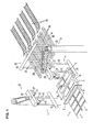
- Figure 1 is an overall perspective view of the apparatus for supplying bags to a packaging machine.
- a horizontal-type bag-making machine (only the cutter is shown) creates two rows of connected bags in which adjacent bags are joined at their respective side edges and two bags are fed out therefrom in parallel in the direction of the width of the bags (the horizontal-type bag-making machine being a two-row type).
- the bag mouth portions of the two simultaneously-fed bags face in the direction opposite to each other (facing outwardly).
- This type of horizontal-type bag-making machine is known and is described in, for example, Japanese Patent No.
- the packaging machine (not shown in the drawings, and as seen from the following description, only the groups of bags placed on the belt conveyor of a conveyor magazine-type bag-supply apparatus are illustrated) includes four conveyor magazine-type bag-supply apparatuses, and it takes up four bags at once and applies various types of package processing.
- This type of packaging machine is known as disclosed in, for example, Japanese Patent Application Laid-Open (Kokai) No. 2002-308223 .
- the horizontal-type bag-making machine and the packaging machine are installed such that the conveyance direction (left to right in the drawings) of the belt conveyors of the conveyor magazine-type bag-supply apparatuses matches the bag feed direction of the horizontal-type bag-making machine.
- the orientation of the bags manufactured by and fed out from the horizontal-type bag-making machine differs by 90 degrees from the orientation of the bags in the conveyor magazine-type bag-supply apparatuses (the orientation of bags to be supplied to the belt conveyors of the conveyor magazine-type bag-supply apparatuses), and the orientation of the bags fed out in parallel from the horizontal-type bag-making machine differs from each other by 180 degrees.
- the number of bags fed out from the horizontal-type bag-making machine at once is two
- the number of belt conveyors of the conveyor magazine-type bag-supply apparatuses is four (meaning four bags are supplied to the packaging machine at once).
- Figure 2 shows part of the horizontal-type bag-making machine 1 (only cutter 2 thereof is shown), positioning conveyor 3 and the first transportation means 4 and 5.
- Positioning conveyor 3 which positions, as seen from Figure 2 , bags 6a, 7a, 6b and 7b separated from the respective connected bags 6 and 7, is provided ahead (or on the downstream side) of the cutter 2.
- the positioning conveyor 3 is comprised of two small conveyors (or two sub-conveyors comprising a first conveyor 8 and a second conveyor 9) that are installed in series to each other and with the conveyance direction in parallel to (or the same as) the direction of transportation of the connected bags 6 and 7 in the horizontal-type bag-making machine 1.
- the first and second conveyors 8 and 9 are equipped with drive mechanisms (not shown) that are independent of each other; and they start to operate immediately after the action of the cutter 2 (for separating the respective bags) and then stop based on the detection signals from first detection sensors 11 and 12 and second detection sensors 13 and 14.
- the first and second conveyors 8 and 9 are set up so that they operate once in every two actions of the cutter 2.
- the bags 6a and 7a which have arrived on the belt of the first conveyor 8 and stopped there are cut off from the connected bags 6 and 7 by the cutter 2 (see Figure 3 ), and then the first and second conveyors 8 and 9 are operated so that the separated bags 6a and 7a are conveyed forward.
- the connected bags 6 and 7 start to move forward (toward the positioning conveyor 3), then stop, so that the next bags 6b and 7b are cut off from the connected bags 6 and 7 by the cutter 2 (see Figure 4 ).
- the first and second conveyors 8 and 9 stop when they receive the detection signals, so that the bags 6b and 7b are positioned at a prescribed location on the belt of the first conveyor 8, and the bags 6a and 7a are positioned at a prescribed location on the belt of the second conveyor 9.
- the space (distance between centers) P 0 between the positioned rows of the separated bags (bags 6a and 6b, bags 7a and 7b) on the positioning conveyor 3 (comprising the first and second conveyors 8 and 9) is set to be larger than the bag width W and to be the same as the space P between the adjacent supply conveyors 39 (or as the distance between centers of the adjacent supply conveyors 39), which are installed in parallel and will be described later.
- the positioning conveyor 3 is formed by two small conveyors (first and second conveyors (sub-conveyors) 8 and 9, each slightly larger than the size of one bag). If the number of bags set thereon is generally 2 rows x B (B: integer of 1 or 2 or greater), then the positioning conveyor 3 is comprised of B small conveyors (or sub-conveyors). So as to ensure the positioning precision of the bags (particularly, the space between the bags 6a and 7a cut first and the bags 6b and 7b cut next), it is desirable that the positioning conveyor 3 be formed by B small conveyors that respectively have independent drive mechanisms, and it is nonetheless possible that the positioning conveyor 3 is formed by only one conveyor. In addition, instead of controlling the stop of the first and second conveyors 8 and 9 by the first and second detection sensors 11 through 14 (for bag positioning control purposes), a stopper(s) that positions the bags by stopping them on the positioning conveyor can be used.
- First transportation means 4 and 5 are installed at symmetrical positions on either side of the first and second conveyors 8 and 9.
- first transportation means 4 and 5 have the same construction, and each one of them is, as best shown in Figure 2 , comprised of a rotation shaft 15 disposed parallel to the conveyance direction of the first and second conveyors 8 and 9, one pair of swing arms 16 fixed to the rotational shaft 15 so as to be vertical thereto, and suction members 17 installed at the curved tip ends of the swing arms 16.
- the suction members 17 are connected to a vacuum source or atmosphere, through switching valves (not shown), from the tubular swing arms 16.
- the rotation shaft 15 is powered by a drive source (not shown) so as to be able to rotate back and forth 90 degrees between the horizontal position and the vertical position.
- the swing arms 16 swing up and down in the vertical plane perpendicular to the direction of width of bags 6a, 6b, 7a and 7b (the feed direction of the connected bags 6 and 7) between the horizontal position shown in Figure 2 and the perpendicular position shown in Figure 3 .
- the bags are, as a result, changed from the horizontal attitude to the perpendicular attitude with the bag mouth portions facing down (the suction surfaces of the suction members 17 face the horizontal direction).
- the bag surfaces of bags 6a, 6b, 7a and 7b are within the plane parallel to the feed direction of the connected bags 6 and 7 (that matches the conveyance direction of the positioning conveyor 3), and the bag surfaces of the bags 6a and 6b face the bag surfaces of the bags 7a and 7b.
- the first transportation means 4 and 5 function symmetrically to each other.
- second transportation means 21 and 22 are installed at symmetrical positions near the first transportation means 4 and 5.
- each one of the second transportation means 21 and 22 has the same construction, and, as seen from Figure 4 , each one of the second transportation means 21 and 22 comprises a perpendicularly standing hollow support pillar 23, a hollow base shaft 20 which is rotatably provided in the support pillar 23 and rotate back and forth within a prescribed angle by being driven by a drive source (not shown) within a horizontal plane (see Figure 1 ).
- Each one of the second transportation means 21 and 22 further includes a transportation arm 24, which is fixed to the base shaft 20 so as to swing back and forth within a prescribed angle within the horizontal plane by the rotation of the base shaft 20, a support shaft 26a which is provided in the tip end of the transportation arm 24 so as to be rotatble within a horizontal plane.
- the support shaft 26a is provided with a supporting member 26 which is horizontally rotatable back and forth within a prescribed angle by a drive mechanism 25, and a pair of bag gripping members 27 are installed on the underneath of the supporting member 26.
- the drive mechanism 25 is comprised of a first pulley 28 fixed to the support shaft 26a, a second pulley 31 fixed to the rotation shaft 29 that is rotatably provided within the base shaft 20, a timing belt 32 provided between the two (first and second) pulleys 28 and 31, and a drive source (not shown) that drives (rotates) the rotation shaft 29 within a prescribed angle.
- the support shaft 26a is disposed at the center of the supporting member 26, and a pair of bag gripping members 27, which are for gripping the top edges (closed sides or bag bottoms) of the bags, whose bag mouth portion faces downward, from both sides, are installed on the underside of the supporting member 26 so that the bag gripping members 27 are on the left and right sides of the supporting member 26 with the support shaft 26a at the center.
- the bag gripping members 27 are opened and closed by a drive mechanism (not shown) and grip the bags when closed.
- the supporting members 26 are moved in the horizontal plane between a first position (see Figure 4 ) which is on the first transportation means 4 and 5 side and a second position (see Figure 5 ) which is on the third transportation means 35 (described below) side when the transportation arms 24 swing; and during this movement from the first position to the second position, they are respectively rotated about the support shafts 26a a prescribed angle with respect to the transportation arm 24.
- the transportation arms 24 and 24 and supporting members 26 and 26 of the second transportation means 21 and 22 are moved symmetrically to their counterpart.
- the bag surfaces of the bags 6a, 6b, 7a and 7b, which are held vertically by the first transportation means 4 and 5, are in a plane parallel to the conveyance direction of the positioning conveyor 3, and the gripping surfaces of the bag gripping members 27 and 27 of the supporting members 26 and 26 of the second transportation means 21 and 22 are also in a plane parallel to the conveyance direction of the positioning conveyor 3.
- the bags 6a, 6b, 7a and 7b are, as described above, rotated 90 degrees within the horizontal plane; however, since the supporting members 26 are rotated prescribed angles with respect to the transportation arms 24 when the transportation arms 24 swing, the angles of the swing of the transportation arms 24 can be set to considerably less than 90 degrees (if the supporting members 26 are installed so as not to be rotated with respect to the transportation arms 24, then the swing angles of the transportation arms 24 must be set to 90 degrees to make the bags 6a, 6b, 7a and 7b rotate 90 degrees).
- the space required for the second transportation means 21 and 22 can be decreased, and the degree of freedom in designing the conditions that the space between bags 6b and 7b is set to be equal to the space between bags 6a and 6b and to the space between bags 7a and 7b increases.
- the supporting members 26 and 26 of the second transportation means 21 and 22 are being moved from the position on the first transportation means 4 and 5 side to the position on the third transportation means 35 side (or from the first position in Figure 4 to the second position in Figure 5 ), the supporting member 26 of the second transportation means 21 is rotated to the right (clockwise) and the supporting member 26 of the second transportation means 22 is rotated the left (anticlockwise); accordingly, when the supporting members 26 and 26 are brought to the position on the third transportation means 35 side (or to the second position) shown in Figure 5 , the bag surfaces of the bags 6a, 6b, 7a and 7b that were facing upward (the bag surfaces that faced upward when the bags were on the positioning conveyor 3) face backward with respect to the conveyance direction of the positioning conveyor 3 (or face left side in Figure 5 ).
- the present invention can be set so that the supporting member 26 of the second transportation means 21 is rotated left (counterclockwise) and the supporting member 26 of the second transportation means 22 is rotated right (clockwise).
- the first and second transportation means are provided so that, for example, the swing arms 16 swing in the direction opposite from the positioning conveyor 3 after the gripping members 27 have gripped the bags, and then the swing arms 16 swing toward the positioning conveyor after the supporting member 26 of the second transportation means 21 has completed the counterclockwise rotation and the supporting member 26 of the second transportation means 22 has completed the clockwise rotation.
- the bags held by the gripping members 27 are, as a result, prevented from coming into contact with the swing arms 16 when the supporting members 26 are rotate
- the bag surfaces which face forward of the bags 6a, 6b, 7a and 7b held by the second transportation means 21 and 22 (or face the feed direction of the supply conveyors 39, which will be described below) at the second position which is on the third transportation means 35 side, face outwardly (or the outer side) of the packaging machine.
- bags are generally supplied to the packaging machine so that whichever side (front or back) of each of the bags on which printing is to be made faces the outer side of the packaging machine; and in the present invention, it is possible to print on either the front side or the back side of the bag by way of setting the rotation directions of the supporting members 26 and 26 differently as described above.
- the rotation of each one of the supporting members 26 with respect to the transportation arm 24 is made by the drive mechanism 25 that includes a drive source (not shown).
- the supporting members 26 can be designed so that they are, without using drive sources, rotated at a prescribed angle when the transportation arms 24 swing; and this can be done by fixing the pulleys 31 so as not to rotate relative to the support pillars 23 and by appropriately setting the pulley ratio between the pulleys 28 and the pulleys 31.
- the rotation angle and the rotation direction of the supporting member 26 with respect to the transportation arm 24 cannot be changed freely.
- the third transportation means 35 is provided near the second transportation means 21 and 22.
- the third transportation means 35 is comprised of a rotation shaft 36 disposed horizontally and at right angles with respect to the conveyance direction of the first and second conveyors 8 and 9, four swing arms 37 fixed perpendicularly to the rotation shaft 36, and suction members 38 installed at the tip ends of the swing arms 37.
- the suction members 38 are connected to a vacuum source or atmosphere via the tubular swing arms 37 with switching valves (not shown) in between.
- the rotation shaft 36 is rotated back and forth 90 degrees by a drive source (not shown); and by this rotation of the rotation shaft 36, the swing arms 37 swing up and down in a perpendicular plane parallel to the conveyance direction of the positioning conveyor 3 (or in the same direction as the conveyance direction of the supply conveyors 39) so that they take the perpendicular position shown in Figure 6 and the horizontal position shown in Figure 7 .
- four sets of supply conveyors 39 corresponding to the suction members 38 of the third transportation means 35 are installed near the third transportation means 35.
- the conveyance direction of the four sets of supply conveyors 39 matches the direction the bag mouth portions of the bags 6a, 6b, 7a and 7b, which are held by third transportation means 35 and placed on supply conveyors 39, face.
- Each of the supply conveyors 39 is comprised of a pair of conveyor belts 41 and 42 with a prescribed distance in between, and the bags 6a, 6b, 7a and 7b placed on the supply conveyors 39 are conveyed forward with their bag mouth portions facing forward (rightward in Figure 7 ).
- conveyor magazine-type bag-supply apparatuses 43 which are known widely are installed.
- the conveyor magazine-type bag-supply apparatus 43 is not shown in the drawings, and in lieu thereof only bag groups (multiple bags) C, in which upper bags are offset sequentially in the direction of the bag mouth portions on the belt conveyor, which is a part of each conveyor magazine-type bag-supply apparatus 43, with the bag mouth portions facing forward, are shown in Figures 1 and 6 through 8 .
- each bag at the rear end of each bag group C is lifted up by an arm (not shown) in synchronous with the bag being fed from the supply conveyors 39 (see Japanese Patent Application Laid-Open (Kokai) No. 8-337217 ), and each of the bags 6a, 6b, 7a and 7b on the supply conveyors 39 is fed into the space between the belt conveyors of the conveyor magazine-type bag-supply apparatuses 43 and the above-described rear-end bag.
- the horizontal-type bag-making machine is a two-row type
- the orientation of the bags manufactured and fed out therefrom is different by 90 degrees from the orientation of the bags in the conveyor magazine-type bag-supply apparatuses
- the orientation of the bags fed out in two rows in parallel are different by 180 degrees
- the number of the belt conveyors of the conveyor magazine-type bag-supply apparatuses are four (four bags are transported at once).
- the present invention needless to say, can be generally applied to other combinations of horizontal-type bag-making machines and packaging machines.
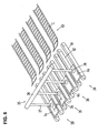
- the first difference is that the conveyance distance of the small conveyors 8 and 9 (or the length in the conveyance direction of the small conveyors 8 and 9), which make the positioning conveyor 3, are shorter than in the apparatus shown in Figure 1 , and the space of the bags between the row of the bags 6a and 6b positioned on the small conveyors 8 and 9 (or the space between the bags 7a and 7b) P 0 is set to be greater (wider) than the bag width W (P 0 > W) but smaller (narrower) than the space P of the supply conveyors 39 (P 0 ⁇ P) that are provided in parallel.
- the space between the suction members 17 and 17 of the first transportation means 4 and 5 is set so as to be variable between P 0 and P.
- the swing arms 16 and 16 of the first transportation means 4 and 5 are provided on different rotation shafts 15a and 15b, and the rotation shafts 15a and 15b are movable back and forth in opposite directions to each other in their axial direction as the rotation shafts 15a and 15b are rotated by a mechanism which is not shown in Figure 9 .
- the swing arms 16 and 16 swing between the perpendicular position and the horizontal position and, at the same time, move closer to and away from each other, and the suction members 17 and 17 at the tip ends of the swing arms 16 are also moved closer to and away from each other.
- the conveyance distance of the bags 6a, 6b, 7a and 7b on the small conveyors 8 and 9 that make the positioning conveyor 3 can be shorten, and the time for positioning the bags 6a, 6b, 7a and 7b can be shorten as well; and thus it is possible to increase the bag supply speed.
- the space between the suction members 17 and 17 of the first transportation means 4 and 5 is made to widen when the suction members 17 are brought to the perpendicular position.
- all it is required in this setting is that the bags 6a, 6b, 7a and 7b positioned at space distance P 0 are transported to the supply conveyors 39 at ultimate space P; accordingly, it is also possible that the space distance between the bag gripping members 27 of the second transportation means 21 and 22 or the space distance between the suction members 38 of the third transportation means 35 is made to widen; and further, more than one of the spaces comprising the space between the suction members 17 and 17 of the first transportation means 4 and 5, the space between the bag gripping members 27 and 27 of the second transportation means 21 and 22, and the space between the four suction members 38 of the third transportation means 35 can be made to widen during the bag transportation.
- the second difference of the bag supply apparatus of Figure 9 from the bag supply apparatus of Figure 1 is that the supply conveyors 39 of the bag supply apparatus of Figure 9 use conveyance mechanisms that include a pair of feed pins 45.
- each supply conveyor 39 is provided with a flat frame 46 (commonly used for all supply conveyors 39) installed on a machine base (not shown), a pair of feed pins 45, a pair of guide plates 47 fixed to the frame 46 that guide bags at two edges thereof, an elevator mechanism (not shown) that raises and lowers the feed pins 45, and a moving mechanism (not shown) that moves the feed pins 45 forward and backward.
- the top surface of a part (a bag support plate 48) that is between the pair of (or two) guide plates 47 on the flat frame 46 makes the bag conveyance surface.
- a pair of groove openings 49 are formed on the left and right sides of each bag support plate 48 so that the feed pins 45 are projected out therefrom and moved forward and backward in the groove openings 49.
- the moving mechanism advances (or moves rightward) the feed pins 45, bringing the feed pins into contact with the rear end of each of the bags 6a, 6b, 7a and 7b on the bag support base 48, and then the bags 6a, 6b, 7a and 7b are conveyed toward the belt conveyors of the conveyor magazine-type bag-supply apparatuses 43.
- the elevator mechanism lowers the feed pins 45 below the conveyance surface of the bag support plate 48 and the moving mechanism returns the feed pins 45 to their original positions.
Landscapes
- Engineering & Computer Science (AREA)
- Mechanical Engineering (AREA)
- Supplying Of Containers To The Packaging Station (AREA)
- Specific Conveyance Elements (AREA)
- Sheets, Magazines, And Separation Thereof (AREA)
Applications Claiming Priority (1)
| Application Number | Priority Date | Filing Date | Title |
|---|---|---|---|
| JP2008331688A JP5148469B2 (ja) | 2008-12-26 | 2008-12-26 | 包装機への袋供給方法及び装置 |
Publications (3)
| Publication Number | Publication Date |
|---|---|
| EP2204280A2 true EP2204280A2 (fr) | 2010-07-07 |
| EP2204280A3 EP2204280A3 (fr) | 2015-09-09 |
| EP2204280B1 EP2204280B1 (fr) | 2016-10-19 |
Family
ID=42115327
Family Applications (1)
| Application Number | Title | Priority Date | Filing Date |
|---|---|---|---|
| EP09015916.1A Not-in-force EP2204280B1 (fr) | 2008-12-26 | 2009-12-23 | Procédé et appareil d'alimentation de sacs dans une machine d'emballage |
Country Status (4)
| Country | Link |
|---|---|
| US (1) | US8511458B2 (fr) |
| EP (1) | EP2204280B1 (fr) |
| JP (1) | JP5148469B2 (fr) |
| ES (1) | ES2600228T3 (fr) |
Cited By (2)
| Publication number | Priority date | Publication date | Assignee | Title |
|---|---|---|---|---|
| CN105836416A (zh) * | 2016-06-09 | 2016-08-10 | 屈珠丽 | 一种菜籽收购后储存传送装置 |
| CN111746860A (zh) * | 2020-06-29 | 2020-10-09 | 重庆医药高等专科学校 | 袋式颗粒药品密封包装机 |
Families Citing this family (10)
| Publication number | Priority date | Publication date | Assignee | Title |
|---|---|---|---|---|
| US10988293B2 (en) * | 2011-03-17 | 2021-04-27 | The Jel Sert Company | Flexible tubular package for edible product |
| JP2013091498A (ja) * | 2011-10-24 | 2013-05-16 | Furukawa Mfg Co Ltd | 包装袋の袋口開口機構 |
| CN103803119B (zh) * | 2013-01-17 | 2016-04-27 | 常州先进制造技术研究所 | 自动连续供袋装置 |
| JP6746192B2 (ja) * | 2014-11-17 | 2020-08-26 | 不二精機株式会社 | 棒状寿司の包装方法 |
| US10919252B2 (en) * | 2016-01-19 | 2021-02-16 | S. C. Johnson & Son, Inc. | System and process for making a pouch or container |
| CN112390014A (zh) * | 2019-08-19 | 2021-02-23 | 张家港爱丽家居科技股份有限公司 | 一种物料整合设备 |
| IT202000012166A1 (it) * | 2020-05-25 | 2021-11-25 | Perfect Pack S R L | Macchina confezionatrice |
| JP2023045411A (ja) * | 2021-09-22 | 2023-04-03 | ゼネラルパッカー株式会社 | 包装袋連続体を使用した給袋方法 |
| JP2023045412A (ja) * | 2021-09-22 | 2023-04-03 | ゼネラルパッカー株式会社 | 給袋装置およびそれを備えた給袋包装機 |
| CN114751038B (zh) * | 2022-05-25 | 2022-11-15 | 广州维纳斯智能科技股份有限公司 | 滑轨自动化组装生产线 |
Citations (7)
| Publication number | Priority date | Publication date | Assignee | Title |
|---|---|---|---|---|
| JPH08337217A (ja) | 1995-06-09 | 1996-12-24 | Toyo Jidoki Co Ltd | 包装材補給装置 |
| JP3105568B2 (ja) | 1991-05-17 | 2000-11-06 | 株式会社トマック | 2列に搬出された袋束を1列掛包装装置に供給する供給装置 |
| JP2002308223A (ja) | 2001-04-13 | 2002-10-23 | Toyo Jidoki Co Ltd | 連続移送式袋詰め包装機における空袋供給装置及び製品袋取出装置 |
| JP2004042447A (ja) | 2002-07-11 | 2004-02-12 | Toyo Jidoki Co Ltd | ストッカー装置付き製袋包装機 |
| JP2004244085A (ja) | 2003-02-17 | 2004-09-02 | Toyo Jidoki Co Ltd | 製袋包装機 |
| JP2006111346A (ja) | 2004-09-15 | 2006-04-27 | Toyo Jidoki Co Ltd | 空袋群供給方法及び空袋群供給装置 |
| JP3840255B2 (ja) | 2004-05-18 | 2006-11-01 | トタニ技研工業株式会社 | 製袋機 |
Family Cites Families (13)
| Publication number | Priority date | Publication date | Assignee | Title |
|---|---|---|---|---|
| US2125758A (en) * | 1935-05-08 | 1938-08-02 | Harry F Waters | Machine for manufacturing bags |
| JPS60154318U (ja) * | 1984-03-22 | 1985-10-15 | 株式会社 日型 | 被移送物の間隔変換装置 |
| IT1192822B (it) * | 1985-07-11 | 1988-05-12 | Kureha Chemical Ind Co Ltd | Impianto automatico di riempimento e di confezionamento |
| JPH0246728U (fr) * | 1988-09-22 | 1990-03-30 | ||
| JPH03105568A (ja) | 1989-09-20 | 1991-05-02 | Hitachi Ltd | 2次元3次元統合型cadシステム |
| JP3015568B2 (ja) * | 1991-12-26 | 2000-03-06 | 三菱重工業株式会社 | 排ガス処理用触媒 |
| JPH0751310Y2 (ja) * | 1991-09-13 | 1995-11-22 | 株式会社コムテック | 製袋機の袋排出装置 |
| DE4141466A1 (de) * | 1991-12-16 | 1993-06-17 | Windmoeller & Hoelscher | Verfahren zur herstellung von beuteln und vorrichtung zum durchfuehren dieses verfahrens |
| US5335478A (en) * | 1993-01-08 | 1994-08-09 | Aronsen Arthur N | Multi-compartment dispenser pouch and method of making |
| JPH08295315A (ja) * | 1995-04-25 | 1996-11-12 | Toyo Seikan Kaisha Ltd | 袋自動取出供給装置及び該装置で使用する袋輸送マガジン |
| US6416453B1 (en) * | 1999-04-12 | 2002-07-09 | Ro-An Industries Corp. | Seal bar mechanism for bag machines |
| JP4905979B2 (ja) * | 2007-07-10 | 2012-03-28 | 東洋自動機株式会社 | 包装機への袋供給方法及び装置 |
| DE102008007737A1 (de) * | 2008-02-05 | 2009-08-06 | Focke & Co.(Gmbh & Co. Kg) | Vorrichtung zum Handhaben von (Tabak-) Beuteln |
-
2008
- 2008-12-26 JP JP2008331688A patent/JP5148469B2/ja active Active
-
2009
- 2009-12-18 US US12/655,035 patent/US8511458B2/en active Active
- 2009-12-23 ES ES09015916.1T patent/ES2600228T3/es active Active
- 2009-12-23 EP EP09015916.1A patent/EP2204280B1/fr not_active Not-in-force
Patent Citations (7)
| Publication number | Priority date | Publication date | Assignee | Title |
|---|---|---|---|---|
| JP3105568B2 (ja) | 1991-05-17 | 2000-11-06 | 株式会社トマック | 2列に搬出された袋束を1列掛包装装置に供給する供給装置 |
| JPH08337217A (ja) | 1995-06-09 | 1996-12-24 | Toyo Jidoki Co Ltd | 包装材補給装置 |
| JP2002308223A (ja) | 2001-04-13 | 2002-10-23 | Toyo Jidoki Co Ltd | 連続移送式袋詰め包装機における空袋供給装置及び製品袋取出装置 |
| JP2004042447A (ja) | 2002-07-11 | 2004-02-12 | Toyo Jidoki Co Ltd | ストッカー装置付き製袋包装機 |
| JP2004244085A (ja) | 2003-02-17 | 2004-09-02 | Toyo Jidoki Co Ltd | 製袋包装機 |
| JP3840255B2 (ja) | 2004-05-18 | 2006-11-01 | トタニ技研工業株式会社 | 製袋機 |
| JP2006111346A (ja) | 2004-09-15 | 2006-04-27 | Toyo Jidoki Co Ltd | 空袋群供給方法及び空袋群供給装置 |
Cited By (3)
| Publication number | Priority date | Publication date | Assignee | Title |
|---|---|---|---|---|
| CN105836416A (zh) * | 2016-06-09 | 2016-08-10 | 屈珠丽 | 一种菜籽收购后储存传送装置 |
| CN105836416B (zh) * | 2016-06-09 | 2017-11-21 | 新昌县盛金祺机械有限公司 | 一种菜籽收购后储存传送装置 |
| CN111746860A (zh) * | 2020-06-29 | 2020-10-09 | 重庆医药高等专科学校 | 袋式颗粒药品密封包装机 |
Also Published As
| Publication number | Publication date |
|---|---|
| US8511458B2 (en) | 2013-08-20 |
| JP5148469B2 (ja) | 2013-02-20 |
| EP2204280B1 (fr) | 2016-10-19 |
| EP2204280A3 (fr) | 2015-09-09 |
| ES2600228T3 (es) | 2017-02-07 |
| US20100162664A1 (en) | 2010-07-01 |
| JP2010149906A (ja) | 2010-07-08 |
Similar Documents
| Publication | Publication Date | Title |
|---|---|---|
| EP2204280B1 (fr) | Procédé et appareil d'alimentation de sacs dans une machine d'emballage | |
| EP2014558B1 (fr) | Procédé et appareil d'alimentation de sacs dans une machine d'emballage | |
| JP6552947B2 (ja) | 包装機及び包装方法 | |
| TWI452003B (zh) | 玻璃基板捆包裝置及其捆包方法 | |
| US8122692B2 (en) | Empty bag supply method and empty bag supply apparatus | |
| JP2000313412A (ja) | 箱詰めシステムにおける製品振り分け機構 | |
| JP2006256744A (ja) | 容器整列装置 | |
| JP5911281B2 (ja) | 開袋装置 | |
| JP4607654B2 (ja) | スパウト装着方法 | |
| JP4866202B2 (ja) | スパウト装着装置 | |
| JP5604211B2 (ja) | 物品移し替え装置 | |
| JP7029055B2 (ja) | 物品積層装置 | |
| JP4866197B2 (ja) | スパウト装着装置 | |
| JP4392535B2 (ja) | ブランクシートの供給装置 | |
| JP4345006B2 (ja) | ブランクシートの折曲げ搬送装置 | |
| JP2023104582A (ja) | 搬送装置 | |
| JP2004189423A (ja) | 集積搬送装置 | |
| JP4131329B2 (ja) | シートマガジンにおけるシート分離装置 | |
| JP2018002364A (ja) | 容器処理装置 | |
| JP2007091416A (ja) | 搬送装置 | |
| JPS6246860A (ja) | シ−ト材料の搬出方法及びその装置 | |
| JP2006137456A (ja) | 搬送装置及びそれを備えた箱詰め装置 | |
| JP2018076158A (ja) | 積層装置 | |
| JP2000109226A (ja) | シート状部材の供給装置および供給方法 | |
| JPH08310501A (ja) | 袋詰め封止装置 |
Legal Events
| Date | Code | Title | Description |
|---|---|---|---|
| PUAI | Public reference made under article 153(3) epc to a published international application that has entered the european phase |
Free format text: ORIGINAL CODE: 0009012 |
|
| AK | Designated contracting states |
Kind code of ref document: A2 Designated state(s): AT BE BG CH CY CZ DE DK EE ES FI FR GB GR HR HU IE IS IT LI LT LU LV MC MK MT NL NO PL PT RO SE SI SK SM TR |
|
| AX | Request for extension of the european patent |
Extension state: AL BA RS |
|
| PUAL | Search report despatched |
Free format text: ORIGINAL CODE: 0009013 |
|
| AK | Designated contracting states |
Kind code of ref document: A3 Designated state(s): AT BE BG CH CY CZ DE DK EE ES FI FR GB GR HR HU IE IS IT LI LT LU LV MC MK MT NL NO PL PT RO SE SI SK SM TR |
|
| AX | Request for extension of the european patent |
Extension state: AL BA RS |
|
| RIC1 | Information provided on ipc code assigned before grant |
Ipc: B31B 19/96 20060101AFI20150804BHEP Ipc: B65B 43/12 20060101ALI20150804BHEP Ipc: B65B 43/04 20060101ALI20150804BHEP |
|
| 17P | Request for examination filed |
Effective date: 20160309 |
|
| RBV | Designated contracting states (corrected) |
Designated state(s): AT BE BG CH CY CZ DE DK EE ES FI FR GB GR HR HU IE IS IT LI LT LU LV MC MK MT NL NO PL PT RO SE SI SK SM TR |
|
| GRAP | Despatch of communication of intention to grant a patent |
Free format text: ORIGINAL CODE: EPIDOSNIGR1 |
|
| INTG | Intention to grant announced |
Effective date: 20160509 |
|
| GRAS | Grant fee paid |
Free format text: ORIGINAL CODE: EPIDOSNIGR3 |
|
| GRAA | (expected) grant |
Free format text: ORIGINAL CODE: 0009210 |
|
| AK | Designated contracting states |
Kind code of ref document: B1 Designated state(s): AT BE BG CH CY CZ DE DK EE ES FI FR GB GR HR HU IE IS IT LI LT LU LV MC MK MT NL NO PL PT RO SE SI SK SM TR |
|
| REG | Reference to a national code |
Ref country code: GB Ref legal event code: FG4D |
|
| REG | Reference to a national code |
Ref country code: CH Ref legal event code: EP |
|
| REG | Reference to a national code |
Ref country code: FR Ref legal event code: PLFP Year of fee payment: 8 |
|
| REG | Reference to a national code |
Ref country code: AT Ref legal event code: REF Ref document number: 837972 Country of ref document: AT Kind code of ref document: T Effective date: 20161115 |
|
| REG | Reference to a national code |
Ref country code: IE Ref legal event code: FG4D |
|
| REG | Reference to a national code |
Ref country code: DE Ref legal event code: R079 Ref document number: 602009041787 Country of ref document: DE Free format text: PREVIOUS MAIN CLASS: B31B0019960000 Ipc: B31B0070960000 |
|
| REG | Reference to a national code |
Ref country code: DE Ref legal event code: R096 Ref document number: 602009041787 Country of ref document: DE |
|
| REG | Reference to a national code |
Ref country code: ES Ref legal event code: FG2A Ref document number: 2600228 Country of ref document: ES Kind code of ref document: T3 Effective date: 20170207 |
|
| REG | Reference to a national code |
Ref country code: NL Ref legal event code: MP Effective date: 20161019 |
|
| REG | Reference to a national code |
Ref country code: LT Ref legal event code: MG4D |
|
| PG25 | Lapsed in a contracting state [announced via postgrant information from national office to epo] |
Ref country code: LV Free format text: LAPSE BECAUSE OF FAILURE TO SUBMIT A TRANSLATION OF THE DESCRIPTION OR TO PAY THE FEE WITHIN THE PRESCRIBED TIME-LIMIT Effective date: 20161019 |
|
| REG | Reference to a national code |
Ref country code: AT Ref legal event code: MK05 Ref document number: 837972 Country of ref document: AT Kind code of ref document: T Effective date: 20161019 |
|
| PG25 | Lapsed in a contracting state [announced via postgrant information from national office to epo] |
Ref country code: NO Free format text: LAPSE BECAUSE OF FAILURE TO SUBMIT A TRANSLATION OF THE DESCRIPTION OR TO PAY THE FEE WITHIN THE PRESCRIBED TIME-LIMIT Effective date: 20170119 Ref country code: GR Free format text: LAPSE BECAUSE OF FAILURE TO SUBMIT A TRANSLATION OF THE DESCRIPTION OR TO PAY THE FEE WITHIN THE PRESCRIBED TIME-LIMIT Effective date: 20170120 Ref country code: LT Free format text: LAPSE BECAUSE OF FAILURE TO SUBMIT A TRANSLATION OF THE DESCRIPTION OR TO PAY THE FEE WITHIN THE PRESCRIBED TIME-LIMIT Effective date: 20161019 Ref country code: SE Free format text: LAPSE BECAUSE OF FAILURE TO SUBMIT A TRANSLATION OF THE DESCRIPTION OR TO PAY THE FEE WITHIN THE PRESCRIBED TIME-LIMIT Effective date: 20161019 |
|
| PG25 | Lapsed in a contracting state [announced via postgrant information from national office to epo] |
Ref country code: PL Free format text: LAPSE BECAUSE OF FAILURE TO SUBMIT A TRANSLATION OF THE DESCRIPTION OR TO PAY THE FEE WITHIN THE PRESCRIBED TIME-LIMIT Effective date: 20161019 Ref country code: BE Free format text: LAPSE BECAUSE OF FAILURE TO SUBMIT A TRANSLATION OF THE DESCRIPTION OR TO PAY THE FEE WITHIN THE PRESCRIBED TIME-LIMIT Effective date: 20161019 Ref country code: HR Free format text: LAPSE BECAUSE OF FAILURE TO SUBMIT A TRANSLATION OF THE DESCRIPTION OR TO PAY THE FEE WITHIN THE PRESCRIBED TIME-LIMIT Effective date: 20161019 Ref country code: FI Free format text: LAPSE BECAUSE OF FAILURE TO SUBMIT A TRANSLATION OF THE DESCRIPTION OR TO PAY THE FEE WITHIN THE PRESCRIBED TIME-LIMIT Effective date: 20161019 Ref country code: NL Free format text: LAPSE BECAUSE OF FAILURE TO SUBMIT A TRANSLATION OF THE DESCRIPTION OR TO PAY THE FEE WITHIN THE PRESCRIBED TIME-LIMIT Effective date: 20161019 Ref country code: PT Free format text: LAPSE BECAUSE OF FAILURE TO SUBMIT A TRANSLATION OF THE DESCRIPTION OR TO PAY THE FEE WITHIN THE PRESCRIBED TIME-LIMIT Effective date: 20170220 Ref country code: AT Free format text: LAPSE BECAUSE OF FAILURE TO SUBMIT A TRANSLATION OF THE DESCRIPTION OR TO PAY THE FEE WITHIN THE PRESCRIBED TIME-LIMIT Effective date: 20161019 Ref country code: IS Free format text: LAPSE BECAUSE OF FAILURE TO SUBMIT A TRANSLATION OF THE DESCRIPTION OR TO PAY THE FEE WITHIN THE PRESCRIBED TIME-LIMIT Effective date: 20170219 |
|
| REG | Reference to a national code |
Ref country code: DE Ref legal event code: R097 Ref document number: 602009041787 Country of ref document: DE |
|
| PG25 | Lapsed in a contracting state [announced via postgrant information from national office to epo] |
Ref country code: DK Free format text: LAPSE BECAUSE OF FAILURE TO SUBMIT A TRANSLATION OF THE DESCRIPTION OR TO PAY THE FEE WITHIN THE PRESCRIBED TIME-LIMIT Effective date: 20161019 Ref country code: EE Free format text: LAPSE BECAUSE OF FAILURE TO SUBMIT A TRANSLATION OF THE DESCRIPTION OR TO PAY THE FEE WITHIN THE PRESCRIBED TIME-LIMIT Effective date: 20161019 Ref country code: CZ Free format text: LAPSE BECAUSE OF FAILURE TO SUBMIT A TRANSLATION OF THE DESCRIPTION OR TO PAY THE FEE WITHIN THE PRESCRIBED TIME-LIMIT Effective date: 20161019 Ref country code: RO Free format text: LAPSE BECAUSE OF FAILURE TO SUBMIT A TRANSLATION OF THE DESCRIPTION OR TO PAY THE FEE WITHIN THE PRESCRIBED TIME-LIMIT Effective date: 20161019 Ref country code: SK Free format text: LAPSE BECAUSE OF FAILURE TO SUBMIT A TRANSLATION OF THE DESCRIPTION OR TO PAY THE FEE WITHIN THE PRESCRIBED TIME-LIMIT Effective date: 20161019 |
|
| REG | Reference to a national code |
Ref country code: CH Ref legal event code: PL |
|
| REG | Reference to a national code |
Ref country code: DE Ref legal event code: R082 Ref document number: 602009041787 Country of ref document: DE Representative=s name: KEIL & SCHAAFHAUSEN PATENTANWAELTE PARTGMBB, DE Ref country code: DE Ref legal event code: R082 Ref document number: 602009041787 Country of ref document: DE Representative=s name: KEIL & SCHAAFHAUSEN PATENT- UND RECHTSANWAELTE, DE |
|
| PLBE | No opposition filed within time limit |
Free format text: ORIGINAL CODE: 0009261 |
|
| STAA | Information on the status of an ep patent application or granted ep patent |
Free format text: STATUS: NO OPPOSITION FILED WITHIN TIME LIMIT |
|
| PG25 | Lapsed in a contracting state [announced via postgrant information from national office to epo] |
Ref country code: BG Free format text: LAPSE BECAUSE OF FAILURE TO SUBMIT A TRANSLATION OF THE DESCRIPTION OR TO PAY THE FEE WITHIN THE PRESCRIBED TIME-LIMIT Effective date: 20170119 Ref country code: SM Free format text: LAPSE BECAUSE OF FAILURE TO SUBMIT A TRANSLATION OF THE DESCRIPTION OR TO PAY THE FEE WITHIN THE PRESCRIBED TIME-LIMIT Effective date: 20161019 |
|
| 26N | No opposition filed |
Effective date: 20170720 |
|
| PG25 | Lapsed in a contracting state [announced via postgrant information from national office to epo] |
Ref country code: MC Free format text: LAPSE BECAUSE OF FAILURE TO SUBMIT A TRANSLATION OF THE DESCRIPTION OR TO PAY THE FEE WITHIN THE PRESCRIBED TIME-LIMIT Effective date: 20161019 |
|
| REG | Reference to a national code |
Ref country code: IE Ref legal event code: MM4A |
|
| PG25 | Lapsed in a contracting state [announced via postgrant information from national office to epo] |
Ref country code: LI Free format text: LAPSE BECAUSE OF NON-PAYMENT OF DUE FEES Effective date: 20161231 Ref country code: CH Free format text: LAPSE BECAUSE OF NON-PAYMENT OF DUE FEES Effective date: 20161231 Ref country code: LU Free format text: LAPSE BECAUSE OF NON-PAYMENT OF DUE FEES Effective date: 20161223 |
|
| PG25 | Lapsed in a contracting state [announced via postgrant information from national office to epo] |
Ref country code: SI Free format text: LAPSE BECAUSE OF FAILURE TO SUBMIT A TRANSLATION OF THE DESCRIPTION OR TO PAY THE FEE WITHIN THE PRESCRIBED TIME-LIMIT Effective date: 20161019 Ref country code: IE Free format text: LAPSE BECAUSE OF NON-PAYMENT OF DUE FEES Effective date: 20161223 |
|
| REG | Reference to a national code |
Ref country code: FR Ref legal event code: PLFP Year of fee payment: 9 |
|
| PG25 | Lapsed in a contracting state [announced via postgrant information from national office to epo] |
Ref country code: CY Free format text: LAPSE BECAUSE OF FAILURE TO SUBMIT A TRANSLATION OF THE DESCRIPTION OR TO PAY THE FEE WITHIN THE PRESCRIBED TIME-LIMIT Effective date: 20161019 Ref country code: HU Free format text: LAPSE BECAUSE OF FAILURE TO SUBMIT A TRANSLATION OF THE DESCRIPTION OR TO PAY THE FEE WITHIN THE PRESCRIBED TIME-LIMIT; INVALID AB INITIO Effective date: 20091223 |
|
| PG25 | Lapsed in a contracting state [announced via postgrant information from national office to epo] |
Ref country code: MK Free format text: LAPSE BECAUSE OF FAILURE TO SUBMIT A TRANSLATION OF THE DESCRIPTION OR TO PAY THE FEE WITHIN THE PRESCRIBED TIME-LIMIT Effective date: 20161019 Ref country code: TR Free format text: LAPSE BECAUSE OF FAILURE TO SUBMIT A TRANSLATION OF THE DESCRIPTION OR TO PAY THE FEE WITHIN THE PRESCRIBED TIME-LIMIT Effective date: 20161019 |
|
| PG25 | Lapsed in a contracting state [announced via postgrant information from national office to epo] |
Ref country code: MT Free format text: LAPSE BECAUSE OF NON-PAYMENT OF DUE FEES Effective date: 20161223 |
|
| PGFP | Annual fee paid to national office [announced via postgrant information from national office to epo] |
Ref country code: GB Payment date: 20201223 Year of fee payment: 12 Ref country code: FR Payment date: 20201223 Year of fee payment: 12 Ref country code: DE Payment date: 20201211 Year of fee payment: 12 |
|
| PGFP | Annual fee paid to national office [announced via postgrant information from national office to epo] |
Ref country code: IT Payment date: 20201224 Year of fee payment: 12 |
|
| PGFP | Annual fee paid to national office [announced via postgrant information from national office to epo] |
Ref country code: ES Payment date: 20210223 Year of fee payment: 12 |
|
| REG | Reference to a national code |
Ref country code: DE Ref legal event code: R119 Ref document number: 602009041787 Country of ref document: DE |
|
| GBPC | Gb: european patent ceased through non-payment of renewal fee |
Effective date: 20211223 |
|
| PG25 | Lapsed in a contracting state [announced via postgrant information from national office to epo] |
Ref country code: GB Free format text: LAPSE BECAUSE OF NON-PAYMENT OF DUE FEES Effective date: 20211223 Ref country code: DE Free format text: LAPSE BECAUSE OF NON-PAYMENT OF DUE FEES Effective date: 20220701 |
|
| PG25 | Lapsed in a contracting state [announced via postgrant information from national office to epo] |
Ref country code: FR Free format text: LAPSE BECAUSE OF NON-PAYMENT OF DUE FEES Effective date: 20211231 |
|
| PG25 | Lapsed in a contracting state [announced via postgrant information from national office to epo] |
Ref country code: IT Free format text: LAPSE BECAUSE OF NON-PAYMENT OF DUE FEES Effective date: 20211223 |
|
| REG | Reference to a national code |
Ref country code: ES Ref legal event code: FD2A Effective date: 20230330 |
|
| PG25 | Lapsed in a contracting state [announced via postgrant information from national office to epo] |
Ref country code: ES Free format text: LAPSE BECAUSE OF NON-PAYMENT OF DUE FEES Effective date: 20211224 |