EP2203113B1 - Diagnostische sensoreinheit - Google Patents
Diagnostische sensoreinheit Download PDFInfo
- Publication number
- EP2203113B1 EP2203113B1 EP08801909.6A EP08801909A EP2203113B1 EP 2203113 B1 EP2203113 B1 EP 2203113B1 EP 08801909 A EP08801909 A EP 08801909A EP 2203113 B1 EP2203113 B1 EP 2203113B1
- Authority
- EP
- European Patent Office
- Prior art keywords
- unit
- sensor
- radiation
- sensor unit
- measurement
- Prior art date
- Legal status (The legal status is an assumption and is not a legal conclusion. Google has not performed a legal analysis and makes no representation as to the accuracy of the status listed.)
- Active
Links
- 230000005855 radiation Effects 0.000 claims description 109
- 238000005259 measurement Methods 0.000 claims description 78
- 230000003287 optical effect Effects 0.000 claims description 36
- 238000011156 evaluation Methods 0.000 claims description 27
- 238000002847 impedance measurement Methods 0.000 claims description 16
- 238000001514 detection method Methods 0.000 claims description 5
- 239000004020 conductor Substances 0.000 claims description 4
- 230000001678 irradiating effect Effects 0.000 claims description 4
- 238000004891 communication Methods 0.000 claims description 3
- 239000011888 foil Substances 0.000 claims description 3
- 230000002787 reinforcement Effects 0.000 claims 1
- 210000001519 tissue Anatomy 0.000 description 67
- 229910052760 oxygen Inorganic materials 0.000 description 34
- 239000001301 oxygen Substances 0.000 description 34
- WQZGKKKJIJFFOK-GASJEMHNSA-N Glucose Natural products OC[C@H]1OC(O)[C@H](O)[C@@H](O)[C@@H]1O WQZGKKKJIJFFOK-GASJEMHNSA-N 0.000 description 33
- 239000008103 glucose Substances 0.000 description 33
- QVGXLLKOCUKJST-UHFFFAOYSA-N atomic oxygen Chemical compound [O] QVGXLLKOCUKJST-UHFFFAOYSA-N 0.000 description 30
- 210000004369 blood Anatomy 0.000 description 28
- 239000008280 blood Substances 0.000 description 28
- 230000036284 oxygen consumption Effects 0.000 description 17
- 230000004060 metabolic process Effects 0.000 description 11
- 238000004519 manufacturing process Methods 0.000 description 10
- 239000013307 optical fiber Substances 0.000 description 9
- 108010054147 Hemoglobins Proteins 0.000 description 8
- 102000001554 Hemoglobins Human genes 0.000 description 8
- 238000004458 analytical method Methods 0.000 description 8
- 230000036772 blood pressure Effects 0.000 description 8
- 230000002503 metabolic effect Effects 0.000 description 8
- 239000000203 mixture Substances 0.000 description 8
- 108010064719 Oxyhemoglobins Proteins 0.000 description 7
- 230000017531 blood circulation Effects 0.000 description 7
- 230000000875 corresponding effect Effects 0.000 description 7
- 238000012545 processing Methods 0.000 description 7
- 210000003491 skin Anatomy 0.000 description 7
- 208000037265 diseases, disorders, signs and symptoms Diseases 0.000 description 6
- 239000003925 fat Substances 0.000 description 6
- 235000013305 food Nutrition 0.000 description 6
- 230000037406 food intake Effects 0.000 description 6
- 230000006870 function Effects 0.000 description 6
- 238000000034 method Methods 0.000 description 6
- 230000001419 dependent effect Effects 0.000 description 5
- 201000010099 disease Diseases 0.000 description 5
- 235000012631 food intake Nutrition 0.000 description 5
- 230000010354 integration Effects 0.000 description 5
- 230000031700 light absorption Effects 0.000 description 5
- 230000010412 perfusion Effects 0.000 description 5
- 230000003595 spectral effect Effects 0.000 description 5
- 230000005540 biological transmission Effects 0.000 description 4
- 150000001720 carbohydrates Chemical class 0.000 description 4
- 235000014633 carbohydrates Nutrition 0.000 description 4
- 230000008859 change Effects 0.000 description 4
- 238000012937 correction Methods 0.000 description 4
- 238000009795 derivation Methods 0.000 description 4
- 230000000694 effects Effects 0.000 description 4
- 230000036541 health Effects 0.000 description 4
- 238000002496 oximetry Methods 0.000 description 4
- 108010014173 Factor X Proteins 0.000 description 3
- 238000010521 absorption reaction Methods 0.000 description 3
- 210000004204 blood vessel Anatomy 0.000 description 3
- 210000000748 cardiovascular system Anatomy 0.000 description 3
- 230000008602 contraction Effects 0.000 description 3
- 210000002615 epidermis Anatomy 0.000 description 3
- 206010003119 arrhythmia Diseases 0.000 description 2
- 230000006793 arrhythmia Effects 0.000 description 2
- 210000001367 artery Anatomy 0.000 description 2
- 230000008901 benefit Effects 0.000 description 2
- 238000004422 calculation algorithm Methods 0.000 description 2
- 238000004364 calculation method Methods 0.000 description 2
- 238000006243 chemical reaction Methods 0.000 description 2
- 230000004087 circulation Effects 0.000 description 2
- 238000003745 diagnosis Methods 0.000 description 2
- 238000010586 diagram Methods 0.000 description 2
- 235000014113 dietary fatty acids Nutrition 0.000 description 2
- 229930195729 fatty acid Natural products 0.000 description 2
- 239000000194 fatty acid Substances 0.000 description 2
- 150000004665 fatty acids Chemical class 0.000 description 2
- 239000000835 fiber Substances 0.000 description 2
- 239000011521 glass Substances 0.000 description 2
- 230000003862 health status Effects 0.000 description 2
- NOESYZHRGYRDHS-UHFFFAOYSA-N insulin Chemical compound N1C(=O)C(NC(=O)C(CCC(N)=O)NC(=O)C(CCC(O)=O)NC(=O)C(C(C)C)NC(=O)C(NC(=O)CN)C(C)CC)CSSCC(C(NC(CO)C(=O)NC(CC(C)C)C(=O)NC(CC=2C=CC(O)=CC=2)C(=O)NC(CCC(N)=O)C(=O)NC(CC(C)C)C(=O)NC(CCC(O)=O)C(=O)NC(CC(N)=O)C(=O)NC(CC=2C=CC(O)=CC=2)C(=O)NC(CSSCC(NC(=O)C(C(C)C)NC(=O)C(CC(C)C)NC(=O)C(CC=2C=CC(O)=CC=2)NC(=O)C(CC(C)C)NC(=O)C(C)NC(=O)C(CCC(O)=O)NC(=O)C(C(C)C)NC(=O)C(CC(C)C)NC(=O)C(CC=2NC=NC=2)NC(=O)C(CO)NC(=O)CNC2=O)C(=O)NCC(=O)NC(CCC(O)=O)C(=O)NC(CCCNC(N)=N)C(=O)NCC(=O)NC(CC=3C=CC=CC=3)C(=O)NC(CC=3C=CC=CC=3)C(=O)NC(CC=3C=CC(O)=CC=3)C(=O)NC(C(C)O)C(=O)N3C(CCC3)C(=O)NC(CCCCN)C(=O)NC(C)C(O)=O)C(=O)NC(CC(N)=O)C(O)=O)=O)NC(=O)C(C(C)CC)NC(=O)C(CO)NC(=O)C(C(C)O)NC(=O)C1CSSCC2NC(=O)C(CC(C)C)NC(=O)C(NC(=O)C(CCC(N)=O)NC(=O)C(CC(N)=O)NC(=O)C(NC(=O)C(N)CC=1C=CC=CC=1)C(C)C)CC1=CN=CN1 NOESYZHRGYRDHS-UHFFFAOYSA-N 0.000 description 2
- 238000012544 monitoring process Methods 0.000 description 2
- 150000002926 oxygen Chemical class 0.000 description 2
- 230000035479 physiological effects, processes and functions Effects 0.000 description 2
- 102000004169 proteins and genes Human genes 0.000 description 2
- 108090000623 proteins and genes Proteins 0.000 description 2
- 238000002106 pulse oximetry Methods 0.000 description 2
- 239000000758 substrate Substances 0.000 description 2
- 230000036962 time dependent Effects 0.000 description 2
- 230000002792 vascular Effects 0.000 description 2
- XLYOFNOQVPJJNP-UHFFFAOYSA-N water Substances O XLYOFNOQVPJJNP-UHFFFAOYSA-N 0.000 description 2
- INGWEZCOABYORO-UHFFFAOYSA-N 2-(furan-2-yl)-7-methyl-1h-1,8-naphthyridin-4-one Chemical compound N=1C2=NC(C)=CC=C2C(O)=CC=1C1=CC=CO1 INGWEZCOABYORO-UHFFFAOYSA-N 0.000 description 1
- 230000002407 ATP formation Effects 0.000 description 1
- 206010003210 Arteriosclerosis Diseases 0.000 description 1
- 206010003671 Atrioventricular Block Diseases 0.000 description 1
- 206010006578 Bundle-Branch Block Diseases 0.000 description 1
- 101100366935 Caenorhabditis elegans sto-2 gene Proteins 0.000 description 1
- 208000024172 Cardiovascular disease Diseases 0.000 description 1
- 208000017667 Chronic Disease Diseases 0.000 description 1
- 241000282412 Homo Species 0.000 description 1
- 206010061216 Infarction Diseases 0.000 description 1
- 102000004877 Insulin Human genes 0.000 description 1
- 108090001061 Insulin Proteins 0.000 description 1
- 208000007888 Sinus Tachycardia Diseases 0.000 description 1
- 206010040738 Sinus arrest Diseases 0.000 description 1
- 206010040741 Sinus bradycardia Diseases 0.000 description 1
- 230000006978 adaptation Effects 0.000 description 1
- 230000001171 adenosinetriphosphoric effect Effects 0.000 description 1
- 150000001413 amino acids Chemical class 0.000 description 1
- 210000000709 aorta Anatomy 0.000 description 1
- 208000011775 arteriosclerosis disease Diseases 0.000 description 1
- 230000001746 atrial effect Effects 0.000 description 1
- WQZGKKKJIJFFOK-VFUOTHLCSA-N beta-D-glucose Chemical compound OC[C@H]1O[C@@H](O)[C@H](O)[C@@H](O)[C@@H]1O WQZGKKKJIJFFOK-VFUOTHLCSA-N 0.000 description 1
- 238000011871 bio-impedance analysis Methods 0.000 description 1
- 230000008081 blood perfusion Effects 0.000 description 1
- 230000000747 cardiac effect Effects 0.000 description 1
- 239000000969 carrier Substances 0.000 description 1
- 238000010276 construction Methods 0.000 description 1
- 230000002596 correlated effect Effects 0.000 description 1
- 230000007850 degeneration Effects 0.000 description 1
- 108010002255 deoxyhemoglobin Proteins 0.000 description 1
- 238000013461 design Methods 0.000 description 1
- 238000011161 development Methods 0.000 description 1
- 230000037213 diet Effects 0.000 description 1
- 235000005911 diet Nutrition 0.000 description 1
- 208000035475 disorder Diseases 0.000 description 1
- 239000003814 drug Substances 0.000 description 1
- 210000000624 ear auricle Anatomy 0.000 description 1
- 230000002526 effect on cardiovascular system Effects 0.000 description 1
- 230000005670 electromagnetic radiation Effects 0.000 description 1
- 238000005265 energy consumption Methods 0.000 description 1
- 230000005284 excitation Effects 0.000 description 1
- 238000013213 extrapolation Methods 0.000 description 1
- 230000007574 infarction Effects 0.000 description 1
- 238000009434 installation Methods 0.000 description 1
- 238000009413 insulation Methods 0.000 description 1
- 229940125396 insulin Drugs 0.000 description 1
- 230000003834 intracellular effect Effects 0.000 description 1
- 238000011835 investigation Methods 0.000 description 1
- 208000030159 metabolic disease Diseases 0.000 description 1
- 210000004165 myocardium Anatomy 0.000 description 1
- 235000015097 nutrients Nutrition 0.000 description 1
- 230000003647 oxidation Effects 0.000 description 1
- 238000007254 oxidation reaction Methods 0.000 description 1
- 231100000915 pathological change Toxicity 0.000 description 1
- 230000036285 pathological change Effects 0.000 description 1
- 230000002093 peripheral effect Effects 0.000 description 1
- 238000013186 photoplethysmography Methods 0.000 description 1
- 238000007781 pre-processing Methods 0.000 description 1
- 230000008569 process Effects 0.000 description 1
- 238000000718 qrs complex Methods 0.000 description 1
- 230000009467 reduction Effects 0.000 description 1
- 230000011514 reflex Effects 0.000 description 1
- 230000004044 response Effects 0.000 description 1
- 238000012216 screening Methods 0.000 description 1
- 238000004092 self-diagnosis Methods 0.000 description 1
- 239000004065 semiconductor Substances 0.000 description 1
- 238000004904 shortening Methods 0.000 description 1
- 230000008326 skin blood flow Effects 0.000 description 1
- 230000006641 stabilisation Effects 0.000 description 1
- 238000011105 stabilization Methods 0.000 description 1
- 229910001220 stainless steel Inorganic materials 0.000 description 1
- 239000010935 stainless steel Substances 0.000 description 1
- 239000003351 stiffener Substances 0.000 description 1
- 230000000638 stimulation Effects 0.000 description 1
- 238000003860 storage Methods 0.000 description 1
- 239000000126 substance Substances 0.000 description 1
- 239000013589 supplement Substances 0.000 description 1
- 230000001629 suppression Effects 0.000 description 1
- 238000002560 therapeutic procedure Methods 0.000 description 1
- 230000001960 triggered effect Effects 0.000 description 1
- UNXRWKVEANCORM-UHFFFAOYSA-N triphosphoric acid Chemical compound OP(O)(=O)OP(O)(=O)OP(O)(O)=O UNXRWKVEANCORM-UHFFFAOYSA-N 0.000 description 1
- 229940048102 triphosphoric acid Drugs 0.000 description 1
- 210000003462 vein Anatomy 0.000 description 1
- 230000002861 ventricular Effects 0.000 description 1
Images
Classifications
-
- A—HUMAN NECESSITIES
- A61—MEDICAL OR VETERINARY SCIENCE; HYGIENE
- A61B—DIAGNOSIS; SURGERY; IDENTIFICATION
- A61B5/00—Measuring for diagnostic purposes; Identification of persons
- A61B5/24—Detecting, measuring or recording bioelectric or biomagnetic signals of the body or parts thereof
- A61B5/316—Modalities, i.e. specific diagnostic methods
- A61B5/318—Heart-related electrical modalities, e.g. electrocardiography [ECG]
-
- A—HUMAN NECESSITIES
- A61—MEDICAL OR VETERINARY SCIENCE; HYGIENE
- A61B—DIAGNOSIS; SURGERY; IDENTIFICATION
- A61B5/00—Measuring for diagnostic purposes; Identification of persons
-
- A—HUMAN NECESSITIES
- A61—MEDICAL OR VETERINARY SCIENCE; HYGIENE
- A61B—DIAGNOSIS; SURGERY; IDENTIFICATION
- A61B5/00—Measuring for diagnostic purposes; Identification of persons
- A61B5/0002—Remote monitoring of patients using telemetry, e.g. transmission of vital signals via a communication network
- A61B5/0004—Remote monitoring of patients using telemetry, e.g. transmission of vital signals via a communication network characterised by the type of physiological signal transmitted
- A61B5/0006—ECG or EEG signals
-
- A—HUMAN NECESSITIES
- A61—MEDICAL OR VETERINARY SCIENCE; HYGIENE
- A61B—DIAGNOSIS; SURGERY; IDENTIFICATION
- A61B5/00—Measuring for diagnostic purposes; Identification of persons
- A61B5/01—Measuring temperature of body parts ; Diagnostic temperature sensing, e.g. for malignant or inflamed tissue
-
- A—HUMAN NECESSITIES
- A61—MEDICAL OR VETERINARY SCIENCE; HYGIENE
- A61B—DIAGNOSIS; SURGERY; IDENTIFICATION
- A61B5/00—Measuring for diagnostic purposes; Identification of persons
- A61B5/02—Detecting, measuring or recording pulse, heart rate, blood pressure or blood flow; Combined pulse/heart-rate/blood pressure determination; Evaluating a cardiovascular condition not otherwise provided for, e.g. using combinations of techniques provided for in this group with electrocardiography or electroauscultation; Heart catheters for measuring blood pressure
- A61B5/021—Measuring pressure in heart or blood vessels
- A61B5/022—Measuring pressure in heart or blood vessels by applying pressure to close blood vessels, e.g. against the skin; Ophthalmodynamometers
-
- A—HUMAN NECESSITIES
- A61—MEDICAL OR VETERINARY SCIENCE; HYGIENE
- A61B—DIAGNOSIS; SURGERY; IDENTIFICATION
- A61B5/00—Measuring for diagnostic purposes; Identification of persons
- A61B5/02—Detecting, measuring or recording pulse, heart rate, blood pressure or blood flow; Combined pulse/heart-rate/blood pressure determination; Evaluating a cardiovascular condition not otherwise provided for, e.g. using combinations of techniques provided for in this group with electrocardiography or electroauscultation; Heart catheters for measuring blood pressure
- A61B5/024—Detecting, measuring or recording pulse rate or heart rate
- A61B5/02416—Detecting, measuring or recording pulse rate or heart rate using photoplethysmograph signals, e.g. generated by infrared radiation
-
- A—HUMAN NECESSITIES
- A61—MEDICAL OR VETERINARY SCIENCE; HYGIENE
- A61B—DIAGNOSIS; SURGERY; IDENTIFICATION
- A61B5/00—Measuring for diagnostic purposes; Identification of persons
- A61B5/02—Detecting, measuring or recording pulse, heart rate, blood pressure or blood flow; Combined pulse/heart-rate/blood pressure determination; Evaluating a cardiovascular condition not otherwise provided for, e.g. using combinations of techniques provided for in this group with electrocardiography or electroauscultation; Heart catheters for measuring blood pressure
- A61B5/024—Detecting, measuring or recording pulse rate or heart rate
- A61B5/02438—Detecting, measuring or recording pulse rate or heart rate with portable devices, e.g. worn by the patient
-
- A—HUMAN NECESSITIES
- A61—MEDICAL OR VETERINARY SCIENCE; HYGIENE
- A61B—DIAGNOSIS; SURGERY; IDENTIFICATION
- A61B5/00—Measuring for diagnostic purposes; Identification of persons
- A61B5/05—Detecting, measuring or recording for diagnosis by means of electric currents or magnetic fields; Measuring using microwaves or radio waves
- A61B5/053—Measuring electrical impedance or conductance of a portion of the body
- A61B5/0537—Measuring body composition by impedance, e.g. tissue hydration or fat content
-
- A—HUMAN NECESSITIES
- A61—MEDICAL OR VETERINARY SCIENCE; HYGIENE
- A61B—DIAGNOSIS; SURGERY; IDENTIFICATION
- A61B5/00—Measuring for diagnostic purposes; Identification of persons
- A61B5/145—Measuring characteristics of blood in vivo, e.g. gas concentration, pH value; Measuring characteristics of body fluids or tissues, e.g. interstitial fluid, cerebral tissue
- A61B5/14532—Measuring characteristics of blood in vivo, e.g. gas concentration, pH value; Measuring characteristics of body fluids or tissues, e.g. interstitial fluid, cerebral tissue for measuring glucose, e.g. by tissue impedance measurement
-
- A—HUMAN NECESSITIES
- A61—MEDICAL OR VETERINARY SCIENCE; HYGIENE
- A61B—DIAGNOSIS; SURGERY; IDENTIFICATION
- A61B5/00—Measuring for diagnostic purposes; Identification of persons
- A61B5/145—Measuring characteristics of blood in vivo, e.g. gas concentration, pH value; Measuring characteristics of body fluids or tissues, e.g. interstitial fluid, cerebral tissue
- A61B5/1455—Measuring characteristics of blood in vivo, e.g. gas concentration, pH value; Measuring characteristics of body fluids or tissues, e.g. interstitial fluid, cerebral tissue using optical sensors, e.g. spectral photometrical oximeters
-
- A—HUMAN NECESSITIES
- A61—MEDICAL OR VETERINARY SCIENCE; HYGIENE
- A61B—DIAGNOSIS; SURGERY; IDENTIFICATION
- A61B5/00—Measuring for diagnostic purposes; Identification of persons
- A61B5/24—Detecting, measuring or recording bioelectric or biomagnetic signals of the body or parts thereof
- A61B5/25—Bioelectric electrodes therefor
- A61B5/279—Bioelectric electrodes therefor specially adapted for particular uses
- A61B5/28—Bioelectric electrodes therefor specially adapted for particular uses for electrocardiography [ECG]
-
- A—HUMAN NECESSITIES
- A61—MEDICAL OR VETERINARY SCIENCE; HYGIENE
- A61B—DIAGNOSIS; SURGERY; IDENTIFICATION
- A61B5/00—Measuring for diagnostic purposes; Identification of persons
- A61B5/24—Detecting, measuring or recording bioelectric or biomagnetic signals of the body or parts thereof
- A61B5/316—Modalities, i.e. specific diagnostic methods
- A61B5/318—Heart-related electrical modalities, e.g. electrocardiography [ECG]
- A61B5/332—Portable devices specially adapted therefor
-
- A—HUMAN NECESSITIES
- A61—MEDICAL OR VETERINARY SCIENCE; HYGIENE
- A61B—DIAGNOSIS; SURGERY; IDENTIFICATION
- A61B5/00—Measuring for diagnostic purposes; Identification of persons
- A61B5/68—Arrangements of detecting, measuring or recording means, e.g. sensors, in relation to patient
- A61B5/6887—Arrangements of detecting, measuring or recording means, e.g. sensors, in relation to patient mounted on external non-worn devices, e.g. non-medical devices
Definitions
- Similar diagnostic sensor units are for example made WO 2006/099988 A1 and WO 2007/017266 A2 known.
- Pulse oximeter typically includes an optical measuring unit with two light sources that radiate red or infrared light of different wavelengths into the body tissue. The light is scattered in the body tissue and partially absorbed. The scattered light is finally detected by means of a light sensor in the form of a suitable photocell (photodiode).
- a light sensor in the form of a suitable photocell (photodiode).
- commercial pulse oximeters use light in the wavelength range of 660 nm. In this range, the light absorption of oxyhemoglobin and desoxihemoglobin is very different.
- the intensity of the scattered light detected by means of the photosensor varies depending on how much the examined body tissue is perfused by oxygen-rich or low-oxygen blood.
- light in the wavelength range of 810 nm is usually used. This wavelength of light lies in the so-called near infrared spectral range.
- the light absorption of oxyhemoglobin and deoxyhemoglobin is essentially the same in this spectral region.
- the known pulse oximeters are also capable of generating a plethysmographic signal, ie a volume pulse signal, the amount of blood variable during the heartbeat in the microvasculature detected by the pulse oximeter (so-called photoplethysmography).
- the usual pulse oximeters are used either on the fingertip of a patient or on the earlobe.
- the volume pulse signal is then generated from the blood perfusion of the microvasculature in these areas of the body tissue.
- the electrocardiogram is likely to be the most widely used diagnostic modality for the diagnosis of cardiovascular disease.
- ECG electrocardiogram
- electrical signals are derived from the body of the patient to be examined with two or more ECG electrodes.
- the ECG thus obtained reflects the bioelectrical tensions that arise in the excitation and degeneration of the heart.
- the ECG contains numerous diagnostically evaluable parameters.
- the ECG shows a distinct peak, also referred to as the R-wave.
- the ECG contains the so-called P-wave preceding the R-wave.
- the R-wave in turn follows the so-called T-wave.
- the minima in the ECG immediately before and immediately after the R wave are denoted Q and S, respectively.
- interesting parameters for cardiovascular diagnostics are the duration of the P-wave and the amplitude of the P-wave, the duration of the PQ interval, the duration of the QRS complex, the duration of the QT interval, and the amplitude of the T-wave. Wave.
- the health status of the cardiovascular system can be deduced both from the absolute values of the parameters mentioned as well as from the ratios of the parameters.
- the object of the present invention is to provide a diagnostic sensor unit for the non-invasive determination of physiological parameters which, compared to the prior art, is extended in terms of its functionality, which can be incorporated into any accessory, such as a surgical device.
- a pair of glasses, a wristwatch, a piece of jewelry or the like, or in a garment (so-called “smart clothes”) can be integrated and flexibly and inexpensively in different housings of various devices available on the market.
- a sensor unit is to be provided which, on the one hand, can be produced inexpensively and, on the other hand, can be conveniently and easily used by the user to ensure reliable and early detection of diseases, e.g. also by way of self-diagnosis, as well as to allow a continuous monitoring of existing diseases.
- the invention on the basis of a sensor unit of the type specified at the outset in that the at least one ECG electrode is formed flat and as a sheet of electrically conductive material, and the ECG electrode has at least one recess for the passage of the two or more Radiation sources emitted radiation in the body tissue to be examined, a recess for the passage of the light scattered in the body tissue and a further recess for the temperature or heat sensor, that the two or more radiation sources are connected to a photoconductive element which the radiation of at least two Radiation sources to the surface of the sensor housing conducts, and the two or more radiation sources, the at least one radiation sensor, the ECG unit, the temperature or thermal sensor and the bioelectrical impedance measuring unit are arranged on a common board within the sensor housing.
- the integration according to the invention of an optical measuring unit and an ECG unit creates a compact sensor unit which supplies a multiplicity of diagnostic measured values. These can be single or in Combination can be evaluated in order to obtain fast and reliable meaningful information on the health status of the examined patient.
- the compact sensor unit can be prefabricated as a fully functional part cost in large numbers and integrated into diagnostic equipment of various kinds.
- the actual measurement can be carried out particularly easily and conveniently.
- the surface of the sensor housing is brought into contact with the skin in the region of the body tissue to be examined, which can be done for example by placing a finger of the patient on the housing surface of the sensor unit.
- the optical measurement and the ECG derivation are then carried out simultaneously via the skin site touching the sensor unit.
- the diagnostic sensor unit comprises an optical measuring unit for generating oximetric and / or plethysmographic measurement signals. This makes it possible to monitor the supply of the body tissue of the user of the device with oxygen and / or to generate a volume pulse signal.
- the optical measuring unit of the sensor unit according to the invention has two or more radiation sources for irradiating the examined body tissue with electromagnetic radiation, and at least one radiation sensor for detecting the radiation scattered and / or transmitted by the body tissue.
- the radiation sources are conventional light emitting diodes or laser diodes in question, the optical radiation, i. Emit light in the corresponding spectral range. It has proved to be particularly advantageous if, with the device according to the invention, the radiation absorption in the examined body tissue is measured at at least two or better three different light wavelengths in order to determine therefrom the oxygen concentration of the blood and the perfusion of the tissue.
- the optical measuring unit of the sensor unit according to the invention comprises at least two radiation sensors for detecting the radiation scattered and / or transmitted by the body tissue, the radiation sensors being at different distances from each other Radiation source are arranged.
- This opens up the possibility of drawing conclusions about the distance covered in the body tissue by the radiation.
- the oxygen concentration in the blood and tissue can be examined in tissue layers of different depths. It can be exploited here that the measurement signals from the deeper tissue layers are more strongly influenced by the arterial blood, whereas in the regions nearer to the surface, the radiation absorption is influenced more strongly by the blood in the capillary vascular system.
- An embodiment of the sensor unit according to the invention is advantageous, in which at least two radiation sources are provided, which irradiate different volume regions of the body tissue examined. This makes it easy to realize a differential measurement of light absorption. This makes it possible to investigate metabolism-induced changes in the perfusion of the examined body tissue with oxygen-rich or low-oxygen blood. It exploits the fact that the local oxygen consumption changes depending on the metabolic activity of the tissue. The determination of the variable oxygen consumption in turn allows conclusions about the local energy consumption, which is directly correlated with the oxygen consumption. It is particularly interesting that this in turn allows conclusions about the glucose level.
- the sensor unit according to the invention advantageously also allows a non-invasive determination of the blood glucose level.
- the at least two radiation sources of the optical measuring unit of the sensor unit according to the invention should be designed in such a way that the volume areas irradiated by them in each case are affected differently with respect to the blood circulation with oxygen-poor or oxygen-rich blood.
- a light emitting diode and a laser having similar wavelengths eg, 630 nm and 650 nm
- the two radiation sources differ by the opening angle of the radiation. While z. B.
- the LED irradiates the LED at a large opening angle in the body tissue examined, occurs Light of the laser diode at a very small opening angle in the body tissue. This has the consequence that with the two radiation sources different volume areas of the body tissue are detected. Due to the large opening angle, the LED detects a larger volume area of the non-perfused epidermis than the laser. The perfused epidermis is virtually unaffected by a change in hemoglobin concentration. Accordingly, the intensity of the light emitted by the body tissue and / or transmitted radiation of the light emitting diode is less dependent on a change in the hemoglobin concentration than the intensity of the radiation of the laser.
- the prerequisite is that the wavelength of the radiation emitted by the two radiation sources is selected such that the radiation is absorbed to a different extent by oxyhemoglobin or desoxihemoglobin.
- the wavelength should therefore be between 600 and 700 nm, preferably between 630 and 650 nm.
- the two or more radiation sources are provided with a light-conducting element, e.g. connected to an optical fiber.
- the radiation emitted by the radiation sources is conducted to the surface of the sensor housing via the light-conducting element.
- the different radiation sources can be coupled in different ways to the light-conducting element. In this way, a different radiation characteristic of the radiation of the various sources in the body tissue to be examined can be achieved.
- the sensor unit according to the invention may advantageously be designed to determine a local metabolic parameter from the radiation of the at least two radiation sources scattered and / or transmitted by the body tissue.
- oxygen is consumed in the body tissue examined, oxyhemoglobin is converted to desoxihemoglobin.
- the Change in the concentration ratio of oxyhemoglobin and desoxihemoglobin results in local oxygen consumption and, ultimately, (indirectly) blood glucose levels.
- the ECG unit of the sensor unit according to the invention is used to detect an ECG signal via two or more ECG electrodes.
- the sensor unit according to the invention makes it possible to detect and evaluate pulse oximetric signals and ECG signals in combination.
- an evaluation unit for evaluating the time course of the optically measured volume pulse signals and the ECG signals is provided for this purpose.
- This evaluation unit can be an integral part of the sensor unit.
- the evaluation unit is separate from the sensor unit, wherein the measurement signals are transmitted via a suitable data connection from the sensor unit to the evaluation unit.
- the evaluation unit is able to recognize the R-waves in the ECG signal automatically. This automatically determines the exact time of the heartbeat. Furthermore, due to suitable program control, the evaluation unit is able to recognize the maxima in the volume pulse signal. Based on the maxima in the volume pulse signal, the time of arrival of a pulse wave triggered in the case of a heartbeat can be detected at the peripheral measuring location detected by the sensor unit. Thus, finally, the time interval between an R-wave in the ECG signal and the subsequent maximum in the volume pulse signal can be determined. This time interval is a measure of the so-called pulse wave velocity. On the one hand, a statement about the blood pressure can be made on the basis of the pulse wave velocity.
- a shortening of the pulse wave velocity is in fact accompanied by an increase in blood pressure, while an extension of the pulse wave velocity suggests a reduction in blood pressure.
- an exact determination of the blood pressure from the pulse wave velocity is not possible, only tendencies can be stated.
- the pulse wave velocity is dependent on the density of the blood and in particular on the elasticity of the blood vessel walls (for example the Aorta). From the elasticity of the blood vessels can in turn be concluded that arteriosclerosis may be present. Also included in this evaluation are the absolute values of heart rate, heart rate variability, and corresponding arrhythmias of the heart.
- arrhythmias such as sinus tachycardia, sinus bradycardia, sinus arrest and so-called escape beats can be detected automatically.
- the duration of the atrial contraction of the heart in a heartbeat can be determined.
- preliminary diagnoses are possible with respect to so-called blocks in the conduction of cardiac electrical stimulation signals (AV block, bundle branch block, etc.) and also with regard to circulatory disorders or infarcts. Further irregularities in the pulse progression can be determined by means of the volume pulse signal.
- One of the at least two ECG electrodes is arranged according to the invention on the surface of the sensor housing, which also contains the other measuring units.
- the other ECG electrode is expediently arranged so that the patient can touch both electrodes with different extremities, for example one of the electrodes with each hand.
- the invention is based u. a. Recognizing that the combination of different diagnostic modalities in a single sensor unit opens up the possibility of determining local metabolic parameters.
- the capillary oxygen concentration in the tissue can also be determined by means of the sensor unit according to the invention in addition to the oximetry-determined arterial oxygen concentration.
- the composition of the examined body tissue must be known.
- Crucial parameters are the local fat content and / or the water content of the body tissue. These parameters can be detected, for example, by means of bioelectrical impedance measurement.
- a conventional (optical) oximetry unit is combined not only with an ECG unit but also with a bioelectrical impedance measuring unit in a single sensor unit.
- the composition of the examined body tissue can be determined from the measurement signals obtained by means of the bioelectrical impedance measuring unit.
- the capillary oxygen saturation in the tissue can be determined from the oximetric signals of the sensor unit.
- the arterial oxygen saturation (SaO 2 ) and the venous oxygen saturation (SvO 2 ) determine the capillary (arteriovenous) oxygen saturation (StO 2 ) depending on the type of tissue examined.
- K * SvO 2 + 1 - K * SaO 2 StO 2 .
- K is a tissue-dependent correction factor, which depends on the volume ratio of arteries to veins in the examined tissue. On average, this value is slightly below 0.5.
- the relevant value for the respective tissue can be determined according to the invention by bioelectrical impedance measurement in order then to determine the venous oxygen saturation from the above formula.
- the sensor unit according to the invention can be used to determine the perfusion V, ie the circulation-related volume fluctuation of the examined body tissue.
- V * SaO 2 - SvO 2 the local oxygen consumption VO 2 can be calculated, which represents a measure of the metabolic activity at the measuring site.
- feed or measuring electrodes are expediently arranged on the housing surface of the sensor housing, so that the bioimpedance measurement can take place simultaneously with the oximetry and the ECG measurement.
- the sensor unit according to the invention comprises an integrated temperature or heat sensor. This can be used to determine local heat production.
- the temperature sensor eg an NTC element
- the heat sensor is designed to measure the surface temperature of the skin at the measuring location.
- a location, time and depth resolved heat measurement at the measurement location possible. Based on the heat exchange can be deduced the local metabolic activity.
- the heat sensor is suitable for determining local perfusion.
- Nitzan et al. referenced See the publication by Nitzan et al. referenced ( Meir Nitzan, Boris Khanokh, "Infrared Radiometry of Thermally Insulated Skin for the Assessment of Skin Blood Flow", Optical Engineering 33, 1994, no. 9, pp. 2953-2956 ).
- the heat sensor provides data that can be used to advantage in determining metabolic parameters.
- the inventive combination of the aforementioned measuring methods namely the oximetry, the ECG measurement, the temperature or heat measurement and the bioelectric impedance measurement.
- all measurement signals can be evaluated and combined by a suitable algorithm.
- a high degree of effectiveness and reliability in the detection of pathological changes is achieved.
- All parameters can be advantageously combined into a global index, which is easy to interpret for the user and gives him a direct and well-founded indication of his general state of health.
- the sensor unit according to the invention is used to measure data that are influenced by the metabolism. It is immediately apparent that the energy household and the composition of the food consumed by a patient examined play a major role in this.
- the nutrients that are involved in the metabolism are known to be essentially carbohydrates, fats and proteins. Carbohydrates are converted into glucose for further processing, proteins into amino acids, and fats into fatty acids.
- the energy carriers are then in turn converted to ATP (adenosine triphosphoric acid) in the cells of the body tissue along with oxygen, releasing energy. ATP is the actual body's energy source.
- ATP adenosine triphosphoric acid
- the use of glucose to generate ATP is preferred. However, when the production of ATP from glucose is inhibited (eg, due to a lack of insulin), enhanced fatty acid oxidation instead takes place. However, oxygen consumption is different in this process.
- the response of the metabolism of the human body to food intake is characteristically dependent on the composition of the diet.
- the body's vascular system responds depending on how much energy the body needs to digest the food it is eating.
- the reaction of the body to food intake can be determined on the basis of the pulse wave velocity which can be determined by means of the sensor unit according to the invention and also on the basis of the blood pressure amplitude and the pulse.
- the pulse wave velocity, as well as the blood pressure amplitude and the pulse change as soon as food intake begins.
- the maxima and the respective times of the maxima are influenced by the food composition.
- the course and the absolute height of pulse wave velocity, blood pressure amplitude and pulse can be used to determine the composition of the ingested food.
- the metabolism of the human body is in the normal state, ie at rest and in the so-called thermoneutral zone, essentially determined by the glucose balance. Therefore, the glucose concentration in the Cells of the body tissue are described in this normal state as a pure function of heat production and oxygen consumption.
- Glu f 1 .DELTA.T VO 2 .
- [Glu] stands for the glucose concentration.
- f 1 ( ⁇ T, VO 2 ) indicates the functional dependence of the glucose concentration on the heat production and the oxygen consumption.
- X is a factor that is negative after food intake. X depends on the composition of the food consumed. In particular, X depends on the ratio of fat and carbohydrates involved in metabolism. The factor X can be determined as described above on the basis of the time course of the pulse wave velocity. X is 0 if pure carbohydrates or glucose are consumed directly. The amount of X increases as the proportion of fat in the food consumed increases. In order to determine the correction factor X from the time course of the pulse wave velocity, the blood pressure amplitude and / or the pulse, a calibration will normally be required for adaptation to the respective user of the device. f 2 ( ⁇ T, VO 2 ) indicates the functional dependence of the glucose concentration on the heat production and the oxygen consumption for the fat metabolism.
- the sensor unit according to the invention can thus be used (in combination with the above-mentioned integrated or separate evaluation unit) to determine the local glucose concentration from the local oxygen consumption and the local heat production.
- the sensor unit must have the appropriate measurement modalities.
- the determination of the oxygen consumption can, as explained above, be effected by the combination of the oximetry with the bioelectrical impedance measurement.
- To determine the heat production is then additionally required the mentioned heat sensor.
- the correction factor X for example from the time profile of the pulse wave velocity, should be determined. This can be done, as also explained above, by combined measurement of ECG signals and plethysmographic signals.
- a pulse oximeter, an ECG unit, a bioelectrical impedance measuring unit and a heat sensor are thus advantageously combined in the sensor unit according to the invention.
- the constants a, b and c depend on the individual physiology of the patient being examined.
- the evaluation unit connected to the sensor unit can furthermore be set up to determine the blood glucose level from the local glucose concentration, whereby parameters dependent on the physiology of the patient must be taken into account. These parameters can be determined by appropriate calibration, for example by comparison with conventionally invasively determined blood glucose values.
- the sensor unit according to the invention can be connected to any program-controlled device, for example a computer Cellphone, a handheld, etc. are connected, wherein the functions for evaluating the detected measurement signals are implemented by software running on the program-controlled device. Due to the small size of the sensor unit, it can also be integrated in any accessory, such as glasses, a wristwatch, a piece of jewelry or the like, or in a garment (so-called "smart clothes").
- the data processing electronics already present in the program-controlled device are used for processing the measurement signals obtained by means of the sensor unit. This can be done easily by providing appropriate software.
- the diagnostic data determined by means of the software can be stored.
- the data transmission can be done eg via a data network (eg Internet).
- the diagnostic data can be transmitted via a mobile radio network if the sensor unit according to the invention is integrated into a mobile telephone, for example.
- the raw measurement signals or the evaluated diagnostic data may, for example, be transmitted to a central office ("Healthcare Center") for further analysis and documentation as well as for monitoring the time evolution of individual values.
- the data are evaluated, for example, by means of suitable analysis algorithms, possibly taking account of stored patient data (including information relating to chronic diseases or previous illnesses).
- the result can in turn be sent back via the respective data or communication network, for example, to the mobile phone to inform the user of the device according to his state of health.
- From the central location it is also possible, if required, to initiate further targeted measurements by means of the sensor unit according to the invention.
- queries can be transmitted to the patient via the data or communication network.
- the data and evaluation results can be transmitted automatically to a treating physician. If there are indications from the measurement and evaluation results A medical emergency, the necessary measures (eg automatic alerting the rescue service) can be initiated immediately.
- Another advantage of the remote data transmission is that the required software for evaluating the measurement signals need not be implemented in the device itself, but only at the central location where the data is received, maintained and maintained.
- the contact pressure of the body tissue e.g., the finger
- the contact pressure of the body tissue has a significant influence on the measurement signals. Accordingly, it may be useful to equip the sensor unit according to the invention with means for determining the contact pressure of the body tissue. It may be a conventional pressure sensor, for example in the form of a piezoresistive element. Also possible are optical methods for determining the contact pressure. It is also conceivable to determine the contact pressure from the (pulse oximetric) signals themselves, since the contact pressure has a characteristic effect on the measurement signals. The determined contact pressure can then be taken into account in the further evaluation of the measurement signals in order to compensate for the influence of the contact pressure, for example on the blood circulation.
- the optical measuring unit, the ECG unit and possibly the temperature or heat sensor are accommodated in a common sensor housing.
- a flat ECG electrode for example in the form of an electrically conductive foil or an electrically conductive sheet, is formed, which has at least one recess for the passage of radiation emitted by the at least one radiation source.
- the flat ECG electrode has a further recess for the temperature or heat sensor.
- the radiation sources, the radiation sensor and the temperature or heat sensor and the bioelectrical impedance measurement unit can be arranged on a common board within the sensor housing.
- the sensor housing has dimensions of less than 1 cm x 1 cm x 1 cm, to easily and flexibly in the context of the invention to be used.
- At the top of the sensor housing may also be formed at least one additional planar electrode, which serves as a feed or measuring electrode of the impedance measuring unit to additionally allow a bioelectric impedance measurement. It makes sense to use the already existing ECG electrodes as feed or measuring electrodes for the bioimpedance measurement. Overall, this results in a very compact integrated sensor unit, the different Contains measurement modalities. Of all the measurement modalities, the same area of body tissue to be examined (eg, a patient's fingertip touching the surface of the sensor housing) may be detected to simultaneously examine the patient's metabolism and cardiovascular system, as discussed above. This makes the execution of a measurement extremely simple and effective.
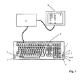
- the FIG. 1 shows a generally designated by the reference numeral 1 sensor unit according to the invention, which is integrated in a computer system consisting of computer 2 and keyboard 3.
- the sensor unit 1 has various measurement modalities that are accessible on the user interface of the keyboard 3. This touches the user of the computer system to perform a measurement with the fingertips.
- light sources 4, 4 'integrated for example in the form of light-emitting diodes, which is capable of Emit light at different wavelengths.
- various light-emitting semiconductor elements in a common sensor housing in FIG. 1 not shown housed.
- the sensor unit 1 comprises one or more photosensors 5.
- the photosensors are arranged in the immediate vicinity of the light source 4 or 4 '.
- the sensors 5 receive the scattered in the tissue at the fingertip of the user light of the light source 4 and 4 '.
- a heat sensor 6 is provided immediately adjacent to the light source 4 or 4 '. This ensures that the determination of the blood flow based on the heat measurement at the same location as the optical measurement.
- a total of four electrodes 7 and 7 'for measuring the bioelectrical impedance are provided on the surface of the sensor unit 1.
- the user of the device touches two electrodes 7 and 7 'simultaneously with one hand. One of the two contact surfaces is used to impress an electrical current at the measuring location, while the other contact surface is used for voltage measurement.
- the two electrodes designated by the reference numeral 7 are also used as ECG electrodes of an ECG unit also integrated into the sensor unit 1.
- the two electrodes are each touched with the fingertips, so that there is a two-point derivation (arm-to-arm measurement).
- the measuring signals recorded by means of the sensor unit 1 integrated in the keyboard 3 are processed by means of the computer 2.
- the physiological parameters thus obtained are then output on a display surface 8 of a monitor 9 connected to the computer 2. Displayed z. Arterial (SaO 2 ), capillary (StO 2 ) and venous (SvO 2 ) oxygen saturation.
- the determined heart rate (HR) and the fat content of the tissue (BF) are also displayed. Finally, a blood glucose value (BG) is displayed.
- HR heart rate
- BF fat content of the tissue
- BG blood glucose value
- the radiation source 4 is a light-emitting diode
- the radiation source 4 ' is a laser, for example a so-called vertical cavity surface-emitting laser (VCSEL).
- VCSEL vertical cavity surface-emitting laser
- the wavelength of the radiation emitted by the two radiation sources 4 and 4 'must be in a range in which the light of oxyhemoglobin and desoxihemoglobin is absorbed to different degrees.
- further radiation sources in the FIG. 1 not shown) whose light wavelength is in a spectral range in which the light absorption of oxyhemoglobin and desoxihemoglobin is substantially the same (so-called isobatic point).
- the light emitted by the light emitting diode or by the laser light can be guided by means of appropriate optical fibers to the appropriate location on the user interface of the keyboard.
- the reference numerals 4 and 4 'in the FIG. 1 the corresponding fiber ends are shown. It is possible to couple the light-emitting diode and the laser to the corresponding fibers in such a way that they radiate into the body tissue to be examined at the desired different opening angle. Accordingly, different volumes of body tissue are examined with both radiation sources. Due to the larger opening angle, the proportion of non-perfused epidermis on the body tissue examined by means of the light-emitting diode is greater than in the case of the laser.
- Both the radiation source 4 and the radiation source 4 ' is detected by means of the sensors 5.
- the sensors 5 need not be arranged directly on the surface of the sensor unit 1. Instead, the light can be supplied via optical fibers to the sensors arranged in the interior of the sensor unit 1.
- the two light sources 4 and 4' can be operated differently modulated in time, the signals detected by the sensors 5 being correspondingly demodulated. Alternatively, it is possible to distinguish the radiation of the two radiation sources 4 and 4 'on the basis of the different wavelength.
- the radiation intensity of the radiation emitted by the radiation sources 4 and 4 ' is weakened with the path length when passing through the body tissue, whereby the connection of the intensity attenuation with the concentration of the absorbing substance (oxygenated hemoglobin) is given by the known Lambert-Beer law.
- the intensity attenuation parameters of interest can be determined separately for the volume regions of the examined body tissue which are respectively detected by the radiation sources 4 and 4 '.
- the intensity attenuation parameters to be assigned to the different radiation sources 4 and 4 ' can be related to one another by means of a suitably program-controlled evaluation unit in order to carry out a differential measurement in this way.
- quotients are calculated from the parameters of the intensity attenuation of the radiation of the two radiation sources 4 and 4 '. Changes in these quotients can then be used to deduce changes in metabolism. If, for example, the blood glucose level rises after ingestion, a correspondingly higher amount of glucose reaches the cells of the body tissue and is metabolized there (after a certain time delay). This oxygen is consumed. The cells receive this oxygen via the blood. In this case, the deoxygenated hemoglobin becomes deoxygenated hemoglobin by the release of oxygen. Accordingly, the ratio of deoxygenated hemoglobin to oxygenated increases.
- the changes in the hemoglobin concentration have a different effect on the respective intensity attenuation.
- the parameter of intensity attenuation changes in hemoglobin concentration can be detected.
- the blood glucose level can also be determined by means of the illustrated differential measurement of the radiation absorption.
- a bioimpedance analysis is performed parallel to the optical measurement, including the in the FIG. 1 shown electrodes 7 and 7 'are provided. The purpose of the bioimpedance measurement is above all the determination of the local perfusion. This can be used as a further parameter in the determination of the oxygen consumption and thus also of the blood glucose level.
- Different opening angles of the radiation can also be generated with only one radiation source 4 by using corresponding optical elements (eg, beam splitters, lenses, etc.).
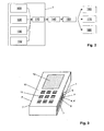
- the FIG. 2 schematically shows the structure of the sensor unit 1 according to the invention as a block diagram.
- the sensor unit 1 comprises an optical measuring unit 100 for the optical measurement of the oxygen concentration in the blood vessel system of the body tissue at the respective measuring location.
- the oximetric and plethysmographic signals detected by means of the optical measuring unit 100 are supplied to an analysis unit 110.
- Another essential component of the device 1 is a heat measuring unit 120 for determining the local heat production.
- the heat measurement unit 120 is a special heat sensor which isolates the body site being examined. This site can thus only absorb or release heat through the bloodstream. Therefore, it is possible to determine the blood circulation and the heat production by the time-resolved measurement of the temperature.
- the examined body site reaches its maximum temperature in a very short time. With less blood flow this takes longer.
- the extrapolation of the measured temperature to the arterial temperature can be concluded, since the temperature at the site of the measurement is determined only by the arterial temperature and by the local heat production.
- the measuring signals detected by means of the heat measuring unit 120 are also fed to the analysis unit 110 for further processing.
- the sensor unit comprises an impedance measuring unit 130, which is used to detect local Gewebeparametem means of bioelectrical impedance measurement.
- the measurement signals of the impedance measurement unit 130 are also processed by the analysis unit 110.
- an ECG unit 132 is provided for detecting an ECG signal.
- the ECG unit 132 is also connected to the analysis unit 110 for processing the ECG signals.
- the heat measuring unit 120 is connected to the heat sensor 6.
- the impedance measurement unit 130 acquires measurement signals via the electrodes 7 or 7 'of the sensor unit 1.
- the analysis unit 110 performs preprocessing of all measurement signals. For this purpose, the signals pass through a bandpass filter to filter out disturbances in the range of the line frequency of 50 or 60 Hz. Furthermore, the signals are subjected to noise suppression. After passing through the analysis unit 110, the processed signals of the optical measuring unit 100, the heat measuring unit 120, the impedance measuring unit 130 and the ECG unit 132 reach an evaluation unit 140.
- the evaluation unit 140 is responsible for determining the parameters which are essential for the diagnosis from the measuring signals to calculate.
- the functions of the evaluation unit 140 are essentially realized by software. Thus, the evaluation unit 140 in the embodiment shown is not part of the actual sensor unit 1.
- the composition of the examined body tissue water content, fat content, etc.
- the arterial oxygen saturation and, based on the tissue parameters previously determined on the basis of the impedance measurement the capillary oxygen saturation is calculated.
- the blood flow and the arterial temperature are determined from the measurement signals of the heat measurement unit 120 and from the plethysmographic data which can be derived from the time-dependent impedance measurement.
- the pulse wave velocity is determined.
- the evaluation unit 140 From the signals of the ECG unit 132 and those of the optical measuring unit 100, the pulse wave velocity is determined. Finally, by means of the evaluation unit 140 from the results of all previously performed calculations, the venous oxygen saturation, and from this further metabolic parameters, in particular the local Oxygen consumption and the glucose concentration calculated at the measuring location. The calculation results are interpreted by means of a diagnostic unit 150.
- the diagnostic unit 150 which is also implemented as software on the computer 2, is used to evaluate the local metabolic parameters calculated by the evaluation unit 140.
- the evaluation unit 140 and the diagnostic unit 150 are connected to display the measurement results with a graphics unit 160, which in turn controls the monitor 9.
- the data obtained can be stored in a memory unit 170, with simultaneous storage of the date and time of the respective measurement.
- an interface unit 180 is provided for connecting the computer 2 to a data network for transmission of the calculated physiological parameters.
- all data and parameters in particular also the data and parameters stored in the memory unit 170, can be transmitted to a PC, not shown, of a treating physician.
- the data can be analyzed in more detail.
- data and parameters recorded with the sensor unit 1 over a relatively long period of time can be examined for changes in order to be able to derive conclusions therefrom with regard to the development of an existing disease.
- FIG. 3 shows a second example of use for the sensor unit 1 according to the invention, namely in a mobile phone 10.
- the usual control buttons 11 can be seen.
- the diagnostic measuring sensors of the sensor unit 1 are integrated flush. This touches the user of the mobile phone 10 to perform a measurement with the fingers.
- On the lateral housing surfaces of the mobile phone 10 a total of four electrodes 7 and 7 'are provided for measuring the bioelectrical impedance.
- the user of the mobile phone 10 touches two electrodes 7 and 7 'simultaneously with one hand. The two electrodes are each touched with the fingertips, so that there is a two-point derivation (arm-to-arm measurement).
- the measuring signals recorded by means of the various sensors integrated into the sensor unit 1 of the mobile telephone 10 are detected by means of the microprocessor (not shown) of the mobile telephone 10 processed.
- the physiological parameters obtained in this way are then output on a display 12 of the mobile telephone 10.
- the user can at any time determine the physiological parameters of interest to him. For this purpose he puts only the fingers, with which he otherwise actuates the keys 11, to the electrodes 7, 7 '.
- the software control of the mobile phone 10 automatically detects the touch and starts the measurement.
- the parameters are then displayed immediately after the processing of the measuring signals by means of the microprocessor of the mobile telephone 10 by means of the display 12.
- the function of the mobile telephone 10 formed by integrating the sensor unit 1 as a medical measuring device is essentially based on the above-described indirect method for the noninvasive determination of the blood glucose value, in which the effect of glucose or the energy conversion of the glucose-initiated physiological reactions in the body is examined , On the corresponding description to explain the in the FIG. 1 shown embodiment is referenced.
- the light sources 4, 4 'and the sensors 5 need not be arranged directly on the housing surface even in the case of the mobile telephone 10. Instead, the light can be guided via optical fibers from or to the housing surface, wherein the actual light sources or sensors are located inside the housing. Several light sources or sensors can be coupled to a single optical fiber.
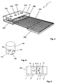
- FIG. 4 illustrates the construction of the diagnostic sensor unit 1 according to the invention.
- the various measuring units of the sensor unit 1 are integrated into a sensor housing 400 with very small external dimensions.
- a flat ECG electrode 7 is arranged, which consists of a thin, electrically conductive film.
- the sensor housing 400 is arranged so that the user the ECG electrode 7 and another electrode (in the FIG. 4 not shown) for ECG lead with different extremities can touch. It makes sense for the ECG electrode to be a thin stainless steel foil.
- an optical measuring unit namely a pulse oximeter
- This comprises two or more optical radiation sources whose radiation can pass through a recess 410 in the ECG electrode 7.
- the pulse oximeter comprises two optical radiation sensors, for example in the form of photodiodes. The light scattered in the body tissue (eg a finger placed on the electrode 7) falls through two recesses 420 and 430 in the electrode 7 onto the radiation sensors.
- the recesses 420 and 430 are arranged at different distances from the recess 410.
- the light from two or more optical radiation sources eg light-emitting diodes
- the photodiodes are individually coupled to an optical fiber or to a suitably designed light-guiding body.
- the optical measuring unit makes it possible to measure the oxygen saturation of the blood circulating in the body tissue under investigation and the volume pulse at the same time.
- a temperature sensor namely a thermistor
- a further recess 440 is provided in the ECG electrode 7.
- the thermistor is disposed in the sensor housing 400 so as to have good thermal contact with the body tissue being examined.
- the thermistor is located between the recess 410 for the optical fiber of the optical radiation sources and the recess 420 for the optical fiber of the first photodiode.
- the sensor unit can easily be supplemented by an impedance measuring unit.
- At least one additional planar electrode (in the FIG. 4 not shown), which then serves as a feed or measuring electrode of the impedance measuring unit. It makes sense the same measuring electrodes are used to detect the bioimpedance signal and the ECG signal.
- the sensor housing 400 with all integrated measuring units is mounted directly on a ribbon cable 450 with a suitable conductor track, so that a simple electrical mounting of the sensor unit 1 by means of the ribbon cable 450 is possible.
- the ribbon cable 450 may have stiffeners 460 at appropriate locations for stabilization purposes.
- FIG. 5 shows the above in terms of the FIG. 4 mentioned light-conducting element 500 with a total of four coupled to the underside of the element 500 LED chips 501, 502, 503 and 504, the light sources of the optical measuring unit of the sensor unit 1 according to the invention form.
- the emitted radiation of all LEDs 501, 502, 503 and 504 is guided to the surface of the sensor housing 400.
- the four LEDs 501, 502, 503 and 504 are bonded side by side on a substrate (not shown), eg a PCB.
- FIG. 6 shows a further embodiment of the invention, wherein at the top of the sensor housing 400 a total of four electrodes 7, 7 ', 7 "and 7'” are arranged, which can be used as feed and measuring electrodes for (local) bioelectrical impedance measurement and for ECG derivation ,
- the electrodes 7, 7 ', 7 "and 7"' are separated from each other by electrically insulating strips 13.
Applications Claiming Priority (2)
| Application Number | Priority Date | Filing Date | Title |
|---|---|---|---|
| DE102007042551 | 2007-09-07 | ||
| PCT/EP2008/007330 WO2009033624A1 (de) | 2007-09-07 | 2008-09-08 | Diagnostische sensoreinheit |
Publications (2)
| Publication Number | Publication Date |
|---|---|
| EP2203113A1 EP2203113A1 (de) | 2010-07-07 |
| EP2203113B1 true EP2203113B1 (de) | 2015-02-25 |
Family
ID=40219244
Family Applications (1)
| Application Number | Title | Priority Date | Filing Date |
|---|---|---|---|
| EP08801909.6A Active EP2203113B1 (de) | 2007-09-07 | 2008-09-08 | Diagnostische sensoreinheit |
Country Status (6)
| Country | Link |
|---|---|
| US (1) | US20100222652A1 (zh) |
| EP (1) | EP2203113B1 (zh) |
| JP (1) | JP5602629B2 (zh) |
| KR (1) | KR101562807B1 (zh) |
| CN (1) | CN101827555B (zh) |
| WO (1) | WO2009033624A1 (zh) |
Families Citing this family (80)
| Publication number | Priority date | Publication date | Assignee | Title |
|---|---|---|---|---|
| EP3827747A1 (en) | 2005-04-28 | 2021-06-02 | Otsuka Pharmaceutical Co., Ltd. | Pharma-informatics system |
| US8912908B2 (en) | 2005-04-28 | 2014-12-16 | Proteus Digital Health, Inc. | Communication system with remote activation |
| US8802183B2 (en) | 2005-04-28 | 2014-08-12 | Proteus Digital Health, Inc. | Communication system with enhanced partial power source and method of manufacturing same |
| US9198608B2 (en) | 2005-04-28 | 2015-12-01 | Proteus Digital Health, Inc. | Communication system incorporated in a container |
| US8730031B2 (en) | 2005-04-28 | 2014-05-20 | Proteus Digital Health, Inc. | Communication system using an implantable device |
| US8836513B2 (en) | 2006-04-28 | 2014-09-16 | Proteus Digital Health, Inc. | Communication system incorporated in an ingestible product |
| JP5714210B2 (ja) | 2005-09-01 | 2015-05-07 | プロテウス デジタル ヘルス, インコーポレイテッド | 移植可能なワイヤ無し通信システム |
| JP2009544338A (ja) | 2006-05-02 | 2009-12-17 | プロテウス バイオメディカル インコーポレイテッド | 患者に合わせてカスタマイズした治療レジメン |
| EP2087589B1 (en) | 2006-10-17 | 2011-11-23 | Proteus Biomedical, Inc. | Low voltage oscillator for medical devices |
| EP2083680B1 (en) | 2006-10-25 | 2016-08-10 | Proteus Digital Health, Inc. | Controlled activation ingestible identifier |
| WO2008061033A2 (en) | 2006-11-10 | 2008-05-22 | Rem Scientific Enterprises, Inc. | Rotating fluid measurement device and method |
| EP2069004A4 (en) | 2006-11-20 | 2014-07-09 | Proteus Digital Health Inc | PERSONAL HEALTH SIGNAL RECEIVERS WITH ACTIVE SIGNAL PROCESSING |
| ES2930588T3 (es) | 2007-02-01 | 2022-12-19 | Otsuka Pharma Co Ltd | Sistemas de marcador de eventos ingeribles |
| KR101528748B1 (ko) | 2007-02-14 | 2015-06-15 | 프로테우스 디지털 헬스, 인코포레이티드 | 고 표면적 전극을 갖는 체내 전원 |
| US9270025B2 (en) | 2007-03-09 | 2016-02-23 | Proteus Digital Health, Inc. | In-body device having deployable antenna |
| EP2124725A1 (en) | 2007-03-09 | 2009-12-02 | Proteus Biomedical, Inc. | In-body device having a multi-directional transmitter |
| US8115618B2 (en) | 2007-05-24 | 2012-02-14 | Proteus Biomedical, Inc. | RFID antenna for in-body device |
| FI2192946T3 (fi) | 2007-09-25 | 2022-11-30 | Elimistön sisäinen laite, jossa on virtuaalinen dipolisignaalinvahvistus | |
| AU2009221781B2 (en) | 2008-03-05 | 2014-12-11 | Otsuka Pharmaceutical Co., Ltd. | Multi-mode communication ingestible event markers and systems, and methods of using the same |
| MY154234A (en) | 2008-07-08 | 2015-05-15 | Proteus Digital Health Inc | Ingestible event marker data framework |
| AU2009281876B2 (en) | 2008-08-13 | 2014-05-22 | Proteus Digital Health, Inc. | Ingestible circuitry |
| KR101192690B1 (ko) | 2008-11-13 | 2012-10-19 | 프로테우스 디지털 헬스, 인코포레이티드 | 섭취 가능한 치료 활성화 시스템, 치료 장치 및 방법 |
| US8055334B2 (en) | 2008-12-11 | 2011-11-08 | Proteus Biomedical, Inc. | Evaluation of gastrointestinal function using portable electroviscerography systems and methods of using the same |
| US9439566B2 (en) | 2008-12-15 | 2016-09-13 | Proteus Digital Health, Inc. | Re-wearable wireless device |
| WO2013012869A1 (en) | 2011-07-21 | 2013-01-24 | Proteus Digital Health, Inc. | Mobile communication device, system, and method |
| US9659423B2 (en) | 2008-12-15 | 2017-05-23 | Proteus Digital Health, Inc. | Personal authentication apparatus system and method |
| TWI424832B (zh) | 2008-12-15 | 2014-02-01 | Proteus Digital Health Inc | 與身體有關的接收器及其方法 |
| JP2012514799A (ja) | 2009-01-06 | 2012-06-28 | プロテウス バイオメディカル インコーポレイテッド | 摂取に関連するバイオフィードバックおよび個別薬物療法の方法およびシステム |
| EP3395333A1 (en) | 2009-01-06 | 2018-10-31 | Proteus Digital Health, Inc. | Pharmaceutical dosages delivery system |
| US20100240972A1 (en) * | 2009-03-20 | 2010-09-23 | Nellcor Puritan Bennett Llc | Slider Spot Check Pulse Oximeter |
| WO2010111403A2 (en) | 2009-03-25 | 2010-09-30 | Proteus Biomedical, Inc. | Probablistic pharmacokinetic and pharmacodynamic modeling |
| CN102458236B (zh) | 2009-04-28 | 2016-01-27 | 普罗秋斯数字健康公司 | 高可靠性的可摄入事件标记器及其使用方法 |
| US9149423B2 (en) | 2009-05-12 | 2015-10-06 | Proteus Digital Health, Inc. | Ingestible event markers comprising an ingestible component |
| US8558563B2 (en) | 2009-08-21 | 2013-10-15 | Proteus Digital Health, Inc. | Apparatus and method for measuring biochemical parameters |
| TWI517050B (zh) | 2009-11-04 | 2016-01-11 | 普羅托斯數位健康公司 | 供應鏈管理之系統 |
| UA109424C2 (uk) | 2009-12-02 | 2015-08-25 | Фармацевтичний продукт, фармацевтична таблетка з електронним маркером і спосіб виготовлення фармацевтичної таблетки | |
| SG182825A1 (en) | 2010-02-01 | 2012-09-27 | Proteus Biomedical Inc | Data gathering system |
| BR112012025650A2 (pt) | 2010-04-07 | 2020-08-18 | Proteus Digital Health, Inc. | dispositivo ingerível miniatura |
| TWI557672B (zh) | 2010-05-19 | 2016-11-11 | 波提亞斯數位康健公司 | 用於從製造商跟蹤藥物直到患者之電腦系統及電腦實施之方法、用於確認將藥物給予患者的設備及方法、患者介面裝置 |
| DE102010032531A1 (de) | 2010-07-28 | 2012-02-02 | Ingo Flore | Portable diagnostische Messvorrichtung |
| JP2014504902A (ja) | 2010-11-22 | 2014-02-27 | プロテウス デジタル ヘルス, インコーポレイテッド | 医薬品を有する摂取可能なデバイス |
| US8761853B2 (en) * | 2011-01-20 | 2014-06-24 | Nitto Denko Corporation | Devices and methods for non-invasive optical physiological measurements |
| US9439599B2 (en) | 2011-03-11 | 2016-09-13 | Proteus Digital Health, Inc. | Wearable personal body associated device with various physical configurations |
| US9756874B2 (en) | 2011-07-11 | 2017-09-12 | Proteus Digital Health, Inc. | Masticable ingestible product and communication system therefor |
| WO2015112603A1 (en) | 2014-01-21 | 2015-07-30 | Proteus Digital Health, Inc. | Masticable ingestible product and communication system therefor |
| US9235683B2 (en) | 2011-11-09 | 2016-01-12 | Proteus Digital Health, Inc. | Apparatus, system, and method for managing adherence to a regimen |
| US20140031646A1 (en) * | 2012-03-29 | 2014-01-30 | Sergey Yakirevich | Blood pressure estimation using a hand-held device |
| US9693697B2 (en) * | 2012-03-29 | 2017-07-04 | Benny Tal | Hand-held device having health monitoring capabilities |
| US9271897B2 (en) | 2012-07-23 | 2016-03-01 | Proteus Digital Health, Inc. | Techniques for manufacturing ingestible event markers comprising an ingestible component |
| US20140051941A1 (en) * | 2012-08-17 | 2014-02-20 | Rare Light, Inc. | Obtaining physiological measurements using a portable device |
| WO2014045774A1 (ja) * | 2012-09-24 | 2014-03-27 | 株式会社村田製作所 | 生体センサ、及び、生体センサの製造方法 |
| SG11201503027SA (en) | 2012-10-18 | 2015-05-28 | Proteus Digital Health Inc | Apparatus, system, and method to adaptively optimize power dissipation and broadcast power in a power source for a communication device |
| WO2014088768A2 (en) * | 2012-12-04 | 2014-06-12 | Brain Tree Analytics Llc | Multi purpose electrode |
| JP2016508529A (ja) | 2013-01-29 | 2016-03-22 | プロテウス デジタル ヘルス, インコーポレイテッド | 高度に膨張可能なポリマーフィルムおよびこれを含む組成物 |
| JP5941240B2 (ja) | 2013-03-15 | 2016-06-29 | プロテウス デジタル ヘルス, インコーポレイテッド | 金属検出器装置、システム、および方法 |
| WO2014151929A1 (en) | 2013-03-15 | 2014-09-25 | Proteus Digital Health, Inc. | Personal authentication apparatus system and method |
| US11744481B2 (en) | 2013-03-15 | 2023-09-05 | Otsuka Pharmaceutical Co., Ltd. | System, apparatus and methods for data collection and assessing outcomes |
| US9796576B2 (en) | 2013-08-30 | 2017-10-24 | Proteus Digital Health, Inc. | Container with electronically controlled interlock |
| EP3047618B1 (en) | 2013-09-20 | 2023-11-08 | Otsuka Pharmaceutical Co., Ltd. | Methods, devices and systems for receiving and decoding a signal in the presence of noise using slices and warping |
| JP2016537924A (ja) | 2013-09-24 | 2016-12-01 | プロテウス デジタル ヘルス, インコーポレイテッド | 事前に正確に把握されていない周波数において受信された電磁信号に関する使用のための方法および装置 |
| US10084880B2 (en) | 2013-11-04 | 2018-09-25 | Proteus Digital Health, Inc. | Social media networking based on physiologic information |
| EP3139825A4 (en) * | 2014-05-05 | 2018-06-27 | Scanadu Incorporated | Portable device with multiple integrated sensors for vital signs scanning |
| WO2015177867A1 (ja) * | 2014-05-20 | 2015-11-26 | パイオニア株式会社 | パルスオキシメータ |
| US10206632B2 (en) * | 2014-07-25 | 2019-02-19 | The Trustees Of Dartmouth College | Systems and methods for cardiovascular-dynamics correlated imaging |
| WO2016085506A1 (en) * | 2014-11-26 | 2016-06-02 | Rem Scientific Enterprises, Inc | Systems and methods for reducing casing noise effects |
| EP3085304A4 (en) * | 2015-01-12 | 2017-09-06 | Chin-Hung Lu | Capacitive sensing head device for measuring frequency of acupuncture point of human body |
| CN104757972B (zh) * | 2015-03-16 | 2024-02-06 | 思澜科技(成都)有限公司 | 一种用于生物阻抗测量的活检夹 |
| CN107530007B (zh) | 2015-04-28 | 2022-06-28 | 京瓷株式会社 | 电子设备及系统 |
| US11051543B2 (en) | 2015-07-21 | 2021-07-06 | Otsuka Pharmaceutical Co. Ltd. | Alginate on adhesive bilayer laminate film |
| EP3337390B9 (en) * | 2015-09-25 | 2021-07-07 | Sanmina Corporation | Health monitoring using a non-invasive, multi-band biosensor |
| DE102016007255A1 (de) | 2016-06-15 | 2017-12-21 | Audi Ag | Kleidungsstück mit integrierter Sensoreinrichtung, Verfahren zum Nutzen des Kleidungsstücks in mehreren Kraftfahrzeugen, System umfassend ein Kraftfahrzeug und ein Kleidungsstück |
| KR102051875B1 (ko) | 2016-07-22 | 2019-12-04 | 프로테우스 디지털 헬스, 인코포레이티드 | 섭취 가능한 이벤트 마커의 전자기 감지 및 검출 |
| EP3531901A4 (en) | 2016-10-26 | 2021-01-27 | Proteus Digital Health, Inc. | CAPSULE PREPARATION PROCESSES WITH INGERABLE EVENT MARKERS |
| KR20190065086A (ko) * | 2017-12-01 | 2019-06-11 | 삼성전자주식회사 | 생체 정보 처리 장치 및 방법 |
| EP3809951A1 (de) * | 2018-06-22 | 2021-04-28 | Flore, Ingo | Messvorrichtung |
| CN112997101A (zh) * | 2018-11-20 | 2021-06-18 | 埃克斯泰克股份有限公司 | 便携式介电谱装置 |
| PL428519A1 (pl) * | 2019-01-08 | 2020-07-13 | Politechnika Śląska | Urządzenie peryferyjne wspierające badania psychologiczne |
| EP3705041A1 (de) * | 2019-03-05 | 2020-09-09 | Luciole Medical AG | Sensoranordnung |
| CN111818447B (zh) * | 2020-06-02 | 2023-05-23 | 深圳全景空间工业有限公司 | 一种室内人居环境的传感器网络 |
| CN111854753B (zh) * | 2020-06-02 | 2023-05-23 | 深圳全景空间工业有限公司 | 一种室内空间的建模方法 |
Citations (1)
| Publication number | Priority date | Publication date | Assignee | Title |
|---|---|---|---|---|
| WO2008061788A1 (de) * | 2006-11-23 | 2008-05-29 | Flore, Ingo | Medizinische messvorrichtung |
Family Cites Families (24)
| Publication number | Priority date | Publication date | Assignee | Title |
|---|---|---|---|---|
| US5237178A (en) * | 1990-06-27 | 1993-08-17 | Rosenthal Robert D | Non-invasive near-infrared quantitative measurement instrument |
| DE4342105A1 (de) * | 1993-12-12 | 1995-06-14 | Cho Ok Kyung | Verfahren und Vorrichtung zur noninvasiven Bestimmung der Konzentration der Glucose in Teilen des menschlichen Körpers, inbesondere im menschlichen Blut, unter Durchführung höchstgenauer Temperaturmessungen des menschlichen Körpers |
| DE4423663A1 (de) * | 1994-07-06 | 1996-01-11 | Med Science Gmbh | Verfahren und Vorrichtung zur Erfassung von Wärmewechselwirkungen zwischen dem menschlichen Körper und der erfindungsgemäßen Vorrichtung und deren Korrelation mit der Glucosekonzentration im menschlichen Blut |
| JPH09122083A (ja) * | 1995-10-30 | 1997-05-13 | Noboru Akasaka | 常時装着可能な患者モニタ装置 |
| US6041247A (en) * | 1995-11-29 | 2000-03-21 | Instrumentarium Corp | Non-invasive optical measuring sensor and measuring method |
| US6790178B1 (en) * | 1999-09-24 | 2004-09-14 | Healthetech, Inc. | Physiological monitor and associated computation, display and communication unit |
| JP4092769B2 (ja) * | 1998-04-21 | 2008-05-28 | 松下電器産業株式会社 | 生体モニタ装置 |
| JP2000083933A (ja) * | 1998-07-17 | 2000-03-28 | Nippon Koden Corp | 生体組織中吸光物質濃度測定装置 |
| US6331162B1 (en) * | 1999-02-01 | 2001-12-18 | Gary F. Mitchell | Pulse wave velocity measuring device |
| US6616613B1 (en) * | 2000-04-27 | 2003-09-09 | Vitalsines International, Inc. | Physiological signal monitoring system |
| JP3475156B2 (ja) * | 2000-08-01 | 2003-12-08 | 三洋電機株式会社 | バイタルセンサ |
| DE10136355A1 (de) * | 2001-07-26 | 2003-02-13 | Niels Rahe-Meyer | Vorrichtung zur Untersuchung und Überwachung von Vitalparamentern des Körpers |
| GB2381530A (en) * | 2001-11-01 | 2003-05-07 | Oxonica Ltd | Water-soluble particles of luminescent materials and their use in Biotagging |
| JP2004024551A (ja) * | 2002-06-26 | 2004-01-29 | Renesas Technology Corp | センサシステム用半導体装置 |
| US6879850B2 (en) * | 2002-08-16 | 2005-04-12 | Optical Sensors Incorporated | Pulse oximeter with motion detection |
| CA2501732C (en) * | 2002-10-09 | 2013-07-30 | Bodymedia, Inc. | Method and apparatus for auto journaling of continuous or discrete body states utilizing physiological and/or contextual parameters |
| US20050148882A1 (en) * | 2004-01-06 | 2005-07-07 | Triage Wireless, Incc. | Vital signs monitor used for conditioning a patient's response |
| US7305262B2 (en) * | 2003-12-11 | 2007-12-04 | Ge Medical Systems Information Technologies, Inc. | Apparatus and method for acquiring oximetry and electrocardiogram signals |
| WO2005077260A1 (en) * | 2004-02-12 | 2005-08-25 | Biopeak Corporation | Non-invasive method and apparatus for determining a physiological parameter |
| US20060009697A1 (en) * | 2004-04-07 | 2006-01-12 | Triage Wireless, Inc. | Wireless, internet-based system for measuring vital signs from a plurality of patients in a hospital or medical clinic |
| DE102005013429A1 (de) * | 2005-03-21 | 2006-09-28 | Flore, Ingo, Dr. | Mobiles Diagnosegerät |
| EP1931239B1 (de) * | 2005-08-09 | 2012-08-08 | Flore, Ingo | Medizinische messvorrichtung |
| JP2007105329A (ja) * | 2005-10-14 | 2007-04-26 | Hitachi Ltd | 血糖値測定装置及び代謝量測定装置 |
| US7486977B2 (en) * | 2005-10-27 | 2009-02-03 | Smiths Medical Pm, Inc. | Single use pulse oximeter |
-
2008
- 2008-09-08 KR KR1020107006263A patent/KR101562807B1/ko active IP Right Grant
- 2008-09-08 EP EP08801909.6A patent/EP2203113B1/de active Active
- 2008-09-08 CN CN2008801121472A patent/CN101827555B/zh active Active
- 2008-09-08 US US12/733,549 patent/US20100222652A1/en not_active Abandoned
- 2008-09-08 WO PCT/EP2008/007330 patent/WO2009033624A1/de active Application Filing
- 2008-09-08 JP JP2010523329A patent/JP5602629B2/ja active Active
Patent Citations (1)
| Publication number | Priority date | Publication date | Assignee | Title |
|---|---|---|---|---|
| WO2008061788A1 (de) * | 2006-11-23 | 2008-05-29 | Flore, Ingo | Medizinische messvorrichtung |
Also Published As
| Publication number | Publication date |
|---|---|
| US20100222652A1 (en) | 2010-09-02 |
| JP2010537751A (ja) | 2010-12-09 |
| CN101827555A (zh) | 2010-09-08 |
| KR20100068400A (ko) | 2010-06-23 |
| EP2203113A1 (de) | 2010-07-07 |
| KR101562807B1 (ko) | 2015-11-02 |
| WO2009033624A1 (de) | 2009-03-19 |
| CN101827555B (zh) | 2012-11-21 |
| JP5602629B2 (ja) | 2014-10-08 |
Similar Documents
| Publication | Publication Date | Title |
|---|---|---|
| EP2203113B1 (de) | Diagnostische sensoreinheit | |
| EP2096989B1 (de) | Medizinische messvorrichtung | |
| EP2203114B1 (de) | Medizinische messvorrichtung zur bioelektrischen impedanzmessung | |
| EP2403398B1 (de) | Diagnostische messvorrichtung | |
| EP1931239B1 (de) | Medizinische messvorrichtung | |
| EP2096984B1 (de) | Medizinische messvorrichtung | |
| DE102006055691A1 (de) | Medizinische Messvorrichtung | |
| DE69727243T2 (de) | Sensor zur an die bewegung angepasste nicht-invasiven optischen blutanalyse | |
| Ferrari et al. | Near infrared brain and muscle oximetry: from the discovery to current applications | |
| DE602004010939T2 (de) | Methode und Vorrichtung zur menschlichen Stressevaluierung durch Photoplethysmographie | |
| DE10392677B4 (de) | Vorrichtung und Verfahren zum Monitoring des autonomen Nervensystems | |
| EP1860999B1 (de) | Mobiles diagnosegerät | |
| DE102005057757A1 (de) | Integrale Vorrichtung zur Bestimmung physiologischer Signale | |
| DE60032455T2 (de) | Verfahren und vorrichtung zur quantifizierung der narkosetiefe auf optischem wege | |
| DE112013005657T5 (de) | Oxymetriesensoranordnung und Vorgehensweise zum Abtasten einer Blutsauerstoffkonzentration | |
| DE102016006196A1 (de) | Innovatives verfahren und multisensor-plattform zum nichtinvasiven monitoring von physiologischen parameter und blutinhaltstoffe sowie frühdiagnose der pathologischen änderungen und gesundheits-management und ihre anwendung mit smartphone | |
| DE102006051561A1 (de) | Anzeigemittel für Vitalparameter | |
| EP2609854B1 (de) | Bewegungskorreliertes Verfahren und opto-elektronische Vorrichtung zur nichtinvasiven Bestimmung der dermalvenösen Sauerstoffversorgung peripherer Beingebiete | |
| DE102015015113A1 (de) | Verfahren und multisensor zum nichtinvasiven monitoring von physiologischen parameter und blutinhaltstoffe sowie frühdiagnose der pathologischen änderungen mittels fuzzy logik datafusion für decision making und consulting bei internet of things | |
| DE102006026126A1 (de) | Verfahren und Multisensor zur nichtinvasiven Überwachung der fraktionellen Sauerstoffsättigung und Detektion pathologischer Veränderungen im Herzkreislaufsystem | |
| Shi | Photoplethysmography in noninvasive cardiovascular assessment | |
| DE102006045192A1 (de) | Messvorrichtung für die fetale Transmissions-Pulsoximetrie |
Legal Events
| Date | Code | Title | Description |
|---|---|---|---|
| PUAI | Public reference made under article 153(3) epc to a published international application that has entered the european phase |
Free format text: ORIGINAL CODE: 0009012 |
|
| 17P | Request for examination filed |
Effective date: 20100407 |
|
| AK | Designated contracting states |
Kind code of ref document: A1 Designated state(s): AT BE BG CH CY CZ DE DK EE ES FI FR GB GR HR HU IE IS IT LI LT LU LV MC MT NL NO PL PT RO SE SI SK TR |
|
| AX | Request for extension of the european patent |
Extension state: AL BA MK RS |
|
| DAX | Request for extension of the european patent (deleted) | ||
| 17Q | First examination report despatched |
Effective date: 20110113 |
|
| RIC1 | Information provided on ipc code assigned before grant |
Ipc: A61B 5/022 20060101ALI20140814BHEP Ipc: A61B 5/00 20060101AFI20140814BHEP Ipc: A61B 5/01 20060101ALI20140814BHEP Ipc: A61B 5/0402 20060101ALI20140814BHEP Ipc: A61B 5/1455 20060101ALI20140814BHEP Ipc: A61B 5/024 20060101ALI20140814BHEP Ipc: A61B 5/053 20060101ALI20140814BHEP Ipc: A61B 5/02 20060101ALI20140814BHEP |
|
| GRAP | Despatch of communication of intention to grant a patent |
Free format text: ORIGINAL CODE: EPIDOSNIGR1 |
|
| INTG | Intention to grant announced |
Effective date: 20140929 |
|
| GRAS | Grant fee paid |
Free format text: ORIGINAL CODE: EPIDOSNIGR3 |
|
| GRAA | (expected) grant |
Free format text: ORIGINAL CODE: 0009210 |
|
| AK | Designated contracting states |
Kind code of ref document: B1 Designated state(s): AT BE BG CH CY CZ DE DK EE ES FI FR GB GR HR HU IE IS IT LI LT LU LV MC MT NL NO PL PT RO SE SI SK TR |
|
| REG | Reference to a national code |
Ref country code: GB Ref legal event code: FG4D Free format text: NOT ENGLISH |
|
| REG | Reference to a national code |
Ref country code: CH Ref legal event code: EP |
|
| REG | Reference to a national code |
Ref country code: IE Ref legal event code: FG4D Free format text: LANGUAGE OF EP DOCUMENT: GERMAN |
|
| REG | Reference to a national code |
Ref country code: DE Ref legal event code: R096 Ref document number: 502008012705 Country of ref document: DE Effective date: 20150409 |
|
| REG | Reference to a national code |
Ref country code: AT Ref legal event code: REF Ref document number: 711200 Country of ref document: AT Kind code of ref document: T Effective date: 20150415 |
|
| REG | Reference to a national code |
Ref country code: NL Ref legal event code: VDEP Effective date: 20150225 |
|
| REG | Reference to a national code |
Ref country code: LT Ref legal event code: MG4D |
|
| PG25 | Lapsed in a contracting state [announced via postgrant information from national office to epo] |
Ref country code: NO Free format text: LAPSE BECAUSE OF FAILURE TO SUBMIT A TRANSLATION OF THE DESCRIPTION OR TO PAY THE FEE WITHIN THE PRESCRIBED TIME-LIMIT Effective date: 20150525 Ref country code: LT Free format text: LAPSE BECAUSE OF FAILURE TO SUBMIT A TRANSLATION OF THE DESCRIPTION OR TO PAY THE FEE WITHIN THE PRESCRIBED TIME-LIMIT Effective date: 20150225 Ref country code: SE Free format text: LAPSE BECAUSE OF FAILURE TO SUBMIT A TRANSLATION OF THE DESCRIPTION OR TO PAY THE FEE WITHIN THE PRESCRIBED TIME-LIMIT Effective date: 20150225 Ref country code: FI Free format text: LAPSE BECAUSE OF FAILURE TO SUBMIT A TRANSLATION OF THE DESCRIPTION OR TO PAY THE FEE WITHIN THE PRESCRIBED TIME-LIMIT Effective date: 20150225 Ref country code: HR Free format text: LAPSE BECAUSE OF FAILURE TO SUBMIT A TRANSLATION OF THE DESCRIPTION OR TO PAY THE FEE WITHIN THE PRESCRIBED TIME-LIMIT Effective date: 20150225 Ref country code: ES Free format text: LAPSE BECAUSE OF FAILURE TO SUBMIT A TRANSLATION OF THE DESCRIPTION OR TO PAY THE FEE WITHIN THE PRESCRIBED TIME-LIMIT Effective date: 20150225 |
|
| PG25 | Lapsed in a contracting state [announced via postgrant information from national office to epo] |
Ref country code: LV Free format text: LAPSE BECAUSE OF FAILURE TO SUBMIT A TRANSLATION OF THE DESCRIPTION OR TO PAY THE FEE WITHIN THE PRESCRIBED TIME-LIMIT Effective date: 20150225 Ref country code: GR Free format text: LAPSE BECAUSE OF FAILURE TO SUBMIT A TRANSLATION OF THE DESCRIPTION OR TO PAY THE FEE WITHIN THE PRESCRIBED TIME-LIMIT Effective date: 20150526 Ref country code: IS Free format text: LAPSE BECAUSE OF FAILURE TO SUBMIT A TRANSLATION OF THE DESCRIPTION OR TO PAY THE FEE WITHIN THE PRESCRIBED TIME-LIMIT Effective date: 20150625 |
|
| REG | Reference to a national code |
Ref country code: FR Ref legal event code: PLFP Year of fee payment: 8 |
|
| PG25 | Lapsed in a contracting state [announced via postgrant information from national office to epo] |
Ref country code: NL Free format text: LAPSE BECAUSE OF FAILURE TO SUBMIT A TRANSLATION OF THE DESCRIPTION OR TO PAY THE FEE WITHIN THE PRESCRIBED TIME-LIMIT Effective date: 20150225 |
|
| PG25 | Lapsed in a contracting state [announced via postgrant information from national office to epo] |
Ref country code: EE Free format text: LAPSE BECAUSE OF FAILURE TO SUBMIT A TRANSLATION OF THE DESCRIPTION OR TO PAY THE FEE WITHIN THE PRESCRIBED TIME-LIMIT Effective date: 20150225 Ref country code: RO Free format text: LAPSE BECAUSE OF FAILURE TO SUBMIT A TRANSLATION OF THE DESCRIPTION OR TO PAY THE FEE WITHIN THE PRESCRIBED TIME-LIMIT Effective date: 20150225 Ref country code: SK Free format text: LAPSE BECAUSE OF FAILURE TO SUBMIT A TRANSLATION OF THE DESCRIPTION OR TO PAY THE FEE WITHIN THE PRESCRIBED TIME-LIMIT Effective date: 20150225 Ref country code: DK Free format text: LAPSE BECAUSE OF FAILURE TO SUBMIT A TRANSLATION OF THE DESCRIPTION OR TO PAY THE FEE WITHIN THE PRESCRIBED TIME-LIMIT Effective date: 20150225 Ref country code: CZ Free format text: LAPSE BECAUSE OF FAILURE TO SUBMIT A TRANSLATION OF THE DESCRIPTION OR TO PAY THE FEE WITHIN THE PRESCRIBED TIME-LIMIT Effective date: 20150225 |
|
| REG | Reference to a national code |
Ref country code: DE Ref legal event code: R097 Ref document number: 502008012705 Country of ref document: DE |
|
| PG25 | Lapsed in a contracting state [announced via postgrant information from national office to epo] |
Ref country code: PL Free format text: LAPSE BECAUSE OF FAILURE TO SUBMIT A TRANSLATION OF THE DESCRIPTION OR TO PAY THE FEE WITHIN THE PRESCRIBED TIME-LIMIT Effective date: 20150225 |
|
| PG25 | Lapsed in a contracting state [announced via postgrant information from national office to epo] |
Ref country code: IT Free format text: LAPSE BECAUSE OF FAILURE TO SUBMIT A TRANSLATION OF THE DESCRIPTION OR TO PAY THE FEE WITHIN THE PRESCRIBED TIME-LIMIT Effective date: 20150225 |
|
| PLBE | No opposition filed within time limit |
Free format text: ORIGINAL CODE: 0009261 |
|
| STAA | Information on the status of an ep patent application or granted ep patent |
Free format text: STATUS: NO OPPOSITION FILED WITHIN TIME LIMIT |
|
| 26N | No opposition filed |
Effective date: 20151126 |
|
| PG25 | Lapsed in a contracting state [announced via postgrant information from national office to epo] |
Ref country code: SI Free format text: LAPSE BECAUSE OF FAILURE TO SUBMIT A TRANSLATION OF THE DESCRIPTION OR TO PAY THE FEE WITHIN THE PRESCRIBED TIME-LIMIT Effective date: 20150225 |
|
| PG25 | Lapsed in a contracting state [announced via postgrant information from national office to epo] |
Ref country code: LU Free format text: LAPSE BECAUSE OF FAILURE TO SUBMIT A TRANSLATION OF THE DESCRIPTION OR TO PAY THE FEE WITHIN THE PRESCRIBED TIME-LIMIT Effective date: 20150908 Ref country code: MC Free format text: LAPSE BECAUSE OF FAILURE TO SUBMIT A TRANSLATION OF THE DESCRIPTION OR TO PAY THE FEE WITHIN THE PRESCRIBED TIME-LIMIT Effective date: 20150225 |
|
| REG | Reference to a national code |
Ref country code: CH Ref legal event code: PL |
|
| REG | Reference to a national code |
Ref country code: IE Ref legal event code: MM4A |
|
| PG25 | Lapsed in a contracting state [announced via postgrant information from national office to epo] |
Ref country code: CH Free format text: LAPSE BECAUSE OF NON-PAYMENT OF DUE FEES Effective date: 20150930 Ref country code: LI Free format text: LAPSE BECAUSE OF NON-PAYMENT OF DUE FEES Effective date: 20150930 Ref country code: IE Free format text: LAPSE BECAUSE OF NON-PAYMENT OF DUE FEES Effective date: 20150908 |
|
| REG | Reference to a national code |
Ref country code: FR Ref legal event code: PLFP Year of fee payment: 9 |
|
| REG | Reference to a national code |
Ref country code: AT Ref legal event code: MM01 Ref document number: 711200 Country of ref document: AT Kind code of ref document: T Effective date: 20150908 |
|
| PG25 | Lapsed in a contracting state [announced via postgrant information from national office to epo] |
Ref country code: AT Free format text: LAPSE BECAUSE OF NON-PAYMENT OF DUE FEES Effective date: 20150908 |
|
| PG25 | Lapsed in a contracting state [announced via postgrant information from national office to epo] |
Ref country code: MT Free format text: LAPSE BECAUSE OF FAILURE TO SUBMIT A TRANSLATION OF THE DESCRIPTION OR TO PAY THE FEE WITHIN THE PRESCRIBED TIME-LIMIT Effective date: 20150225 |
|
| PG25 | Lapsed in a contracting state [announced via postgrant information from national office to epo] |
Ref country code: HU Free format text: LAPSE BECAUSE OF FAILURE TO SUBMIT A TRANSLATION OF THE DESCRIPTION OR TO PAY THE FEE WITHIN THE PRESCRIBED TIME-LIMIT; INVALID AB INITIO Effective date: 20080908 Ref country code: BG Free format text: LAPSE BECAUSE OF FAILURE TO SUBMIT A TRANSLATION OF THE DESCRIPTION OR TO PAY THE FEE WITHIN THE PRESCRIBED TIME-LIMIT Effective date: 20150225 |
|
| PG25 | Lapsed in a contracting state [announced via postgrant information from national office to epo] |
Ref country code: CY Free format text: LAPSE BECAUSE OF FAILURE TO SUBMIT A TRANSLATION OF THE DESCRIPTION OR TO PAY THE FEE WITHIN THE PRESCRIBED TIME-LIMIT Effective date: 20150225 |
|
| PG25 | Lapsed in a contracting state [announced via postgrant information from national office to epo] |
Ref country code: BE Free format text: LAPSE BECAUSE OF NON-PAYMENT OF DUE FEES Effective date: 20150930 |
|
| PG25 | Lapsed in a contracting state [announced via postgrant information from national office to epo] |
Ref country code: TR Free format text: LAPSE BECAUSE OF FAILURE TO SUBMIT A TRANSLATION OF THE DESCRIPTION OR TO PAY THE FEE WITHIN THE PRESCRIBED TIME-LIMIT Effective date: 20150225 |
|
| REG | Reference to a national code |
Ref country code: FR Ref legal event code: PLFP Year of fee payment: 10 |
|
| PG25 | Lapsed in a contracting state [announced via postgrant information from national office to epo] |
Ref country code: PT Free format text: LAPSE BECAUSE OF FAILURE TO SUBMIT A TRANSLATION OF THE DESCRIPTION OR TO PAY THE FEE WITHIN THE PRESCRIBED TIME-LIMIT Effective date: 20150225 |
|
| REG | Reference to a national code |
Ref country code: FR Ref legal event code: PLFP Year of fee payment: 11 |
|
| P01 | Opt-out of the competence of the unified patent court (upc) registered |
Effective date: 20230428 |
|
| PGFP | Annual fee paid to national office [announced via postgrant information from national office to epo] |
Ref country code: GB Payment date: 20230920 Year of fee payment: 16 |
|
| PGFP | Annual fee paid to national office [announced via postgrant information from national office to epo] |
Ref country code: FR Payment date: 20230928 Year of fee payment: 16 Ref country code: DE Payment date: 20230920 Year of fee payment: 16 |