EP2201643B1 - Procédé de production d'un système d'antenne de véhicule - Google Patents
Procédé de production d'un système d'antenne de véhicule Download PDFInfo
- Publication number
- EP2201643B1 EP2201643B1 EP08839690A EP08839690A EP2201643B1 EP 2201643 B1 EP2201643 B1 EP 2201643B1 EP 08839690 A EP08839690 A EP 08839690A EP 08839690 A EP08839690 A EP 08839690A EP 2201643 B1 EP2201643 B1 EP 2201643B1
- Authority
- EP
- European Patent Office
- Prior art keywords
- carrier film
- antenna device
- tab
- vehicle
- vehicle antenna
- Prior art date
- Legal status (The legal status is an assumption and is not a legal conclusion. Google has not performed a legal analysis and makes no representation as to the accuracy of the status listed.)
- Active
Links
Images


Classifications
-
- B—PERFORMING OPERATIONS; TRANSPORTING
- B60—VEHICLES IN GENERAL
- B60R—VEHICLES, VEHICLE FITTINGS, OR VEHICLE PARTS, NOT OTHERWISE PROVIDED FOR
- B60R1/00—Optical viewing arrangements; Real-time viewing arrangements for drivers or passengers using optical image capturing systems, e.g. cameras or video systems specially adapted for use in or on vehicles
- B60R1/12—Mirror assemblies combined with other articles, e.g. clocks
-
- H—ELECTRICITY
- H01—ELECTRIC ELEMENTS
- H01Q—ANTENNAS, i.e. RADIO AERIALS
- H01Q1/00—Details of, or arrangements associated with, antennas
- H01Q1/27—Adaptation for use in or on movable bodies
- H01Q1/32—Adaptation for use in or on road or rail vehicles
- H01Q1/325—Adaptation for use in or on road or rail vehicles characterised by the location of the antenna on the vehicle
- H01Q1/3266—Adaptation for use in or on road or rail vehicles characterised by the location of the antenna on the vehicle using the mirror of the vehicle
-
- H—ELECTRICITY
- H01—ELECTRIC ELEMENTS
- H01Q—ANTENNAS, i.e. RADIO AERIALS
- H01Q1/00—Details of, or arrangements associated with, antennas
- H01Q1/36—Structural form of radiating elements, e.g. cone, spiral, umbrella; Particular materials used therewith
- H01Q1/38—Structural form of radiating elements, e.g. cone, spiral, umbrella; Particular materials used therewith formed by a conductive layer on an insulating support
-
- B—PERFORMING OPERATIONS; TRANSPORTING
- B60—VEHICLES IN GENERAL
- B60R—VEHICLES, VEHICLE FITTINGS, OR VEHICLE PARTS, NOT OTHERWISE PROVIDED FOR
- B60R1/00—Optical viewing arrangements; Real-time viewing arrangements for drivers or passengers using optical image capturing systems, e.g. cameras or video systems specially adapted for use in or on vehicles
- B60R1/12—Mirror assemblies combined with other articles, e.g. clocks
- B60R2001/1261—Mirror assemblies combined with other articles, e.g. clocks with antennae
-
- H—ELECTRICITY
- H01—ELECTRIC ELEMENTS
- H01R—ELECTRICALLY-CONDUCTIVE CONNECTIONS; STRUCTURAL ASSOCIATIONS OF A PLURALITY OF MUTUALLY-INSULATED ELECTRICAL CONNECTING ELEMENTS; COUPLING DEVICES; CURRENT COLLECTORS
- H01R2201/00—Connectors or connections adapted for particular applications
- H01R2201/02—Connectors or connections adapted for particular applications for antennas
-
- H—ELECTRICITY
- H01—ELECTRIC ELEMENTS
- H01R—ELECTRICALLY-CONDUCTIVE CONNECTIONS; STRUCTURAL ASSOCIATIONS OF A PLURALITY OF MUTUALLY-INSULATED ELECTRICAL CONNECTING ELEMENTS; COUPLING DEVICES; CURRENT COLLECTORS
- H01R2201/00—Connectors or connections adapted for particular applications
- H01R2201/26—Connectors or connections adapted for particular applications for vehicles
-
- Y—GENERAL TAGGING OF NEW TECHNOLOGICAL DEVELOPMENTS; GENERAL TAGGING OF CROSS-SECTIONAL TECHNOLOGIES SPANNING OVER SEVERAL SECTIONS OF THE IPC; TECHNICAL SUBJECTS COVERED BY FORMER USPC CROSS-REFERENCE ART COLLECTIONS [XRACs] AND DIGESTS
- Y10—TECHNICAL SUBJECTS COVERED BY FORMER USPC
- Y10T—TECHNICAL SUBJECTS COVERED BY FORMER US CLASSIFICATION
- Y10T29/00—Metal working
- Y10T29/49—Method of mechanical manufacture
- Y10T29/49002—Electrical device making
- Y10T29/49016—Antenna or wave energy "plumbing" making
Definitions
- the invention relates to a method for producing a vehicle antenna device and a vehicle antenna device produced thereon according to the features of the respective preamble of the independent claims.
- Methods are known for producing vehicle antenna directions which have a carrier foil of an electrically nonconductive material, wherein antenna structures in the desired shape and extent of an electrically conductive material are applied to the carrier foil.
- one or more supply lines are applied to the carrier film, via which the antenna structure or a plurality of antenna structures are connected to an electronic device, in particular an antenna amplifier.
- this has the disadvantage that in addition carrier film and the leads thereon must be made in order to connect the vehicle antenna device with the electronic device can.
- a generic method is from the DE 10 2005 009 443 A1 known.
- the invention is therefore based on the object to provide a method for producing a vehicle antenna device and a vehicle antenna device produced thereafter, which is further improved in terms of their production, their storage and also with regard to the assembly.
- the method of manufacturing the vehicle antenna device includes, among other things, attaching and electrically contacting a connector or an electronic device to a base of the antenna structure.
- a connector or an electronic device preferably an antenna amplifier
- This has the advantage that the connector or the electronic device, preferably an antenna amplifier, is fastened and electrically contacted directly at the location with the base point of the antenna structure on which the received high-frequency signals are transmitted via the connector or directly from the antenna electronic device to be processed further.
- This can be omitted in an advantageous manner leads, which would also allow irradiation of interfering signals.
- the vehicle antenna device according to the invention builds much more compact.
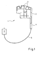
- FIG. 1 shows, as far as shown in detail, a vehicle antenna device 1, in which one or more antenna structures 3 on a carrier film 2 made of an electrically non-conductive material, in particular a flexible plastic film are applied.
- the application of the antenna structures 3 is effected by printing, for example screen printing, an electrically conductive paste, preferably a silver polymer paste, on the sheet-like carrier film 2.
- Other materials for the antenna structures 3 are conceivable.
- From the carrier film 2 is a tab, wherein on the tab, a connector 4 at the end of the antenna structure 3, which forms the base, is arranged. At the same time, a contact partner of the connector 4, not shown here, is mechanically and electrically connected to the base of the antenna structure 3.
- Vehicle antenna device 1 represents the simplest embodiment of the vehicle antenna device 1 according to the invention, wherein the carrier film 2 is already provided with recesses in the outer contour and recesses, in particular round openings, with which the carrier film 2 is fixed in position and fixed at the desired installation location.
- the contouring of the carrier film 2 can be done for example by cutting or punching a larger area of a carrier film.
- the carrier foil 2 is provided with at least one separating cut 7 before or after the plug connector 4 or the electronic device 6 has been arranged, whereby the carrier foil 2 is divided into at least two mutually independent movable but mutually connected partial surfaces.
- This separation cut can also be done by a cutting or punching process. Other methods for achieving the described effect are also conceivable.
- the separating cut 7 preferably takes place from one side edge of the carrier film 2 in the direction of the inner region of the carrier film 2, so that at least two or more arise independently movable, but still interconnected faces.
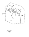
- the carrier foil 2 processed in this way can be mounted at the desired installation location, it is provided with at least one attachment point 8, preferably a plurality of attachment points 8. According to the invention, it is provided that the at least one attachment point 8 is punched out, wherein the region of the carrier foil 2 punched out to form the attachment point 8 remains there and is folded away at least during the attachment process.
- the carrier film 2 is provided with at least one further recess 11 in the carrier film 2, wherein this is done, for example, by means of its punching operation. It remains within the recess 11th a punched-out region of the carrier film 2 as a fastening tab 10, with which the carrier film 2 is attached to the desired installation location.
- the fastening tab 10 is approximately T-shaped, wherein portions of the carrier film 2 are punched out and removed. It is conceivable that the remaining fastening tab 10 is folded in at least once again for the purpose of stiffening.
- the fastening tab 11 in particular also a plurality of fastening tabs 11 provided at the required locations, has the advantage that the carrier foil 2 can be fastened by hanging and preferably also by latching or bracing with a vehicle component. This advantage is given in particular if, for example, two opposite fastening straps 11 comprise the vehicle component under prestressing.
- the vehicle antenna device 1 In addition or as an alternative to a non-positive connection of the fastening straps 11 with the vehicle component, it is conceivable for the vehicle antenna device 1 to be connected in a form-fitting manner to the vehicle component via the fastening straps 11, for example by an adhesive process.
- the sheet carrier film 2 with at least one protruding tab 12, preferably a plurality of protruding tabs 12, is provided before or after the attachment of the connector 4 or the electronic device 6, the sheet carrier film 2 with at least one protruding tab 12, preferably a plurality of protruding tabs 12, is provided.
- the still flat carrier film 2 does not have the shape that corresponds to the desired three-dimensional installation location.
- an incision 13 is introduced into the carrier film 2, in which the at least one tab 12 is inserted after the carrier film 2 symmetrically or asymmetrically deformed to an axis of symmetry 14 of the carrier film 2 ie bent or was angled.
- This deformation takes place, for example, with a small or large scale radius along a fold line 15, wherein it is also conceivable that the deformation takes place at a certain angle, preferably at a right angle.
- This deformation is in FIG. 5 wherein it can be seen that the protruding tabs 12 have been folded over relative to the remaining portion of the carrier film 2, wherein in this embodiment, portions of the carrier film 2 have been folded, in which the associated incisions 13 are located.
- the protruding tabs 12 can be performed with their front free end through the incisions 13, wherein in a particularly advantageous manner, the free front portion of the protruding tab 12 is hook-shaped, so that the outwardly projecting hooks, preferably a plurality of hooks of the protruding tab 12, the Carrier sheet 2 after passing through the tab 12 engages behind the recess 13 and thus this front portion of the protruding tab 12 is fixed.
- the front end is provided with a chamfer.
- an initially roughly planar carrier foil 2 can be used to produce an approximately box-shaped antenna device in this case, the inner or outer contours of this now three-dimensionally shaped carrier foil 2 preferably corresponding to the desired installation location.
- the existing fold lines 15 and the folding operations to be carried out virtually any complex three-dimensional shapes of the previously flat carrier foil 2 can be achieved.
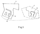
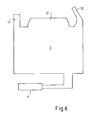
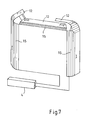
- FIGS. 6 to 8 A slightly more complex design of the carrier film 2 is based on FIGS. 6 to 8 shown. Again, the carrier film 2 is again provided with a plurality of protruding tabs 12, wherein portions of the carrier film 2 along folding lines 15 in this case are not folded, but bent so that along the fold lines 15 no sharp, but a rounded deformation region is formed.
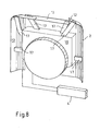
- the carrier film 2 was deformed three-dimensionally ( FIG. 7 ), the attachment of the thus three-dimensionally deformed carrier film 2 to a vehicle component 16 (FIG. FIG. 8 ).
- the bent partial surfaces of the carrier foil 2 at least partially, in particular completely at its side edges comprise the vehicle component 16, so that the carrier foil 2 is fixed to the vehicle component 16 by such a form fit.
- the vehicle component 16 has outwardly facing struts 17, wherein these struts 17 are connected in their end region with the deformed partial surfaces of the carrier film 2. This can be done by traction and / or by positive locking.
- the struts 17 are independent components, with which the carrier film 2 is connected to the vehicle component 16.
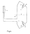
- FIG. 9 a particularly preferred embodiment of the vehicle antenna device 1 is shown, which has been produced by the method according to the invention.
- the three-dimensionally prepared carrier film 2 is brought into a shape which corresponds to the installation location desired here, namely within a housing of an exterior mirror 18 of a vehicle.
- the inner contours of the housing of the exterior mirror 18 are extremely complex (curved) and there is little space available because not only the vehicle antenna device 1 is to be accommodated within the housing of the exterior mirror 18, but also the adjustment mechanism for the mirror surface of the exterior mirror 18 is housed.
- This exemplary embodiment of an exterior mirror 18, which is connected via a door attachment 19 with a vehicle door, not shown here, is in the upper part of FIG. 9 shown. In the lower part of the FIG.
- vehicle antenna device 1 which consists of the complexly designed carrier foil 2, which has been produced by means of the previously described "folding technique", wherein it can be seen that this vehicle antenna device 1 has a plurality of fold lines as well as attachment points and possibly recesses Housing the invention Vehicle antenna device 1 in an exterior mirror 18 of a vehicle is indeed preferred, but also other installation locations within or on vehicle components are conceivable.
- the connector 4 is arranged at the base point of the antenna structure 3 (or also at the base points of several antenna structures).
- the electronic device 6, in particular the antenna amplifier may be connected directly to the base of the antenna structure 3 (or the bases of several antenna structures), wherein in a particularly advantageous manner the electronic device 6 and the subregion of the carrier film 2, where the electronic device 6 (or the connector 4) is arranged is provided with a protective housing.
- This protective housing is either a separate component such as e.g. two or more housing parts (preferably two housing halves).
- the protective housing by an injection molding process or by molding, e.g. is produced in a hot-melt process.
- the protruding fastening tabs 12 which are formed either by corresponding punching of the flat carrier foil 2 or are formed by performing the separating cut 7, are thus deformed from the largely flat remaining portion of the carrier foil 2 by folding over or bending over in such a way, the deformation of the protruding outer subareas of the carrier foil 2 or the tabs takes place at a desired angle relative to the areal remaining part of the carrier foil 2, or this deformation takes place by 180 degrees, so that the planar remaining partial area of the carrier foil 2 and the reshaped partial area adjoin one another to come to rest. In this case, it may be thought of additionally connecting the partial surfaces lying on one another after the forming process, for example bonding them together.
- the of the remaining partial surface of the carrier film 2 projecting and reshaping sub-areas or mounting straps are reshaped so that they are repeatedly bent polygonal or arcuate, so that in the latter case, for example, a U-shaped profile in cross section of the formed partial surfaces.
- a carrier film is also an organic film into consideration, which is laminated on a support (for example, a printed circuit board) and then the placement of the carrier with the components that serve to realize the function of the electronic device, takes place.
- the separating cuts, the fold lines, the associated tabs and folded or bent partial surfaces of the carrier foil are designed to be symmetrical in a manner such that the resulting vehicle antenna device can be produced and assembled in mirror image form.
- the frequencies or frequency ranges (bands and their services such as television, mobile radio, radio and the like) to be received by one antenna structure or the plurality of antenna structures can easily be realized by electrically conductive structures arranged differently on the carrier foil.
- Another advantage of the invention is the ease of transport and cost-effective storage of the finished, but still surfaces. Carrier film with the applied antenna structures from the manufacturer to the car manufacturer, the finished Vehicle antenna device ultimately only folded and assembled at their installation shortly before mounting.
Landscapes
- Engineering & Computer Science (AREA)
- Remote Sensing (AREA)
- Multimedia (AREA)
- Mechanical Engineering (AREA)
- Details Of Aerials (AREA)
- Support Of Aerials (AREA)
Claims (9)
- Procédé de fabrication d'un dispositif (1) d'antenne de véhicule qui présente une feuille de support (2) en un matériau électriquement non conducteur,
des structures d'antenne (3) en un matériau électriquement conducteur étant appliquées sur la feuille de support (2) et une fiche de raccordement (4) ou un appareil électronique (6) étant fixées directement sur la feuille de support (2) et y étant raccordées électriquement en un point de pied de la structure d'antenne (3),
caractérisé en ce que
l'installation des structures d'antenne (3) s'effectue par impression et la feuille de support (2) est dotée d'au moins une découpe de séparation (7) grâce à laquelle la feuille de support (2) est divisée en au moins deux surfaces partielles aptes à être déplacées indépendamment l'une de l'autre mais encore reliées l'une à l'autre, ce qui permet d'effectuer, sans utiliser d'outil, une adaptation tridimensionnelle de la feuille de support (2) intrinsèquement plane à l'espace souhaité pour le montage. - Procédé selon la revendication 1, caractérisé en ce que la feuille de support plate (2) est dotée d'au moins une patte (12) en saillie et de préférence de plusieurs pattes (12) en saillie avant ou après l'installation de la fiche de raccordement (4) ou de l'appareil électronique (6).
- Procédé selon la revendication 2, caractérisé en ce qu'une découpe (13) associée à la ou aux pattes (12) en saillie et dans laquelle la ou les pattes (12) sont enfichées est ménagée dans la feuille de support (2) après que la feuille de support (2) a été déformée le long d'une ligne de pliage (15).
- Procédé selon l'une des revendications précédentes, caractérisé en ce que la feuille de support (2) est dotée d'au moins un point de fixation (8) et en particulier de plusieurs points de fixation (8).
- Procédé selon la revendication 4, caractérisé en ce que le ou les points de fixation (8) sont estampés, la partie de la feuille de support (2) estampée pour former le point de fixation (8) restant sur cette dernière et étant enlevée par rabattement.
- Procédé selon l'une des revendications précédentes, caractérisé en ce que la feuille de support (2) est dotée d'au moins une découpe (9, 11).
- Procédé selon la revendication 6, caractérisé en ce qu'une partie estampée de la feuille de support (2) reste à l'intérieur de la découpe (11) de la feuille de support (2) comme patte de fixation (10) par laquelle la feuille de support (2) est fixée sur le site de son placement.
- Procédé selon l'une des revendications précédentes, caractérisé en ce que la fiche de raccordement (4) et/ou l'appareil électronique (6) ainsi que la partie de la feuille de support (2) sur laquelle la fiche de raccordement (4) et/ou l'appareil électronique (6) sont disposés sont dotés d'un boîtier de protection.
- Dispositif d'antenne (1) pour véhicule fabriqué selon l'une des revendications précédentes.
Applications Claiming Priority (3)
| Application Number | Priority Date | Filing Date | Title |
|---|---|---|---|
| DE102007049433 | 2007-10-16 | ||
| DE102007062142 | 2007-12-21 | ||
| PCT/EP2008/008776 WO2009049891A1 (fr) | 2007-10-16 | 2008-10-16 | Procédé de production d'un système d'antenne de véhicule |
Publications (2)
| Publication Number | Publication Date |
|---|---|
| EP2201643A1 EP2201643A1 (fr) | 2010-06-30 |
| EP2201643B1 true EP2201643B1 (fr) | 2012-02-29 |
Family
ID=40316946
Family Applications (1)
| Application Number | Title | Priority Date | Filing Date |
|---|---|---|---|
| EP08839690A Active EP2201643B1 (fr) | 2007-10-16 | 2008-10-16 | Procédé de production d'un système d'antenne de véhicule |
Country Status (6)
| Country | Link |
|---|---|
| US (1) | US8299974B2 (fr) |
| EP (1) | EP2201643B1 (fr) |
| AT (1) | ATE547824T1 (fr) |
| DE (1) | DE102008051871A1 (fr) |
| ES (1) | ES2382866T3 (fr) |
| WO (1) | WO2009049891A1 (fr) |
Families Citing this family (4)
| Publication number | Priority date | Publication date | Assignee | Title |
|---|---|---|---|---|
| DE102010044598B3 (de) * | 2010-09-07 | 2012-01-19 | Leonhard Kurz Stiftung & Co. Kg | Antennen-Bauelement sowie Verfahren zur Herstellung eines Antennen-Bauelements |
| US20130207876A1 (en) * | 2012-02-07 | 2013-08-15 | Bernd Schwarz | Adaptable vehicular film antenna |
| WO2015110658A1 (fr) * | 2014-01-27 | 2015-07-30 | Hirschmann Car Communication Gmbh | Antennes pour véhicule munies d'un substrat souple faisant office de support d'antenne |
| DE102014112309B4 (de) | 2014-08-27 | 2024-10-17 | Dr. Ing. H.C. F. Porsche Aktiengesellschaft | Bugteil und Montageverfahren |
Family Cites Families (5)
| Publication number | Priority date | Publication date | Assignee | Title |
|---|---|---|---|---|
| DE972393C (de) * | 1951-09-28 | 1959-07-16 | Technograph Printed Circuits L | Elektrisches Geraet |
| US5363114A (en) * | 1990-01-29 | 1994-11-08 | Shoemaker Kevin O | Planar serpentine antennas |
| JP2005236672A (ja) * | 2004-02-19 | 2005-09-02 | National Institute Of Information & Communication Technology | ボータイ型スロットアンテナ |
| DE102005009443A1 (de) | 2005-03-02 | 2006-09-07 | Hirschmann Electronics Gmbh | Folienantenne für ein Fahrzeug |
| JP2007074226A (ja) * | 2005-09-06 | 2007-03-22 | Alps Electric Co Ltd | 車載用アンテナ装置 |
-
2008
- 2008-10-16 WO PCT/EP2008/008776 patent/WO2009049891A1/fr not_active Ceased
- 2008-10-16 EP EP08839690A patent/EP2201643B1/fr active Active
- 2008-10-16 ES ES08839690T patent/ES2382866T3/es active Active
- 2008-10-16 AT AT08839690T patent/ATE547824T1/de active
- 2008-10-16 US US12/597,553 patent/US8299974B2/en active Active
- 2008-10-16 DE DE102008051871A patent/DE102008051871A1/de not_active Withdrawn
Also Published As
| Publication number | Publication date |
|---|---|
| EP2201643A1 (fr) | 2010-06-30 |
| ATE547824T1 (de) | 2012-03-15 |
| US8299974B2 (en) | 2012-10-30 |
| DE102008051871A1 (de) | 2009-04-23 |
| US20100141540A1 (en) | 2010-06-10 |
| ES2382866T3 (es) | 2012-06-14 |
| WO2009049891A1 (fr) | 2009-04-23 |
Similar Documents
| Publication | Publication Date | Title |
|---|---|---|
| EP2481126B1 (fr) | Contact multibranches à insérer | |
| EP2201643B1 (fr) | Procédé de production d'un système d'antenne de véhicule | |
| EP1454381B1 (fr) | Antenne, sous forme de resonateur a cavite, dotee d'une fente large bande | |
| DE4310369A1 (de) | Adapter | |
| WO2017093517A1 (fr) | Antenne de toit présentant une mise en contact directe entre un film d'antenne et une carte de circuits imprimés | |
| DE102016200243A1 (de) | Kontaktverbinder, Anschlusskontakt und Verfahren zur Herstellung eines Kontaktverbinders | |
| DE102012010722B4 (de) | Kraftfahrzeug-Türschlossgehäuse und Verfahren zu seiner Herstellung | |
| DE102014207148A1 (de) | Antennenplatine für die Oberflächenmontage | |
| DE102004001899A1 (de) | Sperrkreisanordnung | |
| DE10331213B4 (de) | Scheibenantenne für den LMK- und diversitären FM-Empfang mobiler Kraftfahrzeuge | |
| WO2008000424A1 (fr) | Procédé de montage d'un transpondeur sur un objet | |
| WO2007028668A2 (fr) | Boitier de blindage comportant des broches a insertion et procede de fabrication | |
| DE102024111547A1 (de) | Apparat zur Herstellung von Verbindern | |
| DE102015106518A1 (de) | Elektrisches Bauteil | |
| DE60103326T2 (de) | Verbindungsmethode für ein verdrilltes Paar elektrischer Drähte und ein Andrückverbinder in Kombination mit einem verdrillten Paar elektrischer Drähte | |
| DE102013226194B4 (de) | Elektrisches Steckerelement, Einschubmodul mit einem Steckerelement und Verstellvorrichtung mit einem solchen Einschubmodul | |
| DE102012209029A1 (de) | Verfahren zum Fertigen einer Steckverbinderkomponente mit einer Primärverriegelungslanze sowie entsprechender Steckverbinder | |
| EP3576984B1 (fr) | Unité d'actionnement d'avertisseur sonore | |
| DE102016210774B3 (de) | Kraftfahrzeug-Funktionsteil mit integrierter Antenne und Verfahren zum Montieren des Funktionsteils an ein Trägerteil des Kraftfahrzeugs | |
| WO2000007266A1 (fr) | Procede de production de douilles de contact pour connecteurs enfichables electriques | |
| EP0888652B1 (fr) | Element de couplage electrique | |
| DE102009041166A1 (de) | Fahrzeugantenne mit Empfang und/oder zum Senden von Funksignalen | |
| EP1507310A1 (fr) | Connecteur élastique avec verrouillage | |
| DE202016100931U1 (de) | Sicherungssockel | |
| WO2025108633A1 (fr) | Fixation de dispositifs de commande dans un véhicule automobile |
Legal Events
| Date | Code | Title | Description |
|---|---|---|---|
| PUAI | Public reference made under article 153(3) epc to a published international application that has entered the european phase |
Free format text: ORIGINAL CODE: 0009012 |
|
| 17P | Request for examination filed |
Effective date: 20090910 |
|
| AK | Designated contracting states |
Kind code of ref document: A1 Designated state(s): AT BE BG CH CY CZ DE DK EE ES FI FR GB GR HR HU IE IS IT LI LT LU LV MC MT NL NO PL PT RO SE SI SK TR |
|
| AX | Request for extension of the european patent |
Extension state: AL BA MK RS |
|
| 17Q | First examination report despatched |
Effective date: 20100903 |
|
| DAX | Request for extension of the european patent (deleted) | ||
| GRAP | Despatch of communication of intention to grant a patent |
Free format text: ORIGINAL CODE: EPIDOSNIGR1 |
|
| GRAS | Grant fee paid |
Free format text: ORIGINAL CODE: EPIDOSNIGR3 |
|
| GRAA | (expected) grant |
Free format text: ORIGINAL CODE: 0009210 |
|
| AK | Designated contracting states |
Kind code of ref document: B1 Designated state(s): AT BE BG CH CY CZ DE DK EE ES FI FR GB GR HR HU IE IS IT LI LT LU LV MC MT NL NO PL PT RO SE SI SK TR |
|
| REG | Reference to a national code |
Ref country code: GB Ref legal event code: FG4D Free format text: NOT ENGLISH Ref country code: CH Ref legal event code: EP |
|
| REG | Reference to a national code |
Ref country code: AT Ref legal event code: REF Ref document number: 547824 Country of ref document: AT Kind code of ref document: T Effective date: 20120315 |
|
| REG | Reference to a national code |
Ref country code: IE Ref legal event code: FG4D Free format text: LANGUAGE OF EP DOCUMENT: GERMAN |
|
| REG | Reference to a national code |
Ref country code: DE Ref legal event code: R096 Ref document number: 502008006583 Country of ref document: DE Effective date: 20120426 |
|
| REG | Reference to a national code |
Ref country code: ES Ref legal event code: FG2A Ref document number: 2382866 Country of ref document: ES Kind code of ref document: T3 Effective date: 20120614 |
|
| REG | Reference to a national code |
Ref country code: NL Ref legal event code: VDEP Effective date: 20120229 |
|
| LTIE | Lt: invalidation of european patent or patent extension |
Effective date: 20120229 |
|
| PG25 | Lapsed in a contracting state [announced via postgrant information from national office to epo] |
Ref country code: NO Free format text: LAPSE BECAUSE OF FAILURE TO SUBMIT A TRANSLATION OF THE DESCRIPTION OR TO PAY THE FEE WITHIN THE PRESCRIBED TIME-LIMIT Effective date: 20120529 Ref country code: IS Free format text: LAPSE BECAUSE OF FAILURE TO SUBMIT A TRANSLATION OF THE DESCRIPTION OR TO PAY THE FEE WITHIN THE PRESCRIBED TIME-LIMIT Effective date: 20120629 Ref country code: HR Free format text: LAPSE BECAUSE OF FAILURE TO SUBMIT A TRANSLATION OF THE DESCRIPTION OR TO PAY THE FEE WITHIN THE PRESCRIBED TIME-LIMIT Effective date: 20120229 Ref country code: NL Free format text: LAPSE BECAUSE OF FAILURE TO SUBMIT A TRANSLATION OF THE DESCRIPTION OR TO PAY THE FEE WITHIN THE PRESCRIBED TIME-LIMIT Effective date: 20120229 Ref country code: LT Free format text: LAPSE BECAUSE OF FAILURE TO SUBMIT A TRANSLATION OF THE DESCRIPTION OR TO PAY THE FEE WITHIN THE PRESCRIBED TIME-LIMIT Effective date: 20120229 |
|
| PG25 | Lapsed in a contracting state [announced via postgrant information from national office to epo] |
Ref country code: PT Free format text: LAPSE BECAUSE OF FAILURE TO SUBMIT A TRANSLATION OF THE DESCRIPTION OR TO PAY THE FEE WITHIN THE PRESCRIBED TIME-LIMIT Effective date: 20120629 Ref country code: GR Free format text: LAPSE BECAUSE OF FAILURE TO SUBMIT A TRANSLATION OF THE DESCRIPTION OR TO PAY THE FEE WITHIN THE PRESCRIBED TIME-LIMIT Effective date: 20120530 Ref country code: LV Free format text: LAPSE BECAUSE OF FAILURE TO SUBMIT A TRANSLATION OF THE DESCRIPTION OR TO PAY THE FEE WITHIN THE PRESCRIBED TIME-LIMIT Effective date: 20120229 Ref country code: FI Free format text: LAPSE BECAUSE OF FAILURE TO SUBMIT A TRANSLATION OF THE DESCRIPTION OR TO PAY THE FEE WITHIN THE PRESCRIBED TIME-LIMIT Effective date: 20120229 |
|
| REG | Reference to a national code |
Ref country code: IE Ref legal event code: FD4D |
|
| PG25 | Lapsed in a contracting state [announced via postgrant information from national office to epo] |
Ref country code: CY Free format text: LAPSE BECAUSE OF FAILURE TO SUBMIT A TRANSLATION OF THE DESCRIPTION OR TO PAY THE FEE WITHIN THE PRESCRIBED TIME-LIMIT Effective date: 20120229 |
|
| PG25 | Lapsed in a contracting state [announced via postgrant information from national office to epo] |
Ref country code: CZ Free format text: LAPSE BECAUSE OF FAILURE TO SUBMIT A TRANSLATION OF THE DESCRIPTION OR TO PAY THE FEE WITHIN THE PRESCRIBED TIME-LIMIT Effective date: 20120229 Ref country code: DK Free format text: LAPSE BECAUSE OF FAILURE TO SUBMIT A TRANSLATION OF THE DESCRIPTION OR TO PAY THE FEE WITHIN THE PRESCRIBED TIME-LIMIT Effective date: 20120229 Ref country code: PL Free format text: LAPSE BECAUSE OF FAILURE TO SUBMIT A TRANSLATION OF THE DESCRIPTION OR TO PAY THE FEE WITHIN THE PRESCRIBED TIME-LIMIT Effective date: 20120229 Ref country code: SI Free format text: LAPSE BECAUSE OF FAILURE TO SUBMIT A TRANSLATION OF THE DESCRIPTION OR TO PAY THE FEE WITHIN THE PRESCRIBED TIME-LIMIT Effective date: 20120229 Ref country code: RO Free format text: LAPSE BECAUSE OF FAILURE TO SUBMIT A TRANSLATION OF THE DESCRIPTION OR TO PAY THE FEE WITHIN THE PRESCRIBED TIME-LIMIT Effective date: 20120229 Ref country code: EE Free format text: LAPSE BECAUSE OF FAILURE TO SUBMIT A TRANSLATION OF THE DESCRIPTION OR TO PAY THE FEE WITHIN THE PRESCRIBED TIME-LIMIT Effective date: 20120229 Ref country code: IE Free format text: LAPSE BECAUSE OF FAILURE TO SUBMIT A TRANSLATION OF THE DESCRIPTION OR TO PAY THE FEE WITHIN THE PRESCRIBED TIME-LIMIT Effective date: 20120229 Ref country code: SE Free format text: LAPSE BECAUSE OF FAILURE TO SUBMIT A TRANSLATION OF THE DESCRIPTION OR TO PAY THE FEE WITHIN THE PRESCRIBED TIME-LIMIT Effective date: 20120229 |
|
| PG25 | Lapsed in a contracting state [announced via postgrant information from national office to epo] |
Ref country code: SK Free format text: LAPSE BECAUSE OF FAILURE TO SUBMIT A TRANSLATION OF THE DESCRIPTION OR TO PAY THE FEE WITHIN THE PRESCRIBED TIME-LIMIT Effective date: 20120229 |
|
| PLBE | No opposition filed within time limit |
Free format text: ORIGINAL CODE: 0009261 |
|
| STAA | Information on the status of an ep patent application or granted ep patent |
Free format text: STATUS: NO OPPOSITION FILED WITHIN TIME LIMIT |
|
| 26N | No opposition filed |
Effective date: 20121130 |
|
| REG | Reference to a national code |
Ref country code: DE Ref legal event code: R097 Ref document number: 502008006583 Country of ref document: DE Effective date: 20121130 |
|
| BERE | Be: lapsed |
Owner name: HIRSCHMANN CAR COMMUNICATION G.M.B.H. Effective date: 20121031 |
|
| PG25 | Lapsed in a contracting state [announced via postgrant information from national office to epo] |
Ref country code: MC Free format text: LAPSE BECAUSE OF NON-PAYMENT OF DUE FEES Effective date: 20121031 |
|
| REG | Reference to a national code |
Ref country code: CH Ref legal event code: PL |
|
| GBPC | Gb: european patent ceased through non-payment of renewal fee |
Effective date: 20121016 |
|
| PG25 | Lapsed in a contracting state [announced via postgrant information from national office to epo] |
Ref country code: CH Free format text: LAPSE BECAUSE OF NON-PAYMENT OF DUE FEES Effective date: 20121031 Ref country code: BG Free format text: LAPSE BECAUSE OF FAILURE TO SUBMIT A TRANSLATION OF THE DESCRIPTION OR TO PAY THE FEE WITHIN THE PRESCRIBED TIME-LIMIT Effective date: 20120529 Ref country code: GB Free format text: LAPSE BECAUSE OF NON-PAYMENT OF DUE FEES Effective date: 20121016 Ref country code: LI Free format text: LAPSE BECAUSE OF NON-PAYMENT OF DUE FEES Effective date: 20121031 Ref country code: BE Free format text: LAPSE BECAUSE OF NON-PAYMENT OF DUE FEES Effective date: 20121031 |
|
| PG25 | Lapsed in a contracting state [announced via postgrant information from national office to epo] |
Ref country code: MT Free format text: LAPSE BECAUSE OF FAILURE TO SUBMIT A TRANSLATION OF THE DESCRIPTION OR TO PAY THE FEE WITHIN THE PRESCRIBED TIME-LIMIT Effective date: 20120229 |
|
| PG25 | Lapsed in a contracting state [announced via postgrant information from national office to epo] |
Ref country code: TR Free format text: LAPSE BECAUSE OF FAILURE TO SUBMIT A TRANSLATION OF THE DESCRIPTION OR TO PAY THE FEE WITHIN THE PRESCRIBED TIME-LIMIT Effective date: 20120229 |
|
| PG25 | Lapsed in a contracting state [announced via postgrant information from national office to epo] |
Ref country code: LU Free format text: LAPSE BECAUSE OF NON-PAYMENT OF DUE FEES Effective date: 20121016 |
|
| PG25 | Lapsed in a contracting state [announced via postgrant information from national office to epo] |
Ref country code: HU Free format text: LAPSE BECAUSE OF FAILURE TO SUBMIT A TRANSLATION OF THE DESCRIPTION OR TO PAY THE FEE WITHIN THE PRESCRIBED TIME-LIMIT Effective date: 20081016 |
|
| REG | Reference to a national code |
Ref country code: AT Ref legal event code: MM01 Ref document number: 547824 Country of ref document: AT Kind code of ref document: T Effective date: 20131016 |
|
| PG25 | Lapsed in a contracting state [announced via postgrant information from national office to epo] |
Ref country code: AT Free format text: LAPSE BECAUSE OF NON-PAYMENT OF DUE FEES Effective date: 20131016 |
|
| REG | Reference to a national code |
Ref country code: FR Ref legal event code: PLFP Year of fee payment: 8 |
|
| REG | Reference to a national code |
Ref country code: FR Ref legal event code: PLFP Year of fee payment: 9 |
|
| REG | Reference to a national code |
Ref country code: FR Ref legal event code: PLFP Year of fee payment: 10 |
|
| REG | Reference to a national code |
Ref country code: FR Ref legal event code: PLFP Year of fee payment: 11 |
|
| REG | Reference to a national code |
Ref country code: DE Ref legal event code: R082 Ref document number: 502008006583 Country of ref document: DE Representative=s name: WILHELM & BECK, DE |
|
| PGFP | Annual fee paid to national office [announced via postgrant information from national office to epo] |
Ref country code: ES Payment date: 20201104 Year of fee payment: 13 |
|
| REG | Reference to a national code |
Ref country code: ES Ref legal event code: FD2A Effective date: 20230210 |
|
| PG25 | Lapsed in a contracting state [announced via postgrant information from national office to epo] |
Ref country code: ES Free format text: LAPSE BECAUSE OF NON-PAYMENT OF DUE FEES Effective date: 20211017 |
|
| PGFP | Annual fee paid to national office [announced via postgrant information from national office to epo] |
Ref country code: DE Payment date: 20251029 Year of fee payment: 18 |
|
| PGFP | Annual fee paid to national office [announced via postgrant information from national office to epo] |
Ref country code: IT Payment date: 20251021 Year of fee payment: 18 |
|
| PGFP | Annual fee paid to national office [announced via postgrant information from national office to epo] |
Ref country code: FR Payment date: 20251027 Year of fee payment: 18 |