EP3576984B1 - Unité d'actionnement d'avertisseur sonore - Google Patents
Unité d'actionnement d'avertisseur sonore Download PDFInfo
- Publication number
- EP3576984B1 EP3576984B1 EP18700583.0A EP18700583A EP3576984B1 EP 3576984 B1 EP3576984 B1 EP 3576984B1 EP 18700583 A EP18700583 A EP 18700583A EP 3576984 B1 EP3576984 B1 EP 3576984B1
- Authority
- EP
- European Patent Office
- Prior art keywords
- horn
- contact
- carrier
- contact group
- connecting element
- Prior art date
- Legal status (The legal status is an assumption and is not a legal conclusion. Google has not performed a legal analysis and makes no representation as to the accuracy of the status listed.)
- Active
Links
- 239000002184 metal Substances 0.000 claims description 63
- 230000004913 activation Effects 0.000 claims description 27
- 239000012811 non-conductive material Substances 0.000 claims description 2
- 229920003023 plastic Polymers 0.000 claims description 2
- 230000007246 mechanism Effects 0.000 description 46
- 238000004519 manufacturing process Methods 0.000 description 12
- 230000001960 triggered effect Effects 0.000 description 4
- 238000009434 installation Methods 0.000 description 3
- 230000009286 beneficial effect Effects 0.000 description 1
- 230000008901 benefit Effects 0.000 description 1
- 238000010276 construction Methods 0.000 description 1
- 230000002950 deficient Effects 0.000 description 1
- 238000007598 dipping method Methods 0.000 description 1
- 238000010292 electrical insulation Methods 0.000 description 1
- 229920002457 flexible plastic Polymers 0.000 description 1
- 230000008092 positive effect Effects 0.000 description 1
- 230000009467 reduction Effects 0.000 description 1
- 210000000707 wrist Anatomy 0.000 description 1
Images
Classifications
-
- B—PERFORMING OPERATIONS; TRANSPORTING
- B60—VEHICLES IN GENERAL
- B60Q—ARRANGEMENT OF SIGNALLING OR LIGHTING DEVICES, THE MOUNTING OR SUPPORTING THEREOF OR CIRCUITS THEREFOR, FOR VEHICLES IN GENERAL
- B60Q5/00—Arrangement or adaptation of acoustic signal devices
- B60Q5/001—Switches therefor
- B60Q5/003—Switches therefor mounted on the steering wheel
Definitions
- the invention relates to a horn actuation unit, in particular for a vehicle steering wheel equipped with a gas bag module, as well as a gas bag module and a steering wheel with such a horn actuation unit.
- Horn actuation units are known from practice, which are arranged between a gas bag module, in particular a driver's airbag module, and a steering wheel.
- the gas bag module can be moved relative to the steering wheel, so that pressure on the gas bag module triggers the horn and thus generates an acoustic signal.
- a horn mechanism usually has two horn contact groups which are spaced apart from one another in a rest state. In an actuation state, at least individual contact elements of the horn contact groups touch, so that a horn circuit is closed. This triggers the acoustic warning signal.
- the horn contact groups usually include a number of contact elements which are arranged at different positions between the steering wheel and the gas bag module. This is intended to ensure that the acoustic warning signal is also triggered when the gas bag module is pressed eccentrically. In addition, redundancy is ensured in this way, so that the acoustic warning signal can also be triggered if a contact element is defective.
- the contact elements of an electrical horn contact group are electrically connected to one another.
- connecting elements are provided which, in the prior art, are usually designed as flat stamped metal sheets.
- Alternative configurations in the prior art provide that the contact elements of a horn contact group are electrically coupled by connecting wires, the connecting wires being soldered to the contact elements.
- the EP 1 099 604 A2 and the EP 1 281 584 A1 each show a generic horn actuation unit for a vehicle steering wheel equipped with a gas bag module.
- a first electrical horn contact group and a second electrical horn contact group are provided, each of which has at least two contact elements electrically connected by a connecting element, each connecting element being aligned essentially parallel to the direction of actuation.
- the connecting elements of the two horn contact groups are embedded in a flexible plastic strip in such a way that they are spaced apart from one another in the direction of actuation and lie in a common plane which extends essentially parallel to the direction of actuation.
- the object of the invention consists in specifying a horn activation unit, in particular for a vehicle steering wheel equipped with an airbag module, which has a compact structure and is easy to produce. Furthermore, it is the object of the invention to specify a gas bag module and a steering wheel with such a horn actuation unit.
- this object is achieved with regard to the horn actuation unit by the subject matter of patent claim 1, with regard to the gas bag module by the subject matter of patent claim 11 and with regard to the steering wheel by the subject matter of patent claim 12.
- the invention is based on the idea of specifying a horn actuation unit, in particular for a vehicle steering wheel equipped with an airbag module, the horn actuation unit having a first electrical horn contact group and a second electrical horn contact group.
- the horn contact groups each have at least two contact elements electrically connected by a connecting element.
- the contact elements of the horn contact groups can be moved relative to one another along an actuation direction, so that at least two mutually associated contact elements of the first and second horn contact groups can touch to close a horn circuit.
- the connecting element of the first horn contact group and/or the second horn contact group is formed by a formed sheet metal part. It is provided that the connecting element is aligned parallel to the direction of actuation, in particular on edge to the floor plane of a carrier of a horn mechanism of the horn actuation unit.
- the invention thus provides for the connecting element to be formed by a sheet metal part which, when installed, is not arranged parallel to the bottom plane of the carrier of the horn mechanism, but perpendicularly thereto. This saves installation space at the bottom of the carrier, which can be used for miniaturization or to accommodate additional components. Overall, the alignment of the connecting element parallel to the actuation direction of the horn mechanism ensures that the horn actuation unit is miniaturized overall. At the same time, the production of the horn mechanism is kept simple through the use of a stamped sheet metal part. The horn actuation unit according to the invention can therefore be produced at low cost.
- a further advantage of using a formed sheet metal part is that a formed sheet metal part can basically follow a predetermined shape even in very tight installation spaces.
- sheet metal runs can be easily implemented in tight installation spaces, which is beneficial to the efforts to miniaturize horn actuation units or airbag modules and the reduction of manufacturing costs.
- the horn activation unit according to the invention can be connected both to a gas bag module and to a steering wheel.
- the horn actuation unit can therefore either be in an airbag module can be integrated or attached to an airbag module or firmly connected to the vehicle steering wheel as part of a vehicle steering wheel.
- a carrier is preferably provided for this purpose, which can be connected either to the gas bag module or to the vehicle steering wheel.
- the carrier supports the complete horn mechanism and has a floor with a floor plane extending perpendicular to the direction of actuation.
- the horn mechanism of the horn actuation unit comprises two horn contact groups, each comprising a connecting element.
- Each connecting element is formed as a sheet metal part, which is aligned parallel to the direction of actuation or on edge to the bottom plane of the carrier.
- both the first horn contact group and the second horn contact group have a connecting element which is formed by the formed sheet metal part aligned parallel to the direction of actuation.
- the horn mechanism can have two sheet metal parts, each forming a connecting element of the first horn contact group and the second horn contact group, with the connecting elements each being aligned parallel to the direction of actuation of the horn mechanism.
- connecting element or the connecting element also applies to embodiments in which more than two, in particular all, connecting elements of the two horn contact groups of the horn mechanism are designed according to the invention.
- the formed sheet metal part forms the connecting element and at least one contact element in one piece.
- the one-piece design of the connecting element with the at least one contact element increases the stability of the horn contact group and also reduces the manufacturing costs. In particular, manufacturing steps for connecting the connecting element to the contact elements avoided, which reduces the time required and thus the costs of production.
- the formed sheet metal part can also form at least two contact elements which are spaced apart from one another at right angles to the direction of actuation.
- a horn contact group in particular the first horn contact group and/or the second horn contact group, each has at least two contact elements which are arranged spaced apart from one another in a plane which is aligned at right angles to the actuation direction.
- the contact elements are distributed over a gap between the vehicle steering wheel and the gas bag module. This ensures that the horn mechanism is triggered, ie the horn circuit is closed, even if the gas bag module is acted upon on one side or eccentrically with manual pressure.
- the distributed arrangement of contact elements in a plane perpendicular to the direction of actuation thus increases the functional reliability of the horn mechanism.
- the connecting element is a flat sheet metal section that extends in the actuation direction
- the contact element is a flat sheet metal section that extends in a plane at right angles to the actuation direction.
- the connecting element is preferably aligned parallel to an actuation direction of the horn mechanism.
- the contact elements are therefore oriented at right angles to the direction of actuation of the horn mechanism. This ensures that a sufficiently large contact surface is provided between the respective associated contact elements of different horn contact groups, which increases the functional reliability of the horn mechanism.
- the sheet metal part is preferably formed by a stamped sheet metal, which is angled at right angles.
- the resulting legs of the stamped sheet metal bent at right angles form flat sheet metal sections which define contact elements on the one hand and the connecting element on the other hand.
- a horn contact group can be easily produced, while at the same time a compromise is achieved between a high level of functional reliability due to the contact elements arranged flat one above the other and a high degree of miniaturization due to the connecting elements erected on edge.
- the respectively associated contact elements of the first horn contact group and the second horn contact group are arranged one above the other in the actuation direction.
- the mutually associated contact elements can be arranged congruently one above the other, at least in sections. This ensures that there is a high degree of overlap, so that electrical contact can be reliably established between the contact elements even when pressure is applied at an angle to a gas bag module.
- the sheet metal part forms a connection element for the electrical connection to an electrical termination socket.
- the connection element can be formed in one piece with the sheet metal part. This further simplifies the manufacture of the horn mechanism. Since the formed sheet metal part forms the connecting element, preferably the contact elements and the connection element, in one piece, additional production steps that would otherwise be necessary for connecting the individual elements are avoided.
- connection element is formed on a contact element.
- the connection element can be aligned at right angles to the contact element.
- the connecting element is aligned parallel to the direction of actuation of the horn mechanism, in particular parallel to the direction of extent of the connecting element.
- the connection element can simply be plugged into corresponding connection sockets, for example in the floor of a gas bag module.
- the entire horn contact group can be arranged on the floor of a gas bag module and at the same time electrically contacted by means of the connection element with a simple movement of the hand. This saves production steps and thus leads to an increase in efficiency in terms of time and money in the production of gas bag modules.
- the horn contact group can also be connected to a vehicle steering wheel in a similar manner.
- at least one connection socket for receiving the connection element is preferably provided in the vehicle steering wheel, so that the sheet metal part can be positioned on the vehicle steering wheel with a flick of the wrist and can also be electrically contacted with the connection socket.
- a carrier is provided with a bottom plane that extends essentially perpendicularly to the direction of actuation, the connecting element of the first electrical horn contact group bearing against a first contact surface of the carrier, which is aligned essentially at right angles to the bottom plane of the carrier and to the shape of the connecting element of the first horn contact group, wherein the connecting element of the second electrical horn contact group bears against a second contact surface of the carrier, which is aligned essentially at right angles to the floor plane of the carrier and is adapted to the shape of the connecting element of the second horn contact group, the first contact surface and the second contact surface being transverse are spaced apart from each other for the direction of actuation. Due to the flat contact of the connecting elements on geometrically adapted contact surfaces of the carrier, the formed sheet metal parts are well protected against damage or undesired deformations during assembly of the gas bag module.
- the carrier can have a carrier floor which extends in the plane of the floor, a contact element of the first horn contact group and a contact element of the second horn contact group assigned for closing a horn circuit being arranged on the same side of the carrier floor. This contributes to a particularly simple and quick assembly of the horn contact groups on the carrier.
- the carrier has a carrier floor which extends in the floor plane, the first contact surface extending from the carrier floor counter to the actuation direction and the second contact surface from the carrier floor extending in the actuation direction.
- the connecting element of the first horn contact group and the connecting element of the second horn contact group are preferably offset relative to one another with respect to the actuation direction, in particular arranged one above the other. Arranged one above the other means that the connecting elements of the two horn contact groups do not overlap when viewed in the direction of actuation. This offset arrangement of the horn contact groups also contributes to a particularly simple and quick assembly of the horn actuation unit.
- the carrier of the horn actuation unit can be part of a gas bag module or a vehicle steering wheel.
- the carrier is adapted for fixed connection to a steering wheel and/or an airbag module.
- the carrier can be screw-connected to the steering wheel and/or the airbag module. When connected, the carrier forms part of the steering wheel or the gas bag module.
- the contact surface formed on the carrier preferably extends in the same direction as the connecting element on the formed sheet metal part.
- the contact surface therefore essentially extends in the direction of actuation of the horn mechanism.
- the connecting element can be easily attached position the carrier, which facilitates the assembly of the horn mechanism.
- This is achieved in particular in that the contact surface follows the shape of the connecting element or is adapted to its shape.
- Both the contact surface and the connecting element preferably have a multiply angled shape, which enables the connecting element to be positioned clearly on the carrier. This avoids incorrect positioning and thus increases the safety of assembly.
- the carrier accommodates both horn contact groups.
- two formed sheet metal parts can be fixedly arranged on the carrier, each of which forms a plurality of contact elements which are integrally connected to connecting elements.
- the formed sheet metal parts can each comprise connection elements that can be connected to connection sockets in the carrier.
- the carrier consists of an electrically non-conductive material, at least in the area of the contact surface.
- the carrier can be made of plastic. On the one hand, this ensures electrical insulation. On the other hand, the requirements for lightweight construction in motor vehicles are taken into account in this way.
- the first horn contact group and the second horn contact group are arranged on the carrier, in particular connected to the carrier.
- the carrier, together with the two horn contact groups, thus forms a compact horn actuation unit that can be handled uniformly.
- the horn actuation unit can be provided pre-assembled in this way and thus possibly combined with different gas bag modules or vehicle steering wheels.
- a secondary aspect of the invention relates to a gas bag module, in particular for a driver's airbag, with a horn mechanism as described above and/or a horn activation unit as described above. Furthermore, the invention relates to a steering wheel, in particular a vehicle steering wheel, preferably for accommodating a gas bag module, with a horn mechanism as described above and/or a horn activation unit as described above.
- the invention also relates to a vehicle occupant safety system comprising a horn mechanism and/or a horn actuation unit and/or an airbag module and/or a steering wheel as described above.
- a vehicle in particular a multi-track land vehicle, for example a passenger car, with a horn mechanism and/or a horn actuation unit and/or an airbag module and/or a steering wheel and/or a vehicle occupant safety system is disclosed that the features described above individually or in combination with one another.
- the horn mechanism 10 shown in the drawings comprises a first electrical horn contact group 11 and a second electrical horn contact group 12.
- the horn contact groups 11, 12 are electrically isolated from one another in a rest state.
- the horn contact groups 11, 12 each have a plurality of contact elements 16 which can be moved relative to one another from a rest position into an actuated position. In the rest position, the contact elements 16 of different horn contact groups 11, 12 are spaced apart from one another, so that the horn contact groups 11, 12 are electrically isolated.
- an actuation state at least two contact elements 16, which are assigned to different horn contact groups 11, 12, touch one another, so that an electrical connection is established between the horn contact groups 11, 12. This completes a horn circuit causing an audible warning to sound.
- the horn contact groups 11, 12 are each formed by a sheet metal part 13, 14 in the illustrated embodiment.
- the formed sheet metal part is bent essentially at right angles and thus forms two legs, one leg forming the contact elements 16 and another leg forming a connecting element 15 .
- the contact elements 16 are electrically connected to one another by a connecting element 15 , the connecting element 15 being aligned at right angles to the contact elements 16 .
- the connecting element 15 extends along an actuation direction 18 of the horn mechanism 10 or of the contact elements 16.
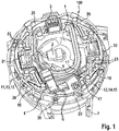
- the horn mechanism 10 is in 1 shown in the installed state within a steering wheel 7.
- the steering wheel 7 accommodates in particular a gas bag module 1 , the horn mechanism 10 being actuated by a relative movement between the gas bag module 1 and the steering wheel 7 . This functionality will be discussed in more detail later.
- the horn mechanism 10 is integrated into a carrier 20 or connected to a carrier 20 . Together with the carrier 20, the horn mechanism 10 forms a horn actuation unit 100.
- the horn actuation unit 100 in particular the carrier 20, is firmly connected to the steering wheel 7.
- the carrier 20 has fastening holes 24 through which screws 26 are guided. The screws 26 engage in the steering wheel 7 so that the horn actuation unit 100 is firmly connected to the steering wheel 7 .
- the carrier 20 has two contact surfaces 21, 22 which extend essentially parallel to the direction of actuation 18 of the horn mechanism 10.
- a first contact surface 21 is provided on a rib or wall 28 arranged perpendicular to a bottom plane 25 of the carrier 20 .
- the rib or the wall 28 is arranged essentially along an inner contour of the carrier 20 .
- a second contact surface 22 is provided along an outer circumference of the carrier 20 .
- the first contact surface 21 and the second contact surface 22 are spaced apart from each other.
- the horn contact groups 11, 12 are arranged on the carrier 20 that the connecting elements 15 of the horn contact groups 11, 12 are each arranged with surface contact on the contact surfaces 21, 22.
- the horn mechanism 10 has a first electrical horn contact group 11 which is formed by a first formed sheet metal part 13 .
- the first formed sheet metal part 13 has a connecting element 15 which is aligned parallel to the first contact surface 21 on the carrier 20 . In the installed state, the connecting element 15 of the first horn contact group 11 rests flush against the first contact surface 21 .
- the first horn contact group 11 also includes a plurality of contact elements 16 which extend at right angles to the connecting element 15 and interact with receiving elements 23 of the carrier 20 .
- the receiving elements 23 enable positioning of the contact elements 16.
- the receiving elements 23 can be designed as snap hooks, so that a positive connection between the first formed sheet metal part 12 and the carrier 20 is produced by attaching the contact elements 16.
- the contact elements 16 form freely swinging ends which at least partially overlap with the contact elements 16 of the second horn contact group 12 .
- the contact elements 16 of the first horn contact group 11 and the second horn contact group 12 overlap at least in sections, in particular in sections one above the other in the direction of actuation of the horn mechanism 10 .
- the second formed sheet metal part 14 which forms the second horn contact group 12 , is designed essentially analogously to the first formed sheet metal part 13 .
- the second formed sheet metal part 14 includes a plurality of contact elements 16 which extend parallel to a bottom plane 25 of the carrier 20 .
- a connecting element 15 which is integrally connected to the contact elements 16 extends perpendicularly to the bottom plane 25 of the carrier 20 .
- the connecting element 15 is specifically aligned parallel to the actuation direction 18 of the horn mechanism 10 .
- both horn contact groups 11, 12 or formed sheet metal parts 13, 14 are firmly connected to the carrier 20, in particular positively connected.
- the carrier 20 is preferably a carrier that is separate from the gas bag module 1 and from the steering wheel 7, so that a separate, preassembled horn actuation unit 100 is produced. Later, the horn actuation unit 100 can then optionally be firmly connected to the gas bag module 1 or the steering wheel 7 via the carrier 20 .
- both formed sheet metal parts 13, 14 each have a connecting element 17.
- the connecting element 17 forms a plug-in contact, in particular in the form of a flat plug, which is aligned essentially perpendicularly to the contact elements 16.
- the connection element 17 extends in the actuation direction 18 of the horn mechanism 10.
- the carrier 20 has a connection socket 5 which accommodates the connection elements 17 of the formed sheet metal parts 13 , 14 .
- connection socket 5 is also electrically connected to a functional plug 4 .
- the electrical connection between the connection socket 5 and the functional plug 4 is made via a connecting cable 6.
- the functional plug 4 also accommodates further connecting cables which, for example, transmit signals from actuating elements on a multifunction steering wheel.
- the function plug 4 thus enables all functions within a steering wheel to be connected to the vehicle.
- a cable runs from the function plug 4 to a steering wheel plug 3, which enables the steering wheel to be electrically connected to a vehicle as a whole.
- the steering wheel connector 3 is additionally coupled to a module connector 2 via corresponding electrical lines, which enables an electrical connection of the gas bag module 1 to the vehicle electrical system.
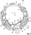
- the carrier 20 into which the horn mechanism 10 is integrated can be seen.
- the horn mechanism 10 comprises two sheet metal parts 13, 14, each of which forms a connecting element 15 and a plurality of contact elements 16.
- the formed sheet metal parts 13, 14 are each formed in one piece.
- Each sheet metal part 13, 14 forms a horn contact group 11, 12.
- connection elements 17, which are designed essentially as plug connectors, are clearly visible.
- the multiple angled structure of the formed sheet metal parts 13, 14 is also visible. It becomes clear that the use of formed sheet metal parts, which can easily be adapted to complex shape specifications, enables good use of space in the area of the carrier 20 becomes.
- an improved miniaturization of the horn actuation unit is achieved through the use of formed sheet metal parts 13, 14 with the connecting elements standing essentially upright on the bottom plane 25 of the carrier 20.
- the flat sheet metal sections of the formed sheet metal parts 13, 14 are predominantly, ie at least 50%, in particular at least 75%, aligned parallel to the direction of actuation in order to achieve a particularly compact design.
- the only exceptions are the resilient contact elements 16 and optional connection elements 17 and/or receiving elements 23, which extend in a plane perpendicular to the direction of actuation 18.
- the fastening holes 24 are also clearly visible, which are provided for the fixed connection of the carrier 20 or the horn actuation unit 100 as a whole to a steering wheel 7 .
- the horn actuation unit 100 can be firmly connected not only to a steering wheel 7 but also to an airbag module 1 .
- the horn actuation unit 100 can therefore be permanently attached either to the airbag module 1 or to the steering wheel 7 . This is essentially irrelevant for the function of the horn actuation unit 100 .
- the bottom plane 25 of the carrier 20 extends essentially perpendicularly to the actuation direction 18, with the first contact surface 21 of the carrier 20 being aligned approximately at right angles to the bottom plane 25 and adapted to the shape of the connecting element 15 of the first horn contact group 11, and the second contact surface 22 of the carrier 20 being aligned approximately at right angles to the floor plane 25 and adapted to the shape of the connecting element 15 of the second horn contact group 12 .
- the carrier 20 has a carrier base 27 defined by the base plane 25, with the rib or wall 28 with the first contact surface 21 starting from the carrier base 27 opposite to the direction of actuation 18 and a carrier wall with the second contact surface 21 starting from the carrier base 27 in the direction of actuation 18 extends. Consequently, the connecting element 15 of the first horn contact group 11 and the connecting element 15 of the second horn contact group 12 are arranged offset with respect to the actuation direction 18 . According to figure 2 have the connecting elements 15 of the two horn contact groups 11, 12, seen in the direction of actuation 18, no overlap, but are even slightly spaced from each other.
- the roughly C-shaped or U-shaped horn contact groups 11, 12 can be mounted with particularly little effort on the approximately circular-cylindrical carrier 20 by simply being pushed radially onto the carrier 20 from the outside (one above the other in the actuation direction 18). In contrast, assembly from radially inward and/or assembly overlapping in actuation direction 18 would be significantly more complex.
- the functioning of the horn actuation unit is based on providing a circuit, in particular a horn circuit, which is interrupted in a rest state and is closed by touching the contact elements 16 of different horn contact groups 11, 12. This allows the current to flow and the acoustic warning signal is triggered.
- the mutually associated contact elements 16 of the first formed sheet metal part 13 and the second formed sheet metal part 14 are arranged at a distance from one another.
- the contact elements 16 each form cantilever spring elements, they are flexible and can thus move relative to one another.
- the relative movement of the contact elements 16 is initiated by a relative movement between the airbag module 1 and the steering wheel 7 .
- actuating extensions are preferably arranged on the gas bag module 1, which are aligned substantially congruently or overlapping over the contact elements 16 assigned to one another. Due to a relative movement between the gas bag module 1 and the steering wheel 7, with the gas bag module 1 dipping into the steering wheel 7, the actuating extensions of the gas bag module 1 press on the contact elements 16 of the first formed sheet metal part 13 or the first horn contact group 11.
- the contact elements 16 of the first horn contact group 11 are thereby deflected and move at least in sections relative to the contact element 16 of the second horn contact group 12 . As soon as the contact elements 16 of the first horn contact group 11 and the second horn contact group 12 touch, the horn circuit is closed and the acoustic warning signal sounds.
Landscapes
- Physics & Mathematics (AREA)
- Acoustics & Sound (AREA)
- Engineering & Computer Science (AREA)
- Mechanical Engineering (AREA)
- Air Bags (AREA)
Claims (12)
- Unité d'actionnement d'avertisseur sonore (100), notamment pour un volant de direction de véhicule (7) équipé d'un module airbag (1), comprenantun premier groupe de contact électrique d'avertisseur sonore (11) et un deuxième groupe de contact électrique d'avertisseur sonore (12), qui présentent chacun au moins deux éléments de contact (16) reliés électriquement par un élément de liaison (15),pour lequel les éléments de contact (16) des groupes de contacts d'avertisseur sonore (11, 12) sont mobiles l'un par rapport à l'autre le long d'une direction d'actionnement (18) de telle sorte qu'au moins deux éléments de contact (16) associés l'un à l'autre du premier et du deuxième groupe de contacts d'avertisseur sonore (11, 12) peuvent se toucher pour fermer un circuit électrique d'avertisseur sonore, etpour lequel l'élément de liaison (15) du premier groupe de contact d'avertisseur sonore (11) et du deuxième groupe de contact d'avertisseur sonore (12) est formé respectivement par une pièce en tôle formée (13, 14),pour lequel un support (20) est prévu, avec un fond plan (25) qui s'étend sensiblement perpendiculairement à la direction d'actionnement (18),caractérisé en ce que l'élément de liaison (15) du premier groupe de contacts d'avertisseur sonore (11) et du deuxième groupe de contacts d'avertisseur sonore (12) est orienté respectivement parallèlement à la direction d'actionnement (18), et en ce quel'élément de liaison (15) du premier groupe de contact électrique d'avertisseur sonore (11) s'appuie sur une première surface d'appui (21) du support (20), qui est orientée sensiblement perpendiculairement au fond plan (25) du support (20) et est adaptée à la forme de l'élément de liaison (15) du premier groupe de contact d'avertisseur sonore (11),pour lequel l'élément de liaison (15) du deuxième groupe de contacts électriques d'avertisseur sonore (12) s'appuie sur une deuxième surface d'appui (22) du support (20), qui est orientée sensiblement perpendiculairement au fond plan (25) du support (20) et est adaptée à la forme de l'élément de liaison (15) du deuxième groupe de contacts d'avertisseur sonore (12),pour lequel la première surface d'appui (21) et la deuxième surface d'appui (22) sont disposées à une certaine distance l'une de l'autre transversalement à la direction d'actionnement (18).
- Unité d'actionnement d'avertisseur sonore (100) selon la revendication 1, caractérisée en ce que la pièce en tôle formée (13, 14) forme d'un seul tenant l'élément de liaison (15) et au moins un élément de contact (16), en particulier pour lequel la pièce en tôle formée (13, 14) forme d'un seul tenant au moins deux éléments de contact (16) disposés à distance l'un de l'autre perpendiculairement à la direction d'actionnement (18).
- Unité d'actionnement d'avertisseur sonore (100) selon l'une des revendications précédentes, caractérisée en ce que l'élément de liaison (15) est une section de tôle plate qui s'étend dans la direction d'actionnement (18), et l'élément de contact (16) est une section de tôle plate qui s'étend dans un plan perpendiculaire à la direction d'actionnement (18).
- Unité d'actionnement d'avertisseur sonore (100) selon l'une des revendications précédentes, caractérisée en ce que les éléments de contact (16) respectivement associés les uns aux autres du premier groupe de contact d'avertisseur sonore (11) et du deuxième groupe de contact d'avertisseur sonore (12) sont disposés les uns au-dessus des autres dans la direction d'actionnement (18).
- Unité d'actionnement d'avertisseur sonore (100) selon l'une des revendications précédentes, caractérisée en ce que la pièce en tôle formée (13, 14) forme un élément de connexion (17) pour la connexion électrique avec une douille de connexion électrique (5), en particulier pour laquelle l'élément de connexion (17) est formé sur un élément de contact (16).
- Unité d'actionnement d'avertisseur sonore (100) selon l'une des revendications précédentes, caractérisée en ce que le support (20) présente un fond de support (27) défini par le fond plan (25), pour lequel un élément de contact (16) du premier groupe de contact d'avertisseur sonore (11) et un élément de contact (16) du deuxième groupe de contact d'avertisseur sonore (12) associé à la fermeture d'un circuit électrique d'avertisseur sonore sont disposés du même côté du fond de support (27).
- Unité d'actionnement d'avertisseur sonore (100) selon l'une des revendications précédentes, caractérisée en ce que le support (20) présente un fond de support (27) défini par le fond plan (25), pour lequel la première surface d'appui (21) s'étend à partir du fond de support (27) en sens inverse du sens d'actionnement (18) et la deuxième surface d'appui (21) s'étend à partir du fond de support (27) dans le sens d'actionnement (18).
- Unité d'actionnement d'avertisseur sonore (100) selon l'une des revendications précédentes, caractérisée en ce que l'élément de liaison (15) du premier groupe de contact d'avertisseur sonore (11) et l'élément de liaison (15) du deuxième groupe de contact d'avertisseur sonore (12) sont décalés l'un par rapport à l'autre par rapport à la direction d'actionnement (18).
- Unité d'actionnement d'avertisseur sonore (100) selon l'une des revendications précédentes, caractérisée en ce que le support (20), au moins dans la zone de la surface d'appui (21, 22), est constitué d'un matériau non conducteur de l'électricité, notamment en matière plastique.
- Unité d'actionnement d'avertisseur sonore (100) selon l'une des revendications précédentes, caractérisée en ce que le premier groupe de contacts d'avertisseur sonore (11) et le deuxième groupe de contacts d'avertisseur sonore (12) sont disposés sur le support (20).
- Module airbag (1), en particulier module airbag conducteur, avec une unité d'actionnement d'avertisseur sonore (100) selon l'une des revendications précédentes, pour lequel un support (20) de l'unité d'actionnement d'avertisseur sonore (100) est relié fixement au module airbag (1).
- Volant de direction équipé d'une unité de commande d'avertisseur sonore (100) selon l'une quelconque des revendications 1 à 10, pour lequel un support (20) de l'unité de commande d'avertisseur sonore (100) est solidaire du volant de direction (7).
Applications Claiming Priority (2)
| Application Number | Priority Date | Filing Date | Title |
|---|---|---|---|
| DE102017102217.1A DE102017102217A1 (de) | 2017-02-06 | 2017-02-06 | Hupenbetätigungseinheit |
| PCT/EP2018/050950 WO2018141540A1 (fr) | 2017-02-06 | 2018-01-16 | Unité d'actionnement d'avertisseur sonore |
Publications (2)
| Publication Number | Publication Date |
|---|---|
| EP3576984A1 EP3576984A1 (fr) | 2019-12-11 |
| EP3576984B1 true EP3576984B1 (fr) | 2022-08-10 |
Family
ID=60997495
Family Applications (1)
| Application Number | Title | Priority Date | Filing Date |
|---|---|---|---|
| EP18700583.0A Active EP3576984B1 (fr) | 2017-02-06 | 2018-01-16 | Unité d'actionnement d'avertisseur sonore |
Country Status (3)
| Country | Link |
|---|---|
| EP (1) | EP3576984B1 (fr) |
| DE (1) | DE102017102217A1 (fr) |
| WO (1) | WO2018141540A1 (fr) |
Families Citing this family (1)
| Publication number | Priority date | Publication date | Assignee | Title |
|---|---|---|---|---|
| CN215904583U (zh) * | 2021-06-30 | 2022-02-25 | 奥托立夫开发公司 | 方向盘组件 |
Family Cites Families (11)
| Publication number | Priority date | Publication date | Assignee | Title |
|---|---|---|---|---|
| IT1308842B1 (it) * | 1999-09-24 | 2002-01-11 | Gallino Plasturgia S R L | Dispositivo di azionamento di avvisatore acustico per un volante diazionamento. |
| JP2002166813A (ja) | 2000-11-30 | 2002-06-11 | T S Tec Kk | エアバッグモジュールを備えたステアリングホイール |
| ITTO20010784A1 (it) * | 2001-08-03 | 2003-02-03 | Breed Automotive Tech | Dispositivo di azionamento di avvisatore acustico per un volante di autoveicolo. |
| DE20219729U1 (de) * | 2002-12-18 | 2003-03-06 | Takata Petri Ag | Vorrichtung zur Betätigung von elektrischen Funktionsgruppen, insbesondere von Hupen an Lenkrädern von Kraftfahrzeugen |
| DE20315868U1 (de) | 2003-10-15 | 2004-02-26 | Trw Automotive Safety Systems Gmbh | Lenkradhupenkontakteinheit und Baugruppe |
| DE102005002945A1 (de) | 2005-01-18 | 2006-07-27 | Takata-Petri Ag | Generatorträger für ein Fahrerairbagmodul zum Einbauen in ein Lenkrad eines Kraftfahrzeuges |
| ES2304655T3 (es) * | 2005-10-08 | 2008-10-16 | RAFI GMBH & CO. KG | Dispositivo de activacion para una instalacion de señales accionada electricamente. |
| WO2009156153A1 (fr) * | 2008-06-25 | 2009-12-30 | Autoliv Development Ab | Volant de véhicule |
| EP2435274B1 (fr) * | 2009-05-29 | 2013-07-10 | Autoliv Development AB | Contacts de klaxon fixée avec adhésif pour volant de direction |
| DE102011120490A1 (de) | 2011-12-08 | 2013-06-13 | Gm Global Technology Operations, Llc | Anordnung eines Lenkrades und eines mit diesem verbundenen Airbag-Moduls bei einem Kraftfahrzeug |
| DE202014002484U1 (de) * | 2014-03-21 | 2015-06-29 | Dalphi Metal Espana, S.A. | Hupeneinrichtung für ein Lenkrad und Lenkrad mit einer Hupeneinrichtung |
-
2017
- 2017-02-06 DE DE102017102217.1A patent/DE102017102217A1/de not_active Withdrawn
-
2018
- 2018-01-16 WO PCT/EP2018/050950 patent/WO2018141540A1/fr active Application Filing
- 2018-01-16 EP EP18700583.0A patent/EP3576984B1/fr active Active
Also Published As
| Publication number | Publication date |
|---|---|
| WO2018141540A1 (fr) | 2018-08-09 |
| DE102017102217A1 (de) | 2018-08-09 |
| EP3576984A1 (fr) | 2019-12-11 |
Similar Documents
| Publication | Publication Date | Title |
|---|---|---|
| EP1713665B2 (fr) | Support de generateur pour module de sac gonflable a monter dans le volant d'un vehicule | |
| EP1557852B1 (fr) | Volant de véhicule | |
| EP3116751B1 (fr) | Élément de connecteur pour fixer un module de coussin à gaz sur un volant, ensemble comportant d'un tel élément de connecteur et un manchon de positionnement ainsi que volant, module de coussin à gaz, ensemble volant et procédé de fabrication | |
| WO2009153254A1 (fr) | Ensemble détecteur pour véhicule à moteur | |
| EP1398227A1 (fr) | Module de sac gonflable et ensemble comprenant un module de sac gonflable et un volant | |
| DE102015001851A1 (de) | Hupensystem | |
| WO2014191295A1 (fr) | Unité volant | |
| EP3576984B1 (fr) | Unité d'actionnement d'avertisseur sonore | |
| WO2017093517A1 (fr) | Antenne de toit présentant une mise en contact directe entre un film d'antenne et une carte de circuits imprimés | |
| DE19534205C2 (de) | Elektrischer Steckverbinder | |
| DE102016117001B4 (de) | Hupenaktivierungseinrichtung | |
| DE102008000224B4 (de) | Gassackmodul mit Hupvorrichtung | |
| DE102015003473A1 (de) | Hupeneinrichtung für ein lenkrad, lenkrad mit einer derartigen hupeneinrichtung sowie herstellungsverfahren | |
| EP1573763B1 (fr) | Dispositif pour actionner des groupes de fonction electriques, notamment un klaxon monte sur le volant d'un vehicule a moteur | |
| DE102015011828B4 (de) | Befestigungsvorrlchtung, Gassackmodul oder Lenkrad mlt elner solchen Befestigungsvorrlchtung und Montageverfahren | |
| EP0681343B1 (fr) | Système pour le raccordement à la masse de câbles électriques, en particulier à une carrosserie automobile | |
| EP2201643B1 (fr) | Procédé de production d'un système d'antenne de véhicule | |
| EP3069416B1 (fr) | Barrette de raccordement et adaptateurs de borne à ressort | |
| EP1936757B1 (fr) | Système de connecteur à fiches pour un montage mural | |
| EP1905130B1 (fr) | Ressort de contact dans un cadre de support d'un amplificateur d'antenne d'un vehicule | |
| DE102004001899A1 (de) | Sperrkreisanordnung | |
| DE102010019383A1 (de) | Befestigung eines elektronischen Gerätes wie Impedanzwandler oder Verstärker an einer Fahrzeugkarosserie | |
| DE102006026823A1 (de) | Vorrichtung zum Anschluss eines Stegs | |
| DE102016218271A1 (de) | Manteleinheit für eine verstellbare Lenksäule eines Kraftfahrzeugs | |
| EP3766130A1 (fr) | Élément de contact pourvu d'un corps de contact et d'un élément élastique agencé contre ce dernier |
Legal Events
| Date | Code | Title | Description |
|---|---|---|---|
| STAA | Information on the status of an ep patent application or granted ep patent |
Free format text: STATUS: UNKNOWN |
|
| STAA | Information on the status of an ep patent application or granted ep patent |
Free format text: STATUS: THE INTERNATIONAL PUBLICATION HAS BEEN MADE |
|
| PUAI | Public reference made under article 153(3) epc to a published international application that has entered the european phase |
Free format text: ORIGINAL CODE: 0009012 |
|
| STAA | Information on the status of an ep patent application or granted ep patent |
Free format text: STATUS: REQUEST FOR EXAMINATION WAS MADE |
|
| 17P | Request for examination filed |
Effective date: 20190906 |
|
| AK | Designated contracting states |
Kind code of ref document: A1 Designated state(s): AL AT BE BG CH CY CZ DE DK EE ES FI FR GB GR HR HU IE IS IT LI LT LU LV MC MK MT NL NO PL PT RO RS SE SI SK SM TR |
|
| AX | Request for extension of the european patent |
Extension state: BA ME |
|
| RAP1 | Party data changed (applicant data changed or rights of an application transferred) |
Owner name: ZF AUTOMOTIVE SAFETY GERMANY GMBH |
|
| DAV | Request for validation of the european patent (deleted) | ||
| DAX | Request for extension of the european patent (deleted) | ||
| GRAP | Despatch of communication of intention to grant a patent |
Free format text: ORIGINAL CODE: EPIDOSNIGR1 |
|
| RIC1 | Information provided on ipc code assigned before grant |
Ipc: B60Q 5/00 20060101AFI20220221BHEP |
|
| STAA | Information on the status of an ep patent application or granted ep patent |
Free format text: STATUS: GRANT OF PATENT IS INTENDED |
|
| INTG | Intention to grant announced |
Effective date: 20220331 |
|
| GRAS | Grant fee paid |
Free format text: ORIGINAL CODE: EPIDOSNIGR3 |
|
| GRAA | (expected) grant |
Free format text: ORIGINAL CODE: 0009210 |
|
| STAA | Information on the status of an ep patent application or granted ep patent |
Free format text: STATUS: THE PATENT HAS BEEN GRANTED |
|
| AK | Designated contracting states |
Kind code of ref document: B1 Designated state(s): AL AT BE BG CH CY CZ DE DK EE ES FI FR GB GR HR HU IE IS IT LI LT LU LV MC MK MT NL NO PL PT RO RS SE SI SK SM TR |
|
| REG | Reference to a national code |
Ref country code: AT Ref legal event code: REF Ref document number: 1510289 Country of ref document: AT Kind code of ref document: T Effective date: 20220815 Ref country code: CH Ref legal event code: EP |
|
| REG | Reference to a national code |
Ref country code: DE Ref legal event code: R096 Ref document number: 502018010343 Country of ref document: DE |
|
| REG | Reference to a national code |
Ref country code: IE Ref legal event code: FG4D Free format text: LANGUAGE OF EP DOCUMENT: GERMAN |
|
| REG | Reference to a national code |
Ref country code: NL Ref legal event code: MP Effective date: 20220810 |
|
| REG | Reference to a national code |
Ref country code: DE Ref legal event code: R082 Ref document number: 502018010343 Country of ref document: DE Representative=s name: MEHNERT, BERNHARD, DE |
|
| REG | Reference to a national code |
Ref country code: LT Ref legal event code: MG9D |
|
| PG25 | Lapsed in a contracting state [announced via postgrant information from national office to epo] |
Ref country code: SE Free format text: LAPSE BECAUSE OF FAILURE TO SUBMIT A TRANSLATION OF THE DESCRIPTION OR TO PAY THE FEE WITHIN THE PRESCRIBED TIME-LIMIT Effective date: 20220810 Ref country code: RS Free format text: LAPSE BECAUSE OF FAILURE TO SUBMIT A TRANSLATION OF THE DESCRIPTION OR TO PAY THE FEE WITHIN THE PRESCRIBED TIME-LIMIT Effective date: 20220810 Ref country code: PT Free format text: LAPSE BECAUSE OF FAILURE TO SUBMIT A TRANSLATION OF THE DESCRIPTION OR TO PAY THE FEE WITHIN THE PRESCRIBED TIME-LIMIT Effective date: 20221212 Ref country code: NO Free format text: LAPSE BECAUSE OF FAILURE TO SUBMIT A TRANSLATION OF THE DESCRIPTION OR TO PAY THE FEE WITHIN THE PRESCRIBED TIME-LIMIT Effective date: 20221110 Ref country code: NL Free format text: LAPSE BECAUSE OF FAILURE TO SUBMIT A TRANSLATION OF THE DESCRIPTION OR TO PAY THE FEE WITHIN THE PRESCRIBED TIME-LIMIT Effective date: 20220810 Ref country code: LV Free format text: LAPSE BECAUSE OF FAILURE TO SUBMIT A TRANSLATION OF THE DESCRIPTION OR TO PAY THE FEE WITHIN THE PRESCRIBED TIME-LIMIT Effective date: 20220810 Ref country code: LT Free format text: LAPSE BECAUSE OF FAILURE TO SUBMIT A TRANSLATION OF THE DESCRIPTION OR TO PAY THE FEE WITHIN THE PRESCRIBED TIME-LIMIT Effective date: 20220810 Ref country code: FI Free format text: LAPSE BECAUSE OF FAILURE TO SUBMIT A TRANSLATION OF THE DESCRIPTION OR TO PAY THE FEE WITHIN THE PRESCRIBED TIME-LIMIT Effective date: 20220810 |
|
| PG25 | Lapsed in a contracting state [announced via postgrant information from national office to epo] |
Ref country code: PL Free format text: LAPSE BECAUSE OF FAILURE TO SUBMIT A TRANSLATION OF THE DESCRIPTION OR TO PAY THE FEE WITHIN THE PRESCRIBED TIME-LIMIT Effective date: 20220810 Ref country code: IS Free format text: LAPSE BECAUSE OF FAILURE TO SUBMIT A TRANSLATION OF THE DESCRIPTION OR TO PAY THE FEE WITHIN THE PRESCRIBED TIME-LIMIT Effective date: 20221210 Ref country code: HR Free format text: LAPSE BECAUSE OF FAILURE TO SUBMIT A TRANSLATION OF THE DESCRIPTION OR TO PAY THE FEE WITHIN THE PRESCRIBED TIME-LIMIT Effective date: 20220810 Ref country code: GR Free format text: LAPSE BECAUSE OF FAILURE TO SUBMIT A TRANSLATION OF THE DESCRIPTION OR TO PAY THE FEE WITHIN THE PRESCRIBED TIME-LIMIT Effective date: 20221111 |
|
| PG25 | Lapsed in a contracting state [announced via postgrant information from national office to epo] |
Ref country code: SM Free format text: LAPSE BECAUSE OF FAILURE TO SUBMIT A TRANSLATION OF THE DESCRIPTION OR TO PAY THE FEE WITHIN THE PRESCRIBED TIME-LIMIT Effective date: 20220810 Ref country code: RO Free format text: LAPSE BECAUSE OF FAILURE TO SUBMIT A TRANSLATION OF THE DESCRIPTION OR TO PAY THE FEE WITHIN THE PRESCRIBED TIME-LIMIT Effective date: 20220810 Ref country code: ES Free format text: LAPSE BECAUSE OF FAILURE TO SUBMIT A TRANSLATION OF THE DESCRIPTION OR TO PAY THE FEE WITHIN THE PRESCRIBED TIME-LIMIT Effective date: 20220810 Ref country code: DK Free format text: LAPSE BECAUSE OF FAILURE TO SUBMIT A TRANSLATION OF THE DESCRIPTION OR TO PAY THE FEE WITHIN THE PRESCRIBED TIME-LIMIT Effective date: 20220810 Ref country code: CZ Free format text: LAPSE BECAUSE OF FAILURE TO SUBMIT A TRANSLATION OF THE DESCRIPTION OR TO PAY THE FEE WITHIN THE PRESCRIBED TIME-LIMIT Effective date: 20220810 |
|
| REG | Reference to a national code |
Ref country code: DE Ref legal event code: R097 Ref document number: 502018010343 Country of ref document: DE |
|
| PG25 | Lapsed in a contracting state [announced via postgrant information from national office to epo] |
Ref country code: SK Free format text: LAPSE BECAUSE OF FAILURE TO SUBMIT A TRANSLATION OF THE DESCRIPTION OR TO PAY THE FEE WITHIN THE PRESCRIBED TIME-LIMIT Effective date: 20220810 Ref country code: EE Free format text: LAPSE BECAUSE OF FAILURE TO SUBMIT A TRANSLATION OF THE DESCRIPTION OR TO PAY THE FEE WITHIN THE PRESCRIBED TIME-LIMIT Effective date: 20220810 |
|
| PLBE | No opposition filed within time limit |
Free format text: ORIGINAL CODE: 0009261 |
|
| STAA | Information on the status of an ep patent application or granted ep patent |
Free format text: STATUS: NO OPPOSITION FILED WITHIN TIME LIMIT |
|
| PG25 | Lapsed in a contracting state [announced via postgrant information from national office to epo] |
Ref country code: AL Free format text: LAPSE BECAUSE OF FAILURE TO SUBMIT A TRANSLATION OF THE DESCRIPTION OR TO PAY THE FEE WITHIN THE PRESCRIBED TIME-LIMIT Effective date: 20220810 |
|
| 26N | No opposition filed |
Effective date: 20230511 |
|
| P01 | Opt-out of the competence of the unified patent court (upc) registered |
Effective date: 20230628 |
|
| PG25 | Lapsed in a contracting state [announced via postgrant information from national office to epo] |
Ref country code: SI Free format text: LAPSE BECAUSE OF FAILURE TO SUBMIT A TRANSLATION OF THE DESCRIPTION OR TO PAY THE FEE WITHIN THE PRESCRIBED TIME-LIMIT Effective date: 20220810 |
|
| REG | Reference to a national code |
Ref country code: CH Ref legal event code: PL |
|
| GBPC | Gb: european patent ceased through non-payment of renewal fee |
Effective date: 20230116 |
|
| PG25 | Lapsed in a contracting state [announced via postgrant information from national office to epo] |
Ref country code: LU Free format text: LAPSE BECAUSE OF NON-PAYMENT OF DUE FEES Effective date: 20230116 |
|
| REG | Reference to a national code |
Ref country code: BE Ref legal event code: MM Effective date: 20230131 |
|
| PG25 | Lapsed in a contracting state [announced via postgrant information from national office to epo] |
Ref country code: LI Free format text: LAPSE BECAUSE OF NON-PAYMENT OF DUE FEES Effective date: 20230131 Ref country code: GB Free format text: LAPSE BECAUSE OF NON-PAYMENT OF DUE FEES Effective date: 20230116 Ref country code: CH Free format text: LAPSE BECAUSE OF NON-PAYMENT OF DUE FEES Effective date: 20230131 |
|
| PG25 | Lapsed in a contracting state [announced via postgrant information from national office to epo] |
Ref country code: BE Free format text: LAPSE BECAUSE OF NON-PAYMENT OF DUE FEES Effective date: 20230131 |
|
| PG25 | Lapsed in a contracting state [announced via postgrant information from national office to epo] |
Ref country code: IE Free format text: LAPSE BECAUSE OF NON-PAYMENT OF DUE FEES Effective date: 20230116 |
|
| PGFP | Annual fee paid to national office [announced via postgrant information from national office to epo] |
Ref country code: FR Payment date: 20231212 Year of fee payment: 7 |
|
| REG | Reference to a national code |
Ref country code: AT Ref legal event code: MM01 Ref document number: 1510289 Country of ref document: AT Kind code of ref document: T Effective date: 20230116 |
|
| PG25 | Lapsed in a contracting state [announced via postgrant information from national office to epo] |
Ref country code: AT Free format text: LAPSE BECAUSE OF NON-PAYMENT OF DUE FEES Effective date: 20230116 |
|
| PG25 | Lapsed in a contracting state [announced via postgrant information from national office to epo] |
Ref country code: AT Free format text: LAPSE BECAUSE OF NON-PAYMENT OF DUE FEES Effective date: 20230116 |
|
| PGFP | Annual fee paid to national office [announced via postgrant information from national office to epo] |
Ref country code: DE Payment date: 20240131 Year of fee payment: 7 |