EP2201223B1 - Brennkraftmaschine mit zumindest einem zylinder mit einer drehsteifen nockenwelle - Google Patents
Brennkraftmaschine mit zumindest einem zylinder mit einer drehsteifen nockenwelle Download PDFInfo
- Publication number
- EP2201223B1 EP2201223B1 EP08804579A EP08804579A EP2201223B1 EP 2201223 B1 EP2201223 B1 EP 2201223B1 EP 08804579 A EP08804579 A EP 08804579A EP 08804579 A EP08804579 A EP 08804579A EP 2201223 B1 EP2201223 B1 EP 2201223B1
- Authority
- EP
- European Patent Office
- Prior art keywords
- camshaft
- combustion engine
- internal combustion
- injection pump
- fuel injection
- Prior art date
- Legal status (The legal status is an assumption and is not a legal conclusion. Google has not performed a legal analysis and makes no representation as to the accuracy of the status listed.)
- Not-in-force
Links
- 238000002485 combustion reaction Methods 0.000 title claims abstract description 12
- 238000002347 injection Methods 0.000 claims abstract description 38
- 239000007924 injection Substances 0.000 claims abstract description 38
- 239000000446 fuel Substances 0.000 claims abstract description 18
- 230000005540 biological transmission Effects 0.000 claims abstract description 14
- RDYMFSUJUZBWLH-UHFFFAOYSA-N endosulfan Chemical compound C12COS(=O)OCC2C2(Cl)C(Cl)=C(Cl)C1(Cl)C2(Cl)Cl RDYMFSUJUZBWLH-UHFFFAOYSA-N 0.000 description 4
- 230000010363 phase shift Effects 0.000 description 2
- 238000004519 manufacturing process Methods 0.000 description 1
Images



Classifications
-
- F—MECHANICAL ENGINEERING; LIGHTING; HEATING; WEAPONS; BLASTING
- F01—MACHINES OR ENGINES IN GENERAL; ENGINE PLANTS IN GENERAL; STEAM ENGINES
- F01L—CYCLICALLY OPERATING VALVES FOR MACHINES OR ENGINES
- F01L1/00—Valve-gear or valve arrangements, e.g. lift-valve gear
- F01L1/34—Valve-gear or valve arrangements, e.g. lift-valve gear characterised by the provision of means for changing the timing of the valves without changing the duration of opening and without affecting the magnitude of the valve lift
-
- F—MECHANICAL ENGINEERING; LIGHTING; HEATING; WEAPONS; BLASTING
- F02—COMBUSTION ENGINES; HOT-GAS OR COMBUSTION-PRODUCT ENGINE PLANTS
- F02M—SUPPLYING COMBUSTION ENGINES IN GENERAL WITH COMBUSTIBLE MIXTURES OR CONSTITUENTS THEREOF
- F02M59/00—Pumps specially adapted for fuel-injection and not provided for in groups F02M39/00 -F02M57/00, e.g. rotary cylinder-block type of pumps
- F02M59/02—Pumps specially adapted for fuel-injection and not provided for in groups F02M39/00 -F02M57/00, e.g. rotary cylinder-block type of pumps of reciprocating-piston or reciprocating-cylinder type
- F02M59/10—Pumps specially adapted for fuel-injection and not provided for in groups F02M39/00 -F02M57/00, e.g. rotary cylinder-block type of pumps of reciprocating-piston or reciprocating-cylinder type characterised by the piston-drive
- F02M59/102—Mechanical drive, e.g. tappets or cams
-
- F—MECHANICAL ENGINEERING; LIGHTING; HEATING; WEAPONS; BLASTING
- F02—COMBUSTION ENGINES; HOT-GAS OR COMBUSTION-PRODUCT ENGINE PLANTS
- F02M—SUPPLYING COMBUSTION ENGINES IN GENERAL WITH COMBUSTIBLE MIXTURES OR CONSTITUENTS THEREOF
- F02M59/00—Pumps specially adapted for fuel-injection and not provided for in groups F02M39/00 -F02M57/00, e.g. rotary cylinder-block type of pumps
- F02M59/20—Varying fuel delivery in quantity or timing
- F02M59/24—Varying fuel delivery in quantity or timing with constant-length-stroke pistons having variable effective portion of stroke
Definitions
- the invention relates to an internal combustion engine having at least one cylinder with a camshaft for actuating at least one gas exchange valve via a push rod and a valve lever, wherein a gas exchange cam of the camshaft acts on the push rod via an adjustable transmission lever.
- the DE 10 2004 057 438 A1 describes a valve train for gas exchange valves of an internal combustion engine with an adjustable rocker arm, which cooperates on the one hand with an eccentric shaft and on the other hand with a roller running on a cam of a camshaft.
- the valve drive has at least one rocker arm, wherein the rocker arm acts with a first end on a gas exchange valve and is pivotally connected to a second end, each with a push rod.
- the adjustable rocker arm is articulated to the eccentric shaft that is adjusted by the eccentric adjustable by an eccentric eccentric having a comparatively large Exzentereconomic, a desired and predeterminable as a design parameter phase shift with a maximum Phasenverstellwinkel and a predetermined maximum valve lift and the base of the push rod on the adjustable rocker arm during the phase shift approximately follows the pivot radius of the push rod around the upper pivot point on the linkage on the rocker arm.
- the object of the invention is to avoid these disadvantages and to adjust in the simplest possible way both the timing of the gas exchange valves and the injection timing.
- a structurally particularly simple adjustment of the timing of the gas exchange valves can be achieved if the axis of rotation of the transmission lever is adjustable by means of an eccentric shaft. It is provided in a simple embodiment that the timing of the intake and exhaust valves can be adjusted by a single eccentric shaft. In order to allow a separate adjustment of the timing for intake and exhaust valves, provides a constructive development of the invention, that in each case a separate eccentric shaft is provided for intake valves and exhaust valves.
- the gas exchange valves and the fuel injection pump can be driven by a single camshaft.
- a purely mechanical fuel injection pump is used, which keeps the cost very small. Due to the rotation of the camshaft via the phaser a large adjustment range for the fuel injection pump can be achieved.
- the adjustment range of the camshaft can be, for example, +/- 15 ° camshaft angle.
- Fig. 1 shows two gas exchange valves 1, 2 of an internal combustion engine, which are driven by a lower camshaft 6 via a rocker arm 3a, a push rod 4a and a transmission lever 5a. Trained as a drag lever transmission lever 5a is mounted on a rotatable eccentric shaft 7. By rotating the eccentric shaft 7 with the eccentricity a, the transmission lever 5a is reciprocated, whereby the rotation axis 5 'of the transmission lever 5a shifts. As a result, the phase change for the gas exchange valves 1, 2 of the valve lift curve h within the in Fig. 5 illustrated adjustment range.
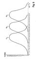
- Fig. 5 shows the valve lift h applied to the camshaft angle ⁇ , where h 2, the basic position of the valve lift h is designated.
- the lift curve is in the embodiment in the range of -15 ° to + 15 ° camshaft angle ⁇ adjustable.
- the corresponding extreme positions of the lifting curves are designated h 1 and h 3 .
- the gas exchange cams 8a, 8b act on the transmission levers 5a, 5b via rollers 9a, 9b.
- an injection cam 10 is further arranged for actuating a mechanical fuel injection pump 11, as shown in Fig. 2 evident.
- a phaser 12 is arranged at one end of the camshaft over which the injection time of the fuel injection pump 11 within a cam angle range ⁇ from -15 ° to + 15 ° camshaft angle ⁇ is adjustable, as shown in Fig. 6 evident.
- Fig. 6 is the Einspritzpumpenhub H plotted against the camshaft angle ⁇ .
- H 2 designates the basic position of the injection pump stroke H, by which the injection time of the fuel injection pump 11 can be adjusted within the range of the camshaft angle from -15 ° to + 15 °.
- the outermost portions of the injection pump stroke H are in Fig. 6 designated H 1 and H 3 .
- the distance between the transmission lever 5a, 5b and the rocker arm 3a, 3b changes because the movement of the transmission lever 5a, 5b on the base circle 6a of the camshaft 6 is reciprocated and the contact point between gas exchange cam 8a, 8b and transmission lever 5a, 5b along the base circle 6a wanders.
Landscapes
- Engineering & Computer Science (AREA)
- Mechanical Engineering (AREA)
- General Engineering & Computer Science (AREA)
- Chemical & Material Sciences (AREA)
- Combustion & Propulsion (AREA)
- Valve-Gear Or Valve Arrangements (AREA)
- Valve Device For Special Equipments (AREA)
- Fuel-Injection Apparatus (AREA)
Abstract
Description
- Die Erfindung betrifft eine Brennkraftmaschine mit zumindest einem Zylinder mit einer Nockenwelle zur Betätigung von zumindest einem Gaswechselventil über eine Stößelstange und einen Ventilhebel, wobei ein Gaswechselnocken der Nockenwelle über einen verstellbaren Übertragungshebel auf die Stößelstange einwirkt.
- Die
DE 10 2004 057 438 A1 beschreibt einen Ventiltrieb für Gaswechselventile einer Brennkraftmaschine mit einem verstellbaren Schwinghebel, der einerseits mit einer Exzenterwelle und andererseits mit einer auf einem Nocken einer Nockenwelle laufenden Rolle zusammenwirkt. Der Ventiltrieb weist mindestens einen Kipphebel auf, wobei der Kipphebel mit einem ersten Ende auf ein Gaswechselventil einwirkt und mit einem zweiten Ende mit jeweils einer Stößelstange gelenkig verbunden ist. Der verstellbare Schwinghebel ist dabei derart an der Exzenterwelle angelenkt, dass durch den um einen Exzenterwinkel verstellbaren Exzenter, der ein vergleichsweise großes Exzentermaß aufweist, eine gewünschte und als Konstruktionsparameter vorgebbare Phasenverschiebung mit einem maximalen Phasenverstellwinkel und ein vorgegebener maximaler Ventilhub eingestellt ist und der Stützpunkt der Stößelstange auf den verstellbaren Schwinghebel während der Phasenverschiebung in etwa dem Schwenkradius der Stößelstange um den oberen Drehpunkt an der Anlenkung am Kipphebel folgt. - Aus der
JP 61-058908 A JP60-001354 - Weiters ist es bekannt, zur Verstellung der Steuerzeiten der Ein- und Auslassventile einer Brennkraftmaschine zwei unabhängige Nockenwellen zu verwenden. Des weiteren ist es bekannt, die Kraftstoffeinspritzung elektronisch zu verstellen, was aber den Nachteil hat, dass der Einspritzdruck über den gesamten Verstellbereich am Einspritzventil anliegen muss, weshalb teure Servoventile notwendig sind.
- Aufgabe der Erfindung ist es, diese Nachteile zu vermeiden und auf möglichst einfache Weise sowohl die Steuerzeiten der Gaswechselventile als auch den Einspritzzeitpunkt zu verstellen.
- Erfindungsgemäß wird dies dadurch erreicht, dass die Nockenwelle über einen Einspritznocken eine mechanische Kraftstoffeinspritzpumpe antreibt und dass die Einspritzzeit der Kraftstoffeinspritzpumpe mittels eines auf die Nockenwelle einwirkenden Phasenstellers veränderbar ist, wobei vorzugsweise die Steuerzeiten der Gaswechselventile und die Einspritzzeit der Kraftstoffeinspritzpumpe unabhängig voneinander verstellbar sind.
- Eine konstruktiv besonders einfache Verstellung der Steuerzeiten der Gaswechselventile kann erreicht werden, wenn die Drehachse des Übertragungshebels mittels einer Exzenterwelle verstellbar ist. Dabei ist in einer einfachen Ausführung vorgesehen, dass die Steuerzeiten der Ein- und Auslassventile durch eine einzige Exzenterwelle verstellt werden können. Um eine getrennte Verstellung der Steuerzeiten für Ein- und Auslassventile zu ermöglichen, sieht eine konstruktive Weiterentwicklung der Erfindung vor, dass für Einlassventile und Auslassventile jeweils eine eigene Exzenterwelle vorgesehen ist.
- Gemäß einer herstellungsmäßig besonders einfachen und kostengünstigen Ausführung der Erfindung ist vorgesehen, dass die Gaswechselventile und die Kraftstoffeinspritzpumpe durch eine einzige Nockenwelle antreibbar sind.
- Zum Unterschied zu bekannten Einspritzsystemen wird eine rein mechanische Kraftstoffeinspritzpumpe verwendet, was den Kostenaufwand sehr klein hält. Durch die Verdrehung der Nockenwelle über den Phasensteller kann ein großer Verstellbereich für die Kraftstoffeinspritzpumpe erreicht werden. Der Verstellbereich der Nockenwelle kann dabei beispielsweise +/-15° Nockenwellenwinkel betragen.
- Die Erfindung wird im Folgenden anhand der Figuren näher erläutert. Es zeigen schematisch:
- Fig. 1
- eine Ventilbetätigungseinrichtung einer erfindungsgemäßen Brenn- kraftmaschine in einem Querschnitt;
- Fig. 2
- die Ventilbetätigungseinrichtung in einer Seitenansicht;
- Fig. 3
- die Nockenwelle in einem Schnitt gemäß der Linie III-III in
Fig. 2 ; - Fig. 4
- die Nockenwelle in einem Schnitt gemäß der Linie IV-IV in
Fig. 2 ; - Fig. 5
- den Ventilhub über dem Nockenwellenwinkel; und
- Fig. 6
- den Einspritzpumpenhub über dem Nockenwellenwinkel aufgetra- gen.
-
Fig. 1 zeigt zwei Gaswechselventile 1, 2 einer Brennkraftmaschine, welcher über einen Kipphebel 3a, eine Stößelstange 4a und einen Übertragungshebel 5a durch eine untenliegende Nockenwelle 6 angetrieben werden. Der als Schlepphebel ausgebildete Übertragungshebel 5a ist über eine verdrehbare Exzenterwelle 7 gelagert. Durch Verdrehen der Exzenterwelle 7 mit der Exzentrizität a wird der Übertragungshebel 5a hin- und hergeschoben, wodurch sich die Drehachse 5' des Übertragungshebels 5a verschiebt. Dadurch erreicht man durch die Positionsänderung des Übertragungshebels 5a eine Phasenverschiebung für die Gaswechselventile 1, 2 der Ventilhubkurve h innerhalb des inFig. 5 dargestellten Verstellbereiches.Fig. 5 zeigt dazu die Ventilerhebung h über dem Nockenwellenwinkel α aufgetragen, wobei mit h2 die Grundstellung der Ventilerhebung h bezeichnet ist. Die Hubkurve ist im Ausführungsbeispiel im Bereich von -15° bis +15° Nockenwellenwinkel α verstellbar. Die entsprechenden Extremlagen der Hubkurven sind mit h1 und h3 bezeichnet. - Die Gaswechselnocken 8a, 8b wirken über Rollen 9a, 9b auf die Übertragungshebel 5a, 5b ein.
- Auf der Nockenwelle 6 ist weiters ein Einspritznocken 10 zur Betätigung einer mechanischen Kraftstoffeinspritzpumpe 11 angeordnet, wie aus der
Fig. 2 hervorgeht. Um eine Verstellung der Einspritzzeiten der Einspritzpumpe 11 zu ermöglichen, ist an einem Ende der Nockenwelle ein Phasensteller 12 angeordnet, über welche die Einspritzzeit der Kraftstoffeinspritzpumpe 11 innerhalb eines Nockenwinkelbereiches α von -15° bis +15° Nockenwellenwinkel α verstellbar ist, wie aus derFig. 6 hervorgeht. InFig. 6 ist dabei der Einspritzpumpenhub H über dem Nockenwellenwinkel α aufgetragen. Mit H2 ist die Grundstellung des Einspritzpumpenhubes H bezeichnet, um welchen die Einspritzzeit der Kraftstoffeinspritzpumpe 11 innerhalb des Nockenwellenwinkelbereiches von -15° bis +15° verstellt werden kann. Die äußersten Bereiche des Einspritzpumpenhubes H sind inFig. 6 mit H1 und H3 bezeichnet. - Durch die Verdrehung der Exzenterwelle 7 um einen Winkel γ ändert sich der Abstand zwischen dem Übertragungshebel 5a, 5b und dem Kipphebel 3a, 3b, weil durch die Bewegung der Übertragungshebel 5a, 5b am Grundkreis 6a der Nockenwelle 6 hin- und herbewegt wird und der Kontaktpunkt zwischen Gaswechselnocken 8a, 8b und Übertragungshebel 5a, 5b entlang des Grundkreises 6a wandert.
- Dadurch, dass die Steuerzeitverstellungen der Gaswechselventile 1 und 2, sowie der Einspritzpumpe 11 nur eine Nockenwelle 6 vorgesehen ist, wird der konstruktive Aufwand auf ein Mindestmaß reduziert. Durch die Exzenterwelle 7 und den Phasensteller 12 können trotzdem die Gaswechselventile 1, 2 und die Kraftstoffeinspritzpumpe unabhängig voneinander verstellt werden.
Claims (5)
- Brennkraftmaschine mit zumindest einem Zylinder mit einer Nockenwelle (6) zur Betätigung von zumindest einem Gaswechselventil (1, 2) über eine Stößelstange (4a, 4b) und einen Ventilhebel (3a, 3b), wobei ein Gaswechselnocken (8a, 8b) der Nockenwelle (6) über einen verstellbaren Übertragungshebel (5a, 5b) auf die Stößelstange (4a, 4b) einwirkt, dadurch gekennzeichnet, dass die Nockenwelle (6) über einen Einspritznocken (10) eine mechanische Kraftstoffeinspritzpumpe (11) antreibt und dass die Einspritzzeit der Kraftstoffeinspritzpumpe (11) mittels eines auf die Nockenwelle (6) einwirkenden Phasenstellers (12) veränderbar ist.
- Brennkraftmaschine nach Anspruch 1, dadurch gekennzeichnet, dass die Steuerzeiten der Gaswechselventile (1, 2) und die Einspritzzeit der Kraftstoffeinspritzpumpe (11) unabhängig voneinander verstellbar sind.
- Brennkraftmaschine nach Anspruch 1 oder 2, dadurch gekennzeichnet, dass die Drehachse (5a') des Übertragungshebels (5a, 5b) mittels einer Exzenterwelle (7) verstellbar ist.
- Brennkraftmaschine nach einem der Ansprüche 1 bis 3, dadurch gekennzeichnet, dass für Einlassventile und Auslassventile jeweils eine eigene Exzenterwelle (7) vorgesehen ist.
- Brennkraftmaschine nach einem der Ansprüche 1 bis 4, dadurch gekennzeichnet, dass die Gaswechselventile (1, 2) und die Kraftstoffeinspritzpumpe (11) durch eine einzige Nockenwelle (6) antreibbar sind.
Applications Claiming Priority (2)
| Application Number | Priority Date | Filing Date | Title |
|---|---|---|---|
| AT0162507A AT503893B1 (de) | 2007-10-11 | 2007-10-11 | Brennkraftmaschine mit zumindest einem zylinder mit einer drehsteifen nockenwelle |
| PCT/EP2008/062655 WO2009049996A1 (de) | 2007-10-11 | 2008-09-23 | Brennkraftmaschine mit zumindest einem zylinder mit einer drehsteifen nockenwelle |
Publications (2)
| Publication Number | Publication Date |
|---|---|
| EP2201223A1 EP2201223A1 (de) | 2010-06-30 |
| EP2201223B1 true EP2201223B1 (de) | 2011-04-27 |
Family
ID=38871151
Family Applications (1)
| Application Number | Title | Priority Date | Filing Date |
|---|---|---|---|
| EP08804579A Not-in-force EP2201223B1 (de) | 2007-10-11 | 2008-09-23 | Brennkraftmaschine mit zumindest einem zylinder mit einer drehsteifen nockenwelle |
Country Status (4)
| Country | Link |
|---|---|
| EP (1) | EP2201223B1 (de) |
| AT (2) | AT503893B1 (de) |
| DE (1) | DE502008003375D1 (de) |
| WO (1) | WO2009049996A1 (de) |
Families Citing this family (3)
| Publication number | Priority date | Publication date | Assignee | Title |
|---|---|---|---|---|
| DE102010011419A1 (de) * | 2010-03-15 | 2011-09-15 | Schaeffler Technologies Gmbh & Co. Kg | Antriebseinheit |
| WO2019089491A1 (en) * | 2017-11-03 | 2019-05-09 | Indian Motorcycle International, LLC | Variable valve timing system for an engine |
| CN114352450A (zh) * | 2020-09-29 | 2022-04-15 | 罗伯特·博世有限公司 | 用于燃料喷射泵的凸轮轴 |
Family Cites Families (8)
| Publication number | Priority date | Publication date | Assignee | Title |
|---|---|---|---|---|
| JPS601354A (ja) * | 1983-06-18 | 1985-01-07 | Ikegai Corp | デイ−ゼル機関の燃焼制御装置 |
| JPS6158908A (ja) | 1984-08-31 | 1986-03-26 | Hino Motors Ltd | 内燃機関の可変タイミング動弁装置 |
| JPS61250377A (ja) * | 1985-04-26 | 1986-11-07 | Kubota Ltd | 燃料噴射機関のユニツトインゼクタのプランジヤ駆動装置 |
| US5713335A (en) * | 1995-09-12 | 1998-02-03 | Cummins Engine Company, Inc. | Variable injection timing and injection pressure control arrangement |
| JP3619402B2 (ja) * | 1999-09-10 | 2005-02-09 | ダイハツ工業株式会社 | 2サイクルユニフロー型ディーゼル内燃機関の可変バルブタイミング装置 |
| DE10041466B4 (de) * | 2000-08-23 | 2008-10-09 | Man Diesel Se | Ventiltrieb für Gaswechselventile einer Brennkraftmaschine |
| JP2003035179A (ja) * | 2001-07-25 | 2003-02-07 | Sanshin Ind Co Ltd | 船外機用4サイクルエンジン |
| DE102004057438A1 (de) | 2004-11-27 | 2006-06-01 | Man B & W Diesel Ag | Ventiltrieb für Gaswechselventile einer Brennkraftmaschine mit einem verstellbaren Schwinghebel, der einerseits mit einer Exzenterwelle und andererseits mit einer auf einem Nocken einer Nockenwelle laufenden Rolle zusammenwirkt |
-
2007
- 2007-10-11 AT AT0162507A patent/AT503893B1/de not_active IP Right Cessation
-
2008
- 2008-09-23 EP EP08804579A patent/EP2201223B1/de not_active Not-in-force
- 2008-09-23 WO PCT/EP2008/062655 patent/WO2009049996A1/de not_active Ceased
- 2008-09-23 AT AT08804579T patent/ATE507372T1/de active
- 2008-09-23 DE DE502008003375T patent/DE502008003375D1/de active Active
Also Published As
| Publication number | Publication date |
|---|---|
| AT503893B1 (de) | 2011-04-15 |
| DE502008003375D1 (de) | 2011-06-09 |
| WO2009049996A1 (de) | 2009-04-23 |
| ATE507372T1 (de) | 2011-05-15 |
| AT503893A2 (de) | 2008-01-15 |
| AT503893A3 (de) | 2010-12-15 |
| EP2201223A1 (de) | 2010-06-30 |
Similar Documents
| Publication | Publication Date | Title |
|---|---|---|
| DE10006018B4 (de) | Variabler Ventiltrieb zur Laststeuerung einer fremdgezündeten Brennkraftmaschine | |
| EP2625395B1 (de) | Viertakt-brennkraftmaschine mit einer motorbremse | |
| DE10314683A1 (de) | Variable Ventilhubsteuerung für einen Verbrennungsmotor mit untenliegender Nockenwelle | |
| DE2006618A1 (de) | Ventilsteuerungseinrichtung fur Brenn kraftmaschinen | |
| DE102012002026A1 (de) | Variabler Ventiltrieb mit Zylinderabschaltung für einen Verbrennungsmotor sowie Verfahren zur Steuerung des Ventiltriebs eines Verbrennungsmotors | |
| DE102005012844B4 (de) | Variable Ventilvorrichtung für einen Verbrennungsmotor | |
| EP2201223B1 (de) | Brennkraftmaschine mit zumindest einem zylinder mit einer drehsteifen nockenwelle | |
| EP0962629A2 (de) | Variabler Ventiltrieb für eine Brennkraftmaschine | |
| DE102016112449B4 (de) | Ventiltrieb für eine Brennkraftmaschine und Brennkraftmaschine | |
| WO2005075797A1 (de) | Schlepphebel zur hubumschaltung | |
| EP0352580B1 (de) | Betätigungsvorrichtung für Ventile einer Brennkraftmaschine | |
| AT510528B1 (de) | Viertakt-brennkraftmaschine mit einer motorbremse | |
| DE102008015218B4 (de) | Ventilmechanismus eines Motors | |
| DE102006002133B4 (de) | Ventiltrieb zur hubvariablen Betätigung eines Gaswechselventils einer Brennkraftmaschine | |
| WO2005026503A2 (de) | Vollvariable hubventilsteuerung | |
| EP1619362B1 (de) | Ventiltrieb einer Brennkraftmaschine | |
| DE4206867C2 (de) | Ventilsteuereinrichtung für Hubkolbenmotoren | |
| DE4230809C2 (de) | Ventilsteuerung für Brennkraftmaschinen | |
| DE102007003967A1 (de) | Ventiltrieb einer Brennkraftmaschine | |
| DE19651806C2 (de) | Ventilbetrieb für Gaswechselventile in Hubkolbenmotoren | |
| EP1288451B1 (de) | Zylinderkopf für eine Hubkolben-Brennkraftmaschine mit einer hubvariablen Ventilsteuerung | |
| EP0947672A2 (de) | Variable Ventilsteuerung für eine Hubkolben-Brennkraftmaschine | |
| AT521445B1 (de) | Variable ventiltriebvorrichtung | |
| DE10119632B4 (de) | Variable Ventilsteuervorrichtung für eine Brennkraftmaschine | |
| DE102005019991A1 (de) | Vollvariable Hubventilsteuerungen für Brennkraftmaschinen |
Legal Events
| Date | Code | Title | Description |
|---|---|---|---|
| PUAI | Public reference made under article 153(3) epc to a published international application that has entered the european phase |
Free format text: ORIGINAL CODE: 0009012 |
|
| 17P | Request for examination filed |
Effective date: 20100412 |
|
| AK | Designated contracting states |
Kind code of ref document: A1 Designated state(s): AT BE BG CH CY CZ DE DK EE ES FI FR GB GR HR HU IE IS IT LI LT LU LV MC MT NL NO PL PT RO SE SI SK TR |
|
| AX | Request for extension of the european patent |
Extension state: AL BA MK RS |
|
| GRAP | Despatch of communication of intention to grant a patent |
Free format text: ORIGINAL CODE: EPIDOSNIGR1 |
|
| DAX | Request for extension of the european patent (deleted) | ||
| GRAS | Grant fee paid |
Free format text: ORIGINAL CODE: EPIDOSNIGR3 |
|
| GRAA | (expected) grant |
Free format text: ORIGINAL CODE: 0009210 |
|
| AK | Designated contracting states |
Kind code of ref document: B1 Designated state(s): AT BE BG CH CY CZ DE DK EE ES FI FR GB GR HR HU IE IS IT LI LT LU LV MC MT NL NO PL PT RO SE SI SK TR |
|
| REG | Reference to a national code |
Ref country code: GB Ref legal event code: FG4D Free format text: NOT ENGLISH |
|
| REG | Reference to a national code |
Ref country code: CH Ref legal event code: EP |
|
| REG | Reference to a national code |
Ref country code: IE Ref legal event code: FG4D Free format text: LANGUAGE OF EP DOCUMENT: GERMAN |
|
| REF | Corresponds to: |
Ref document number: 502008003375 Country of ref document: DE Date of ref document: 20110609 Kind code of ref document: P |
|
| REG | Reference to a national code |
Ref country code: DE Ref legal event code: R096 Ref document number: 502008003375 Country of ref document: DE Effective date: 20110609 |
|
| REG | Reference to a national code |
Ref country code: NL Ref legal event code: VDEP Effective date: 20110427 |
|
| LTIE | Lt: invalidation of european patent or patent extension |
Effective date: 20110427 |
|
| PG25 | Lapsed in a contracting state [announced via postgrant information from national office to epo] |
Ref country code: LT Free format text: LAPSE BECAUSE OF FAILURE TO SUBMIT A TRANSLATION OF THE DESCRIPTION OR TO PAY THE FEE WITHIN THE PRESCRIBED TIME-LIMIT Effective date: 20110427 Ref country code: PT Free format text: LAPSE BECAUSE OF FAILURE TO SUBMIT A TRANSLATION OF THE DESCRIPTION OR TO PAY THE FEE WITHIN THE PRESCRIBED TIME-LIMIT Effective date: 20110829 Ref country code: HR Free format text: LAPSE BECAUSE OF FAILURE TO SUBMIT A TRANSLATION OF THE DESCRIPTION OR TO PAY THE FEE WITHIN THE PRESCRIBED TIME-LIMIT Effective date: 20110427 Ref country code: NO Free format text: LAPSE BECAUSE OF FAILURE TO SUBMIT A TRANSLATION OF THE DESCRIPTION OR TO PAY THE FEE WITHIN THE PRESCRIBED TIME-LIMIT Effective date: 20110727 Ref country code: SE Free format text: LAPSE BECAUSE OF FAILURE TO SUBMIT A TRANSLATION OF THE DESCRIPTION OR TO PAY THE FEE WITHIN THE PRESCRIBED TIME-LIMIT Effective date: 20110427 |
|
| REG | Reference to a national code |
Ref country code: IE Ref legal event code: FD4D |
|
| PG25 | Lapsed in a contracting state [announced via postgrant information from national office to epo] |
Ref country code: ES Free format text: LAPSE BECAUSE OF FAILURE TO SUBMIT A TRANSLATION OF THE DESCRIPTION OR TO PAY THE FEE WITHIN THE PRESCRIBED TIME-LIMIT Effective date: 20110807 Ref country code: IS Free format text: LAPSE BECAUSE OF FAILURE TO SUBMIT A TRANSLATION OF THE DESCRIPTION OR TO PAY THE FEE WITHIN THE PRESCRIBED TIME-LIMIT Effective date: 20110827 Ref country code: LV Free format text: LAPSE BECAUSE OF FAILURE TO SUBMIT A TRANSLATION OF THE DESCRIPTION OR TO PAY THE FEE WITHIN THE PRESCRIBED TIME-LIMIT Effective date: 20110427 Ref country code: GR Free format text: LAPSE BECAUSE OF FAILURE TO SUBMIT A TRANSLATION OF THE DESCRIPTION OR TO PAY THE FEE WITHIN THE PRESCRIBED TIME-LIMIT Effective date: 20110728 Ref country code: CY Free format text: LAPSE BECAUSE OF FAILURE TO SUBMIT A TRANSLATION OF THE DESCRIPTION OR TO PAY THE FEE WITHIN THE PRESCRIBED TIME-LIMIT Effective date: 20110427 Ref country code: SI Free format text: LAPSE BECAUSE OF FAILURE TO SUBMIT A TRANSLATION OF THE DESCRIPTION OR TO PAY THE FEE WITHIN THE PRESCRIBED TIME-LIMIT Effective date: 20110427 |
|
| PG25 | Lapsed in a contracting state [announced via postgrant information from national office to epo] |
Ref country code: NL Free format text: LAPSE BECAUSE OF FAILURE TO SUBMIT A TRANSLATION OF THE DESCRIPTION OR TO PAY THE FEE WITHIN THE PRESCRIBED TIME-LIMIT Effective date: 20110427 |
|
| PG25 | Lapsed in a contracting state [announced via postgrant information from national office to epo] |
Ref country code: CZ Free format text: LAPSE BECAUSE OF FAILURE TO SUBMIT A TRANSLATION OF THE DESCRIPTION OR TO PAY THE FEE WITHIN THE PRESCRIBED TIME-LIMIT Effective date: 20110427 Ref country code: EE Free format text: LAPSE BECAUSE OF FAILURE TO SUBMIT A TRANSLATION OF THE DESCRIPTION OR TO PAY THE FEE WITHIN THE PRESCRIBED TIME-LIMIT Effective date: 20110427 Ref country code: IE Free format text: LAPSE BECAUSE OF FAILURE TO SUBMIT A TRANSLATION OF THE DESCRIPTION OR TO PAY THE FEE WITHIN THE PRESCRIBED TIME-LIMIT Effective date: 20110427 |
|
| PG25 | Lapsed in a contracting state [announced via postgrant information from national office to epo] |
Ref country code: RO Free format text: LAPSE BECAUSE OF FAILURE TO SUBMIT A TRANSLATION OF THE DESCRIPTION OR TO PAY THE FEE WITHIN THE PRESCRIBED TIME-LIMIT Effective date: 20110427 Ref country code: DK Free format text: LAPSE BECAUSE OF FAILURE TO SUBMIT A TRANSLATION OF THE DESCRIPTION OR TO PAY THE FEE WITHIN THE PRESCRIBED TIME-LIMIT Effective date: 20110427 Ref country code: PL Free format text: LAPSE BECAUSE OF FAILURE TO SUBMIT A TRANSLATION OF THE DESCRIPTION OR TO PAY THE FEE WITHIN THE PRESCRIBED TIME-LIMIT Effective date: 20110427 Ref country code: SK Free format text: LAPSE BECAUSE OF FAILURE TO SUBMIT A TRANSLATION OF THE DESCRIPTION OR TO PAY THE FEE WITHIN THE PRESCRIBED TIME-LIMIT Effective date: 20110427 |
|
| PLBE | No opposition filed within time limit |
Free format text: ORIGINAL CODE: 0009261 |
|
| STAA | Information on the status of an ep patent application or granted ep patent |
Free format text: STATUS: NO OPPOSITION FILED WITHIN TIME LIMIT |
|
| BERE | Be: lapsed |
Owner name: AVL LIST GMBH Effective date: 20110930 |
|
| 26N | No opposition filed |
Effective date: 20120130 |
|
| PG25 | Lapsed in a contracting state [announced via postgrant information from national office to epo] |
Ref country code: MC Free format text: LAPSE BECAUSE OF NON-PAYMENT OF DUE FEES Effective date: 20110930 |
|
| REG | Reference to a national code |
Ref country code: DE Ref legal event code: R097 Ref document number: 502008003375 Country of ref document: DE Effective date: 20120130 |
|
| PG25 | Lapsed in a contracting state [announced via postgrant information from national office to epo] |
Ref country code: IT Free format text: LAPSE BECAUSE OF FAILURE TO SUBMIT A TRANSLATION OF THE DESCRIPTION OR TO PAY THE FEE WITHIN THE PRESCRIBED TIME-LIMIT Effective date: 20110427 |
|
| PG25 | Lapsed in a contracting state [announced via postgrant information from national office to epo] |
Ref country code: BE Free format text: LAPSE BECAUSE OF NON-PAYMENT OF DUE FEES Effective date: 20110930 |
|
| PG25 | Lapsed in a contracting state [announced via postgrant information from national office to epo] |
Ref country code: MT Free format text: LAPSE BECAUSE OF FAILURE TO SUBMIT A TRANSLATION OF THE DESCRIPTION OR TO PAY THE FEE WITHIN THE PRESCRIBED TIME-LIMIT Effective date: 20110427 |
|
| REG | Reference to a national code |
Ref country code: CH Ref legal event code: PL |
|
| PG25 | Lapsed in a contracting state [announced via postgrant information from national office to epo] |
Ref country code: LU Free format text: LAPSE BECAUSE OF NON-PAYMENT OF DUE FEES Effective date: 20110923 |
|
| PG25 | Lapsed in a contracting state [announced via postgrant information from national office to epo] |
Ref country code: BG Free format text: LAPSE BECAUSE OF FAILURE TO SUBMIT A TRANSLATION OF THE DESCRIPTION OR TO PAY THE FEE WITHIN THE PRESCRIBED TIME-LIMIT Effective date: 20110727 |
|
| PG25 | Lapsed in a contracting state [announced via postgrant information from national office to epo] |
Ref country code: CH Free format text: LAPSE BECAUSE OF NON-PAYMENT OF DUE FEES Effective date: 20120930 Ref country code: LI Free format text: LAPSE BECAUSE OF NON-PAYMENT OF DUE FEES Effective date: 20120930 |
|
| PG25 | Lapsed in a contracting state [announced via postgrant information from national office to epo] |
Ref country code: TR Free format text: LAPSE BECAUSE OF FAILURE TO SUBMIT A TRANSLATION OF THE DESCRIPTION OR TO PAY THE FEE WITHIN THE PRESCRIBED TIME-LIMIT Effective date: 20110427 |
|
| PG25 | Lapsed in a contracting state [announced via postgrant information from national office to epo] |
Ref country code: HU Free format text: LAPSE BECAUSE OF FAILURE TO SUBMIT A TRANSLATION OF THE DESCRIPTION OR TO PAY THE FEE WITHIN THE PRESCRIBED TIME-LIMIT Effective date: 20110427 |
|
| PGFP | Annual fee paid to national office [announced via postgrant information from national office to epo] |
Ref country code: FI Payment date: 20140929 Year of fee payment: 7 |
|
| REG | Reference to a national code |
Ref country code: AT Ref legal event code: MM01 Ref document number: 507372 Country of ref document: AT Kind code of ref document: T Effective date: 20130923 |
|
| PGFP | Annual fee paid to national office [announced via postgrant information from national office to epo] |
Ref country code: GB Payment date: 20140929 Year of fee payment: 7 |
|
| PGFP | Annual fee paid to national office [announced via postgrant information from national office to epo] |
Ref country code: FR Payment date: 20140929 Year of fee payment: 7 Ref country code: DE Payment date: 20140929 Year of fee payment: 7 |
|
| PG25 | Lapsed in a contracting state [announced via postgrant information from national office to epo] |
Ref country code: AT Free format text: LAPSE BECAUSE OF NON-PAYMENT OF DUE FEES Effective date: 20130923 |
|
| REG | Reference to a national code |
Ref country code: DE Ref legal event code: R119 Ref document number: 502008003375 Country of ref document: DE |
|
| GBPC | Gb: european patent ceased through non-payment of renewal fee |
Effective date: 20150923 |
|
| PG25 | Lapsed in a contracting state [announced via postgrant information from national office to epo] |
Ref country code: FI Free format text: LAPSE BECAUSE OF NON-PAYMENT OF DUE FEES Effective date: 20150923 |
|
| REG | Reference to a national code |
Ref country code: FR Ref legal event code: ST Effective date: 20160531 |
|
| PG25 | Lapsed in a contracting state [announced via postgrant information from national office to epo] |
Ref country code: DE Free format text: LAPSE BECAUSE OF NON-PAYMENT OF DUE FEES Effective date: 20160401 Ref country code: GB Free format text: LAPSE BECAUSE OF NON-PAYMENT OF DUE FEES Effective date: 20150923 |
|
| PG25 | Lapsed in a contracting state [announced via postgrant information from national office to epo] |
Ref country code: FR Free format text: LAPSE BECAUSE OF NON-PAYMENT OF DUE FEES Effective date: 20150930 |