EP2199501B1 - Einbruchsicheres Gebäude - Google Patents
Einbruchsicheres Gebäude Download PDFInfo
- Publication number
- EP2199501B1 EP2199501B1 EP08106015A EP08106015A EP2199501B1 EP 2199501 B1 EP2199501 B1 EP 2199501B1 EP 08106015 A EP08106015 A EP 08106015A EP 08106015 A EP08106015 A EP 08106015A EP 2199501 B1 EP2199501 B1 EP 2199501B1
- Authority
- EP
- European Patent Office
- Prior art keywords
- building
- blocking device
- actuating
- closure element
- blocking
- Prior art date
- Legal status (The legal status is an assumption and is not a legal conclusion. Google has not performed a legal analysis and makes no representation as to the accuracy of the status listed.)
- Not-in-force
Links
- 230000000903 blocking effect Effects 0.000 claims abstract description 60
- 230000005540 biological transmission Effects 0.000 claims description 15
- 238000012544 monitoring process Methods 0.000 claims 1
- 239000000853 adhesive Substances 0.000 description 8
- 230000001070 adhesive effect Effects 0.000 description 8
- 230000033001 locomotion Effects 0.000 description 7
- 230000004913 activation Effects 0.000 description 5
- 238000001514 detection method Methods 0.000 description 5
- 239000011521 glass Substances 0.000 description 4
- 238000010276 construction Methods 0.000 description 2
- 238000006073 displacement reaction Methods 0.000 description 2
- 229910052751 metal Inorganic materials 0.000 description 2
- 239000002184 metal Substances 0.000 description 2
- 238000000034 method Methods 0.000 description 2
- 125000006850 spacer group Chemical group 0.000 description 2
- 241000239290 Araneae Species 0.000 description 1
- 241000511343 Chondrostoma nasus Species 0.000 description 1
- 235000010678 Paulownia tomentosa Nutrition 0.000 description 1
- 240000002834 Paulownia tomentosa Species 0.000 description 1
- 229910000831 Steel Inorganic materials 0.000 description 1
- 229910052782 aluminium Inorganic materials 0.000 description 1
- XAGFODPZIPBFFR-UHFFFAOYSA-N aluminium Chemical compound [Al] XAGFODPZIPBFFR-UHFFFAOYSA-N 0.000 description 1
- 238000013475 authorization Methods 0.000 description 1
- 239000003302 ferromagnetic material Substances 0.000 description 1
- 230000004313 glare Effects 0.000 description 1
- 230000005291 magnetic effect Effects 0.000 description 1
- 238000004519 manufacturing process Methods 0.000 description 1
- 238000003801 milling Methods 0.000 description 1
- 210000000056 organ Anatomy 0.000 description 1
- 239000004033 plastic Substances 0.000 description 1
- 238000003825 pressing Methods 0.000 description 1
- 230000015607 signal release Effects 0.000 description 1
- 239000007787 solid Substances 0.000 description 1
- 239000010959 steel Substances 0.000 description 1
- 238000011144 upstream manufacturing Methods 0.000 description 1
Images


Classifications
-
- E—FIXED CONSTRUCTIONS
- E05—LOCKS; KEYS; WINDOW OR DOOR FITTINGS; SAFES
- E05B—LOCKS; ACCESSORIES THEREFOR; HANDCUFFS
- E05B47/00—Operating or controlling locks or other fastening devices by electric or magnetic means
- E05B47/06—Controlling mechanically-operated bolts by electro-magnetically-operated detents
- E05B47/0657—Controlling mechanically-operated bolts by electro-magnetically-operated detents by locking the handle, spindle, follower or the like
-
- E—FIXED CONSTRUCTIONS
- E05—LOCKS; KEYS; WINDOW OR DOOR FITTINGS; SAFES
- E05B—LOCKS; ACCESSORIES THEREFOR; HANDCUFFS
- E05B47/00—Operating or controlling locks or other fastening devices by electric or magnetic means
- E05B47/0001—Operating or controlling locks or other fastening devices by electric or magnetic means with electric actuators; Constructional features thereof
- E05B47/0002—Operating or controlling locks or other fastening devices by electric or magnetic means with electric actuators; Constructional features thereof with electromagnets
-
- E—FIXED CONSTRUCTIONS
- E05—LOCKS; KEYS; WINDOW OR DOOR FITTINGS; SAFES
- E05B—LOCKS; ACCESSORIES THEREFOR; HANDCUFFS
- E05B47/00—Operating or controlling locks or other fastening devices by electric or magnetic means
- E05B47/06—Controlling mechanically-operated bolts by electro-magnetically-operated detents
- E05B47/0607—Controlling mechanically-operated bolts by electro-magnetically-operated detents the detent moving pivotally or rotatively
-
- E—FIXED CONSTRUCTIONS
- E05—LOCKS; KEYS; WINDOW OR DOOR FITTINGS; SAFES
- E05B—LOCKS; ACCESSORIES THEREFOR; HANDCUFFS
- E05B65/00—Locks or fastenings for special use
- E05B65/10—Locks or fastenings for special use for panic or emergency doors
- E05B65/1046—Panic bars
- E05B65/106—Panic bars pivoting
- E05B65/1066—Panic bars pivoting the pivot axis being substantially parallel to the longitudinal axis of the bar
-
- E—FIXED CONSTRUCTIONS
- E05—LOCKS; KEYS; WINDOW OR DOOR FITTINGS; SAFES
- E05B—LOCKS; ACCESSORIES THEREFOR; HANDCUFFS
- E05B17/00—Accessories in connection with locks
- E05B17/04—Devices for coupling the turning cylinder of a single or a double cylinder lock with the bolt operating member
- E05B17/042—Devices for coupling the turning cylinder of a single or a double cylinder lock with the bolt operating member using toothed wheels or geared sectors
-
- E—FIXED CONSTRUCTIONS
- E05—LOCKS; KEYS; WINDOW OR DOOR FITTINGS; SAFES
- E05B—LOCKS; ACCESSORIES THEREFOR; HANDCUFFS
- E05B47/00—Operating or controlling locks or other fastening devices by electric or magnetic means
- E05B2047/0072—Operation
- E05B2047/0076—Current to lock only, i.e. "fail-safe"
-
- E—FIXED CONSTRUCTIONS
- E05—LOCKS; KEYS; WINDOW OR DOOR FITTINGS; SAFES
- E05B—LOCKS; ACCESSORIES THEREFOR; HANDCUFFS
- E05B47/00—Operating or controlling locks or other fastening devices by electric or magnetic means
- E05B2047/0084—Key or electric means; Emergency release
- E05B2047/0086—Emergency release, e.g. key or electromagnet
- E05B2047/0087—Electric spare devices, e.g. auxiliary batteries or capacitors for back up
-
- E—FIXED CONSTRUCTIONS
- E05—LOCKS; KEYS; WINDOW OR DOOR FITTINGS; SAFES
- E05B—LOCKS; ACCESSORIES THEREFOR; HANDCUFFS
- E05B47/00—Operating or controlling locks or other fastening devices by electric or magnetic means
- E05B47/0001—Operating or controlling locks or other fastening devices by electric or magnetic means with electric actuators; Constructional features thereof
- E05B47/0002—Operating or controlling locks or other fastening devices by electric or magnetic means with electric actuators; Constructional features thereof with electromagnets
- E05B47/0003—Operating or controlling locks or other fastening devices by electric or magnetic means with electric actuators; Constructional features thereof with electromagnets having a movable core
- E05B47/0004—Operating or controlling locks or other fastening devices by electric or magnetic means with electric actuators; Constructional features thereof with electromagnets having a movable core said core being linearly movable
-
- E—FIXED CONSTRUCTIONS
- E05—LOCKS; KEYS; WINDOW OR DOOR FITTINGS; SAFES
- E05B—LOCKS; ACCESSORIES THEREFOR; HANDCUFFS
- E05B47/00—Operating or controlling locks or other fastening devices by electric or magnetic means
- E05B47/0001—Operating or controlling locks or other fastening devices by electric or magnetic means with electric actuators; Constructional features thereof
- E05B47/0002—Operating or controlling locks or other fastening devices by electric or magnetic means with electric actuators; Constructional features thereof with electromagnets
- E05B47/0006—Operating or controlling locks or other fastening devices by electric or magnetic means with electric actuators; Constructional features thereof with electromagnets having a non-movable core; with permanent magnet
-
- E—FIXED CONSTRUCTIONS
- E05—LOCKS; KEYS; WINDOW OR DOOR FITTINGS; SAFES
- E05B—LOCKS; ACCESSORIES THEREFOR; HANDCUFFS
- E05B47/00—Operating or controlling locks or other fastening devices by electric or magnetic means
- E05B47/0046—Electric or magnetic means in the striker or on the frame; Operating or controlling the striker plate
- E05B47/0047—Striker rotating about an axis parallel to the wing edge
-
- E—FIXED CONSTRUCTIONS
- E05—LOCKS; KEYS; WINDOW OR DOOR FITTINGS; SAFES
- E05B—LOCKS; ACCESSORIES THEREFOR; HANDCUFFS
- E05B65/00—Locks or fastenings for special use
- E05B65/10—Locks or fastenings for special use for panic or emergency doors
- E05B65/1046—Panic bars
- E05B65/1053—Panic bars sliding towards and away form the door
-
- E—FIXED CONSTRUCTIONS
- E05—LOCKS; KEYS; WINDOW OR DOOR FITTINGS; SAFES
- E05C—BOLTS OR FASTENING DEVICES FOR WINGS, SPECIALLY FOR DOORS OR WINDOWS
- E05C7/00—Fastening devices specially adapted for two wings
- E05C7/04—Fastening devices specially adapted for two wings for wings which abut when closed
Definitions
- the invention relates to a building with at least one building opening and a closing element rotatably mounted on the building about at least one axis of rotation in the building opening, which closes the building opening in a closed position and allows passage of a person through the building opening in an open position
- the closing element in the building opening Closed position can be locked by means of locking elements against an unauthorized opening and the locking elements by means of an actuating element from a locking position into an unlocking position in which the closing element is rotatable in the open position, can be transferred by the actuating element from a basic position in which the locking elements in the locked position are transferred to an actuating position, in which the locking elements pass into the unlocked position, wherein the actuating element by means of a blocking egg tion in the basic position is blocked and the blocking device of a blocking state in which the actuating element is blocked, thereby in a release state can be transferred, that a triggering device emits a trigger signal.
- closure element in the context of the present application, all rotatably mounted closure organs can be understood, which in many cases to windows, doors, flaps or similar.
- the end elements may be plate-shaped or have a movable sash, in which a filling of glass, plastic or metal is used.
- At a soffit of the building opening can be a frame
- the actuating element may be all elements which are operated by the user legitimized for this purpose and are intended to act on the locking elements directly or indirectly via intermediate transmission elements and to transfer these from their locking position into the unlocking position and vice versa.
- the end elements which are particularly at risk in this regard are typically designed in a particularly solid and robust construction. This applies both to the end element and the frame present thereon (glare or wing frame), as well as the locking elements and the corresponding actuators.
- the security is increased by the fact that in the event of detection of a break-in attempt, for example by destroying an alarm spider or a detection of the burglar by means of a motion detector, additional locking elements are activated so that the door does not open even when the Panikentriegelungselements.
- the invention has for its object to provide a building with increased security against burglary, departure or outbreak, that is characterized on the one hand by a high level of security and on the other hand by the lowest possible manufacturing and construction costs.
- the blocking device has at least one swing door opener, which is concealed on or in a sash profile, wherein a coupled to the actuator transmission element is blocked by the case of the swing door opener.
- a swing door opener is used, which is preferably concealed on or in a sash profile on a side opposite the lock of the closing element side of the sash, wherein a coupled to the actuating element, preferably with the pressure bar or the swivel bar transmission element is blocked by the case of the swing door opener.
- Such swing door openers are available as standard and safety-tested components.
- the case of the swing door opener is spring-loaded and is extended in its basic position. Electromagnetically, the trap is blocked in this basic position, whereby holding forces of about 500 kg can be recorded. From this it is possible to achieve sufficiently large blocking forces for the actuating element.
- the document FR 2,865,491 discloses a swing door opener.
- the actuator is blocked to prevent unauthorized operation of the same.
- the ease of use is increased by the fact that the transfer of the blocking device from its blocking state in the release state in a remote controlled manner by means of a triggering device is possible, which can be arranged at a certain distance from the blocking device and also from the closing element itself and activation a trigger signal releases to remotely block the actuator.
- a triggering device In a state to be defined as a normal state according to the invention, therefore, the actuating element is not released, but the lifting of the blockage is executed only if an authorized person actually wishes to transfer the locking elements into their unlocked position to the closing element then bring into the open position.
- This request can be detected automatically by the triggering device or be voiced manually by means of a corresponding triggering element.
- the blocking device in its locked state as normal, for example, only during certain times, such as the night hours. In this time authorized uses of the terminating element are excluded, or so rare that the need to previously release a trigger signal for the transfer of the blocking device into the release state via the triggering device is not a real hindrance in practice.
- the blocking device normally be in the release state to increase comfort with frequent uses of the building completion, so that then the actuator is also usable without prior activation of the triggering device.
- the blocking device which is in any case already present in these cases, can also be used to bring the blocking device into its blocking state in the event of the detection of a break-in attempt.
- the blocking device is used in this case as an additional locking element, which is the teaching of DE 20 2007 015 667 U1 equivalent.
- the blocking device engages the actuating element itself or viewed in force flow from the user's hand to the locking elements "before" the actuator on.
- the present invention can be applied to panic doors.
- the actuating element is designed in this case as Panikentriegelungselement and arranged on an interior of a building facing side of the closure element.
- the occupied in case of panic operating position can be referred to in this case as emergency position.
- the triggering device may be arranged at a distance from the closing element trigger button, trigger switch (which may also be arranged in an alarm or monitoring center) of a person located in the interior of actuable or trigger sensor having a person located there recognizes and the trigger signal automatically dispenses.
- the blocking device preferably comprises an electromagnet which can be switched without current by means of the triggering device. The blocking of the actuating element is thus possible only when the coil of the electromagnet is energized. Should the power fail in an emergency, then the blocking device, which is equipped for this purpose with a corresponding spring element, automatically goes into the release state, so that the closing element can be opened after actuation of the actuating element.
- the panic unlocking element can be a swiveling bracket which is mounted so as to be pivotable about a horizontal axis and is articulated at both ends to a casement frame profile.
- a horizontally extending, in a direction perpendicular to the plane of the closing element relative to this displaceable and at both ends in each case attached to a casement profile pressure beam comes into question.
- the blocking of a panic pressure beam can be effected by means of an angular transmission element that is displaceable by an actuating linkage of the pressure beam in the horizontal direction and with a blocking leg a hidden opening in penetrates the sash profile and rests against the case of the swing door opener.
- the hidden opening for the blocking leg does not allow an attacker to recognize the operation and exact arrangement of the blocking device, so that the security is correspondingly large.
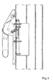
- the Figures 1 and 1a show an example, which is not an embodiment of the invention, but an example that facilitates the understanding of the invention.
- the Figures 1 and 1a show a section of a closing element 1 in the form of a panic door, which has a made of extruded aluminum profiles sash 2 with a filling of bulletproof glass and a frame, not shown, in which the sash 2 is rotatably mounted, wherein the frame in a building opening of a likewise not shown Building is anchored.
- actuating element 3 in the form of a Panikentriegelungs institutes in the form of a swivel bracket.
- the swivel bracket is at its two ends, each unwound at 45 ° (of which in FIG. 1 just one is shown) hinged to the sash 2.
- a bearing block 6 is attached for this purpose by means of screws 4 and a counter-plate 5.
- a not-shown, but known from the prior art actuating mechanism is set in motion, which acts on the nut of a lock 8 and also not shown locking elements extending from the sash in the frame inside extend, transferred to their unlocking position to swing in a panic case, the final element 1 from the locked, that is closed, state, that is, in this way to release an escape route out of the building.
- a holder 9 consisting of a flat steel is fastened to the bearing block 6 or the casement 2 with the aid of screws 10, one of which extends into the counterplate 5.
- a magnet 11 is attached at its free end with a screw.
- an adhesive element 12 in the form of a trapezoidal sheet is attached to the swivel bracket of the actuating element 3, which forms an adhesive surface 13 on its side facing the adhesive magnet 11.
- the holding magnet 11 is supplied with voltage via at least one of two feed lines, not shown, then the swivel bar is held on the holding magnet 11 via the holding element 12 such that the panic unlocking element is blocked in its basic position. It can therefore not be swung in the direction of arrow 7 on the closing element due to the very large adhesive force of unauthorized persons.
- the closing element 1 release an escape route
- the power supply to the holding magnet is completely interrupted, so that an actuation of the swivel bar, that is a pivoting in the direction of the arrow 7, is made possible again, whereby the locking elements of the closing element. 1 be disengaged.
- Restoration of the panic function may be either from a central office (eg after notification of a fire or other emergency in the building) or even by a person in need of an escape, for example by pressing a button or by detecting the person in an area be accomplished before the final element 1 using a motion detector.
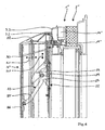
- a closure element 1 ' according to the Figures 2 and 3 Although also has a Panikentriegelungselement in the form of a swivel bracket as an actuating element 3.
- the blocking of the actuating element 3 takes place in this case, however, not by means of an adhesive magnet but by means of a standard component available as a swing door opener 14. This is in a by milling in the walls of the sash 2 'created interior of the sash 2' used and fixed there by means of screws.
- a pivotally mounted about an axis 15 on the bearing block 6 actuator 16 on the one hand has a receiving pin 17 for the tube designed as a swivel bracket and on the other hand connected to an actuating mechanism for unlocking the locking elements.
- the actuator 16 is still provided with a pressure piece 18 welded thereto, which cooperates with its free end with a latch 19 of the swing door opener 14 which is movably mounted in the direction of the double arrow 20 in the swing door opener 14 and by means of a spring in the direction of the swivel bar is biased.
- the pendulum door opener 14 is a known and tested or approved component, in which the case 19 by means of a magnet, not shown in the in FIG. 2 lock state shown is blocked, which in turn the Panikentriegelungselement in the form of the swivel bracket in the in FIG. 2 shown basic position is blocked.
- the swing door opener 14 which in turn is supplied with power via two supply lines, not shown, is disconnected from the power supply, then the latch 19 is free and the swivel bar can be pressed in the direction of the arrow 7 in order subsequently to open the in FIG. 3 represented occupy or emergency position, in which the locking elements of the closure element 1 'are in their unlocked position and thus the closure element 1' can be opened.
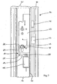
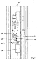
- FIGS. 4 and 5 show an even more alternative embodiment of the present invention a closing element 1 "also in the form of a panic door with a sash 2, wherein the actuating element 3" is listed in this case as a pressure bar, which is arranged in the direction of the double arrow 14 slidably in two end sides of the pressure bar and there with the wing frame 2 "connected bearing elements 22 is mounted.
- the pressure beam is provided on the one hand with a rocking lever 23, which is rotatably mounted on a bearing block 24 fixedly connected to the end element 1.
- a first arm 25 of the rocking lever 23 is pivotally mounted in a receiving element 26 of the pressure beam second arm 27 of the rocker arm 23, cooperates with a detail in detail not explained and consisting of a plurality of levers transmission mechanism 28, which is known from the prior art and ensures that upon actuation of the pressure bar, the latches of the closing element 1 "on a locknut unlocked.
- the second arm 27 also acts on an angular transmission element 30, which is displaceably mounted on the casement 2 "in the direction of the double arrow 31.
- the transmission element 30 has a blocking leg 32 which has an opening concealed in the bearing element 22 penetrates an outer sash profile 33 and abuts against a latch 19 "of a swing door opener 2", which is inserted through a cutout in the outer sash 33. In the swing door opener 14 "is powered and therefore blocked, neither the trap 19 "Still the transmission element 30 are moved, so that the pressure bar is locked in its normal position.
- FIG. 5 shows the emergency or operating position of the pressure bar, in which this by a distance 34 with respect to the in FIG. 4 shown basic position is shifted.
- the transmission element 30 is correspondingly displaced by the path 35 onto the swing door opener 14 "and has displaced the latch 19" into the swing door opener 14 ", since the actuating linkage 28 has likewise carried out its actuating movements during the displacement of the pressure bar unlocked and the final element 1 "can be opened.
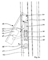
- FIGS. 6 . 6a and 6b show another example not belonging to the invention of a closing element 40, which is an actuating wing of a two-leaf door, which is mounted in a common frame 41.
- the door also includes a wing, which forms a second end element 42 in addition to the control wing.
- Both end elements 40 and 42 each have a sash 43 and 44 and an existing armored glass filling 45 and 46th
- the aerofoil has a conventional pusher 47 which acts on a concealed by a shield 48 lock which is actuated by means of a lock cylinder 49.
- the pusher 47 may be designed as Panikentriegelungselement, which would then create an escape route through the active leaf.
- the pusher can also be blocked as an actuator by means of a separate blocking device to improve the burglar resistance in this case.
- the control wing is provided with an actuating element 50 in the form of a pivotally mounted on the sash frame 43 handle. Pressed over the handle, not visible locking elements cause in their locking position an engagement between the sash frame 43 and the frame 41. If the handle in the in the FIG. 6 dashed position shown pivoted, the control wing is unlocked, so that the pedestrian wing, which is connected only via locking elements with the control wing, also becomes free. Both wings can thus after opening the Panikentriegelungselements in the form of the pivotable handle to the outside, that is in the direction of escape, be swung.
- the actuator 50 in the form of the handle is by means of a blocking device in the form of a pivotable stop, in the in FIG. 6a Blockable with a solid line shown basic position.
- the pivotable stop is formed by a folded and pivotable about an axis 51 mounted plate 52.
- the plate 52 has in cross-section parallel to the plane of the fillings 45 and 46 of the two wings extending support leg 53 and at an angle of 90 ° thereto extending stop leg 54.
- the latter serves to pivotal movement of the handle in the direction of arrow 55th to prevent what happens because the stop leg is within a pivoting range 56 of the handle.
- the slight possibility of movement of the handle up to a contact with the stop leg 54 does not allow unlocking of the locking elements of the control wing.
- the plate 52 is in the FIG. 6a blocked by solid lines drawn blocking position with the help of a held in a profile of the sash 43 magnet 43.
- the magnetic clamp 57 pulls the ferromagnetic material consisting of sheet metal 52 with great force to the sash 43, so that such a large frictional force arises that a pivoting movement of the sheet in the in FIG. 6a dashed position shown is suppressed. With the blocking of the plate 52 and thus the handle is blocked.
- the sheet 52 can be pivoted away in the direction of the arrow 58 upon actuation of the handle and thus the handle in the dashed position according to FIG. 6a be brought in which both the control wing and the pedestrian wings are aufdrückbar to the outside.
- the plate 52 is provided with two cutouts 59, the spacer plates 60, which are arranged below a bearing block 61 of the actuating element 50, to be omitted when the plate 52 in the in FIG. 6a represented by solid lines blocking position.
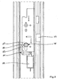
- FIGS. 7 and 8th show another not belonging to the invention example of a closure element 70 in the form of a door, comprising a sash 71 and a fixedly connected to the building frame 72.
- a lock 73 is installed in the sash and indeed in a cavity 74 of a sash profile 75.
- the known from the prior art lock 73 has a latch 76 and a latch 77 on.
- the latch 77 can be closed in a known manner with the aid of a lock cylinder 78.
- a shaft 79 of the lock cylinder 78 is provided in a known manner with a nose 80, which serves to drive an actuating mechanism for the latch 77.
- a blocking device for the actuating element in the form of the lock cylinder 78 comprises a pawl 81, which is mounted pivotally about an axis 82 in the sash profile 75.
- the pawl 81 has a in FIG. 7 on the nose 80 of the lock cylinder 78 supporting the blocking arm 83 and a right angle thereto arranged drive arm 84 which is pivotally coupled to a push rod 85 of an electromagnet 86.
- the pawl 81 is in the in FIG. 7 locked state shown. If the power supply to the solenoid 86 is interrupted, the armature and thus also the push rod 85 of the electromagnet by spring bias in the in FIG. 8 shown transferred upper position, which is why the pawl 81, the in FIG. 8 shown release position occupies.
- the blocking arm 83 of the pawl 81 is pivoted out of the marked by a line 87 rotation of the nose 80 in this state, so that the lock cylinder 78 and thus the latch 77 is normally actuated.
- FIGS. 7 and 8th very similar.
Landscapes
- Physics & Mathematics (AREA)
- Electromagnetism (AREA)
- Business, Economics & Management (AREA)
- Emergency Management (AREA)
- Power-Operated Mechanisms For Wings (AREA)
- Building Environments (AREA)
- Glass Compositions (AREA)
- Closing And Opening Devices For Wings, And Checks For Wings (AREA)
Description
- Die Erfindung betrifft ein Gebäude mit mindestens einer Gebäudeöffnung und einem an dem Gebäude um mindestens eine Drehachse drehbar in der Gebäudeöffnung gelagerten Abschlusselement, das in einer Schließstellung die Gebäudeöffnung verschließt und in einer Öffnungsstellung einen Durchtritt einer Person durch die Gebäudeöffnung erlaubt, wobei das Abschlusselement in der Schließstellung mittels Verriegelungselementen gegen eine unbefugte Öffnung verriegelbar ist und die Verriegelungselemente mittels eines Betätigungselements von einer Verriegelungsstellung in eine Entriegelungsstellung, in der das Abschlusselement in die Öffnungsstellung drehbar ist, überführbar sind, indem das Betätigungselement von einer Grundstellung, in der sich die Verrieglungselemente in der Verriegelungsstellung befinden, in eine Betätigungsstellung überführt wird, in der die Verriegelungselemente in die Entriegelungsstellung übergehen, wobei das Betätigungselement mittels einer Blockiereinrichtung in der Grundstellung blockierbar ist und die Blockiereinrichtung von einem Sperrzustand, in dem das Betätigungselement blockiert ist, dadurch in einen Freigabezustand überführbar ist, dass eine Auslöseeinrichtung ein Auslösesignal abgibt.
- Unter einem Abschlusselement im Sinne der vorliegenden Anmeldung können alle drehbeweglich gelagerten Verschlussorgane verstanden werden, wobei es sich in häufigen Fällen um Fenster, Türen, Klappen o.ä. handelt. Die Abschlusselemente können plattenförmig ausgebildet sein oder einen beweglichen Flügelrahmen besitzen, in den eine Füllung aus Glas, Kunststoff oder Metall eingesetzt ist. An einer Laibung der Gebäudeöffnung kann ein Blendrahmen
- befestigt sein, in dem wiederum der Flügelrahmen gelagert ist. Innerhalb einer Gebäudeöffnung können mehrere Abschlusselemente gelagert sein, die sich beide in Ihrer Schließstellung befinden müssen, um die Gebäudeöffnung wirksam zu verschließen.
- Bei dem Betätigungselement kann es sich um alle Elemente handeln, die von dem hierzu legitimierten Benutzern bedient werden und bestimmungsgemäß dazu vorgesehen sind, unmittelbar oder mittelbar über zwischengeschaltete Übertragungselemente auf die Verriegelungselemente einzuwirken und diese von ihrer Verriegelungsstellung in die Entriegelungsstellung und umgekehrt zu überführen.
- Zur Absicherung eines Gebäudes gegen Einbruch, Aufbruch oder Ausbruch werden die diesbezüglich besonders gefährdeten Abschlusselemente typischerweise in einer besonders massiven und widerstandsfähigen Bauweise ausgeführt. Dies betrifft sowohl das Abschlusselement und die daran vorhandenen Rahmen (Blend-oder Flügelrahmen), als auch die Verriegelungselemente und die damit korrespondierenden Betätigungselemente. Insbesondere bei den Betätigungselementen besteht die Gefahr, dass diese unbefugt betätigt werden, was dadurch geschehen kann, dass innenliegende Betätigungselemente bei einem Einbruchversuch von Außen durch eine in das Abschlusselement gewaltsam eingebrachte Öffnung hindurch betätigt werden, wodurch das Abschlusselement anschließend gänzlich in die Öffnungsstellung überführt werden kann. Alternativ besteht eine Vorgehensweise bei einem Einbruchversuch auch darin, von außen zugängliche Betätigungselemente, wie zum Beispiel Schließzylinder, gewaltsam zu zerstören oder so zu manipulieren, dass die Verriegelungselemente in die Entriegelungsstellung überführt werden können.
- Aus der
DE 20 2007 015 667 U1 ist es bekannt, im Falle einer Detektion eines Einbruchversuchs zusätzliche Verriegelungselemente zu aktivieren, das heißt insbesondere in Eingriff zu bringen, so dass die Sicherheit gegen Aufbruch des Abschlusselementes erhöht wird. Eine derartige Vorgehensweise ist insbesondere bei sogenannten Paniktüren vorteilhaft, die mit Panikentriegelungselementen versehen sind, die auf der Innenseite des Abschlusselements an exponierter Stelle angeordnet und aus Sicherheitsgründen sehr großvolumig und gut betätigbar ausgeführt sind. Derartige Panikentriegelungselemente provozieren die Gefahr, dass nach der Zerstörung beispielsweise einer Glasfüllung das Panikentriegelungselement von einem Einbrecher unbefugt von außen betätigt und somit die Tür geöffnet wird. Gemäß derDE 20 2007 015 667 U1 wird die Sicherheit dadurch erhöht, dass im Falle der Detektion eines Einbruchversuchs, beispielsweise durch Zerstören einer Alarmspinne oder auch einer Detektion des Einbrechers mittels eines Bewegungsmelders, zusätzliche Verriegelungselemente aktiviert werden, so dass selbst bei Betätigung des Panikentriegelungselements die Tür nicht öffnet. - Es besteht hier die Gefahr, dass ein Einbruchversuch nicht zuverlässig detektiert wird und somit die Aktivierung der Zusatzverriegelungselemente unterbleibt. Des Weiteren können Probleme dadurch entstehen, dass nach Aktivierung der zusätzlichen an der Schlossmechanik angreifenden Verriegelungselemente die Schlossmechanik beschädigt wird, wenn bei einem Einbruchversuch große Kräfte auf das Betätigungselement aufgebracht werden. Dies kann dazu führen, dass nach einem solchen Einbruchversuch die Schlossmechanik nicht mehr funktionsfähig ist, so dass z.B. eine Panikfunktion nicht mehr gegeben ist. Auch könnte ein Einbrecher bewusst versuchen, die Detektionseinrichtungen zu manipulieren oder zu zerstören, um eine Aktivierung der zusätzlichen Verriegelungselemente zu verhindern.
- Das Dokument
US 4 627 649 offenbart ein Gebäude gemäß dem Oberbegriff des Anspruchs 1. - Der Erfindung liegt die Aufgabe zugrunde, ein Gebäude mit erhöhter Sicherheit gegenüber Einbruch, Aufbruch oder Ausbruch zu schaffen, dass sich einerseits durch eine hohe Sicherheit und andererseits durch einen möglichst geringen Herstell- und Bauaufwand auszeichnet.
- Ausgehend von einem Gebäude der eingangs beschriebenen Art, wird diese Aufgabe erfindungsgemäß dadurch gelöst, dass die Blockiereinrichtung mindestens einen Pendeltüröffner aufweist, der an oder in einem Flügelrahmenprofil verdeckt angeordnet ist, wobei ein mit dem Betätigungselement gekoppeltes Übertragungselement durch die Falle des Pendeltüröffners blockierbar ist.
- Erfindungsgemäß wird ein Pendeltüröffner verwendet, der an oder in einem Flügelrahmenprofil vorzugsweise auf einer einem Schloss des Abschlusselements gegenüberliegenden Seite des Flügelrahmens verdeckt angeordnet ist, wobei ein mit dem Betätigungselement, vorzugsweise mit dem Druckbalken oder dem Schwenkbügel gekoppeltes Übertragungselement durch die Falle des Pendeltüröffners blockierbar ist. Derartige Pendeltüröffner stellen standardmäßig verfügbare und sicherheitstechnisch geprüfte Bauteile dar. Die Falle des Pendeltüröffners ist federbelastet und ist in ihrer Grundstellung ausgefahren. Elektromagnetisch wird die Falle in dieser Grundstellung blockiert, wobei Haltekräfte von ca. 500 kg aufgenommen werden können. Hieraus lassen sich hinreichend große Blockierkräfte für das Betätigungselement erzielen.
- Das Dokument
FR 2 865 491 - Das Betätigungselement wird blockiert, um eine unbefugte Betätigung des selben zu vermeiden. Dabei wird der Bedienungskomfort dadurch erhöht, dass die Überführung der Blockiereinrichtung von deren Sperrzustand in deren Freigabezustand auf ferngesteuerte Weise mit Hilfe einer Auslöseeinrichtung möglich wird, die in einer gewissen Entfernung von der Blockiereinrichtung und auch von dem Abschlusselement selbst angeordnet sein kann und bei Aktivierung ein Auslösesignal abgibt, um die Blockade des Betätigungselements aus der Ferne aufzuheben. In einem nach der Erfindung als Normalzustand zu definierenden Zustand ist somit das Betätigungselement nicht freigegeben, sondern die Aufhebung der Blockierung wird erst und nur dann ausgeführt, wenn von einer befugten Person tatsächlich der Wunsch besteht, die Verriegelungselemente in ihre Entriegelungsstellung zu überführen, um das Abschlusselement sodann in die Öffnungsstellung zu bringen. Dieser Wunsch kann von der Auslöseeinrichtung automatisiert detektiert werden oder manuell mittels eines entsprechendes Auslöseelements geäußert werden.
- Es besteht natürlich die Möglichkeit die Blockiereinrichtung beispielsweise nur während bestimmter Zeiten, so zum Beispiel der Nachtstunden, in ihrem Sperrzustand als Normalzustand zu halten. In dieser Zeit sind befugte Benutzungen des Abschlusselements ausgeschlossen, bzw. so selten, dass die Notwendigkeit, zuvor über die Auslöseeinrichtung ein Auslösesignal zur Überführung der Blockiereinrichtung in den Freigabezustand abgeben zu müssen, keine wirkliche Behinderung in der Praxis darstellt. Hingegen kann zu anderen Zeiten, insbesondere tagsüber, die Blockiereinrichtung normalerweise in dem Freigabezustand sein, um bei häufigen Nutzungen des Gebäudeabschlusses den Komfort zu erhöhen, so dass dann das Betätigungselement auch ohne vorherige Aktivierung der Auslöseeinrichtung benutzbar ist. Die für die Nachtstunden in diesen Fällen ohnehin vorhandene Blockiereinrichtung kann während der Tagesstunden auch dazu benutzt werden, im Falle der Detektion eines Einbruchversuchs die Blockiereinrichtung in ihren Sperrzustand zu überführen. Insofern wird die Blockiereinrichtung in diesem Falle als zusätzliches Verriegelungselement genutzt, was der Lehre der
DE 20 2007 015 667 U1 entspricht. - Vorzugsweise greift die Blockiereinrichtung an dem Betätigungselement selbst bzw. - in Kraftfluss von der Hand des Benutzers bis hin zu den Verriegelungselementen betrachtet"vor" dem Betätigungselement an. Jedenfalls sollte vermieden werden, im Kraftfluss weiter "hinten" liegende Elemente eines Übertragungsmechanismus in Form von Hebeln, Gestängen, Getrieben oder dergleichen, zu blockieren, da dann die Gefahr besteht, dass die der Blockierstelle vorgeschalteten Elementes des Übertragungsmechanismus durch rohe Gewaltanwendung beschädigt, insbesondere verbogen oder verklemmt werden (ohne die Blockierstelle zu überwinden, das heißt ohne das Abschlusselement öffnen zu können). Eine derartige Beschädigung würde das Funktionieren des Übertragungsmechanismus in Frage stellen oder aufheben, so dass die Paniköffnungsfunktion einer Paniktür nicht mehr gewährleistet wäre.

- In sehr vorteilhafterweise lässt sich die vorliegende Erfindung bei Paniktüren anwenden. Das Betätigungselement ist in diesem Fall als Panikentriegelungselement ausgeführt und auf eine einen Innenraum eines Gebäudes zugewandten Seite des Abschlusselements angeordnet. Die im Panikfall eingenommene Betätigungsstellung kann in diesem Fall als Notstellung bezeichnet werden.
- Die Auslöseeinrichtung kann einen in einem Abstand von dem Abschlusselement angeordneten Auslösetaster, Auslöseschalter (der auch in einer Alarm- oder Überwachungszentrale angeordnet sein kann) der von einer in dem Innenraum befindlichen Person betätigbar ist oder Auslösesensor aufweisen, der eine dort befindliche Person erkennt und das Auslösesignal automatisch abgibt. Die Blockiereinrichtung umfasst vorzugsweise einen Elektromagneten, der mittels der Auslöseeinrichtung stromlos schaltbar ist. Die Blockierung des Betätigungselements ist somit nur möglich, wenn die Spule des Elektromagneten mit Strom beaufschlagt ist. Sollte in einem Notfall der Strom ausfallen, so begibt sich die Blockiereinrichtung, die zu diesem Zweck mit einem entsprechenden Federelement ausgestattet ist, automatisch in den Freigabezustand, so dass das Abschlusselement nach Betätigung des Betätigungselementes öffenbar ist.
- Bei dem Panikentriegelungselement kann es sich um einen um eine horizontale Achse schwenkbar gelagerten und an beiden Enden jeweils an einem Flügelrahmenprofil gelenkig befestigten Schwenkbügel handeln. Alternativ kommt auch ein horizontal verlaufender, in eine Richtung senkrecht zu der Ebene des Abschlusselements relativ zu diesem verschiebbarer und an beiden Enden jeweils an einem Flügelrahmenprofil befestigter Druckbalken in Frage.
- Konkret kann die Blockierung eines Panik-Druckbalkens mittels eines winkelförmigen Übertragungselements erfolgen, dass von einem Betätigungsgestänge des Druckbalkens in horizontale Richtung verschiebbar ist und mit einem Blockierschenkel eine verdeckte Öffnung in dem Flügelrahmenprofil durchdringt und an der Falle des Pendeltüröffners anliegt. Die verdeckte Öffnung für den Blockierschenkel erlaubt es einem Angreifer nicht, die Funktionsweise und genaue Anordnung der Blockiereinrichtung zu erkennen, so dass die Sicherheit entsprechend groß ist.
- Ferner wird gemäß der Erfindung noch vorgeschlagen, zwei getrennte Zuleitungen zu dem Elektromagneten zu führen, wobei die Zuleitungen sich an der Blockiereinrichtung trennen in einem räumlichen Abstand zueinander verlaufen und erst unmittelbar vor der Auslöseeinrichtung wieder zusammengeführt sind. Sollte es einem Einbrecher gelingen eine der beiden Zuleitungen zu zerstören, insbesondere zu durchtrennen, so würde er hierdurch dennoch nicht erreichen, den Elektromagneten stromlos zu schalten und somit den Freigabezustand der Blockiereinrichtung zu erhalten, da in diesem Fall mindestens noch eine weitere Zuleitung die Spannungsversorgung des Elektromagneten sicher stellt.
- Die Erfindung wird nachfolgend anhand mehrerer Ausführungsbeispiele, die in der beiliegenden Zeichnung dargestellt sind, näher erläutert.
- Es zeigt:
- Figur 1
- eine Vorderansicht eines Teils einer Paniktür mit einem Panikentriegelungselement in Form eines Schwenkbügels und mit einer einen nicht zur Erfindung gehörenden Haft- magneten umfassenden Blockiereinrichtung,
- Figur 1a
- wie
Figur 1 , jedoch in einer Seitenansicht, - Figur 2
- wie
Figur 1a , jedoch mit einer erfindungsgemäßen einen Pendeltüröffner umfassenden Blo- ckiereinrichtung in der Grundstellung des Betätigungselementes, - Figur 3
- wie
Figur 2 , jedoch in der Betätigungs- bzw. Notstellung des Betäti- gungselementes, - Figur 4
- einen Horizontalschnitt durch ein Betätigungselement in Form eines Druckbalkens mit einer erfindungsgemäßen einen Pendeltüröffner umfassenden Blockier- einrichtung in der Grundstellung des Betätigungselementes,
- Figur 5
- wie
Figur 4 , jedoch in der Betätigungs- bzw. Notstellung des Betäti- gungselementes, - Figur 6
- eine Vorderansicht eines nicht zur Erfindung gehörenden Betätigungselementes in Form eines Griffs ei- nes Stellflügels einer zweiflügeligen Tür,
- Figur 6a
- eine vergrößerte Darstellung eines Ausschnitts aus
Figur 6 , - Figur 6b
- einen Schnitt durch das Betätigungselement und die Blockiereinrich- tung gemäß der
Figuren 6 und6a , - Figur 7
- eine Ansicht einer nicht zur Erfindung gehörenden Blockiereinrichtung für eine Nase einer Welle eines Schließzylinders in dem Sperrzustand der Blockiereinrichtung,
- Figur 8
- wie
Figur 7 , jedoch in dem Freigabezustand der Blockiereinrichtung, - Figur 9
- wie
Figur 7 , jedoch mit einer Blockierung eines Zahnrades einer Welle eines Schlosses in dem Sperrzustand der Blockiereinrichtung - Figur 10
- wie
Figur 9 , jedoch in dem Freigabezustand der Blockiereinrichtung. - Die
Figuren 1 und 1a zeigen ein Beispiel, wobei es sich nicht um ein Ausführungsbeispiel der Erfindung handelt, sondern um ein Beispiel, das das Verständnis der Erfindung erleichtert. DieFiguren 1 und 1a zeigen einen Ausschnitt eines Abschlusselementes 1 in Form einer Paniktür, die einen aus Aluminiumstrangpressprofilen hergestellten Flügelrahmen 2 mit einer Füllung aus einem Panzerglas und einen nicht dargestellten Blendrahmen besitzt, in dem der Flügelrahmen 2 drehbar gelagert ist, wobei der Blendrahmen in einer Gebäudeöffnung eines ebenfalls nicht dargestellten Gebäudes verankert ist. - Da es sich um eine Paniktür handelt, ist diese mit einem Betätigungselement 3 in Form eines Panikentriegelungselementes in Form eines Schwenkbügels ausgeführt. Der Schwenkbügel ist an seinen beiden, jeweils zweimal um 45° abgewickelten Enden (von denen in
Figur 1 nur eines dargestellt ist) an den Flügelrahmen 2 angelenkt. An dem Flügelrahmen 2 ist zu diesem Zweck mittels Schrauben 4 und einer Gegenplatte 5 ein Lagerbock 6 befestigt. Bei Verschwenkung des Betätigungselementes 3 in Richtung des Pfeils 7 wird eine nicht dargestellte, aber aus dem Stand der Technik bekannte Betätigungsmechanik in Gang gesetzt, die auf die Nuss eines Schlosses 8 einwirkt und gleichfalls nicht dargestellte Verriegelungselemente, die sich aus dem Flügelrahmen in den Blendrahmen hinein erstrecken, in deren Entriegelungsstellung überführt, um in einem Panikfall das Abschlusselement 1 auch aus dem verriegelten, das heißt verschlossenen, Zustand aufschwenken zu können, das heißt auf diese Weise einen Fluchtweg aus dem Gebäude heraus freizugeben. - Erfindungsgemäß ist an dem Lagerbock 6 bzw. dem Flügelrahmen 2 ein aus einem Flachstahl bestehender Halter 9 mit Hilfe von Schrauben 10 befestigt, von denen sich eine bis in die Gegenplatte 5 erstreckt. An dem Halter 9 ist an seinem freien Ende mit einer Schraube ein Haftmagnet 11 befestigt.
- An einer dem freien Ende des Halters 9 gegenüberliegenden Seite ist an dem Schwenkbügel des Betätigungselements 3 ein Haftelement 12 in Form eines trapezförmigen Bleches befestigt, das auf seiner dem Haftmagneten 11 zugewandten Seite eine Haftfläche 13 ausbildet.
- Ist der Haftmagnet 11 über mindestens eine von zwei nicht dargestellten Zuleitungen mit Spannung versorgt, so wird der Schwenkbügel über das Haftelement 12 derart an dem Haftmagneten 11 gehalten, dass das Panikentriegelungselement in seiner Grundstellung blockiert ist. Es kann somit aufgrund der sehr großen Haftkraft von unbefugten Personen nicht in Richtung des Pfeils 7 auf das Abschlusselement zugeschwenkt werden.
- Soll ausgehend von diesem blockierten Zustand das Abschlusselement 1 einen Fluchtweg freigeben, so wird die Stromzufuhr zu dem Haftmagneten vollständig unterbrochen, so dass eine Betätigung des Schwenkbügels, das heißt eine Verschwenkung in Richtrung des Pfeils 7, wieder ermöglicht wird, wodurch die Verriegelungselemente des Abschlusselementes 1 außer Eingriff gebracht werden. Die Wiederherstellung der Panikfunktion kann entweder von einer Zentrale aus (z. B. nach Meldung eines Brand- oder sonstigen Notfalls in dem Gebäude) oder aber auch von einer fluchtwilligen Person selbst, beispielsweise durch Drücken auf einen Taster oder durch Detektion der Person in einem Bereich vor dem Abschlusselement 1 mit Hilfe eines Bewegungsmelders bewerkstelligt werden.
- Die erfindungsgemäße Ausführungsform eines Abschlusselementes 1' gemäß den
Figuren 2 und3 weist zwar auch ein Panikentriegelungselement in Form eines Schwenkbügels als Betätigungselement 3 auf. Die Blockierung des Betätigungselementes 3 erfolgt in diesem Fall jedoch nicht mittels eines Haftmagneten sondern mittels eines als Standardbauteil verfügbaren Pendeltüröffners 14. Dieser ist in einen durch Ausfräsungen in den Wänden des Flügelrahmens 2' geschaffenen Innenraum des Flügelrahmens 2' eingesetzt und dort mittels Schrauben fixiert. Ein um eine Achse 15 schwenkbar an dem Lagerbock 6 befestigtes Betätigungsglied 16 besitzt einerseits einen Aufnahmezapfen 17 für den als Rohr ausgeführten Schwenkbügel und ist andererseits an einen Betätigungsmechanismus zur Entriegelung der Verriegelungselemente angeschlossen. - Erfindungsgemäß ist das Betätigungsglied 16 noch mit einem daran angeschweißten Druckstück 18 versehen, das mit seinem freien Ende mit einer Falle 19 des Pendeltüröffners 14 zusammenwirkt, die in Richtung des Doppelpfeils 20 beweglich in dem Pendeltüröffner 14 gelagert ist und mittels einer Feder in Richtung auf den Schwenkbügel vorgespannt ist. Bei dem Pendeltüröffner 14 handelt es sich um ein bekanntes und geprüftes bzw. zugelassenes Bauteil, bei dem die Falle 19 mittels eines nicht dargestellten Magneten in den in
Figur 2 dargestellten Sperrzustand blockierbar ist, wodurch wiederum das Panikentriegelungselement in Form des Schwenkbügels in der inFigur 2 gezeigten Grundstellung blockiert ist. - Wird der Pendeltüröffner 14 der wiederum über zwei nicht dargestellte Zuleitungen mit Strom versorgt ist, von der Stromversorgung getrennt, so ist die Falle 19 frei und der Schwenkbügel kann in Richtung des Pfeils 7 gedrückt werden, um anschließend die in
Figur 3 dargestellte Betätigungs- bzw. Notstellung einzunehmen, in der die Verriegelungselemente des Abschlusselementes 1' sich in ihrer Entriegelungsstellung befinden und somit das Abschlusselement 1' öffenbar ist. - Die
Figuren 4 und5 zeigen eine nochmals alternative erfindungsgemäße Ausführungsform eines Abschlusselements 1" gleichfalls in Form einer Paniktür mit einem Flügelrahmen 2", wobei das Betätigungselement 3" in diesem Fall als Druckbalken aufgeführt ist, der in Richtung des Doppelpfeils 14 verschiebbar in zwei endseitig des Druckbalkens angeordnet und dort mit dem Flügelrahmen 2 " verbundenen Lagerelementen 22 gelagert ist. - Der Druckbalken ist zum einen mit einem Schwinghebel 23 versehen, der an einem fest mit dem Abschlusselement 1" verbundenen Lagerbock 24 drehbar gelagert ist. Ein erster Arm 25 des Schwinghebels 23 ist in einem Aufnahmeglied 26 des Druckbalkens schwenkbar gelagert. Der an dem gegenüberliegenden Ende befindliche zweite Arm 27 des Schwinghebels 23, wirkt mit einer im Detail nicht näher erläuterten und aus einer Mehrzahl von Hebeln bestehenden Übertragungsmechanik 28 zusammen, die aus dem Stand der Technik bekannt ist und dafür sorgt, dass bei Betätigung des Druckbalkens die Verriegelungen des Abschlusselementes 1" über eine Schlossnuss entriegelt werden.
- Über ein Zwischenstück 29 wirkt der zweite Arm 27 aber auch auf ein winkelförmiges Übertragungselement 30, das in Richtung des Doppelpfeils 31 verschiebbar an dem Flügelrahmen 2" gelagert ist. Das Übertragungselement 30 weist einen Blockierschenkel 32 auf, der eine von dem Lagerelement 22 verdeckte Öffnung in einem äußeren Flügelrahmenprofil 33 durchdringt und an einer Falle 19" eines Pendeltüröffners 2" anliegt, der durch eine Ausfräsung in dem äußeren Flügelrahmenprofil 33 hindurch in dessen Innenraum eingesetzt ist. Ist der Pendeltüröffner 14" mit Strom versorgt und daher blockiert, kann weder die Falle 19" noch das Übertragungselement 30 bewegt werden, so dass der Druckbalken in seiner Grundstellung arretiert ist.
-
Figur 5 zeigt die Not- bzw. Betätigungsstellung des Druckbalkens, in der dieser um einen Weg 34 gegenüber der inFigur 4 dargestellten Grundstellung verschoben ist. Das Übertragungselement 30 ist entsprechend um den Weg 35 auf den Pendeltüröffner 14" zu verschoben und hat die Falle 19" in den Pendeltüröffner 14" hinein verschoben. Da das Betätigungsgestänge 28 im Zuge der Verschiebung des Druckbalkens gleichfalls seine Stellbewegungen ausgeführt hat, ist auch das Schloss entriegelt und das Abschlusselement 1" kann geöffnet werden. - Die
Figuren 6 ,6a und6b zeigen ein weiteres nicht zur Erfindung gehörendes Beispiel eines Abschlusselements 40, bei dem es sich um einen Stellflügel einer zweiflügeligen Tür handelt, die in einem gemeinsamen Blendrahmen 41 gelagert ist. Die Tür umfasst neben dem Stellflügel noch einen Gehflügel, der ein zweites Abschlusselement 42 bildet. Beide Abschlusselemente 40 und 42 besitzen jeweils einen Flügelrahmen 43 und 44 sowie eine aus Panzerglas bestehende Füllung 45 und 46. - Der Gehflügel besitzt einen herkömmlichen Drücker 47, der auf ein durch ein Schild 48 verdecktes Schloss wirkt, das mittels eines Schließzylinders 49 betätigbar ist. Alternativ kann der Drücker 47 auch als Panikentriegelungselement ausgeführt sein, wodurch dann eine Fluchtmöglichkeit durch den Gangflügel geschaffen würde. Der Drücker kann auch als Betätigungselement mittels einer eigenen Blockiereinrichtung blockiert werden, um die Einbruchhemmung in diesem Fall zu verbessern.
- Der Stellflügel ist mit einem Betätigungselement 50 in Form eines schwenkbar an dem Flügelrahmen 43 gelagerten Griffs versehen. Über den Griff betätigte, nicht sichtbare Verriegelungselemente bewirken in deren Verriegelungsstellung einen Eingriff zwischen dem Flügelrahmen 43 und dem Blendrahmen 41. Wird der Griff in die in der
Figur 6 gestrichelt dargestellte Position verschwenkt, so wird der Stellflügel entriegelt, so dass der Gehflügel, der lediglich über Verriegelungselemente mit dem Stellflügel verbunden ist, gleichfalls freigängig wird. Beide Flügel können somit nach Betätigen des Panikentriegelungselements in Form des schwenkbaren Griffs nach außen, das heißt in Fluchtrichtung, aufgeschwenkt werden. - Das Betätigungselement 50 in Form des Griffs ist mittels einer Blockiereinrichtung in Form eines schwenkbaren Anschlags, in der in
Figur 6a mit durchgezogener Linie gezeigten Grundposition blockierbar. Der verschwenkbare Anschlag wird gebildet von einem abgekanteten und um eine Achse 51 schwenkbar gelagerten Blech 52. Wie sich ausFigur 6b ergibt, besitzt das Blech 52 im Querschnitt einen parallel zu der Ebene der Füllungen 45 und 46 der beiden Flügel verlaufenden Stützschenkel 53 sowie einen unter einem Winkel von 90° hierzu verlaufenden Anschlagschenkel 54. Letzterer dient dazu, eine Schwenkbewegung des Griffs in Richtung des Pfeils 55 zu unterbinden, was deshalb geschieht, weil der Anschlagschenkel sich innerhalb eines Schwenkbereichs 56 des Griffs befindet. Die geringfügige Bewegungsmöglichkeit des Griffs bis zu einem Kontakt mit dem Anschlagschenkel 54 ermöglicht nicht ein Entriegeln der Verriegelungselemente des Stellflügels. - Das Blech 52 wird in der
Figur 6a in durchgezognen Linien gezeichneten Blockierstellung mit Hilfe eines in einem Profil des Flügelrahmens 43 gehaltenen Haftmagnets 57 blockiert. Der Haftmagnet 57 zieht das aus ferromagnetischem Material bestehende Blech 52 mit großer Kraft an den Flügelrahmen 43, so dass eine derart große Reibkraft entsteht, dass eine Schwenkbewegung des Blechs in die inFigur 6a gestrichelt dargestellte Position unterbunden wird. Mit der Blockierung des Blechs 52 ist somit auch der Griff blockiert. - Ist der Haftmagnet 57 stromlos, kann das Blech 52 bei Betätigung des Griffs in Richtung des Pfeils 58 weggeschwenkt und somit der Griff in die gestrichelte Position gemäß
Figur 6a gebracht werden, in der sowohl der Stellflügel als auch der Gehflügel nach außen aufdrückbar sind. - Das Blech 52 ist mit zwei Ausschnitten 59 versehen, die Distanzplatten 60, die unterhalb eines Lagerbocks 61 des Betätigungselementes 50 angeordnet sind, aussparen, wenn sich das Blech 52 in der in
Figur 6a durchgezogenen Linien dargestellten Blockierstellung befindet. - Die
Figuren 7 und8 zeigen ein weiteres nicht zur Erfindung gehörendes Beispiel eines Abschlusselementes 70 in Form einer Tür, umfassend einen Flügelrahmen 71 und einen mit dem Gebäude fest verbundenen Blendrahmen 72. In einem Falzbereich zwischen Flügelrahmen 71 und Blendrahmen 72 ist ein Schloss 73 in den Flügelrahmen eingebaut und zwar in einen Hohlraum 74 eines Flügelrahmenprofils 75. Das aus dem Stand der Technik bekannte Schloss 73 weist eine Falle 76 sowie einen Riegel 77 auf. Der Riegel 77 ist auf bekannte Weise mit Hilfe eines Schließzylinders 78 schließbar. Eine Welle 79 des Schließzylinders 78 ist in bekannter Weise mit einer Nase 80 versehen, die zum Antrieb einer Betätigungsmechanik für den Riegel 77 dient. - Eine Blockiereinrichtung für das Betätigungselement in Form des Schließzylinders 78 umfasst eine Sperrklinke 81, die um eine Achse 82 gelenkig in dem Flügelrahmenprofil 75 gelagert ist Die Sperrklinke 81 besitzt einen sich in
Figur 7 an der Nase 80 des Schließzylinders 78 abstützenden Blockierarm 83 und einen im rechten Winkel hierzu angeordneten Antriebsarm 84, der gelenkig mit einer Schubstange 85 eines Elektromagneten 86 gekoppelt ist. - Ist der Magnet 86 mit Strom versorgt und der mit der Schubstange 85 verbundene Anker in der nach unten angezogenen Stellung, befindet sich die Sperrklinke 81 in dem in
Figur 7 gezeigten Sperrzustand. Wird die Stromversorgung zu dem Elektromagneten 86 unterbrochen, so wird der Anker und somit auch die Schubstange 85 des Elektromagneten durch Federvorspannung in die inFigur 8 dargestellte obere Position überführt, weshalb die Sperrklinke 81 die inFigur 8 dargestellte Freigabestellung einnimmt. Der Blockierarm 83 der Sperrklinke 81 ist in diesem Zustand aus dem durch eine Linie 87 markierten Drehbereich der Nase 80 herausgeschwenkt, so dass der Schließzylinder 78 und damit der Riegel 77 normal betätigbar ist. - Die Funktionsweise der nicht zur Erfindung gehörenden Blockiereinrichtung des Abschlusselementes 70' gemäß den
Figuren 9 und10 ist der derFiguren 7 und8 sehr ähnlich. Die Sperrklinke 81' blockiert in diesem Fall nicht die gleichfalls vorhandene Nase 80 an der Welle 79 des Schließzylinders 78'. Vielmehr greift die Sperrklinke 81' mit einer am Ende des Blockierarms 83' vorhandenen Verzahnung in ein axial neben der Nase 80 auf der Welle 79 des Schlosses 73 angeordnetes Zahnrad 88 ein. WährendFigur 9 den Sperrzustand der Sperrklinke 81' zeigt, veranschaulichtFigur 10 den Freigabezustand, in dem der Elektromagnet 86 stromlos ist und die Verzahnungen des Blockierarms 83' der Sperrklinke 81' und des Zahnrades 88 des Schlosses 73 somit außer Eingriff sind. Der Schließzylinder 78' lässt sich damit drehen und kann ein nicht dargestelltes, mit dem Zahnrad 88 in Eingriff stehendes Ritzel des Schlosses 73 betätigen, das wiederum zu einer Verschiebung des Riegels 77 führt. -
- 1, 1', 1"
- Abschlusselement
- 2, 2', 2"'
- Flügelrahmen
- 3, 3"
- Betätigungselement
- 4
- Schraube
- 5
- Gegenplatte
- 6
- Lagerbock
- 7
- Pfeil
- 8
- Schloss
- 9
- Halter
- 10
- Schraube
- 11
- Haftmagnet
- 12
- Haftelement
- 13
- Haftfläche
- 14, 14"
- Pendeltüröffner
- 15
- Achse
- 16
- Betätigungsglied
- 17
- Aufnahmezapfen
- 18
- Druckstück
- 19, 19"
- Falle
- 20
- Doppelpfeil
- 21
- Doppelpfeil
- 22
- Lagerelement
- 23
- Schwinghebel
- 24
- Lagerbock
- 25
- Arm
- 26
- Aufnahmeglied
- 27
- Arm
- 28
- Betätigungsgestänge
- 29
- Zwischenstück
- 30
- Übertragungselement
- 31
- Doppelpfeil
- 32
- Blockierschenkel
- 33
- Flügelrahmenprofil
- 34
- Weg
- 35
- Weg
- 40
- Abschlusselement
- 41
- Blendrahmen
- 42
- Abschlusselement
- 43
- Flügelrahmen
- 44
- Flügelrahmen
- 45
- Füllung
- 46
- Füllung
- 47
- Drücker
- 48
- Schild
- 49
- Schließzylinder
- 50
- Betätigungselement
- 51
- Achse
- 52
- Blech
- 53
- Stützschenkel
- 54
- Anschlagschenkel
- 55
- Pfeil
- 56
- Schwenkbereich
- 57
- Haftmagnet
- 58
- Pfeil
- 59
- Ausschnitt
- 60
- Distanzplatte
- 61
- Lagerbock
- 70, 70'
- Abschlusselement
- 71
- Flügelrahmen
- 72
- Blendrahmen
- 73
- Schloss
- 74
- Hohlraum
- 75
- Flügelrahmenprofil
- 76
- Falle
- 77
- Riegel
- 78, 78'
- Schließzylinder
- 79
- Welle
- 80
- Nase
- 81, 81'
- Sperrklinke
- 82
- Achse
- 83, 83'
- Blockierarm
- 84
- Antriebsarm
- 85
- Schubstange
- 86
- Elektromagnet
- 87
- Linie
- 88
- Zahnrad
Claims (7)
- Gebäude mit mindestens einer Gebäudeöffnung und einem an dem Gebäude um mindestens eine Drehachse drehbar in der Gebäudeöffnung gelagerten Abschlusselement (1', 1") das in einer Schließstellung die Gebäudeöffnung verschließt und in einer Öffnungsstellung einen Durchtritt einer Person durch die Gebäudeöffnung erlaubt, wobei das Abschlusselement (1', 1") in der Schließstellung mittels Verriegelungselementen gegen eine unbefugte Öffnung verriegelbar ist und die Verriegelungselemente mittels eines Betätigungselements (3, 3"), von einer Verriegelungsstellung in eine Entriegelungsstellung, in der das Abschlusselement (1', 1") in die Öffnungsstellung drehbar ist, überführbar sind, indem das Betätigungselement (3, 3") von einer Grundstellung, in der die Verriegelungselemente sich in der Verriegelungsstellung befinden, in eine Betätigungsstellung überführt wird, in der die Verriegelungselemente in die Entriegelungsstellung übergehen, wobei das Betätigungselement (3, 3") mittels einer Blockiereinrichtung in der Grundstellung blockierbar ist und die Blockiereinrichtung von einem Sperrzustand, in dem das Betätigungselement (3, 3") blockiert ist, dadurch in einen Freigabezustand überführbar ist, dass eine Auslöseeinrichtung ein Auslösesignal abgibt, dadurch gekennzeichnet, dass die Blockiereinrichtung mindestens einen Pendeltüröffner (14, 14") aufweist, der an oder in einem Flügelrahmenprofil verdeckt angeordnet ist, wobei ein mit dem Betätigungselement (3, 3") gekoppeltes Übertragungselement (30) durch die Falle (19, 19") des Pendeltüröffners (14, 14") blockierbar ist.
- Gebäude nach Anspruch 1, dadurch gekennzeichnet, dass das Betätigungselement (3, 3") ein Panik-Entriegelungselement ist und auf einer einem Innenraum des Gebäudes zugewandten Seite des Abschlusselements (1', 1") angeordnet ist und dass die Betätigungsstellung eine im Panikfall eingenommene Notstellung ist.
- Gebäude nach Anspruch 1 oder 2, dadurch gekennzeichnet, dass die Auslöseeinrichtung einen in einem Abstand von dem Abschlusselement angeordneten Auslösetaster, Auslöseschalter oder Auslösesensor aufweist, der von einer in dem Innenraum oder in einer Überwachungszentrale befindlichen Person betätigbar ist oder eine dort befindliche Person erkennt, und dass die Blockiereinrichtung einen Elektromagneten aufweist, der mittels der Auslöseeinrichtung stromlos schaltbar ist.
- Gebäude nach Anspruch 2, dadurch gekennzeichnet, dass das an dem Abschlusselement (1', 1") angeordnete Panik-Entriegelungselement ein um eine horizontale Achse schwenkbar gelagerter und an beiden Enden jeweils an einem Flügelrahmenprofil gelenkig befestigter Schwenkbügel oder ein horizontal verlaufender, in eine Richtung senkrecht zu der Ebene des Abschlusselements relativ zu diesem verschiebbar und an beiden Enden jeweils an einem Flügelrahmenprofil befestigter Druckbalken ist.
- Gebäude nach einem der Ansprüche 1 bis 4, dadurch gekennzeichnet, dass der Pendeltüröffner (14, 14") auf einer einem Schloss des Abschlusselements (1', 1") gegenüberliegenden Seite des Flügelrahmens (2', 2") angeordnet ist.
- Gebäude nach Anspruch 4 und gegebenenfalls nach Anspruch 5, gekennzeichnet durch ein winkelförmiges Übertragungselement (30), das von einem Betätigungsgestänge (28) des Druckbalkens in horizontale Richtung verschiebbar ist und mit einem Blockierschenkel (32) eine verdeckte Öffnung in dem Flügelrahmenprofil (33) durchdringt und an der Falle des Pendeltüröffners (14") anliegt.
- Gebäude nach einem der Ansprüche 1 bis 6, gekennzeichnet durch mindestens zwei getrennte Zuleitungen zu dem Elektromagneten, die sich an der Blockiereinrichtung trennen, in räumlichem Abstand zueinander verlaufen und erst unmittelbar vor der Auslöseeinrichtung wieder zusammengeführt sind.
Priority Applications (4)
| Application Number | Priority Date | Filing Date | Title |
|---|---|---|---|
| AT08106015T ATE499499T1 (de) | 2008-12-19 | 2008-12-19 | Einbruchsicheres gebäude |
| EP08106015A EP2199501B1 (de) | 2008-12-19 | 2008-12-19 | Einbruchsicheres Gebäude |
| DE502008002697T DE502008002697D1 (de) | 2008-12-19 | 2008-12-19 | Einbruchsicheres Gebäude |
| DE202008017989U DE202008017989U1 (de) | 2008-12-19 | 2008-12-19 | Einbruchsicheres Gebäude |
Applications Claiming Priority (1)
| Application Number | Priority Date | Filing Date | Title |
|---|---|---|---|
| EP08106015A EP2199501B1 (de) | 2008-12-19 | 2008-12-19 | Einbruchsicheres Gebäude |
Publications (2)
| Publication Number | Publication Date |
|---|---|
| EP2199501A1 EP2199501A1 (de) | 2010-06-23 |
| EP2199501B1 true EP2199501B1 (de) | 2011-02-23 |
Family
ID=40640332
Family Applications (1)
| Application Number | Title | Priority Date | Filing Date |
|---|---|---|---|
| EP08106015A Not-in-force EP2199501B1 (de) | 2008-12-19 | 2008-12-19 | Einbruchsicheres Gebäude |
Country Status (3)
| Country | Link |
|---|---|
| EP (1) | EP2199501B1 (de) |
| AT (1) | ATE499499T1 (de) |
| DE (2) | DE502008002697D1 (de) |
Families Citing this family (5)
| Publication number | Priority date | Publication date | Assignee | Title |
|---|---|---|---|---|
| DE102010001195B4 (de) * | 2010-01-25 | 2015-05-13 | Bks Gmbh | Entriegelungsvorrichtung |
| EP2348172B1 (de) | 2010-01-25 | 2017-12-20 | BKS GmbH | Entriegelungsvorrichtung |
| EP2594723B1 (de) * | 2011-11-16 | 2014-10-15 | Sälzer GmbH | Sicherheitstür in einbruchhemmender Ausführung |
| FR3134837B1 (fr) * | 2022-04-21 | 2024-05-24 | Cogelec | Système d’actionnement d’un mécanisme à pêne |
| FR3134836B1 (fr) * | 2022-04-21 | 2024-05-31 | Cogelec | Système d’actionnement d’un mécanisme à pêne |
Citations (1)
| Publication number | Priority date | Publication date | Assignee | Title |
|---|---|---|---|---|
| FR2865491A1 (fr) * | 2004-01-28 | 2005-07-29 | Procofi | Serrure electromagnetique a pene escamotable pour porte battante |
Family Cites Families (8)
| Publication number | Priority date | Publication date | Assignee | Title |
|---|---|---|---|---|
| DE3032086C2 (de) * | 1980-08-26 | 1983-08-11 | Scovill Sicherheitseinrichtungen Gmbh, 5620 Velbert | Türschloßbeschlag |
| US4384738A (en) * | 1980-10-16 | 1983-05-24 | Kidde, Inc. | Exit device with lock down mechanism |
| FR2572116B2 (fr) * | 1984-10-19 | 1988-09-30 | Leplat Robert | Dispositif de verrouillage et deverrouillage a distance, notamment pour barre anti-panique |
| DE8705383U1 (de) * | 1987-04-10 | 1987-08-13 | Bks Gmbh, 42549 Velbert | Elektromagnetisch verriegelbarer Drehhebel |
| GB2225371A (en) * | 1988-07-22 | 1990-05-30 | Dennis Paul Rowlett | Key and lock |
| US5823582A (en) * | 1995-08-24 | 1998-10-20 | Harrow Products, Inc. | Electromagnetically-managed latching exit bar |
| DE202007015666U1 (de) * | 2007-11-08 | 2008-02-07 | Sälzer Sicherheitstechnik GmbH | Gebäudeabschluss in einbruchhemmender Ausführung |
| DE202007015667U1 (de) | 2007-11-08 | 2008-04-03 | Sälzer Sicherheitstechnik GmbH | Gebäudeabschluss mit Panik-Entriegelungselement in einbruchhemmender Ausführung |
-
2008
- 2008-12-19 DE DE502008002697T patent/DE502008002697D1/de active Active
- 2008-12-19 EP EP08106015A patent/EP2199501B1/de not_active Not-in-force
- 2008-12-19 DE DE202008017989U patent/DE202008017989U1/de not_active Expired - Lifetime
- 2008-12-19 AT AT08106015T patent/ATE499499T1/de active
Patent Citations (1)
| Publication number | Priority date | Publication date | Assignee | Title |
|---|---|---|---|---|
| FR2865491A1 (fr) * | 2004-01-28 | 2005-07-29 | Procofi | Serrure electromagnetique a pene escamotable pour porte battante |
Also Published As
| Publication number | Publication date |
|---|---|
| ATE499499T1 (de) | 2011-03-15 |
| DE502008002697D1 (de) | 2011-04-07 |
| EP2199501A1 (de) | 2010-06-23 |
| DE202008017989U1 (de) | 2011-03-03 |
Similar Documents
| Publication | Publication Date | Title |
|---|---|---|
| EP0744002B1 (de) | Alarmauslösende zuhaltevorrichtung für den schliess - und/oder scharnierbereich einer zu sichernden tür oder eines zu sichernden fensters | |
| DE2940811A1 (de) | Sicherheitstuer fuer personen | |
| DE3032086A1 (de) | Panikschloss | |
| EP1944446B1 (de) | Vorrichtung zum Schließen von Fenstern oder Türen | |
| DE2611359A1 (de) | Treibstangenverschluss, insbesondere fuer zweifluegelige feuerschutztueren | |
| EP2199501B1 (de) | Einbruchsicheres Gebäude | |
| EP2058460B1 (de) | Einbruchhemmende Verriegelungseinrichtung für Gebäude | |
| EP2066858A2 (de) | Schliess- und öffnungsanlage zur sicherung eines schwenkbaren türflügels in einer bauwerksöffnung gegen ein unberechtigtes öffnen | |
| DE3050356C2 (de) | Panikschloß | |
| EP1066444A1 (de) | Zweiflügelige tür, insbesondere feuerschutztür | |
| EP0858541B1 (de) | Verriegelungsvorrichtung | |
| EP2385196B1 (de) | Schloss | |
| EP2348172B1 (de) | Entriegelungsvorrichtung | |
| EP0617188B1 (de) | Schwenktüre für einen Personendurchgang | |
| DE4322622C1 (de) | Entriegelungsvorrichtung für eine zweiflügelige, einen Stand- und Gangflügel umfassende Tür | |
| EP2309082B1 (de) | Türüberwachungsvorrichtung | |
| DE3737151C2 (de) | Verriegelungseinrichtung für eine zweiflügelige Tür | |
| DE10162793C2 (de) | Verriegelung für eine zweiflügelige Tür in Flucht- und Rettungswegen | |
| EP1067270B1 (de) | Verriegelungsvorrichtung für ein Verschlussorgan einer Gebäudeöffnung, insbesondere einen Rollladen | |
| DE19857432B4 (de) | Schließeinrichtung für Gebäudetüren oder Gebäudefenster | |
| WO2007104295A1 (de) | Türschloss für eine haus- oder wohnungstür | |
| EP1092828B1 (de) | Selbstsperrende Verriegelung für Flügel | |
| DE102005019121B3 (de) | Schließ- und Verriegelungseinrichtung für ein Türschloß in einem schwenkbaren Abschlußelement für eine Öffnung in einer einen Raumkörper umschließenden Wandung | |
| DE69601512T2 (de) | Aussteller für Türe, Fenster oder sonstiges | |
| EP1961895A2 (de) | Türbeschlag |
Legal Events
| Date | Code | Title | Description |
|---|---|---|---|
| PUAI | Public reference made under article 153(3) epc to a published international application that has entered the european phase |
Free format text: ORIGINAL CODE: 0009012 |
|
| 17P | Request for examination filed |
Effective date: 20090910 |
|
| AK | Designated contracting states |
Kind code of ref document: A1 Designated state(s): AT BE BG CH CY CZ DE DK EE ES FI FR GB GR HR HU IE IS IT LI LT LU LV MC MT NL NO PL PT RO SE SI SK TR |
|
| AX | Request for extension of the european patent |
Extension state: AL BA MK RS |
|
| RTI1 | Title (correction) |
Free format text: BUILDING SECURED AGAINST BREAK-IN |
|
| GRAP | Despatch of communication of intention to grant a patent |
Free format text: ORIGINAL CODE: EPIDOSNIGR1 |
|
| GRAS | Grant fee paid |
Free format text: ORIGINAL CODE: EPIDOSNIGR3 |
|
| GRAA | (expected) grant |
Free format text: ORIGINAL CODE: 0009210 |
|
| AK | Designated contracting states |
Kind code of ref document: B1 Designated state(s): AT BE BG CH CY CZ DE DK EE ES FI FR GB GR HR HU IE IS IT LI LT LU LV MC MT NL NO PL PT RO SE SI SK TR |
|
| REG | Reference to a national code |
Ref country code: GB Ref legal event code: FG4D Free format text: NOT ENGLISH |
|
| REG | Reference to a national code |
Ref country code: CH Ref legal event code: EP |
|
| AKX | Designation fees paid |
Designated state(s): AT BE BG CH CY CZ DE DK EE ES FI FR GB GR HR HU IE IS IT LI LT LU LV MC MT NL NO PL PT RO SE SI SK TR |
|
| REG | Reference to a national code |
Ref country code: DE Ref legal event code: R138 Ref document number: 202008017989 Country of ref document: DE Free format text: GERMAN DOCUMENT NUMBER IS 502008002697 Ref country code: DE Ref legal event code: R138 Ref document number: 502008002697 Country of ref document: DE Free format text: GERMAN DOCUMENT NUMBER IS 502008002697 |
|
| REG | Reference to a national code |
Ref country code: IE Ref legal event code: FG4D Free format text: LANGUAGE OF EP DOCUMENT: GERMAN |
|
| REF | Corresponds to: |
Ref document number: 502008002697 Country of ref document: DE Date of ref document: 20110407 Kind code of ref document: P |
|
| REG | Reference to a national code |
Ref country code: DE Ref legal event code: R096 Ref document number: 502008002697 Country of ref document: DE Effective date: 20110407 |
|
| REG | Reference to a national code |
Ref country code: NL Ref legal event code: VDEP Effective date: 20110223 |
|
| LTIE | Lt: invalidation of european patent or patent extension |
Effective date: 20110223 |
|
| PG25 | Lapsed in a contracting state [announced via postgrant information from national office to epo] |
Ref country code: PT Free format text: LAPSE BECAUSE OF FAILURE TO SUBMIT A TRANSLATION OF THE DESCRIPTION OR TO PAY THE FEE WITHIN THE PRESCRIBED TIME-LIMIT Effective date: 20110623 Ref country code: HR Free format text: LAPSE BECAUSE OF FAILURE TO SUBMIT A TRANSLATION OF THE DESCRIPTION OR TO PAY THE FEE WITHIN THE PRESCRIBED TIME-LIMIT Effective date: 20110223 Ref country code: LV Free format text: LAPSE BECAUSE OF FAILURE TO SUBMIT A TRANSLATION OF THE DESCRIPTION OR TO PAY THE FEE WITHIN THE PRESCRIBED TIME-LIMIT Effective date: 20110223 Ref country code: LT Free format text: LAPSE BECAUSE OF FAILURE TO SUBMIT A TRANSLATION OF THE DESCRIPTION OR TO PAY THE FEE WITHIN THE PRESCRIBED TIME-LIMIT Effective date: 20110223 Ref country code: SE Free format text: LAPSE BECAUSE OF FAILURE TO SUBMIT A TRANSLATION OF THE DESCRIPTION OR TO PAY THE FEE WITHIN THE PRESCRIBED TIME-LIMIT Effective date: 20110223 Ref country code: ES Free format text: LAPSE BECAUSE OF FAILURE TO SUBMIT A TRANSLATION OF THE DESCRIPTION OR TO PAY THE FEE WITHIN THE PRESCRIBED TIME-LIMIT Effective date: 20110603 Ref country code: GR Free format text: LAPSE BECAUSE OF FAILURE TO SUBMIT A TRANSLATION OF THE DESCRIPTION OR TO PAY THE FEE WITHIN THE PRESCRIBED TIME-LIMIT Effective date: 20110524 Ref country code: NO Free format text: LAPSE BECAUSE OF FAILURE TO SUBMIT A TRANSLATION OF THE DESCRIPTION OR TO PAY THE FEE WITHIN THE PRESCRIBED TIME-LIMIT Effective date: 20110523 |
|
| PG25 | Lapsed in a contracting state [announced via postgrant information from national office to epo] |
Ref country code: SI Free format text: LAPSE BECAUSE OF FAILURE TO SUBMIT A TRANSLATION OF THE DESCRIPTION OR TO PAY THE FEE WITHIN THE PRESCRIBED TIME-LIMIT Effective date: 20110223 Ref country code: BG Free format text: LAPSE BECAUSE OF FAILURE TO SUBMIT A TRANSLATION OF THE DESCRIPTION OR TO PAY THE FEE WITHIN THE PRESCRIBED TIME-LIMIT Effective date: 20110523 Ref country code: CY Free format text: LAPSE BECAUSE OF FAILURE TO SUBMIT A TRANSLATION OF THE DESCRIPTION OR TO PAY THE FEE WITHIN THE PRESCRIBED TIME-LIMIT Effective date: 20110223 Ref country code: NL Free format text: LAPSE BECAUSE OF FAILURE TO SUBMIT A TRANSLATION OF THE DESCRIPTION OR TO PAY THE FEE WITHIN THE PRESCRIBED TIME-LIMIT Effective date: 20110223 Ref country code: FI Free format text: LAPSE BECAUSE OF FAILURE TO SUBMIT A TRANSLATION OF THE DESCRIPTION OR TO PAY THE FEE WITHIN THE PRESCRIBED TIME-LIMIT Effective date: 20110223 |
|
| REG | Reference to a national code |
Ref country code: IE Ref legal event code: FD4D |
|
| PG25 | Lapsed in a contracting state [announced via postgrant information from national office to epo] |
Ref country code: IE Free format text: LAPSE BECAUSE OF FAILURE TO SUBMIT A TRANSLATION OF THE DESCRIPTION OR TO PAY THE FEE WITHIN THE PRESCRIBED TIME-LIMIT Effective date: 20110223 Ref country code: EE Free format text: LAPSE BECAUSE OF FAILURE TO SUBMIT A TRANSLATION OF THE DESCRIPTION OR TO PAY THE FEE WITHIN THE PRESCRIBED TIME-LIMIT Effective date: 20110223 Ref country code: DK Free format text: LAPSE BECAUSE OF FAILURE TO SUBMIT A TRANSLATION OF THE DESCRIPTION OR TO PAY THE FEE WITHIN THE PRESCRIBED TIME-LIMIT Effective date: 20110223 |
|
| PG25 | Lapsed in a contracting state [announced via postgrant information from national office to epo] |
Ref country code: SK Free format text: LAPSE BECAUSE OF FAILURE TO SUBMIT A TRANSLATION OF THE DESCRIPTION OR TO PAY THE FEE WITHIN THE PRESCRIBED TIME-LIMIT Effective date: 20110223 Ref country code: CZ Free format text: LAPSE BECAUSE OF FAILURE TO SUBMIT A TRANSLATION OF THE DESCRIPTION OR TO PAY THE FEE WITHIN THE PRESCRIBED TIME-LIMIT Effective date: 20110223 Ref country code: RO Free format text: LAPSE BECAUSE OF FAILURE TO SUBMIT A TRANSLATION OF THE DESCRIPTION OR TO PAY THE FEE WITHIN THE PRESCRIBED TIME-LIMIT Effective date: 20110223 |
|
| PLBE | No opposition filed within time limit |
Free format text: ORIGINAL CODE: 0009261 |
|
| STAA | Information on the status of an ep patent application or granted ep patent |
Free format text: STATUS: NO OPPOSITION FILED WITHIN TIME LIMIT |
|
| 26N | No opposition filed |
Effective date: 20111124 |
|
| PG25 | Lapsed in a contracting state [announced via postgrant information from national office to epo] |
Ref country code: PL Free format text: LAPSE BECAUSE OF FAILURE TO SUBMIT A TRANSLATION OF THE DESCRIPTION OR TO PAY THE FEE WITHIN THE PRESCRIBED TIME-LIMIT Effective date: 20110223 |
|
| REG | Reference to a national code |
Ref country code: DE Ref legal event code: R097 Ref document number: 502008002697 Country of ref document: DE Effective date: 20111124 |
|
| PG25 | Lapsed in a contracting state [announced via postgrant information from national office to epo] |
Ref country code: IT Free format text: LAPSE BECAUSE OF FAILURE TO SUBMIT A TRANSLATION OF THE DESCRIPTION OR TO PAY THE FEE WITHIN THE PRESCRIBED TIME-LIMIT Effective date: 20110223 |
|
| BERE | Be: lapsed |
Owner name: SALZER SICHERHEITSTECHNIK G.M.B.H. Effective date: 20111231 |
|
| PG25 | Lapsed in a contracting state [announced via postgrant information from national office to epo] |
Ref country code: MC Free format text: LAPSE BECAUSE OF NON-PAYMENT OF DUE FEES Effective date: 20111231 |
|
| REG | Reference to a national code |
Ref country code: FR Ref legal event code: ST Effective date: 20120831 |
|
| PG25 | Lapsed in a contracting state [announced via postgrant information from national office to epo] |
Ref country code: BE Free format text: LAPSE BECAUSE OF NON-PAYMENT OF DUE FEES Effective date: 20111231 |
|
| PG25 | Lapsed in a contracting state [announced via postgrant information from national office to epo] |
Ref country code: MT Free format text: LAPSE BECAUSE OF FAILURE TO SUBMIT A TRANSLATION OF THE DESCRIPTION OR TO PAY THE FEE WITHIN THE PRESCRIBED TIME-LIMIT Effective date: 20110223 |
|
| PG25 | Lapsed in a contracting state [announced via postgrant information from national office to epo] |
Ref country code: FR Free format text: LAPSE BECAUSE OF NON-PAYMENT OF DUE FEES Effective date: 20120102 |
|
| PG25 | Lapsed in a contracting state [announced via postgrant information from national office to epo] |
Ref country code: LU Free format text: LAPSE BECAUSE OF NON-PAYMENT OF DUE FEES Effective date: 20111219 |
|
| PG25 | Lapsed in a contracting state [announced via postgrant information from national office to epo] |
Ref country code: IS Free format text: LAPSE BECAUSE OF FAILURE TO SUBMIT A TRANSLATION OF THE DESCRIPTION OR TO PAY THE FEE WITHIN THE PRESCRIBED TIME-LIMIT Effective date: 20110223 |
|
| REG | Reference to a national code |
Ref country code: CH Ref legal event code: PL |
|
| PG25 | Lapsed in a contracting state [announced via postgrant information from national office to epo] |
Ref country code: TR Free format text: LAPSE BECAUSE OF FAILURE TO SUBMIT A TRANSLATION OF THE DESCRIPTION OR TO PAY THE FEE WITHIN THE PRESCRIBED TIME-LIMIT Effective date: 20110223 |
|
| PG25 | Lapsed in a contracting state [announced via postgrant information from national office to epo] |
Ref country code: LI Free format text: LAPSE BECAUSE OF NON-PAYMENT OF DUE FEES Effective date: 20121231 Ref country code: HU Free format text: LAPSE BECAUSE OF FAILURE TO SUBMIT A TRANSLATION OF THE DESCRIPTION OR TO PAY THE FEE WITHIN THE PRESCRIBED TIME-LIMIT Effective date: 20110223 Ref country code: CH Free format text: LAPSE BECAUSE OF NON-PAYMENT OF DUE FEES Effective date: 20121231 |
|
| REG | Reference to a national code |
Ref country code: DE Ref legal event code: R082 Ref document number: 502008002697 Country of ref document: DE Representative=s name: BAUER WAGNER PRIESMEYER, PATENT- UND RECHTSANW, DE Effective date: 20131205 Ref country code: DE Ref legal event code: R081 Ref document number: 502008002697 Country of ref document: DE Owner name: SAELZER GMBH, DE Free format text: FORMER OWNER: SAELZER SICHERHEITSTECHNIK GMBH, 35037 MARBURG, DE Effective date: 20131205 Ref country code: DE Ref legal event code: R082 Ref document number: 502008002697 Country of ref document: DE Representative=s name: PATENT- & RECHTSANWAELTE BAUER WAGNER PRIESMEY, DE Effective date: 20131205 |
|
| PGFP | Annual fee paid to national office [announced via postgrant information from national office to epo] |
Ref country code: AT Payment date: 20211221 Year of fee payment: 14 Ref country code: GB Payment date: 20211221 Year of fee payment: 14 |
|
| REG | Reference to a national code |
Ref country code: DE Ref legal event code: R082 Ref document number: 502008002697 Country of ref document: DE Representative=s name: BAUER WAGNER PELLENGAHR SROKA PATENT- & RECHTS, DE |
|
| PGFP | Annual fee paid to national office [announced via postgrant information from national office to epo] |
Ref country code: DE Payment date: 20211231 Year of fee payment: 14 |
|
| REG | Reference to a national code |
Ref country code: DE Ref legal event code: R119 Ref document number: 502008002697 Country of ref document: DE |
|
| REG | Reference to a national code |
Ref country code: AT Ref legal event code: MM01 Ref document number: 499499 Country of ref document: AT Kind code of ref document: T Effective date: 20221219 |
|
| GBPC | Gb: european patent ceased through non-payment of renewal fee |
Effective date: 20221219 |
|
| PG25 | Lapsed in a contracting state [announced via postgrant information from national office to epo] |
Ref country code: GB Free format text: LAPSE BECAUSE OF NON-PAYMENT OF DUE FEES Effective date: 20221219 Ref country code: DE Free format text: LAPSE BECAUSE OF NON-PAYMENT OF DUE FEES Effective date: 20230701 Ref country code: AT Free format text: LAPSE BECAUSE OF NON-PAYMENT OF DUE FEES Effective date: 20221219 |