EP2199229B1 - Moyen de réception de charge pour un appareil de commande de rayonnage, installation de transport dotée d'un appareil de commande de rayonnage et procédé de fonctionnement de l'installation de transport - Google Patents
Moyen de réception de charge pour un appareil de commande de rayonnage, installation de transport dotée d'un appareil de commande de rayonnage et procédé de fonctionnement de l'installation de transport Download PDFInfo
- Publication number
- EP2199229B1 EP2199229B1 EP20090015114 EP09015114A EP2199229B1 EP 2199229 B1 EP2199229 B1 EP 2199229B1 EP 20090015114 EP20090015114 EP 20090015114 EP 09015114 A EP09015114 A EP 09015114A EP 2199229 B1 EP2199229 B1 EP 2199229B1
- Authority
- EP
- European Patent Office
- Prior art keywords
- load
- handling means
- units
- receiving means
- transport belt
- Prior art date
- Legal status (The legal status is an assumption and is not a legal conclusion. Google has not performed a legal analysis and makes no representation as to the accuracy of the status listed.)
- Not-in-force
Links
Images


Classifications
-
- B—PERFORMING OPERATIONS; TRANSPORTING
- B65—CONVEYING; PACKING; STORING; HANDLING THIN OR FILAMENTARY MATERIAL
- B65G—TRANSPORT OR STORAGE DEVICES, e.g. CONVEYORS FOR LOADING OR TIPPING, SHOP CONVEYOR SYSTEMS OR PNEUMATIC TUBE CONVEYORS
- B65G1/00—Storing articles, individually or in orderly arrangement, in warehouses or magazines
- B65G1/02—Storage devices
- B65G1/04—Storage devices mechanical
- B65G1/0407—Storage devices mechanical using stacker cranes
-
- B—PERFORMING OPERATIONS; TRANSPORTING
- B66—HOISTING; LIFTING; HAULING
- B66F—HOISTING, LIFTING, HAULING OR PUSHING, NOT OTHERWISE PROVIDED FOR, e.g. DEVICES WHICH APPLY A LIFTING OR PUSHING FORCE DIRECTLY TO THE SURFACE OF A LOAD
- B66F9/00—Devices for lifting or lowering bulky or heavy goods for loading or unloading purposes
- B66F9/06—Devices for lifting or lowering bulky or heavy goods for loading or unloading purposes movable, with their loads, on wheels or the like, e.g. fork-lift trucks
- B66F9/07—Floor-to-roof stacking devices, e.g. "stacker cranes", "retrievers"
-
- B—PERFORMING OPERATIONS; TRANSPORTING
- B66—HOISTING; LIFTING; HAULING
- B66F—HOISTING, LIFTING, HAULING OR PUSHING, NOT OTHERWISE PROVIDED FOR, e.g. DEVICES WHICH APPLY A LIFTING OR PUSHING FORCE DIRECTLY TO THE SURFACE OF A LOAD
- B66F9/00—Devices for lifting or lowering bulky or heavy goods for loading or unloading purposes
- B66F9/06—Devices for lifting or lowering bulky or heavy goods for loading or unloading purposes movable, with their loads, on wheels or the like, e.g. fork-lift trucks
- B66F9/075—Constructional features or details
- B66F9/12—Platforms; Forks; Other load supporting or gripping members
- B66F9/14—Platforms; Forks; Other load supporting or gripping members laterally movable, e.g. swingable, for slewing or transverse movements
- B66F9/141—Platforms; Forks; Other load supporting or gripping members laterally movable, e.g. swingable, for slewing or transverse movements with shuttle-type movement
Definitions
- the invention relates to a load handling device for a storage and retrieval unit according to claim 1 with a conveyor belt for cargo units, a lifting device for cargo units to selectively lift cargo units from the conveyor belt and lower it again on this.
- the invention also relates to a conveyor system according to claim 10 with a stacker crane, which has a load-receiving means.
- the invention also relates to a method according to claim 13 for operating a conveyor system with a storage and retrieval unit, which has a load-receiving means.
- the excavating device is provided in the form of two mutually parallel support rails and designed to lift load units optionally from the conveyor belt and again to lower to this.
- the support rails each have a support region extending parallel to the conveyor belt and a side wall region arranged at an angle of slightly more than 90 ° to this support region.
- the mounting rails should serve not only for lifting and lowering of cargo, but also as end stops for defining end positions of the load in the longitudinal direction of the conveyor belt.
- a load handling device for a stacker crane, a conveyor system with a stacker crane and a method for operating a conveyor system to be provided, which can be used flexibly and reliably.
- the at least one spacer engages from below and / or laterally on opposite sides of a cargo unit.
- the at least one spacer along a transport path on the load-receiving means is arranged to be movable.
- the spacer can be arranged in a desired position along the transport path on the load receiving means. For example, if there are four load units on the load handler, the spacer can be moved below the load unit that is to be spaced from the conveyor.
- the spacer is movable substantially along the entire length of the excavating device.
- the at least one spacer is arranged on a drive means rotating on the load receiving means.
- the spacer can be brought into any positions along the load receiving means, wherein only an electric motor is required, which drives the rotating drive means.
- a circumferential belt or a revolving chain may be provided.
- a circulating chain is advantageous because no slippage between the drive wheel and chain must be feared and therefore the spacer can be positioned accurately and reliably.
- At least two spaced cam groups are arranged on the drive means, wherein each cam group can be assigned a Ladegutaku.
- each cam group By assigning each cam group to a load unit, it is possible to ensure a secure hold of the load units on the spacers.
- the drive means for example a chain
- the drive means can be deflected over a space-saving, small deflection wheel despite large support surfaces for the load units.
- the arrangement and spacing of the cam groups from each other is matched to the transport tasks to be solved and relocation tasks on the load handling device. For example, in one provided for four cargo units load receiving means three cam groups are provided, which are spaced apart from each other so that they are provided for three directly adjacent Ladegutajien.
- two peripheral drive means are provided with cams or cam groups, which are spaced apart transversely to the transport direction on the load-receiving means.
- the load units can be safely parked on two spaced apart cam or cam groups.
- the drive means are arranged so that a transport table with a conveyor belt between the drive means with the cam or cam groups arranged is.
- An excavating device can then be arranged, for example, on both sides on the respective outer side of the drive means.
- the excavating device is designed to raise all located on the conveyor belt load units simultaneously.
- the excavating device extends substantially over the entire length of the load receiving means.
- the excavating device can thereby be formed comparatively easily and, for example, by means of a liftable angle rail.
- the load handling device according to the invention can be used extremely flexible, since one or more arbitrary cargo units can be kept on the load-carrying means in the lifted state from the conveyor belt by means of the spacers. It is thereby readily possible to remove one or more load units in any direction from the load-receiving means and to leave any number of load units on the load-receiving means.
- the excavating device has at least two stop strips, which can engage laterally and / or from below on a load unit.
- the excavating device has two angle rails, which extend substantially over the entire length of the load receiving means. Between the conveyor belt and the angle rails can then be arranged in each case a rotating drive means with cams or cam groups as spacers. The stop strips can simultaneously cause a centering of the cargo units to a longitudinal axis when lifting.
- the excavating device has at least one slotted guide.
- stop strips or angle rails of the excavating device run with rollers on a slotted guide and can be raised and lowered by simple transversal displacement of the slotted guide perpendicular to the conveyor belt.
- an extendable transport table is provided, wherein the conveyor belt is guided in the region of the top of the transport table.
- a load unit if it is to remain independent of a movement of the conveyor belt on the load receiving means, only be lifted by a small amount of height from the conveyor belt.
- the spacers can thereby be comparatively small and, for example, designed as a compact cam on a revolving chain.
- separate drive motors are provided for driving the conveyor belt and for driving the transport table, wherein the drive motor of the conveyor belt is arranged or can be controlled so that the conveyor belt in the region of the top of the transport table when extending the transport table relative to the top not moved.
- a conveyor system with a storage and retrieval unit, which is provided with a load-receiving means according to the invention, in which at least one intermediate storage space is provided for at least one cargo unit.
- the load-carrying device in the majority of cases always moves fully loaded to the rack storage bins. For example, if a single cargo unit is pending for storage, the cargo unit can be parked in the buffer space until, for example, further cargo units for storage which are to be stored at the same shelf space or on shelves in the immediate vicinity. In this way, the number of empty runs or only partially occupied trips of the lifting device can be significantly reduced.
- the at least one temporary storage space is provided at a Einlagerübergabeplatz.
- a Einlagerintuitgabeplatz opposite a Auslagerintuitgabeplatz is arranged so that the load-receiving means between the Einlagerintuitplatz and the Auslagerintuitgabeplatz can be arranged.
- a method for operating a conveyor system is provided with at least one storage and retrieval device having an inventive load receiving means, wherein the steps of taking over at least one cargo unit on the load receiving means at a Einlagerübergabeplatz, the lifting of the cargo unit of a conveyor belt of the lifting device and the subsequent takeover, Umlagerns, compacting and / or Auslagerns are provided in a shelf space of at least one further Ladegutaku.
- the simultaneous adoption of load units is provided on the load receiving means from the Einlagerübergabeplatz and the delivery of load units from the load receiving means to the Auslagerübergabeplatz.
- changing the sequence of a plurality of location-good units arranged on the load-receiving means is provided at an intermediate storage location.
- the sorting of cargo units on the load-carrying means is provided according to their height.
- the front view of the Fig. 1 shows an inventive load-receiving means 10 with a frame 12 which can be movably attached to a mast, not shown.
- the mast itself is in turn arranged movable in a storage lane of a high-bay warehouse, so that the load-carrying means 10 can be brought to a Einlagerübergabeplatz, can be taken on the cargo units of suitable conveyor technology, and can also be moved to any shelf space in high-bay warehouse, in the then Ladegutajien to be stored.
- the load-receiving means 10 can also be moved from a shelf space to an outsourcing transfer point at which load units are transferred to a suitable conveyor system.
- the load-receiving means 10 is provided with two conveyor belts 14a, 14b, which can be moved in synchronism by means of a drive motor 16.
- the two conveyor belts 14a, 14b are deflected at a transport table 18, which can be telescoped, as in the following in connection with Fig. 9 and Fig. 12 will be explained.
- the conveyor belts 14a, 14b are designed to load units in the form of boxes or loading boxes placed on it. By means of the conveyor belts 14a, 14b, the cargo units can be transported from a Einlagerschreibgabeplatz on the transport table 18 or be transported from the transport table 18 in a shelf space or to a Auslagerschreibgabeplatz.
- an excavating device with two angle rails 20a, 20b is provided, which in the illustration of the Fig. 1 right or left of the conveyor belts 14a, 14b are arranged.
- the angle rails 20a, 20b are intended to grip laterally under a load unit in the form of a box or box and then remove the bottom of the load unit from the transport table 18 so that it no longer rests on the conveyor belts 14a, 14b.
- the angle rails 20a, 20b are shown in a raised state. Accordingly, a load unit would rest exclusively on the two angle rails 20a, 20b and the conveyor belts 14a, 14b would rotate empty under the load unit.
- cam chain 22a and 22b can be seen between the angle rail 20a and the conveyor belt 14a and between the angle rail 20b and the conveyor belt 14b.
- the cam chains 22a, 22b each have a plurality of cams 24 which are attached to some chain links of the cam chains 22a, 22b.
- an upper surface of the cams 24 is located slightly below a level of the horizontal bearing surfaces of the angle rails 20a, 20b.
- the cams 24 on the cam chains 22a, 22b can thus be moved under a load-receiving means to a desired position.
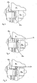
- the angle rails 20a, 20b are adjusted by means of a respective guide slot 28a, 28b in their altitude.
- the angle rails 20a, 20b are guided on the frame 12 of the load-receiving means 10 so that they only in the vertical direction, in the representation of Fig. 1 and the Fig. 2 So from top to bottom or from bottom to top, can be moved.
- the slotted guides 28a, 28b are connected to each other by means of a crossbar 30, so that they can be moved simultaneously and synchronously relative to the frame 12 of the load receiving means 10 and parallel to the transport table 18. A detailed explanation of the slide guides 28a, 28b will be given below in connection with FIG Fig. 11 ,
- the presentation of the Fig. 2 shows the detail II of Fig. 1 increased.
- Good to see is the conveyor belt 14a and the angle rail 20a shown in the raised state.
- a cam 24 can be seen on the cam chain 22a.
- the cam 24 is attached to a chain link 26.
- the cam chain 22a is deflected by a sprocket 32, which in turn is arranged on a shaft which is guided by a side wall 34a of the load-receiving means 10.
- the side wall 34a is fixedly connected to the frame 12.
- the sprocket 32 opposite side of the side wall 34 a a pulley 36 is disposed on the shaft, which in Fig. 1 can be seen.
- the pulley 36 is connected to two other pulleys and a shaft 40 which is guided under the transport table 18 through on the opposite side of the load receiving means 10 and is connected there by means of a similar arrangement with a sprocket, which in the illustration of the Fig. 1 right cam chain 22b drives. Both cam chains 22a, 22b can thus be moved synchronously with each other.
- the presentation of the Fig. 3 shows the load-receiving means 10 of Fig. 1 , wherein the angle rails 20a, 20b are in the lowered position.
- a bearing surface of the angle rails 20a, 20b for load units both below an upper side of the conveyor belts 14a, 14b and below an upper surface of the cam 24 on the cam chains 22a, 22b is arranged.
- a load unit could thus rest on the tops of the cams 24 as the conveyor belts 14a, 14b move.
- a further load unit can be conveyed by means of the conveyor belts 14a, 14b onto the load receiving means 10 or be carried away by the load receiving means 10.
- load units can be conveyed onto the load receiving means 10 and come to lie with their lower sides above the bearing surfaces of the angle rails 20a, 20b.
- FIGS. 5, 6 and 7 show different operating states of the load handling device according to the invention.
- a cargo unit is shown in sections in these figures and designated by the reference numeral 44.
- the angle rail 20 a lowered and the cam chain 22 a has been moved to a position in which no cam is below the load unit 44.
- the cam 24 is located yourself in an in Fig. 5 invisible position.
- the load unit 44 thus lies exclusively on the conveyor belt 14a and in the representation of Fig. 5 unrecognizable conveyor belt 14b.
- the cargo unit 44 thus be promoted by the load receiving means 10 down, for example, in a shelf space.
- the load unit 44 can be conveyed to the load receiving means 10, for example, from a shelf space or a Einlagerschreibgabeplatz.
- the presentation of the Fig. 6 shows the excavating device and especially the angle rail 20a in the raised state.
- the load unit 44 thus lies exclusively on the angle rail 20a and the in Fig. 6 not shown angle rail 20b.
- the conveyor belt 14a and the cam chain 22a can thus be moved freely and, for example, a plurality of cams 24 can be placed below the load unit 44, as by means of the angle rail 20a, the load unit 44 is raised above the level at which the top of the cam 24 are located.
- FIG. 7 shows then another operating state by the load unit 44 rests exclusively on the cam 24.
- the cams 24 thus serve as spacers in order to keep the load unit 44 in a state lifted off the conveyor belt 14a, although the excavating device with the angle rail 20a is already lowered again below the level of the conveyor belt 14a.
- further load units can be accommodated on the load receiving means 10 without the load unit 44 being displaced relative to the load receiving means 10.
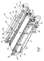
- FIG. 8 shows the load-receiving means 10 of Fig. 1 in a view from diagonally above. It should be noted that the conveyor belts 14a, 14b have been removed, so that deflection rollers 46 can be seen for the conveyor belts.
- cam chains 22a, 22b wherein in the illustration of Fig. 8 only the cam chain 22b can be seen in the region of its upper run, each having three cam groups 48a, 48b and 48c, each formed of thirteen directly adjacent cams 24 are formed.
- Each cam group 48a, 48b, 48c thus provides an approximately continuous bearing surface for a cargo unit.
- the cams 24 since each of the cams 24 is mounted on another chain link of the cam chain 22b, the cams 24 may deflect away from each other when deflected about the sprockets 32.
- the sprockets 32 can thereby have a small diameter and the cam chains 22a, 22b and the drive can be accommodated in the load-receiving means 10 to save space.
- the angle rail 20b to recognize is identical.
- the angle rail 20b extends substantially over the entire length of the load receiving means 10 and is designed so long that four Ladegutakuen that juxtaposed approximately cover the entire length of the transport table 18, can be raised simultaneously.
- the angle rails 20a, 20b are not bent at right angles, but have between the horizontally disposed support surface 50 and the lateral stop surface 52 at an angle of more than 90 °.
- a cargo unit be slightly laterally displaced or skewed on the conveyor belts 14a, 14b or the groups of cams 48a, 48b, 48c, then this cargo unit is automatically aligned as the angle rails 20a, 20b are raised, that their side edges run exactly parallel to the angle rails 20a, 20b.
- the angle rails 20a, 20b are guided on the side walls 34a, 34b of the load-receiving means 10 such that they can only be moved perpendicular to the transport table 18.
- the angle rails 20a, 20b are driven by means of the slide guides 28a, 28b, which are described below in connection with FIG Fig. 11 be explained.
- a total of four L-shaped end stops 56 can be seen, which are each arranged non-rotatably at a free end of shafts 42a, 42b.
- the shafts 42a, 42b are in turn moved by means of a drive rod 54 which is moved mechanically, electrically, hydraulically or pneumatically.
- the shafts 42a, 42b are each rotatably mounted on the side parts 34a, 34b.
- the end stops 56 can be moved in the transport path of load units on the load-receiving means 10. In the presentation of the Fig. 8 these L-shaped end stops 56 are shown in their release position.
- end stops 56 By rotation of the shafts 42a, 42b, these end stops 56 can be pivoted so that cargo units located on the load-receiving means 10 can not be conveyed down therefrom.
- the end stops 56 are moved to their blocking position when the load-receiving means 10 is moved along a rack aisle, to prevent acceleration units from moving load units from the load-receiving means 10 or from a malfunction of the drive motors for the conveyor belts 14a, 14b or the cam chains 22a. 22b load units are moved down from the transport table 18.
- the presentation of the Fig. 9 shows the load-receiving means 10 of Fig. 8 when the transport table 18 is extended.
- the transport table 18 is displaceably arranged on an intermediate slide 58, which in turn is displaceably arranged on slide guides 60, wherein the carriage guides 60 are fixedly connected to the frame 12 of the load receiving means 10.
- the transport table 18 can be extended by its entire length. This is necessary, for example, if the load-receiving means 10 is arranged in front of a shelf space and at the same time four load units or one load unit with fourfold depth is to be transferred to the transport table 18.
- the transport table 18 is then moved together with the conveyor belts 14a, 14b under the cargo units on the shelf.
- the load-receiving means 10 is then raised in total and the transport table 18 is again in the in the Fig. 8 shown position moves. After folding in the end stops 56, the load-receiving means 10 can then be moved within the rack aisle.
- Fig. 10 shows the detail X the Fig. 9 increased.
- chain links 26 are shown only schematically as a continuous band.
- the cam chain 22a consists of individual, rotatably connected chain links 26. Good to recognize the sprocket 32, which deflects the cam chain 22a.
- Each of the cams 24 is attached to another chain link 26, so that the cams 24, which are in the in Fig. 10 illustrated position form an approximately continuous top for stopping a cargo unit, can unfold in the range of the sprocket 32 and thereby the cam chain 22a is easily deflected.
- the cams 24 may for example be formed as chain links and hinged together.
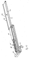
- the presentation of the Fig. 11 shows the excavating device 62, wherein only the essential parts for the excavating were shown and, for example, the side parts of the frame have not been shown for clarity.
- the excavating device 62 has the two angle rails 20a, 20b, which are each connected to an auxiliary frame 64a, 64b and which can be raised and lowered by means of the slide guides 28a, 28b.
- the subframes 64a, 64b are by means of longitudinal guides 66 each mounted in a vertical direction displaceable on the side parts 34a, 34b, wherein the side part 34a in the illustration of Fig. 11 not shown.
- the subframes 64a, 64b are each provided with two rollers 68, which run on sliding blocks 70a, 70b.
- the link slides 70a, 70b are in turn arranged by means of longitudinal guides 72 parallel to a transport direction on the load-receiving means 10, that is parallel to the angle rails 20a, 20b displaceable on the side parts 34a, 34b. If the sliders 70a, 70b, starting from the in Fig. 11 shifted position, in Fig. 11 that is, down to the right, the rollers 68 reach ramps 74 on the sliding links 70a, 70b and the angle rails 20a, 20b are raised in the vertical direction.
- the excavating device 62 it is also possible to raise heavy load units without difficulty, and the excavating device 62 has a comparatively simple construction, but above all a reliable design.
- a displacement of the slide links 70a, 70b can be done for example by means of a pneumatic or hydraulic cylinder, not shown.
- the angle rails 20a, 20b have a length that allows the lifting of four juxtaposed Ladegutajien. By means of the slide links 70a, 70b can be ensured that the two angle rails 20a, 20b are raised exactly parallel and in its horizontal position remaining synchronous.
- FIG. 12 shows the transport table 18 in its extended position, with the sake of clarity, numerous parts of the load-receiving means 10 have been omitted.
- the transport belts 14a, 14b are laid in a so-called omega arrangement, since, for the example of the transport belt 14a, an unillustrated drive wheel is arranged in a loop 76 of the drive belt 14a, which has approximately the shape of an upside-down omega.
- This so-called omega arrangement with the loop 76 has the advantage that the drive motor for the drive belt 14a below the carriage assembly with the carriage guides 60, the intermediate carriage 58 and the transport table 18 can be arranged.
- the carriage drive for the transport table 18 is effected with a separate motor 78, which causes an extension movement of the transport table 18 via drive belt 80.
- the transport table 18 can be of the in Fig. 12 shown, fully extended to the right position on a center position, as for example in Fig. 8 is shown, are moved in a extended by its entire length to the left position.
- the load-receiving means 10 can thereby serve shelf space, which are arranged on the right or left of a rack aisle.
- the drive motor 78 for the carriage drive is so tuned by means of a control on the drive motor for the conveyor belt 14a, 14b that a portion 82a, 82b of the conveyor belt 14a, 14b, which is during the carriage movement adjacent to the transport table 18, during the entire extension process the carriage assembly is not moved relative to the transport table 18.
- On the transport belt 14a, 14b seated cargo units thus remain relative to the transport table 18 at rest, even if this starting from his in Fig. 8 shown center position in the in Fig. 12 shown, fully extended position moves.
- FIG. 13 shows different ways of occupying a load-carrying means 10 with cargo units.
- the double-length load unit 44e is left-justified, and next to it, the two load units 44a, 44b each having a single length are arranged.
- the load unit 44a is left-aligned and next to it also the load unit 44b, which is also simply long, is arranged. Right-justified is the double-length load unit 44e arranged.
- the load unit 44a is left-aligned, the load unit 44b is right-justified, and between these load units 44a, 44b, each having a single length, the double-length load unit 44e is arranged.
- Fig. 13 shows, its great flexibility in the transport of different lengths Ladegutajien can be seen.
- the excavating device and the spacers according to the invention it is possible to use any of the Fig. 13 illustrated load units 44a to 44f lift from the conveyor belt or to leave this on, to effect a transport from the load-receiving means or up this. Transferred to the representation of Fig. 13
- the load unit 44d can then likewise be transported away to the opposite side without the load units 44b, 44c changing their position relative to the load receiving means 10.
- the fourth line it is possible by the combination of the excavating device with the spacers, for example, first carry away the load unit 44a to the left and the load units 44b, 44e, however, leave on the load-carrying means. In order subsequently also to allow the removal of the load unit 44b to the left, then the load units 44b, 44e can be displaced on the load receiving means 10 until the load unit 44b is arranged left-aligned. This displacement can also take place during a movement of the load-receiving means 10 along a storage lane. Alternatively, however, it is also possible, for example, to take over a further, simply deep, cargo unit to the load units 44b, 44e on the load-receiving means 10.
- Fig. 15 a total of four simple deep load units 44a, 44b, 44c and 44d are arranged on the load-receiving means 10.
- the cam chains 22a, 22b are then moved so that cams 24 are arranged below the load units 44a, 44b and 44c, see line A.
- line B which of course could also be achieved by lowering the excavating device
- the load unit 44d is still on the conveyor belts 14a, 14b and can, see row C, be transported to the right from the load-receiving means 10 down.
- FIG. 16 Another possibility of flexible use shows the schematic representation of Fig. 16 , According to lines A and B, the cam chains 22a, 22b are moved in the excavated state of the load units 44a, 44b, 44c and 44d so that only below the load units 44a, 44b cams are arranged. After lifting the cam chains 22a, 22b are thus still only the load units 44c, 44d on the conveyor belts 14a, 14b and can, see row D, be transported together to the right.
- the presentation of the Fig. 14 schematically shows a conveyor system 80 according to the invention with a load receiving means 10, a Einlagerschreibgabeplatz 82, a Auslagerschreibgabeplatz 84, an intermediate memory space 86 and two shelves 88, 90, between which a rack aisle 92 is arranged.
- the load-receiving means 10 can along a double arrow 94 in the rack aisle 92 and also, perpendicular to the plane of the paper Fig. 14 , be moved in height direction to all shelves on the shelves 88, 90 can approach.
- the load-receiving means 10 can be arranged exactly between the Einlagerübergabeplatz 82 and the Auslagerschreibgabeplatz 84, compared to the representation of Fig.
- a schematically illustrated conveyor system is arranged by means of the further load units 44e and 44f can be transferred in the direction of the two arrows 100 to the Einlagerübergabeplatz 82.
- the load unit 44e is simply deep, the load unit 44f executed twice deep.
- the load units 44e and 44f are conveyed to the storage transfer station 82 and there arranged, for example, by shifting to the left or right so that whenever possible cargo units with a total of four times the length can be transferred together to the load receiving means 10 so that it is always fully occupied ,
- the outsourcing transfer point 84 is also followed by conveyor technology, with which load units can be transported in the direction of the arrows 102.
- the conveyor 80 is provided upstream of the Einlagerübergabeplatzes 82 with the intermediate memory space 86. Individual load units can be moved to the intermediate memory space 86 and transferred from this back to the conveyor technology, as by the Double arrow 104 is indicated.
- the intermediate memory space 86 can thereby be used as a waiting area, if, for example, the simply deep load unit 44e is to be parked, since subsequently several complete loads are conveyed to the load receiving means 10, which are to be moved to the same or adjacent shelf spaces.
- the load unit 44e can then remain in the intermediate storage space 86 until further load units are conveyed which, on the one hand, allow complete occupancy of the load receiving means 10 together with the load unit 44e and should be moved to spatially adjacent shelf spaces, such as the load unit 44e.
- the number of empty trips or trips with incomplete occupancy of the lifting device 10 can be substantially reduced.
- an increase in the throughput of the conveyor 80 is possible or the load receiving means 10 and the Einlagerübergabeplatz 82 and the Auslagerschreibgabeplatz 84 can be operated at a comparatively low speed, for example, to achieve large maintenance intervals and to get along with low accelerations of the cargo.
Claims (15)
- Moyen de préhension des charges (10) pour un transstockeur, comprenant au moins une bande transporteuse (14a, 14b) pour unités de charge (44) et un dispositif de levage (62) pour unités de charge (44) destiné, selon les besoins, à soulever des unités de charge (44) au-dessus de la bande transporteuse (14a, 14b) et à les déposer de nouveau sur celle-ci, caractérisé en ce qu'est prévu au moins un écarteur (24), sachant que l'écarteur (24) est mobile sur le moyen de préhension des charges (10) et peut être placé relativement aux unités de charge (44) sous au moins une unité de charge (44) déjà soulevée par le dispositif de levage (62), afin de maintenir l'au moins une unité de charge (44) dans un état soulevé au-dessus de la bande transporteuse (14a, 14b) indépendamment de la position du dispositif de levage (62).
- Moyen de préhension des charges selon la revendication 1, caractérisé en ce que l'au moins un écarteur est disposé de manière mobile le long d'une voie de transport sur le moyen de préhension des charges (10).
- Moyen de préhension des charges selon l'une des revendications précédentes, caractérisé en ce que l'au moins un écarteur est disposé sur un moyen d'entraînement tournant autour du moyen de préhension des charges (10).
- Moyen de préhension des charges selon la revendication 3, caractérisé en ce que plusieurs écarteurs sous forme de taquets (24) sont disposés sur le moyen d'entraînement tournant autour du moyen de préhension des charges (10).
- Moyen de préhension des charges selon la revendication 4, caractérisé en ce que sur le moyen d'entraînement sont disposés au moins deux groupes de taquets (48a, 48b, 48c) distants l'un de l'autre, sachant qu'une unité de charge (44) peut être associée à chaque groupe de taquets (48a, 48b, 48c).
- Moyen de préhension des charges selon l'une des revendications précédentes, caractérisé en ce que le dispositif de levage (62) est conçu pour soulever simultanément toutes les unités de charge (44) se trouvant sur la bande transporteuse (14a, 14b).
- Moyen de préhension des charges selon l'une des revendications précédentes, caractérisé en ce que le dispositif de levage (62) présente au moins deux barres de butée qui peuvent s'appliquer sur une unité de charge (44) latéralement et/ou par dessous.
- Moyen de préhension des charges selon au moins une des revendications précédentes, caractérisé en ce qu'est prévue une table transporteuse (18) déployable, la bande transporteuse (14a, 14b) étant guidée dans la zone de la face supérieure de la table transporteuse (18).
- Moyen de préhension des charges selon la revendication 8, caractérisé en ce que des moteurs d'entraînement distincts sont prévus pour entraîner respectivement la bande transporteuse (14a, 14b) et la table transporteuse (18), sachant que le moteur d'entraînement de la bande transporteuse (14a, 14b) est disposé ou peut être commandé de manière telle que, dans la zone de la face supérieure de la table transporteuse (18), la bande transporteuse (14a, 14b) ne se déplace pas par rapport à la face supérieure de la table transporteuse (18) lorsque cette dernière est déployée.
- Installation de transport comprenant un transstockeur avec un moyen de préhension des charges (10) selon au moins une des revendications précédentes, caractérisée en ce qu'est prévu au moins un emplacement de stockage intermédiaire (86) pour au moins une unité de charge (44).
- Installation de transport selon la revendication 10, caractérisée en ce que l'au moins un emplacement de stockage intermédiaire (86) est prévu à proximité d'un poste de transfert et de stockage (82).
- Installation de transport selon la revendication 10 ou 11, caractérisée en ce qu'un poste de transfert et de stockage (82) est disposé en face d'un poste de transfert et de déstockage (84) de manière telle que le moyen de préhension des charges (10) peut être disposé entre le poste de transfert et de stockage (82) et le poste de transfert et de déstockage (84).
- Procédé de fonctionnement d'une installation de transport dotée d'au moins un transstockeur avec un moyen de préhension des charges (10) selon l'une des revendications précédentes, caractérisé par le transfert d'au moins une unité de charge (44) sur le moyen de préhension des charges (10), par le soulèvement de l'unité de charge d'une bande transporteuse (14a, 14b) du moyen de préhension des charges (10), suivi du transfert, du transstockage, du regroupement, et/ou du déstockage dans un casier de rayonnage d'au moins une autre unité de charge (44).
- Procédé selon la revendication 13, caractérisé par la simultanéité du transfert d'unités de charge (44) provenant du poste de transfert et de stockage (82) sur le moyen de préhension des charges (10), et du dépôt d'unités de charge (44) provenant du moyen de préhension des charges (10) sur le poste de transfert et de déstockage (84).
- Procédé selon la revendication 13 ou 14, caractérisé, au niveau d'un emplacement de stockage intermédiaire (86), par la modification de l'ordre de plusieurs unités de charge (44) disposées sur le moyen de préhension des charges (10), et/ou par le tri par hauteur d'unités de charge (44) sur le moyen de préhension des charges (10).
Applications Claiming Priority (1)
| Application Number | Priority Date | Filing Date | Title |
|---|---|---|---|
| DE200810064533 DE102008064533A1 (de) | 2008-12-19 | 2008-12-19 | Lastaufnahmevorrichtung für ein Regalbediengerät, Förderanlage mit einem Regalbediengerät und Verfahren zum Betreiben eines Regalbediengeräts |
Publications (3)
| Publication Number | Publication Date |
|---|---|
| EP2199229A2 EP2199229A2 (fr) | 2010-06-23 |
| EP2199229A3 EP2199229A3 (fr) | 2011-05-18 |
| EP2199229B1 true EP2199229B1 (fr) | 2012-08-29 |
Family
ID=41820196
Family Applications (2)
| Application Number | Title | Priority Date | Filing Date |
|---|---|---|---|
| EP20090015114 Not-in-force EP2199229B1 (fr) | 2008-12-19 | 2009-12-07 | Moyen de réception de charge pour un appareil de commande de rayonnage, installation de transport dotée d'un appareil de commande de rayonnage et procédé de fonctionnement de l'installation de transport |
| EP09015113A Not-in-force EP2199248B1 (fr) | 2008-12-19 | 2009-12-07 | Méthode pour opérer une installation de convoyage. |
Family Applications After (1)
| Application Number | Title | Priority Date | Filing Date |
|---|---|---|---|
| EP09015113A Not-in-force EP2199248B1 (fr) | 2008-12-19 | 2009-12-07 | Méthode pour opérer une installation de convoyage. |
Country Status (3)
| Country | Link |
|---|---|
| EP (2) | EP2199229B1 (fr) |
| DE (1) | DE102008064533A1 (fr) |
| ES (2) | ES2393047T3 (fr) |
Families Citing this family (7)
| Publication number | Priority date | Publication date | Assignee | Title |
|---|---|---|---|---|
| NL2008454C2 (nl) * | 2012-03-09 | 2013-09-10 | Vanderlande Ind Bv | Wagen alsmede opslagsysteem voorzien van een dergelijke wagen. |
| DE102012220193A1 (de) * | 2012-11-06 | 2014-05-08 | Kardex Produktion Deutschland Gmbh | Lagergut-Extraktor für ein automatisches Lagersystem |
| DE102015213548A1 (de) * | 2015-07-17 | 2017-01-19 | Cewe Stiftung & Co. Kgaa | Objektaufnahmeeinrichtung zum Aufnehmen und Abgeben von Objekten |
| CA3052299A1 (fr) | 2017-02-24 | 2018-08-30 | Opex Corporation | Systemes et procedes de stockage et de recuperation automatises |
| JP2020508944A (ja) | 2017-02-24 | 2020-03-26 | オペックス コーポレーション | 自動格納及び取得システム |
| CN108001927B (zh) * | 2018-01-13 | 2024-04-26 | 上海海洋大学 | 一种双层排气管物料架 |
| PT116648A (pt) * | 2020-08-19 | 2022-02-21 | Imeguisa Portugal Ind Metalicas Reunidas S A | Sistema de transporte de plataformas móveis com braço extensível |
Family Cites Families (15)
| Publication number | Priority date | Publication date | Assignee | Title |
|---|---|---|---|---|
| US4925005A (en) * | 1988-10-13 | 1990-05-15 | Simplimatic Engineering Company | Accumulating conveyor |
| DE4031883C2 (de) * | 1990-10-08 | 1998-06-10 | Koettgen Lagertechnik Gmbh & C | Aufnahme- und Abgabesystem für Paletten und Behälter |
| DE4205856B4 (de) * | 1991-04-13 | 2006-04-13 | C. Haushahn Gmbh & Co | Vorrichtung zur Lastaufnahme |
| JPH05132300A (ja) * | 1991-11-11 | 1993-05-28 | Nippon Yusoki Co Ltd | 有人ラツクフオークリフトの情報処理制御システム |
| JPH08175623A (ja) * | 1994-12-21 | 1996-07-09 | Daifuku Co Ltd | 昇降装置及びその昇降装置を備えた保管設備 |
| DE19801856C2 (de) * | 1998-01-20 | 1999-11-18 | Doerfel Kg Ihr Partner | Verfahren und Vorrichtung zum Beschicken und Entnehmen von Behältern in ein bzw. aus einem Regal |
| DE19836764C2 (de) * | 1998-08-13 | 2000-05-25 | Siemens Ag | Anordnung zur Vereinzelung von nebeneinaderliegenden Paketen |
| DE29921514U1 (de) * | 1999-12-07 | 2000-02-24 | Psb Gmbh Materialflus & Logist | Vorrichtung zum Transportieren von Stückgütern |
| DE20021029U1 (de) | 2000-12-12 | 2001-03-29 | Viastore Systems Gmbh | Fördergerät |
| KR100444960B1 (ko) * | 2002-06-03 | 2004-08-21 | 삼성전자주식회사 | 자동창고 시스템의 반송 시간 예측 방법 |
| SE0402030L (sv) * | 2004-08-16 | 2006-02-17 | Moving Ab | System och förfarande för lagerhantering |
| US7722307B2 (en) * | 2004-09-03 | 2010-05-25 | Daifuku America Corporation | System and method for handling stocked items |
| DE102004063588A1 (de) * | 2004-12-30 | 2006-07-13 | Siemens Ag | Regalbediengerät und Hochregallager mit einem solchen Regalbediengerät |
| US8538692B2 (en) * | 2006-06-19 | 2013-09-17 | Amazon Technologies, Inc. | System and method for generating a path for a mobile drive unit |
| DE102006049411A1 (de) * | 2006-10-16 | 2008-04-17 | Psb Intralogistics Gmbh | Vorrichtung zum Transportieren von Behältern |
-
2008
- 2008-12-19 DE DE200810064533 patent/DE102008064533A1/de not_active Withdrawn
-
2009
- 2009-12-07 EP EP20090015114 patent/EP2199229B1/fr not_active Not-in-force
- 2009-12-07 ES ES09015114T patent/ES2393047T3/es active Active
- 2009-12-07 ES ES09015113T patent/ES2387179T3/es active Active
- 2009-12-07 EP EP09015113A patent/EP2199248B1/fr not_active Not-in-force
Also Published As
| Publication number | Publication date |
|---|---|
| ES2387179T3 (es) | 2012-09-17 |
| EP2199229A2 (fr) | 2010-06-23 |
| EP2199248B1 (fr) | 2012-05-30 |
| EP2199248A3 (fr) | 2010-10-27 |
| EP2199248A2 (fr) | 2010-06-23 |
| ES2393047T3 (es) | 2012-12-18 |
| EP2199229A3 (fr) | 2011-05-18 |
| DE102008064533A1 (de) | 2010-07-01 |
Similar Documents
| Publication | Publication Date | Title |
|---|---|---|
| EP2794432B1 (fr) | Système de stockage sur rayonnages et son procédé de fonctionnement | |
| EP1695925B1 (fr) | Magasin à rayonnage et procédé pour transférer d'articles dans un magasin à rayonnage | |
| AT516410B1 (de) | Verfahren zum Einlagern von Stückgütern in ein Lagerregal und Lagersystem | |
| EP2199229B1 (fr) | Moyen de réception de charge pour un appareil de commande de rayonnage, installation de transport dotée d'un appareil de commande de rayonnage et procédé de fonctionnement de l'installation de transport | |
| EP1638866B1 (fr) | Procede et dispositif pour manipuler des auxiliaires de chargement | |
| EP1908711B1 (fr) | Dispositif de levage d'une couche constituée d'une multitude de récipients ou analogues | |
| EP2609021B1 (fr) | Système de rayonnage pour le stockage de produits à stocker | |
| DE102008015278B4 (de) | Palettiervorrichtung | |
| AT506918B1 (de) | Aufnahmevorrichtung für ein förderfahrzeug | |
| EP0396005A2 (fr) | Rayonnage haut pour stocker et déstocker des marchandises en forme de rouleau notamment des rouleaux de papier | |
| EP1676808A2 (fr) | Transstockeur et rayonnage d'emmagasinage surélevé avec un tel transstockeur | |
| DE3504491A1 (de) | Vorrichtung zum anlegen von bogen | |
| DE102012220193A1 (de) | Lagergut-Extraktor für ein automatisches Lagersystem | |
| DE4338717A1 (de) | Automatische Park- und Lagereinrichtung für Kraftfahrzeuge | |
| EP0589844A1 (fr) | Magasin à haute performance avec des moyens pour stocker et prélever des marchandises | |
| EP2746193A1 (fr) | Entrepôt et appareil de commande d'entrepôt avec fonction de passage | |
| EP3210917A1 (fr) | Stockage vertical avec moyens de levage pour marchandises | |
| EP1157947B1 (fr) | Convoyeur vertical | |
| DE102005046821A1 (de) | Horizontal-Umlauflagersystem | |
| DE102012220194A1 (de) | Automatisches Lagersystem mit zwei nebeneinander angeordneten Lagersegmenten und gekoppelten Lagergut-Extraktoren | |
| EP1837295B1 (fr) | Dispositif doté d'aires de stockage, en particulier pour la réception de portes-pièces, tout comme système doté d'une bande convoyeuse et d'un dispositif destiné à la réception de portes-pièces | |
| CH628852A5 (en) | Storage apparatus for palletised goods | |
| AT500227B1 (de) | Transportwagen zum ein- und auslagern von transportgut | |
| DE2510147A1 (de) | Verfahren und einrichtung zum ein- und auslagern von waren | |
| DE2220846A1 (de) | Verfahren und vorrichtung zum zerlegen von ziegelstapeln |
Legal Events
| Date | Code | Title | Description |
|---|---|---|---|
| PUAI | Public reference made under article 153(3) epc to a published international application that has entered the european phase |
Free format text: ORIGINAL CODE: 0009012 |
|
| AK | Designated contracting states |
Kind code of ref document: A2 Designated state(s): AT BE BG CH CY CZ DE DK EE ES FI FR GB GR HR HU IE IS IT LI LT LU LV MC MK MT NL NO PL PT RO SE SI SK SM TR |
|
| AX | Request for extension of the european patent |
Extension state: AL BA RS |
|
| PUAL | Search report despatched |
Free format text: ORIGINAL CODE: 0009013 |
|
| AK | Designated contracting states |
Kind code of ref document: A3 Designated state(s): AT BE BG CH CY CZ DE DK EE ES FI FR GB GR HR HU IE IS IT LI LT LU LV MC MK MT NL NO PL PT RO SE SI SK SM TR |
|
| AX | Request for extension of the european patent |
Extension state: AL BA RS |
|
| 17P | Request for examination filed |
Effective date: 20110727 |
|
| GRAP | Despatch of communication of intention to grant a patent |
Free format text: ORIGINAL CODE: EPIDOSNIGR1 |
|
| GRAS | Grant fee paid |
Free format text: ORIGINAL CODE: EPIDOSNIGR3 |
|
| GRAA | (expected) grant |
Free format text: ORIGINAL CODE: 0009210 |
|
| AK | Designated contracting states |
Kind code of ref document: B1 Designated state(s): AT BE BG CH CY CZ DE DK EE ES FI FR GB GR HR HU IE IS IT LI LT LU LV MC MK MT NL NO PL PT RO SE SI SK SM TR |
|
| REG | Reference to a national code |
Ref country code: GB Ref legal event code: FG4D Free format text: NOT ENGLISH |
|
| REG | Reference to a national code |
Ref country code: CH Ref legal event code: EP |
|
| REG | Reference to a national code |
Ref country code: AT Ref legal event code: REF Ref document number: 572943 Country of ref document: AT Kind code of ref document: T Effective date: 20120915 |
|
| REG | Reference to a national code |
Ref country code: IE Ref legal event code: FG4D Free format text: LANGUAGE OF EP DOCUMENT: GERMAN |
|
| REG | Reference to a national code |
Ref country code: DE Ref legal event code: R096 Ref document number: 502009004494 Country of ref document: DE Effective date: 20121025 |
|
| REG | Reference to a national code |
Ref country code: CH Ref legal event code: NV Representative=s name: ZIMMERLI, WAGNER & PARTNER AG |
|
| REG | Reference to a national code |
Ref country code: NL Ref legal event code: T3 |
|
| REG | Reference to a national code |
Ref country code: ES Ref legal event code: FG2A Ref document number: 2393047 Country of ref document: ES Kind code of ref document: T3 Effective date: 20121218 |
|
| REG | Reference to a national code |
Ref country code: LT Ref legal event code: MG4D Effective date: 20120829 |
|
| PG25 | Lapsed in a contracting state [announced via postgrant information from national office to epo] |
Ref country code: FI Free format text: LAPSE BECAUSE OF FAILURE TO SUBMIT A TRANSLATION OF THE DESCRIPTION OR TO PAY THE FEE WITHIN THE PRESCRIBED TIME-LIMIT Effective date: 20120829 Ref country code: HR Free format text: LAPSE BECAUSE OF FAILURE TO SUBMIT A TRANSLATION OF THE DESCRIPTION OR TO PAY THE FEE WITHIN THE PRESCRIBED TIME-LIMIT Effective date: 20120829 Ref country code: IS Free format text: LAPSE BECAUSE OF FAILURE TO SUBMIT A TRANSLATION OF THE DESCRIPTION OR TO PAY THE FEE WITHIN THE PRESCRIBED TIME-LIMIT Effective date: 20121229 Ref country code: CY Free format text: LAPSE BECAUSE OF FAILURE TO SUBMIT A TRANSLATION OF THE DESCRIPTION OR TO PAY THE FEE WITHIN THE PRESCRIBED TIME-LIMIT Effective date: 20120829 Ref country code: NO Free format text: LAPSE BECAUSE OF FAILURE TO SUBMIT A TRANSLATION OF THE DESCRIPTION OR TO PAY THE FEE WITHIN THE PRESCRIBED TIME-LIMIT Effective date: 20121129 Ref country code: LT Free format text: LAPSE BECAUSE OF FAILURE TO SUBMIT A TRANSLATION OF THE DESCRIPTION OR TO PAY THE FEE WITHIN THE PRESCRIBED TIME-LIMIT Effective date: 20120829 |
|
| PG25 | Lapsed in a contracting state [announced via postgrant information from national office to epo] |
Ref country code: SE Free format text: LAPSE BECAUSE OF FAILURE TO SUBMIT A TRANSLATION OF THE DESCRIPTION OR TO PAY THE FEE WITHIN THE PRESCRIBED TIME-LIMIT Effective date: 20120829 Ref country code: LV Free format text: LAPSE BECAUSE OF FAILURE TO SUBMIT A TRANSLATION OF THE DESCRIPTION OR TO PAY THE FEE WITHIN THE PRESCRIBED TIME-LIMIT Effective date: 20120829 Ref country code: PT Free format text: LAPSE BECAUSE OF FAILURE TO SUBMIT A TRANSLATION OF THE DESCRIPTION OR TO PAY THE FEE WITHIN THE PRESCRIBED TIME-LIMIT Effective date: 20121231 Ref country code: SI Free format text: LAPSE BECAUSE OF FAILURE TO SUBMIT A TRANSLATION OF THE DESCRIPTION OR TO PAY THE FEE WITHIN THE PRESCRIBED TIME-LIMIT Effective date: 20120829 Ref country code: GR Free format text: LAPSE BECAUSE OF FAILURE TO SUBMIT A TRANSLATION OF THE DESCRIPTION OR TO PAY THE FEE WITHIN THE PRESCRIBED TIME-LIMIT Effective date: 20121130 |
|
| PG25 | Lapsed in a contracting state [announced via postgrant information from national office to epo] |
Ref country code: EE Free format text: LAPSE BECAUSE OF FAILURE TO SUBMIT A TRANSLATION OF THE DESCRIPTION OR TO PAY THE FEE WITHIN THE PRESCRIBED TIME-LIMIT Effective date: 20120829 Ref country code: RO Free format text: LAPSE BECAUSE OF FAILURE TO SUBMIT A TRANSLATION OF THE DESCRIPTION OR TO PAY THE FEE WITHIN THE PRESCRIBED TIME-LIMIT Effective date: 20120829 Ref country code: CZ Free format text: LAPSE BECAUSE OF FAILURE TO SUBMIT A TRANSLATION OF THE DESCRIPTION OR TO PAY THE FEE WITHIN THE PRESCRIBED TIME-LIMIT Effective date: 20120829 Ref country code: DK Free format text: LAPSE BECAUSE OF FAILURE TO SUBMIT A TRANSLATION OF THE DESCRIPTION OR TO PAY THE FEE WITHIN THE PRESCRIBED TIME-LIMIT Effective date: 20120829 |
|
| PG25 | Lapsed in a contracting state [announced via postgrant information from national office to epo] |
Ref country code: IT Free format text: LAPSE BECAUSE OF FAILURE TO SUBMIT A TRANSLATION OF THE DESCRIPTION OR TO PAY THE FEE WITHIN THE PRESCRIBED TIME-LIMIT Effective date: 20120829 Ref country code: SK Free format text: LAPSE BECAUSE OF FAILURE TO SUBMIT A TRANSLATION OF THE DESCRIPTION OR TO PAY THE FEE WITHIN THE PRESCRIBED TIME-LIMIT Effective date: 20120829 Ref country code: PL Free format text: LAPSE BECAUSE OF FAILURE TO SUBMIT A TRANSLATION OF THE DESCRIPTION OR TO PAY THE FEE WITHIN THE PRESCRIBED TIME-LIMIT Effective date: 20120829 |
|
| PLBE | No opposition filed within time limit |
Free format text: ORIGINAL CODE: 0009261 |
|
| STAA | Information on the status of an ep patent application or granted ep patent |
Free format text: STATUS: NO OPPOSITION FILED WITHIN TIME LIMIT |
|
| PG25 | Lapsed in a contracting state [announced via postgrant information from national office to epo] |
Ref country code: BG Free format text: LAPSE BECAUSE OF FAILURE TO SUBMIT A TRANSLATION OF THE DESCRIPTION OR TO PAY THE FEE WITHIN THE PRESCRIBED TIME-LIMIT Effective date: 20121129 Ref country code: MC Free format text: LAPSE BECAUSE OF NON-PAYMENT OF DUE FEES Effective date: 20121231 |
|
| 26N | No opposition filed |
Effective date: 20130530 |
|
| REG | Reference to a national code |
Ref country code: IE Ref legal event code: MM4A |
|
| REG | Reference to a national code |
Ref country code: DE Ref legal event code: R097 Ref document number: 502009004494 Country of ref document: DE Effective date: 20130530 |
|
| PG25 | Lapsed in a contracting state [announced via postgrant information from national office to epo] |
Ref country code: IE Free format text: LAPSE BECAUSE OF NON-PAYMENT OF DUE FEES Effective date: 20121207 |
|
| PG25 | Lapsed in a contracting state [announced via postgrant information from national office to epo] |
Ref country code: MT Free format text: LAPSE BECAUSE OF FAILURE TO SUBMIT A TRANSLATION OF THE DESCRIPTION OR TO PAY THE FEE WITHIN THE PRESCRIBED TIME-LIMIT Effective date: 20120829 |
|
| REG | Reference to a national code |
Ref country code: CH Ref legal event code: NV Representative=s name: WAGNER PATENT AG, CH |
|
| PG25 | Lapsed in a contracting state [announced via postgrant information from national office to epo] |
Ref country code: TR Free format text: LAPSE BECAUSE OF FAILURE TO SUBMIT A TRANSLATION OF THE DESCRIPTION OR TO PAY THE FEE WITHIN THE PRESCRIBED TIME-LIMIT Effective date: 20120829 |
|
| PG25 | Lapsed in a contracting state [announced via postgrant information from national office to epo] |
Ref country code: SM Free format text: LAPSE BECAUSE OF FAILURE TO SUBMIT A TRANSLATION OF THE DESCRIPTION OR TO PAY THE FEE WITHIN THE PRESCRIBED TIME-LIMIT Effective date: 20120829 Ref country code: LU Free format text: LAPSE BECAUSE OF NON-PAYMENT OF DUE FEES Effective date: 20121207 |
|
| PG25 | Lapsed in a contracting state [announced via postgrant information from national office to epo] |
Ref country code: HU Free format text: LAPSE BECAUSE OF FAILURE TO SUBMIT A TRANSLATION OF THE DESCRIPTION OR TO PAY THE FEE WITHIN THE PRESCRIBED TIME-LIMIT Effective date: 20091207 |
|
| PG25 | Lapsed in a contracting state [announced via postgrant information from national office to epo] |
Ref country code: MK Free format text: LAPSE BECAUSE OF FAILURE TO SUBMIT A TRANSLATION OF THE DESCRIPTION OR TO PAY THE FEE WITHIN THE PRESCRIBED TIME-LIMIT Effective date: 20120829 |
|
| REG | Reference to a national code |
Ref country code: FR Ref legal event code: PLFP Year of fee payment: 7 |
|
| REG | Reference to a national code |
Ref country code: FR Ref legal event code: PLFP Year of fee payment: 8 |
|
| REG | Reference to a national code |
Ref country code: FR Ref legal event code: PLFP Year of fee payment: 9 |
|
| PGFP | Annual fee paid to national office [announced via postgrant information from national office to epo] |
Ref country code: NL Payment date: 20181217 Year of fee payment: 10 Ref country code: AT Payment date: 20181213 Year of fee payment: 10 |
|
| PGFP | Annual fee paid to national office [announced via postgrant information from national office to epo] |
Ref country code: BE Payment date: 20181217 Year of fee payment: 10 Ref country code: FR Payment date: 20181218 Year of fee payment: 10 Ref country code: GB Payment date: 20181219 Year of fee payment: 10 Ref country code: CH Payment date: 20181219 Year of fee payment: 10 |
|
| PGFP | Annual fee paid to national office [announced via postgrant information from national office to epo] |
Ref country code: DE Payment date: 20181219 Year of fee payment: 10 Ref country code: ES Payment date: 20190121 Year of fee payment: 10 |
|
| REG | Reference to a national code |
Ref country code: DE Ref legal event code: R119 Ref document number: 502009004494 Country of ref document: DE |
|
| REG | Reference to a national code |
Ref country code: CH Ref legal event code: PL |
|
| REG | Reference to a national code |
Ref country code: NL Ref legal event code: MM Effective date: 20200101 |
|
| REG | Reference to a national code |
Ref country code: AT Ref legal event code: MM01 Ref document number: 572943 Country of ref document: AT Kind code of ref document: T Effective date: 20191207 |
|
| REG | Reference to a national code |
Ref country code: BE Ref legal event code: MM Effective date: 20191231 |
|
| GBPC | Gb: european patent ceased through non-payment of renewal fee |
Effective date: 20191207 |
|
| PG25 | Lapsed in a contracting state [announced via postgrant information from national office to epo] |
Ref country code: NL Free format text: LAPSE BECAUSE OF NON-PAYMENT OF DUE FEES Effective date: 20200101 |
|
| PG25 | Lapsed in a contracting state [announced via postgrant information from national office to epo] |
Ref country code: GB Free format text: LAPSE BECAUSE OF NON-PAYMENT OF DUE FEES Effective date: 20191207 Ref country code: DE Free format text: LAPSE BECAUSE OF NON-PAYMENT OF DUE FEES Effective date: 20200701 |
|
| PG25 | Lapsed in a contracting state [announced via postgrant information from national office to epo] |
Ref country code: BE Free format text: LAPSE BECAUSE OF NON-PAYMENT OF DUE FEES Effective date: 20191231 Ref country code: CH Free format text: LAPSE BECAUSE OF NON-PAYMENT OF DUE FEES Effective date: 20191231 Ref country code: AT Free format text: LAPSE BECAUSE OF NON-PAYMENT OF DUE FEES Effective date: 20191207 Ref country code: LI Free format text: LAPSE BECAUSE OF NON-PAYMENT OF DUE FEES Effective date: 20191231 |
|
| PG25 | Lapsed in a contracting state [announced via postgrant information from national office to epo] |
Ref country code: FR Free format text: LAPSE BECAUSE OF NON-PAYMENT OF DUE FEES Effective date: 20191231 |
|
| REG | Reference to a national code |
Ref country code: ES Ref legal event code: FD2A Effective date: 20210601 |
|
| PG25 | Lapsed in a contracting state [announced via postgrant information from national office to epo] |
Ref country code: ES Free format text: LAPSE BECAUSE OF NON-PAYMENT OF DUE FEES Effective date: 20191208 |