EP2198490B1 - Ensemble balai et machine electrique, notamment appareil menager electrique - Google Patents
Ensemble balai et machine electrique, notamment appareil menager electrique Download PDFInfo
- Publication number
- EP2198490B1 EP2198490B1 EP08804151.2A EP08804151A EP2198490B1 EP 2198490 B1 EP2198490 B1 EP 2198490B1 EP 08804151 A EP08804151 A EP 08804151A EP 2198490 B1 EP2198490 B1 EP 2198490B1
- Authority
- EP
- European Patent Office
- Prior art keywords
- brush
- arrangement according
- sleeve
- brush arrangement
- brush sleeve
- Prior art date
- Legal status (The legal status is an assumption and is not a legal conclusion. Google has not performed a legal analysis and makes no representation as to the accuracy of the status listed.)
- Not-in-force
Links
- OKTJSMMVPCPJKN-UHFFFAOYSA-N Carbon Chemical compound [C] OKTJSMMVPCPJKN-UHFFFAOYSA-N 0.000 claims description 9
- 229910052799 carbon Inorganic materials 0.000 claims description 9
- 238000006073 displacement reaction Methods 0.000 description 8
- 230000006835 compression Effects 0.000 description 6
- 238000007906 compression Methods 0.000 description 6
- 238000004519 manufacturing process Methods 0.000 description 6
- 238000013461 design Methods 0.000 description 4
- 238000003780 insertion Methods 0.000 description 3
- 230000037431 insertion Effects 0.000 description 3
- 230000007935 neutral effect Effects 0.000 description 3
- 230000000712 assembly Effects 0.000 description 2
- 238000000429 assembly Methods 0.000 description 2
- 239000004020 conductor Substances 0.000 description 2
- 238000005553 drilling Methods 0.000 description 2
- 239000000463 material Substances 0.000 description 2
- 238000009420 retrofitting Methods 0.000 description 2
- 229910001369 Brass Inorganic materials 0.000 description 1
- 229910000831 Steel Inorganic materials 0.000 description 1
- 238000005299 abrasion Methods 0.000 description 1
- 230000015572 biosynthetic process Effects 0.000 description 1
- 230000000903 blocking effect Effects 0.000 description 1
- 239000010951 brass Substances 0.000 description 1
- 230000001419 dependent effect Effects 0.000 description 1
- 238000011161 development Methods 0.000 description 1
- 230000018109 developmental process Effects 0.000 description 1
- 239000012777 electrically insulating material Substances 0.000 description 1
- 238000005516 engineering process Methods 0.000 description 1
- -1 for example Substances 0.000 description 1
- 230000001771 impaired effect Effects 0.000 description 1
- 238000009434 installation Methods 0.000 description 1
- 238000012423 maintenance Methods 0.000 description 1
- 230000007257 malfunction Effects 0.000 description 1
- 239000012811 non-conductive material Substances 0.000 description 1
- 238000003825 pressing Methods 0.000 description 1
- 238000004080 punching Methods 0.000 description 1
- 239000010959 steel Substances 0.000 description 1
- 238000012549 training Methods 0.000 description 1
Images


Classifications
-
- H—ELECTRICITY
- H01—ELECTRIC ELEMENTS
- H01R—ELECTRICALLY-CONDUCTIVE CONNECTIONS; STRUCTURAL ASSOCIATIONS OF A PLURALITY OF MUTUALLY-INSULATED ELECTRICAL CONNECTING ELEMENTS; COUPLING DEVICES; CURRENT COLLECTORS
- H01R39/00—Rotary current collectors, distributors or interrupters
- H01R39/02—Details for dynamo electric machines
- H01R39/38—Brush holders
- H01R39/41—Brush holders cartridge type
-
- H—ELECTRICITY
- H01—ELECTRIC ELEMENTS
- H01R—ELECTRICALLY-CONDUCTIVE CONNECTIONS; STRUCTURAL ASSOCIATIONS OF A PLURALITY OF MUTUALLY-INSULATED ELECTRICAL CONNECTING ELEMENTS; COUPLING DEVICES; CURRENT COLLECTORS
- H01R39/00—Rotary current collectors, distributors or interrupters
- H01R39/02—Details for dynamo electric machines
- H01R39/38—Brush holders
- H01R39/385—Means for mechanical fixation of the brush holder
Definitions
- the invention relates to a brush assembly on an electrical machine, in particular on an electrical domestic appliance, with a brush holder receiving the brush sleeve, which can be fixed in a position of use on the housing of the machine, and an electric machine equipped therewith.
- a brush arrangement of the type mentioned is from the German patent application DE 197 17 594 A1 known.
- the relevant machine has a pot-like housing made of an electrically conductive material, in which the commutator is rotatably mounted.
- the housing holding means In the region of the end face of the housing holding means are formed, which serve to hold the carbon brushes receiving brush sleeves.
- the carbon brushes are slidably mounted in the brush sleeves and biased by a helical compression spring in the direction of the commutator. Since the brush sleeves are also electrically conductive, they must each be rigidly attached to a support member made of an electrically insulating material, in particular made of plastic, are attached. Each support member is inserted during assembly from the outside radially inwardly in the direction of the commutator in the holding means until the brush sleeves occupy their position of use.
- the contact spring of the stator comes into contact with the radial surface of the respective brush sleeve.
- locking and stop means secure the support member and thus the associated brush sleeve in all directions.
- a later replacement of support member and brush sleeve is basically by a mechanical lifting of the locking connection and a radially outward displacement possible.
- an unintentional loosening of the latching connection may occur, especially if in a fault, the temperatures in the electrical machine unusually high and the material of the support member loses strength.
- the object of the invention is to further improve the safety of such an electric machine even in the event of a fault.
- a brush arrangement of the generic type in that the brush arrangement has catch means by means of which the brush sleeve can be locked in a securing position when leaving the use position.
- the brush sleeve shifts beyond the securing position if it is released in the event of a fault. In this way, it can be ensured with the invention that the prescribed electrical safety distances are maintained even in the event of a fault, in particular with regard to the brushes and the brush sleeves.
- the catching means comprise at least one latching device which engages the brush sleeve latching in the securing position.
- a locking device can be implemented in a particularly simple and inexpensive way, the catch of the invention. This particularly ensures that Catching the brush sleeve against another directed away from the commutator displacement, especially in the direction of other electrically conductive components of the machine. This makes it possible to ensure that safety distances between the brush arrangement and other conductive components surrounding the brush arrangement are maintained even in the event of a fault.
- This embodiment of the invention may be particularly advantageous when the brush sleeve is equipped for biasing the brush with a compression spring or other suitable means which favors in the case of a release of the brush sleeve displacing this away from the commutator.
- the latching device in this case advantageously has at least one recess provided on the radial surface of the brush sleeve into which engages a latching lug in the position of use against the radial surface upon reaching the securing position and counteracts a further displacement by form-locking.
- the invention can be realized in terms of manufacturing technology particularly simple and substantially weight and cost neutral with respect to the brush sleeve.
- the recess can be formed, for example, circular or rectangular, in particular square. Such contours can be produced by drilling or, in particular, punching the recess without problems and within the framework of manufacturing steps which are required in any case, and by using tools and devices already used in the production process.
- the invention is particularly applicable to a brush assembly in which the brush sleeve is formed electrically conductive and is therefore particularly secure against unwanted contact with other electrically conductive components.
- the locking lug which is suitable for engagement in the recess when the securing position is reached is preferably formed by the contact spring of the stator, which has sufficient strength to secure the brush sleeve.
- the formation of the catch in this case requires no additional or modified components with respect to the cited prior art with the exception of the adapted brush sleeve and is therefore also essentially cost and weight neutral.
- in an exchange of the brush sleeves basically a retrofitting of existing electrical devices with catching means according to the invention, for example, in the context of an already due wear replacement, possible.
- the recesses in the radial surface of the brush sleeves are preferably arranged in the position of use in the radial direction between the commutator and the stator of the electric machine and shift in an unwanted release in the direction of the contact springs.
- the contact springs of the stator are in the position of use of the brush sleeve with advantage in the direction of the commutator inclined to the contact surface of the brush sleeve.
- the relevant contact spring engages in the recess and is deformed in a further, radially acting away from the use position on the brush sleeve force in the direction of a blocking contour.
- the invention can also be used with particular advantage in a brush arrangement in which the housing of the relevant machine is designed to be electrically conductive. Especially with such electrical devices, contact between the brush sleeve and the housing is reliably avoided.
- the brush sleeve is preferably attached at a deratigen training on an electrically insulating support member, which in turn can be used in holding means provided on the housing, in particular insertable, is.
- the support member is inserted in the course of assembly preferably in the direction of the commutator in the holding means of the housing, ie in the direction of a common mounting direction of the brush sleeve.
- the specialist staff involved in the replacement of the brush sleeve thus does not need any of the usual in terms of assembly in this case Practice divergent teaching to be taught.
- the catching means of the brush arrangement have a projecting from the brush sleeve projection which abuts in the securing position to a securing element, in particular to the contact spring.
- a projection can be produced for example with little manufacturing effort by local plastic deformation of the sleeve wall and is also substantially both weight and cost neutral.
- electric machine 1 has a pot-like housing 2, which receives on its end face 3 two similar brush assemblies 4.
- the brush assemblies 4 are arranged in mirror image with respect to a plane intersecting the axis of rotation 5 of the rotor.
- only a brush assembly 4 is shown in the drawing for simplicity and finds its correspondence on the opposite side of the housing 2, not shown.
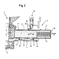
- the structural design of the brush assembly 4 is made FIG. 2 in detail visible.
- the brush assembly 4 consists of a brush sleeve 6, in which a carbon brush 7 is arranged displaceably in the direction of the arrow A.
- the carbon brush 7 is biased by a helical compression spring 8 in the direction of the commutator 9 connected to the rotor 5, wherein the carbon brush 7 applied end of the compression spring 8 is supported on the rear wall 10 of the brush sleeve 6.
- this is displaced by the compression spring 8 in the direction of the commutator 9, whereby the abrasion is compensated until reaching a wear limit.
- the brush sleeve 6 and the housing 2 are each made of a sheet-like, electrically conductive material, for example, brass or steel sheet. These materials have a high strength, but can be easily processed by pressing, stamping or drilling to form complex parts.
- the brush sleeve 6 is undetachably connected via an angle-like projecting leg 11 and a form-fitting manner with a plate-like support member 12 which consists of an electrically non-conductive material and the brush sleeve 6 with respect to the housing 2 electrically insulated.
- the support member 12 in turn is inserted during assembly together with the brush sleeve 6 in the direction of arrow B in the housing 2 integrally formed, tab-like holding means 13 until a protruding from the support member 12 stop 14 abuts the housing 2.
- the holding means are in FIG. 1 also shown in supervision.
- the contact spring 18 of the stator 19 is elastically resilient.
- the contact spring 18 has a relative to the radial surface 17 in the direction of the commutator 9 inclined abutment region 20 which bears against the radial surface 17 under prestress.
- the contact spring 18 is a component to be provided anyway on the electric machine, which in principle can be designed basically unchanged with regard to its shape compared with suitable previously known solutions. In this case, a non-inventively equipped at first installation electrical device can be subsequently provided, for example, in the context of a maintenance operation, with the present invention corresponding catch.
- a circular recess 21 which in trouble-free operation of the electric machine 1 (as well as FIG. 5 apparent) is without function.
- the recess 21 may also have a deviating from the circular contour, which, for example, of a preferred Manufacturing process for the brush sleeve 6 or the shape of the contact spring 18 is affected.
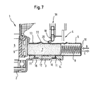
- FIG. 7 consist of the catching means for securing the brush sleeve 6 in its securing position of a protruding from the radial surface 17 of the brush sleeve 6 away from the carbon brush 7 projection 22, which by its ramp-like mounting (arrow B) of the assembly of brush sleeve 6 and support member 12 only slightly impaired, whose displacement in the direction of arrow C, however, sets after reaching the securing position, a considerable resistance.
- basically all components known from the prior art, with the exception of the brush sleeve 6, can be used unchanged, wherein the brush sleeve 6 itself can be produced within the scope of conventional production with the features required for carrying out the invention essentially without additional costs or weight increase is.
Landscapes
- Motor Or Generator Current Collectors (AREA)
Claims (13)
- Agencement de balai (4) sur une machine électrique, notamment sur un appareil ménager électrique, comprenant un manchon de balai (6) logeant le balai de charbon (7), lequel manchon de balai, dans une position d'utilisation, est fixable sur le boîtier (2) de la machine, caractérisé en ce que l'agencement de balai (4) présente des moyens de capture, au moyen desquels le manchon de balai (6) peut être bloqué dans une position de sûreté lorsqu'il quitte la position d'utilisation.
- Agencement de balai selon la revendication 1, caractérisé en ce que les moyens de capture comprennent au moins un dispositif d'enclenchement, lequel saisit par enclenchement le manchon de balai (6) en position de sûreté.
- Agencement de balai selon la revendication 2, caractérisé en ce que le dispositif d'enclenchement présente au moins un évidement (21) ménagé sur la surface radiale (17) du manchon de balai (6), dans lequel évidement s'enclenche un ergot d'arrêt adjacent à la surface radiale en position d'utilisation, lorsque la position de sûreté est obtenue.
- Agencement de balai selon la revendication 3, caractérisé en ce que l'évidement (21) est réalisé de manière circulaire ou rectangulaire, notamment carrée.
- Agencement de balai selon l'une quelconque des revendications 1 à 4, caractérisé en ce que le manchon de balai (6) est réalisé de manière électro-conductrice.
- Agencement de balai selon la revendication 5, caractérisé en ce que l'ergot d'arrêt est formé par le ressort de contact (18) du stator (19).
- Agencement de balai selon la revendication 6, caractérisé en ce que l'évidement (21), en position d'utilisation, est disposé en direction radiale entre le commutateur (9) et le stator (19) de la machine électrique.
- Agencement de balai selon la revendication 7, caractérisé en ce que le ressort de contact (18), en position d'utilisation du manchon de balai (6), est adjacent à la surface radiale (17) du manchon de balai de manière inclinée en direction du commutateur (9).
- Agencement de balai selon l'une quelconque des revendications précédentes, caractérisé en ce que le boîtier (2) de la machine (1) est réalisé de manière électro-conductrice.
- Agencement de balai selon la revendication 9, caractérisé en ce que le manchon de balai (6) est fixé sur une pièce de support (12) isolant électriquement, laquelle, de son côté, est insérable, notamment coulissante, dans des moyens de maintien (13) ménagés sur le boîtier (2).
- Agencement de balai selon la revendication 10, caractérisé en ce que la pièce de support (12) est coulissante dans les moyens de maintien (13) du boîtier (2) en direction du commutateur (9).
- Agencement de balai selon la revendication 1, caractérisé en ce que les moyens de capture comprennent une saillie (22) sur le manchon de balai (6), laquelle, en position de sûreté, bute contre un élément de sûreté, notamment contre le ressort de contact (18).
- Machine électrique (1), notamment appareil ménager électrique, comprenant un agencement de balai (4) selon l'une quelconque des revendications précédentes.
Applications Claiming Priority (2)
| Application Number | Priority Date | Filing Date | Title |
|---|---|---|---|
| DE102007047648A DE102007047648A1 (de) | 2007-10-05 | 2007-10-05 | Bürstenanordnung und elektrische Maschine, insbesondere elektrisches Hausgerät |
| PCT/EP2008/062189 WO2009047083A1 (fr) | 2007-10-05 | 2008-09-12 | Ensemble balai et machine électrique, notamment appareil ménager électrique |
Publications (2)
| Publication Number | Publication Date |
|---|---|
| EP2198490A1 EP2198490A1 (fr) | 2010-06-23 |
| EP2198490B1 true EP2198490B1 (fr) | 2013-05-01 |
Family
ID=39944427
Family Applications (1)
| Application Number | Title | Priority Date | Filing Date |
|---|---|---|---|
| EP08804151.2A Not-in-force EP2198490B1 (fr) | 2007-10-05 | 2008-09-12 | Ensemble balai et machine electrique, notamment appareil menager electrique |
Country Status (8)
| Country | Link |
|---|---|
| US (1) | US20100207483A1 (fr) |
| EP (1) | EP2198490B1 (fr) |
| JP (1) | JP2010541174A (fr) |
| KR (1) | KR20100076993A (fr) |
| CN (1) | CN101816105B (fr) |
| DE (1) | DE102007047648A1 (fr) |
| RU (1) | RU2010114862A (fr) |
| WO (1) | WO2009047083A1 (fr) |
Families Citing this family (6)
| Publication number | Priority date | Publication date | Assignee | Title |
|---|---|---|---|---|
| CN102594035B (zh) * | 2011-01-07 | 2017-05-10 | 德昌电机(深圳)有限公司 | 电机 |
| CN103633525A (zh) * | 2013-11-18 | 2014-03-12 | 宝鸡航天华科机电工业有限公司 | 一种新型电刷 |
| US9601967B2 (en) * | 2014-05-02 | 2017-03-21 | The Scott Fetzer Company | Electric motor brush apparatus and method |
| CN205583897U (zh) * | 2016-03-07 | 2016-09-14 | 德昌电机(深圳)有限公司 | 电刷装置、电机及液泵 |
| CN106654784A (zh) * | 2016-12-20 | 2017-05-10 | 湖南顶立科技有限公司 | 一种平面旋转电刷 |
| CN116608896B (zh) * | 2023-06-30 | 2023-09-19 | 常州华旋传感技术有限公司 | 电机一体式旋转变压器模拟设备及其模拟方法 |
Family Cites Families (10)
| Publication number | Priority date | Publication date | Assignee | Title |
|---|---|---|---|---|
| US3466481A (en) * | 1965-01-30 | 1969-09-09 | Ringsdorff Werke Gmbh | Brush holder with gripping lever for electrical machines |
| US3656018A (en) * | 1970-11-25 | 1972-04-11 | Gen Electric | Brush holder assembly |
| GB1438777A (en) * | 1973-09-04 | 1976-06-09 | Mullard Ltd | Electromechanical propagation devices and the manufacture thereof |
| DE3227199A1 (de) * | 1982-07-21 | 1984-01-26 | Robert Bosch Gmbh, 7000 Stuttgart | Elektromotor, insbesondere zum antreiben von hilfsaggregaten in kraftfahrzeugen |
| CN2098104U (zh) * | 1991-06-17 | 1992-03-04 | 无锡县深硕电器厂 | 供电滑触导管 |
| DE19717594B4 (de) | 1997-04-25 | 2017-09-07 | BSH Hausgeräte GmbH | Bürstenanordnung an einer elektrischen Maschine |
| JPH11234968A (ja) * | 1998-02-12 | 1999-08-27 | Asmo Co Ltd | ブラシ保持装置 |
| JP2003224946A (ja) * | 2002-01-29 | 2003-08-08 | Sanyo Electric Co Ltd | 整流子回転機 |
| GB0328386D0 (en) * | 2003-12-06 | 2004-01-14 | Johnson Electric Sa | Brush holder assembly for an electric motor |
| US7049727B2 (en) * | 2004-01-16 | 2006-05-23 | Robert Bosch Gmbh | Integrated brush-holder retention system |
-
2007
- 2007-10-05 DE DE102007047648A patent/DE102007047648A1/de not_active Withdrawn
-
2008
- 2008-09-12 KR KR1020107009077A patent/KR20100076993A/ko not_active Application Discontinuation
- 2008-09-12 RU RU2010114862/07A patent/RU2010114862A/ru not_active Application Discontinuation
- 2008-09-12 JP JP2010527388A patent/JP2010541174A/ja not_active Withdrawn
- 2008-09-12 US US12/680,905 patent/US20100207483A1/en not_active Abandoned
- 2008-09-12 WO PCT/EP2008/062189 patent/WO2009047083A1/fr active Application Filing
- 2008-09-12 CN CN200880109790XA patent/CN101816105B/zh not_active Expired - Fee Related
- 2008-09-12 EP EP08804151.2A patent/EP2198490B1/fr not_active Not-in-force
Also Published As
| Publication number | Publication date |
|---|---|
| EP2198490A1 (fr) | 2010-06-23 |
| CN101816105A (zh) | 2010-08-25 |
| KR20100076993A (ko) | 2010-07-06 |
| JP2010541174A (ja) | 2010-12-24 |
| CN101816105B (zh) | 2013-01-23 |
| US20100207483A1 (en) | 2010-08-19 |
| WO2009047083A1 (fr) | 2009-04-16 |
| DE102007047648A1 (de) | 2009-04-09 |
| RU2010114862A (ru) | 2011-11-10 |
Similar Documents
| Publication | Publication Date | Title |
|---|---|---|
| EP2198490B1 (fr) | Ensemble balai et machine electrique, notamment appareil menager electrique | |
| EP1921645B1 (fr) | Unité de base avec barre de connexion | |
| DE60114330T2 (de) | Drehverbinder mit Verriegelungsmechanismus zur Gehäuserotationsverhinderung vor dem Einbauen auf das Lenkrad | |
| DE102016116966A1 (de) | Federkraftklemmanschluss sowie Leiteranschlussklemme | |
| EP1536519A1 (fr) | Borne de raccordement pour conducteur | |
| DE102012002145A1 (de) | Hülsenkontakt für einen elektrischen Nullkraftsteckverbinder | |
| DE102017117509A1 (de) | Elektrisches Gerät | |
| WO2016193011A1 (fr) | Système de verrouillage pour un connecteur de charge | |
| WO2016079077A1 (fr) | Borne à ressort | |
| DE102012102810A1 (de) | Scheibenwischermotor und Kohlehalteplatte für einen Scheibenwischermotor | |
| DE102008053137B4 (de) | Steckverbindung, Stromkreis mit Steckverbindung und Betriebsverfahren | |
| WO2008095453A1 (fr) | Appareil électrique et agencement d'appareil | |
| EP2297820B1 (fr) | Dispositif métallique de connexion d un conducteur de protection | |
| EP2409386B1 (fr) | Moteur d'entraînement électrique, en particulier pour un équipement dans un véhicule automobile | |
| EP2696359A1 (fr) | Interrupteur électrique et procédé pour le montage d'un unité de commutation d'un interrupteur | |
| EP3686909A1 (fr) | Appareil d'installation électrique pourvu de douille de socle | |
| DE102016117451B4 (de) | Elektronikgehäuse | |
| DE102018133135A1 (de) | Halterahmen für einen Steckverbinder | |
| EP2543113A2 (fr) | Dispositif de bornes de connexion | |
| DE102021105362A1 (de) | Frontschraubklemme | |
| EP2750269A1 (fr) | Groupe motopompe | |
| DE102019104558A1 (de) | Steckverbinderteil mit einer Rasteinrichtung | |
| EP1627795B1 (fr) | Fixation d'un module de colonne de direction | |
| DE102018205723B4 (de) | Anordnung mit einer Klemmfeder | |
| DE102004058349B3 (de) | Transportsicherung für eine elektrische Maschine sowie elektrische Maschine |
Legal Events
| Date | Code | Title | Description |
|---|---|---|---|
| PUAI | Public reference made under article 153(3) epc to a published international application that has entered the european phase |
Free format text: ORIGINAL CODE: 0009012 |
|
| 17P | Request for examination filed |
Effective date: 20100506 |
|
| AK | Designated contracting states |
Kind code of ref document: A1 Designated state(s): AT BE BG CH CY CZ DE DK EE ES FI FR GB GR HR HU IE IS IT LI LT LU LV MC MT NL NO PL PT RO SE SI SK TR |
|
| AX | Request for extension of the european patent |
Extension state: AL BA MK RS |
|
| DAX | Request for extension of the european patent (deleted) | ||
| GRAP | Despatch of communication of intention to grant a patent |
Free format text: ORIGINAL CODE: EPIDOSNIGR1 |
|
| GRAS | Grant fee paid |
Free format text: ORIGINAL CODE: EPIDOSNIGR3 |
|
| GRAA | (expected) grant |
Free format text: ORIGINAL CODE: 0009210 |
|
| AK | Designated contracting states |
Kind code of ref document: B1 Designated state(s): AT BE BG CH CY CZ DE DK EE ES FI FR GB GR HR HU IE IS IT LI LT LU LV MC MT NL NO PL PT RO SE SI SK TR |
|
| REG | Reference to a national code |
Ref country code: GB Ref legal event code: FG4D Free format text: NOT ENGLISH |
|
| REG | Reference to a national code |
Ref country code: AT Ref legal event code: REF Ref document number: 610440 Country of ref document: AT Kind code of ref document: T Effective date: 20130515 Ref country code: CH Ref legal event code: EP |
|
| REG | Reference to a national code |
Ref country code: IE Ref legal event code: FG4D Free format text: LANGUAGE OF EP DOCUMENT: GERMAN |
|
| REG | Reference to a national code |
Ref country code: DE Ref legal event code: R096 Ref document number: 502008009848 Country of ref document: DE Effective date: 20130627 |
|
| REG | Reference to a national code |
Ref country code: SE Ref legal event code: TRGR |
|
| REG | Reference to a national code |
Ref country code: NL Ref legal event code: VDEP Effective date: 20130501 |
|
| REG | Reference to a national code |
Ref country code: LT Ref legal event code: MG4D |
|
| PG25 | Lapsed in a contracting state [announced via postgrant information from national office to epo] |
Ref country code: PT Free format text: LAPSE BECAUSE OF FAILURE TO SUBMIT A TRANSLATION OF THE DESCRIPTION OR TO PAY THE FEE WITHIN THE PRESCRIBED TIME-LIMIT Effective date: 20130902 Ref country code: IS Free format text: LAPSE BECAUSE OF FAILURE TO SUBMIT A TRANSLATION OF THE DESCRIPTION OR TO PAY THE FEE WITHIN THE PRESCRIBED TIME-LIMIT Effective date: 20130901 Ref country code: NO Free format text: LAPSE BECAUSE OF FAILURE TO SUBMIT A TRANSLATION OF THE DESCRIPTION OR TO PAY THE FEE WITHIN THE PRESCRIBED TIME-LIMIT Effective date: 20130801 Ref country code: ES Free format text: LAPSE BECAUSE OF FAILURE TO SUBMIT A TRANSLATION OF THE DESCRIPTION OR TO PAY THE FEE WITHIN THE PRESCRIBED TIME-LIMIT Effective date: 20130812 Ref country code: FI Free format text: LAPSE BECAUSE OF FAILURE TO SUBMIT A TRANSLATION OF THE DESCRIPTION OR TO PAY THE FEE WITHIN THE PRESCRIBED TIME-LIMIT Effective date: 20130501 Ref country code: GR Free format text: LAPSE BECAUSE OF FAILURE TO SUBMIT A TRANSLATION OF THE DESCRIPTION OR TO PAY THE FEE WITHIN THE PRESCRIBED TIME-LIMIT Effective date: 20130802 Ref country code: SI Free format text: LAPSE BECAUSE OF FAILURE TO SUBMIT A TRANSLATION OF THE DESCRIPTION OR TO PAY THE FEE WITHIN THE PRESCRIBED TIME-LIMIT Effective date: 20130501 Ref country code: LT Free format text: LAPSE BECAUSE OF FAILURE TO SUBMIT A TRANSLATION OF THE DESCRIPTION OR TO PAY THE FEE WITHIN THE PRESCRIBED TIME-LIMIT Effective date: 20130501 |
|
| PG25 | Lapsed in a contracting state [announced via postgrant information from national office to epo] |
Ref country code: BG Free format text: LAPSE BECAUSE OF FAILURE TO SUBMIT A TRANSLATION OF THE DESCRIPTION OR TO PAY THE FEE WITHIN THE PRESCRIBED TIME-LIMIT Effective date: 20130801 Ref country code: CY Free format text: LAPSE BECAUSE OF FAILURE TO SUBMIT A TRANSLATION OF THE DESCRIPTION OR TO PAY THE FEE WITHIN THE PRESCRIBED TIME-LIMIT Effective date: 20130501 Ref country code: HR Free format text: LAPSE BECAUSE OF FAILURE TO SUBMIT A TRANSLATION OF THE DESCRIPTION OR TO PAY THE FEE WITHIN THE PRESCRIBED TIME-LIMIT Effective date: 20130501 Ref country code: PL Free format text: LAPSE BECAUSE OF FAILURE TO SUBMIT A TRANSLATION OF THE DESCRIPTION OR TO PAY THE FEE WITHIN THE PRESCRIBED TIME-LIMIT Effective date: 20130501 |
|
| PG25 | Lapsed in a contracting state [announced via postgrant information from national office to epo] |
Ref country code: LV Free format text: LAPSE BECAUSE OF FAILURE TO SUBMIT A TRANSLATION OF THE DESCRIPTION OR TO PAY THE FEE WITHIN THE PRESCRIBED TIME-LIMIT Effective date: 20130501 |
|
| PG25 | Lapsed in a contracting state [announced via postgrant information from national office to epo] |
Ref country code: SK Free format text: LAPSE BECAUSE OF FAILURE TO SUBMIT A TRANSLATION OF THE DESCRIPTION OR TO PAY THE FEE WITHIN THE PRESCRIBED TIME-LIMIT Effective date: 20130501 Ref country code: CZ Free format text: LAPSE BECAUSE OF FAILURE TO SUBMIT A TRANSLATION OF THE DESCRIPTION OR TO PAY THE FEE WITHIN THE PRESCRIBED TIME-LIMIT Effective date: 20130501 Ref country code: DK Free format text: LAPSE BECAUSE OF FAILURE TO SUBMIT A TRANSLATION OF THE DESCRIPTION OR TO PAY THE FEE WITHIN THE PRESCRIBED TIME-LIMIT Effective date: 20130501 Ref country code: EE Free format text: LAPSE BECAUSE OF FAILURE TO SUBMIT A TRANSLATION OF THE DESCRIPTION OR TO PAY THE FEE WITHIN THE PRESCRIBED TIME-LIMIT Effective date: 20130501 |
|
| PG25 | Lapsed in a contracting state [announced via postgrant information from national office to epo] |
Ref country code: NL Free format text: LAPSE BECAUSE OF FAILURE TO SUBMIT A TRANSLATION OF THE DESCRIPTION OR TO PAY THE FEE WITHIN THE PRESCRIBED TIME-LIMIT Effective date: 20130501 Ref country code: RO Free format text: LAPSE BECAUSE OF FAILURE TO SUBMIT A TRANSLATION OF THE DESCRIPTION OR TO PAY THE FEE WITHIN THE PRESCRIBED TIME-LIMIT Effective date: 20130501 Ref country code: IT Free format text: LAPSE BECAUSE OF FAILURE TO SUBMIT A TRANSLATION OF THE DESCRIPTION OR TO PAY THE FEE WITHIN THE PRESCRIBED TIME-LIMIT Effective date: 20130501 |
|
| PLBE | No opposition filed within time limit |
Free format text: ORIGINAL CODE: 0009261 |
|
| STAA | Information on the status of an ep patent application or granted ep patent |
Free format text: STATUS: NO OPPOSITION FILED WITHIN TIME LIMIT |
|
| BERE | Be: lapsed |
Owner name: BSH BOSCH UND SIEMENS HAUSGERATE G.M.B.H. Effective date: 20130930 |
|
| 26N | No opposition filed |
Effective date: 20140204 |
|
| PG25 | Lapsed in a contracting state [announced via postgrant information from national office to epo] |
Ref country code: MC Free format text: LAPSE BECAUSE OF FAILURE TO SUBMIT A TRANSLATION OF THE DESCRIPTION OR TO PAY THE FEE WITHIN THE PRESCRIBED TIME-LIMIT Effective date: 20130501 |
|
| REG | Reference to a national code |
Ref country code: CH Ref legal event code: PL |
|
| REG | Reference to a national code |
Ref country code: DE Ref legal event code: R097 Ref document number: 502008009848 Country of ref document: DE Effective date: 20140204 |
|
| REG | Reference to a national code |
Ref country code: IE Ref legal event code: MM4A |
|
| PG25 | Lapsed in a contracting state [announced via postgrant information from national office to epo] |
Ref country code: IE Free format text: LAPSE BECAUSE OF NON-PAYMENT OF DUE FEES Effective date: 20130912 Ref country code: CH Free format text: LAPSE BECAUSE OF NON-PAYMENT OF DUE FEES Effective date: 20130930 Ref country code: LI Free format text: LAPSE BECAUSE OF NON-PAYMENT OF DUE FEES Effective date: 20130930 Ref country code: BE Free format text: LAPSE BECAUSE OF NON-PAYMENT OF DUE FEES Effective date: 20130930 |
|
| REG | Reference to a national code |
Ref country code: AT Ref legal event code: MM01 Ref document number: 610440 Country of ref document: AT Kind code of ref document: T Effective date: 20130912 |
|
| PG25 | Lapsed in a contracting state [announced via postgrant information from national office to epo] |
Ref country code: AT Free format text: LAPSE BECAUSE OF NON-PAYMENT OF DUE FEES Effective date: 20130912 |
|
| REG | Reference to a national code |
Ref country code: DE Ref legal event code: R081 Ref document number: 502008009848 Country of ref document: DE Owner name: BSH HAUSGERAETE GMBH, DE Free format text: FORMER OWNER: BSH BOSCH UND SIEMENS HAUSGERAETE GMBH, 81739 MUENCHEN, DE Effective date: 20150408 |
|
| PG25 | Lapsed in a contracting state [announced via postgrant information from national office to epo] |
Ref country code: MT Free format text: LAPSE BECAUSE OF FAILURE TO SUBMIT A TRANSLATION OF THE DESCRIPTION OR TO PAY THE FEE WITHIN THE PRESCRIBED TIME-LIMIT Effective date: 20130501 |
|
| PG25 | Lapsed in a contracting state [announced via postgrant information from national office to epo] |
Ref country code: LU Free format text: LAPSE BECAUSE OF NON-PAYMENT OF DUE FEES Effective date: 20130912 Ref country code: HU Free format text: LAPSE BECAUSE OF FAILURE TO SUBMIT A TRANSLATION OF THE DESCRIPTION OR TO PAY THE FEE WITHIN THE PRESCRIBED TIME-LIMIT; INVALID AB INITIO Effective date: 20080912 |
|
| REG | Reference to a national code |
Ref country code: FR Ref legal event code: PLFP Year of fee payment: 8 |
|
| REG | Reference to a national code |
Ref country code: FR Ref legal event code: CD Owner name: BSH HAUSGERATE GMBH, DE Effective date: 20151022 |
|
| REG | Reference to a national code |
Ref country code: FR Ref legal event code: PLFP Year of fee payment: 9 |
|
| REG | Reference to a national code |
Ref country code: FR Ref legal event code: PLFP Year of fee payment: 10 |
|
| REG | Reference to a national code |
Ref country code: FR Ref legal event code: PLFP Year of fee payment: 11 |
|
| PGFP | Annual fee paid to national office [announced via postgrant information from national office to epo] |
Ref country code: FR Payment date: 20180921 Year of fee payment: 11 |
|
| PGFP | Annual fee paid to national office [announced via postgrant information from national office to epo] |
Ref country code: GB Payment date: 20180924 Year of fee payment: 11 Ref country code: TR Payment date: 20180828 Year of fee payment: 11 Ref country code: SE Payment date: 20180924 Year of fee payment: 11 |
|
| PG25 | Lapsed in a contracting state [announced via postgrant information from national office to epo] |
Ref country code: SE Free format text: LAPSE BECAUSE OF NON-PAYMENT OF DUE FEES Effective date: 20190913 |
|
| REG | Reference to a national code |
Ref country code: SE Ref legal event code: EUG |
|
| GBPC | Gb: european patent ceased through non-payment of renewal fee |
Effective date: 20190912 |
|
| PG25 | Lapsed in a contracting state [announced via postgrant information from national office to epo] |
Ref country code: GB Free format text: LAPSE BECAUSE OF NON-PAYMENT OF DUE FEES Effective date: 20190912 Ref country code: FR Free format text: LAPSE BECAUSE OF NON-PAYMENT OF DUE FEES Effective date: 20190930 |
|
| PG25 | Lapsed in a contracting state [announced via postgrant information from national office to epo] |
Ref country code: TR Free format text: LAPSE BECAUSE OF NON-PAYMENT OF DUE FEES Effective date: 20190912 |
|
| PGFP | Annual fee paid to national office [announced via postgrant information from national office to epo] |
Ref country code: DE Payment date: 20220930 Year of fee payment: 15 |
|
| P01 | Opt-out of the competence of the unified patent court (upc) registered |
Effective date: 20230504 |
|
| REG | Reference to a national code |
Ref country code: DE Ref legal event code: R119 Ref document number: 502008009848 Country of ref document: DE |
|
| PG25 | Lapsed in a contracting state [announced via postgrant information from national office to epo] |
Ref country code: DE Free format text: LAPSE BECAUSE OF NON-PAYMENT OF DUE FEES Effective date: 20240403 |