EP2197813B1 - Keramischer schichtverbund - Google Patents
Keramischer schichtverbund Download PDFInfo
- Publication number
- EP2197813B1 EP2197813B1 EP08837017.6A EP08837017A EP2197813B1 EP 2197813 B1 EP2197813 B1 EP 2197813B1 EP 08837017 A EP08837017 A EP 08837017A EP 2197813 B1 EP2197813 B1 EP 2197813B1
- Authority
- EP
- European Patent Office
- Prior art keywords
- ceramic layer
- ceramic
- layer
- specific surface
- large specific
- Prior art date
- Legal status (The legal status is an assumption and is not a legal conclusion. Google has not performed a legal analysis and makes no representation as to the accuracy of the status listed.)
- Not-in-force
Links
Images
Classifications
-
- C—CHEMISTRY; METALLURGY
- C04—CEMENTS; CONCRETE; ARTIFICIAL STONE; CERAMICS; REFRACTORIES
- C04B—LIME, MAGNESIA; SLAG; CEMENTS; COMPOSITIONS THEREOF, e.g. MORTARS, CONCRETE OR LIKE BUILDING MATERIALS; ARTIFICIAL STONE; CERAMICS; REFRACTORIES; TREATMENT OF NATURAL STONE
- C04B41/00—After-treatment of mortars, concrete, artificial stone or ceramics; Treatment of natural stone
- C04B41/45—Coating or impregnating, e.g. injection in masonry, partial coating of green or fired ceramics, organic coating compositions for adhering together two concrete elements
- C04B41/50—Coating or impregnating, e.g. injection in masonry, partial coating of green or fired ceramics, organic coating compositions for adhering together two concrete elements with inorganic materials
- C04B41/5025—Coating or impregnating, e.g. injection in masonry, partial coating of green or fired ceramics, organic coating compositions for adhering together two concrete elements with inorganic materials with ceramic materials
-
- C—CHEMISTRY; METALLURGY
- C04—CEMENTS; CONCRETE; ARTIFICIAL STONE; CERAMICS; REFRACTORIES
- C04B—LIME, MAGNESIA; SLAG; CEMENTS; COMPOSITIONS THEREOF, e.g. MORTARS, CONCRETE OR LIKE BUILDING MATERIALS; ARTIFICIAL STONE; CERAMICS; REFRACTORIES; TREATMENT OF NATURAL STONE
- C04B41/00—After-treatment of mortars, concrete, artificial stone or ceramics; Treatment of natural stone
- C04B41/009—After-treatment of mortars, concrete, artificial stone or ceramics; Treatment of natural stone characterised by the material treated
-
- C—CHEMISTRY; METALLURGY
- C04—CEMENTS; CONCRETE; ARTIFICIAL STONE; CERAMICS; REFRACTORIES
- C04B—LIME, MAGNESIA; SLAG; CEMENTS; COMPOSITIONS THEREOF, e.g. MORTARS, CONCRETE OR LIKE BUILDING MATERIALS; ARTIFICIAL STONE; CERAMICS; REFRACTORIES; TREATMENT OF NATURAL STONE
- C04B41/00—After-treatment of mortars, concrete, artificial stone or ceramics; Treatment of natural stone
- C04B41/45—Coating or impregnating, e.g. injection in masonry, partial coating of green or fired ceramics, organic coating compositions for adhering together two concrete elements
- C04B41/52—Multiple coating or impregnating multiple coating or impregnating with the same composition or with compositions only differing in the concentration of the constituents, is classified as single coating or impregnation
- C04B41/526—Multiple coating or impregnation with materials having the same composition but different characteristics
-
- C—CHEMISTRY; METALLURGY
- C04—CEMENTS; CONCRETE; ARTIFICIAL STONE; CERAMICS; REFRACTORIES
- C04B—LIME, MAGNESIA; SLAG; CEMENTS; COMPOSITIONS THEREOF, e.g. MORTARS, CONCRETE OR LIKE BUILDING MATERIALS; ARTIFICIAL STONE; CERAMICS; REFRACTORIES; TREATMENT OF NATURAL STONE
- C04B41/00—After-treatment of mortars, concrete, artificial stone or ceramics; Treatment of natural stone
- C04B41/80—After-treatment of mortars, concrete, artificial stone or ceramics; Treatment of natural stone of only ceramics
- C04B41/81—Coating or impregnation
- C04B41/85—Coating or impregnation with inorganic materials
- C04B41/87—Ceramics
-
- C—CHEMISTRY; METALLURGY
- C04—CEMENTS; CONCRETE; ARTIFICIAL STONE; CERAMICS; REFRACTORIES
- C04B—LIME, MAGNESIA; SLAG; CEMENTS; COMPOSITIONS THEREOF, e.g. MORTARS, CONCRETE OR LIKE BUILDING MATERIALS; ARTIFICIAL STONE; CERAMICS; REFRACTORIES; TREATMENT OF NATURAL STONE
- C04B41/00—After-treatment of mortars, concrete, artificial stone or ceramics; Treatment of natural stone
- C04B41/80—After-treatment of mortars, concrete, artificial stone or ceramics; Treatment of natural stone of only ceramics
- C04B41/81—Coating or impregnation
- C04B41/89—Coating or impregnation for obtaining at least two superposed coatings having different compositions
-
- F—MECHANICAL ENGINEERING; LIGHTING; HEATING; WEAPONS; BLASTING
- F23—COMBUSTION APPARATUS; COMBUSTION PROCESSES
- F23Q—IGNITION; EXTINGUISHING-DEVICES
- F23Q7/00—Incandescent ignition; Igniters using electrically-produced heat, e.g. lighters for cigarettes; Electrically-heated glowing plugs
- F23Q7/001—Glowing plugs for internal-combustion engines
-
- C—CHEMISTRY; METALLURGY
- C04—CEMENTS; CONCRETE; ARTIFICIAL STONE; CERAMICS; REFRACTORIES
- C04B—LIME, MAGNESIA; SLAG; CEMENTS; COMPOSITIONS THEREOF, e.g. MORTARS, CONCRETE OR LIKE BUILDING MATERIALS; ARTIFICIAL STONE; CERAMICS; REFRACTORIES; TREATMENT OF NATURAL STONE
- C04B2111/00—Mortars, concrete or artificial stone or mixtures to prepare them, characterised by specific function, property or use
- C04B2111/00241—Physical properties of the materials not provided for elsewhere in C04B2111/00
- C04B2111/00405—Materials with a gradually increasing or decreasing concentration of ingredients or property from one layer to another
-
- F—MECHANICAL ENGINEERING; LIGHTING; HEATING; WEAPONS; BLASTING
- F23—COMBUSTION APPARATUS; COMBUSTION PROCESSES
- F23Q—IGNITION; EXTINGUISHING-DEVICES
- F23Q7/00—Incandescent ignition; Igniters using electrically-produced heat, e.g. lighters for cigarettes; Electrically-heated glowing plugs
- F23Q7/001—Glowing plugs for internal-combustion engines
- F23Q2007/004—Manufacturing or assembling methods
Definitions
- the present invention is based on a ceramic layer composite according to the preamble of claim 1. Furthermore, the application relates to a method for producing a ceramic layer composite.
- US 2006/0246319 A1 refers to a shock-resistant multi-layer coating.
- a component for a turbine includes a ceramic substrate having a surface, a barrier layer bonded to the substrate surface, and an impact resistant layer bonded to the barrier layer.
- the impact resistant layer has a porosity of between 10% and 30%.
- the impact resistant layer, the barrier layer and the areas where the layers are bonded to the substrate surface have a higher shear capacity than the substrate.
- EP 1 544 185 A2 refers to a coating having an upper layer that reduces the velocity of a gas stream.
- a composite having a silicon-based substrate comprises a topsheet that effects a velocity reduction of a gas stream. This reduces the stress on components that would otherwise be associated with an unrestrained gas flow.
- the velocity reducing layer reduces the velocity of an incident gas stream by at least 50% across the thickness of the velocity reduction layer.
- EP 1 394 138 A2 refers to a protective layer for ceramics.
- a ceramic matrix composite is protected by an aluminum protective layer of high temperatures and a humidity-containing environment.
- the protective topcoat comprises aluminum to protect an underlying monolithic layer from temperatures in excess of 1500 ° C.
- the porosity of the coating is more than 15%, resulting in improved thermal shock properties.
- US 2003/0138641 A1 refers to corrosion-resistant Kermiken. These include a substrate such as silicon nitride, silicon carbide. There is provided a surface protective layer comprising zirconia stabilized with an element of Group IIIA of the Periodic Table. The aluminum and silicon content in the surface protective layer is not more than 1% by mass. In particular, the surface layer has a thickness of between 5 mm and 200 mm and a porosity of between 5% and 30%.
- the anti-corrosion ceramic has a high resistance to corrosion and a temperature range of below 1000 ° C.
- WO 2007/056876 A1 refers to a process for producing a porous ceramic thin film.
- a solution or a suspension of an organic and / or inorganic metal composite as the starting material is admixed with a mixed, non-soluble pore-forming agent.
- the mixture is sprayed on as a layer of a thin film and the pore-forming agent is at least partially thermally decomposed or burnt out to form an at least partially open-pored structure.
- US 5,578,349 A refers to a method of coating a ceramic glow plug with a corrosion resistant material.
- a uniformly adherent tantalum oxide coating is applied to a portion of a ceramic glow plug, thereby protecting the glow plug from a corrosive or erosive environment created by combustion of alternative fuels in a diesel engine.
- the coating is a tantalum oxide which is applied to a silicon nitride glow plug by plasma spray deposition.
- DE 10 2005 062 115 A1 refers to an incandescent, ignition or heating element for combustion and / or heating devices.
- a corrosion protection layer is disclosed for silicon-containing ceramic parts of the annealing, ignition or heating element. This is characterized in that the corrosion protection layer is composed of a mixture of SiO 2 and at least one other substance.
- non-oxide ceramics are characterized by a higher proportion of covalent bonds. These allow high chemical and thermal stability due to the strong binding energies, provide a high modulus of elasticity and give great strength and hardness. At the same time, however, they show lower ductility and rather high brittleness.
- silicon nitride ceramics are used for machine components with very high dynamic loads and reliability requirements. In addition, these are suitable as high-temperature material. Examples of applications of silicon nitride ceramics are glow plugs in internal combustion engines, heating elements, products in metalworking with cutting materials (indexable inserts), the rolling bearing technology with balls, rollers and rings and highly stressed machine elements in engine or turbine construction.
- a suitable measure for corrosion protection is the coating of the non-oxide ceramic with a further ceramic layer.
- adhesive bonds with which ceramics can be connected to each other are only limited thermal load and therefore entirely unsuitable for high temperature application.
- a ceramic layer composite formed according to the invention comprises a ceramic substrate made of a non-oxide ceramic to which a ceramic layer has been applied.
- the ceramic layer has a large specific surface area.
- a large specific surface in the sense of the present invention means a specific surface area in the range of 10 to 350 m 2 / g.
- the ceramic layer acts with the large specific surface area as an evaporation layer. Liquid impinging on the ceramic layer composite vaporizes on the evaporation layer and preferably forms a vaporous layer. This vaporous layer prevents the impact of a cold jet of fuel during the injection of fuel into the internal combustion engine and the associated thermal shock.
- the vaporous layer acts as an insulating layer.
- Suitable non-oxide ceramics that can be used for the ceramic substrate are, for example, silicon nitride, silicon carbide and aluminum nitride.
- non-oxide ceramic according to the invention also non-oxide ceramic materials understood that can be doped or offset with one or more additives.
- the additives may for example be selected from the group Al 2 O 3 , MgO, Yb 2 O 3 , Y 2 O 3 and other rare earth oxides, which are used for example as sintering additives in the preparation. With such additives, the properties of the ceramic material can be influenced and improved. Such material systems have proven particularly suitable for high-temperature applications.
- silicon nitride is particularly preferred as a non-oxide ceramic, as this has a combination of excellent material properties that can meet the most extreme conditions of use has.
- silicon nitride is suitable for use in high temperature applications, e.g. for glow plugs. With glow plugs, the ceramic substrate is generally heated to a temperature of up to 1400 ° C.
- silicon nitride shows a good thermal shock resistance, as occurs especially in glow plugs by the impact of the cold fuel jet.
- silicon nitride tends to corrode in the presence of aggressive media, it is necessary to protect the silicon nitride against corrosion. This is done by applying a ceramic layer with low porosity, which acts as a corrosion protection layer. This ceramic layer is disposed between the ceramic substrate and the ceramic layer having the large specific surface area.
- a low porosity in the sense of the present invention means that the pore volume is smaller than 10%.
- the ceramic layer with the low porosity which acts as a corrosion protection layer, is preferably a chemically bonded ceramic layer of Al 2 O 3 , AlN, rare earth silicates such as Yb 2 O 3 * SiO 2 or Y 2 O 3 * SiO 2 , rare earth oxides, Si 3 N 4 , mullite, cordierite or aluminosilicates.
- the term chemically bound is understood according to the invention as that ionic and / or covalent bonds are formed between the layers.
- the layer may also be mechanically bonded to the substrate.
- the additional chemical bonding of the ceramic layer with low porosity offers over a purely mechanical connection and physical interactions the advantage that a disruption of the connection between the substrate and the ceramic layer with low porosity requires significantly more energy and crack propagation in the ceramic structure can be significantly delayed .
- the compound may preferably be designed such that in the transition from the substrate surface to the ceramic layer with the low porosity, a sliding adaptation of thermal expansion and elastic constants is achieved.
- the inventive generation of a flowing transition in the material properties the spalling of the corrosion protection layer can be prevented. This allows a significantly improved wear resistance and extended durability of the substrate.
- the ceramic material of the ceramic layer with the low porosity is additionally preferably selected so that the material properties are as similar as possible to the material properties of the ceramic substrate.
- the thermal expansion coefficients of the substrate material and the ceramic layer with the low porosity are preferably in a narrow range with each other. This selection prevents excessive stress between layers, especially during frequent and extreme thermal cycling loads. In this way, gradient ceramic composite systems can be provided which have high strength and excellent thermal shock resistance.
- the thickness of the low-porosity ceramic layer is preferably in the range of 2 ⁇ m to 1 mm, more preferably 2 ⁇ m to 100 ⁇ m.
- At least one further ceramic layer is present between the substrate surface and the ceramic layer with the low porosity.
- the further ceramic layers which are contained between the substrate surface and the ceramic layer with the low porosity, are preferably also chemically bonded to the respectively underlying ceramic layer. At the same time, there may also be a mechanical connection to the underlying layer.
- the at least one ceramic layer sandwiched between the substrate surface and the low porosity ceramic layer may be made of the same or different ceramic material as the low porosity ceramic layer.
- the further ceramic layer can, in a preferred embodiment, as an adhesion-promoting layer between the ceramic substrate and the low porosity ceramic layer.
- the further ceramic layer the corrosion resistance of the substrate can be significantly increased again.
- the at least one further ceramic layer may have a thickness in the range from 2 ⁇ m to 1 mm, preferably from 20 ⁇ m to 100 ⁇ m.
- the ceramic layer having the large specific surface area may in one embodiment be made thicker than the first ceramic layer.
- the at least one further ceramic layer preferably likewise acts as a corrosion protection layer.
- the sequence of layers from the substrate to the ceramic layer with the large specific surface area is designed such that an optimum gradient in the material properties results at the transitions of the layers, in particular in the thermal expansion coefficients. Flowing transitions in the material properties can prevent or at least reduce stresses between the ceramic layers and spalling of the individual ceramic layers.
- the ceramic layer composite thus has excellent corrosion and wear resistance.
- the smooth transition in material properties is achieved by making the low porosity ceramic layer and the large specific surface ceramic layer of the same ceramic.
- the process properties during application of the ceramic be changed such that the layer initially has a low porosity and then the parameters are changed such that the specific surface is gradually increased.
- plasma spraying processes are suitable for this purpose.
- Advantage of using a same ceramic for the ceramic layer with the low porosity and the ceramic layer with the large specific surface is that they have the same material properties, in particular the same coefficient of thermal expansion.
- Suitable ceramics for the ceramic layer having the high surface area are, for example, mullite, a rare earth silicate, for example, Y 2 O 3 * SiO 2 or Yb 2 O 3 * SiO 2 , cordierite, an aluminosilicate, aluminum nitride, alumina, or mixtures thereof
- Preferred materials for the ceramic layer with the large specific Surface are mullite or a rare earth silicate.
- the ceramic layer is porous.
- the porosity of the layer is adjusted such that it enables optimum evaporation with regard to the components of the impinging fuel when the ceramic layer composite is used in a glow plug.
- the setting of the porosity is generally carried out by a selective deposition of the ceramic on the surface to be coated or by incorporation of, for example, polymer particles which are burned out after coating from the ceramic.
- the ceramic layer with the large specific surface contains recesses on its surface or is applied in the form of a microstructure.
- the recesses on the surface or the applied microstructure also increase the specific surface area.
- the pits or microstructure are e.g. generated by a laser treatment.
- the ceramic layer with the large specific surface is applied by a plasma spray process, a suspension plasma process, a CVD (Chemical Vapor Deposition) or PVD (Physical Vapor Deposition) method or by applying a sol-gel suspension and subsequent thermal treatment ,
- a plasma spray process a suspension plasma process
- CVD Chemical Vapor Deposition
- PVD Physical Vapor Deposition
- the advantage of the plasma spraying process, the suspension plasma process, the CVD or PVD process is that these can be used to set a surface structure of the ceramic layer with the large specific surface in a targeted manner.
- the suspension When applying the ceramic layer with the large specific surface area by means of a sol-gel suspension, the suspension preferably also contains polymer particles which are burned out of the layer during the thermal treatment in order to produce pores in the second ceramic layer.
- the application of the ceramic layer with the large specific surface area preferably takes place with the aid of the plasma spraying process.
- plasma spraying process Both an atmospheric plasma spraying process (APS) and plasma spraying under vacuum can be used here.
- Argon or helium are preferably used as the plasma gas. These can additionally be selectively added a reducing gas.
- Preferred as the reducing gas is hydrogen.
- the proportion of hydrogen is preferably less than 5% by volume.
- an oxide layer possibly present on the substrate surface can first be removed.
- a roughening and cleansing pretreatment of the substrate surface can take place, for example, by irradiation with small particles. Preferably, this is done with small particles under low pressure to reduce or avoid defects and damage to the substrate.
- the application of the ceramic layer with the low porosity is preferably carried out by an atmospheric plasma spray process (APS) on the surface of the ceramic substrate.
- APS atmospheric plasma spray process
- a ceramic layer can be applied to the substrate.
- any metallic or ceramic materials which form a ceramic layer on the substrate or can be converted into such a ceramic layer can be added to the plasma gas as powdered coating additive.
- These are, for example, aluminum powder which can be converted into AlN by nitration with nitrogen, Al 2 O 3 , Si 3 N 4 , cordierite, mullite, rare earth silicates or aluminosilicates.
- the coating additive for the ceramic layer with low porosity is preferably selected so that the resulting ceramic layer has as similar as possible a material properties, in particular a similar thermal expansion coefficient, to the ceramic material of the substrate.
- the coating additive for the ceramic layer with the large specific surface area is selected according to the invention such that the resulting ceramic layer has as similar as possible a material properties to the ceramic layer with the low porosity.
- the large specific surface area required for the large specific surface ceramic layer can be achieved, for example, by roughening or by selectively applying a microstructure.
- the ceramic of the ceramic layer having the large specific surface area particles are contained in the coating material, which are removed after the application to produce pores in the second ceramic layer.
- the removal of the particles can be carried out, for example, by dissolving out the particles from the ceramic, if they are soluble in a solvent.
- the substrate is heated before or during coating with the low porosity ceramic layer or the large specific surface ceramic layer.
- the substrate is heated above the crystallization temperature of the coating material.
- the further ceramic layer can also act as a primer layer for the application of the ceramic layer with low porosity.
- the ceramic layer with the low porosity may be thicker than the chemically bonded further ceramic layer. As a result, the corrosion resistance of the substrate can be further improved.
- the ceramic composite layer according to the invention preferably for the production of glow plugs, such as those in internal combustion engines , in particular self-igniting internal combustion engines, are used.
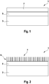
- FIG. 1 a ceramic layer composite formed according to the invention is shown in a first embodiment.
- a ceramic layer composite 1 comprises a ceramic substrate 3 made of a non-oxide ceramic.
- the substrate 3 is made of a silicon nitride (Si 3 N 4 ) ceramic.
- Si 3 N 4 silicon nitride
- the advantage of silicon nitride ceramics is that it has material properties which also allow use of the layer composite under extreme conditions. In particular, use under high temperatures.
- silicon nitride As an alternative to silicon nitride, however, it is also possible to use BN, TiN, TiAlN, AlN, sialone, SiC. However, preferred is silicon nitride.
- non-oxide ceramic also includes non-oxide kermic materials which may be doped or offset with one or more additives.
- additives may for example be selected from the group Al 2 O 3 , MgO, Yb 2 O 3 , Y 2 O 3 and other rare earth oxides, which are used for example as sintering additives in the preparation.
- the ceramic layer 5 is characterized by a low porosity.
- the low-porosity ceramic layer 5 is preferably applied by an atmospheric plasma spray process.
- a gas flow high-energy plasma, an ionized and dissociated gas generated at a temperature of about 12000 K the coating material is supplied in powder form, directed to the substrate 3 to be coated.
- the powdery coating material melts and is thrown by the gas stream on the surface of the coating material, where it solidifies immediately. Due to the extreme temperatures, almost all materials, such as metal powder and also high-melting ceramic powders can be used as coating material.
- the method is particularly suitable for the production of hard protective layers with a defined thickness. Usually, the process is carried out at atmospheric pressure. However, it is also possible to carry out the process in vacuo or under protective gas.
- a ceramic layer 7 with the large specific surface is applied to the ceramic layer 5 with low porosity.
- the large specific surface area can be achieved, for example, by making the ceramic layer 7, as shown in FIG. 1, porous.
- the porosity is achieved, for example, by selectively applying a porous layer 7 to the ceramic layer 5 with low porosity.
- the porosity can be adjusted, for example, by applying placeholders with the coating material.
- the placeholders are removed from the ceramic layer 7 after forming the second ceramic layer. The removal takes place, for example, by dissolution or burnout. Burning out is possible in particular when the particles which fill the pores have a lower flash point than the material of the ceramic layer 7.
- the application of the ceramic layer 7 with the large specific surface is preferably carried out by a plasma spray process.
- the ceramic particles are applied selectively to the ceramic layer 5 with low porosity.
- a desired porosity is already set during application of the ceramic layer 7.
- Another alternative is to apply the ceramic layer 7 with the large specific surface area as a sol-gel suspension and then to treat it thermally.
- particles are added to the suspension to be applied.
- This can for Example be spherical particles.
- the particles are preferably made of a material which decomposes thermally even at low temperatures. Suitable materials are, for example, polymers.
- the particles are burned out after the application of the suspension from the coating. As a result, a defined porosity is produced in the ceramic layer 7 with the large specific surface area.
- FIG. 2 a ceramic layer composite is shown in a second embodiment.
- the in FIG. 2 illustrated ceramic layer composite 1 differs from the ceramic layer composite 1 shown in Figure 1 in that a ceramic layer 7 is applied with a large specific surface in the form of a microstructure 9 on the ceramic layer 5 with the low porosity.
- the microstructure 9 is, for example, acicular as shown here. However, any other geometry of the microstructure 9 is also conceivable.
- a needle-shaped structure can be produced, for example, by targeted application of the coating material in a plasma spray process.
- Suitable materials include mullite, rare earth silicates, for example Y 2 O 3 * SiO 2 or Yb 2 O 3 * SiO 2 , cordierite, aluminosilicate, aluminum nitride, aluminum oxide or mixtures thereof. Particularly suitable is mullite.
- the surface of the ceramic layer 7 with the large specific surface by inserting recesses into it.
- the depressions can take any shape. It is preferred if the depressions are produced by a laser treatment of the surface of the ceramic layer 7 with the large specific surface area. However, it is also possible if the recesses are introduced in the form of holes in the ceramic layer 7 with the large specific surface area.
- the coating according to the invention protects the ceramic substrate 3 against both corrosion and thermal shocks.
- the ceramic layer 5 with low porosity acts as a corrosion protection layer. This preserves the ceramic material of the substrate 3 from oxidation.
- the ceramic layer 7 having the large specific surface acts as an evaporation layer. At this impinging liquids evaporate and form a vapor layer. This serves as additional insulation, so that no cold liquid can impinge on the substrate 3.
- the substrate 3 and the ceramic layer 5 with low porosity at least one further ceramic layer is applied.
- the at least one further ceramic layer preferably likewise has a low porosity and thus acts as a corrosion protection layer.
- the material for the further ceramic layers which may be accommodated between the substrate 3 and the low porosity ceramic layer 5 is preferably the same as the material for the low porosity ceramic layer 5.
- the inventive ceramic layer composite 1 is preferably used for high-temperature applications in corrosive environments. Such applications are, for example, glow plugs in auto-igniting internal combustion engines.
Landscapes
- Chemical & Material Sciences (AREA)
- Engineering & Computer Science (AREA)
- Ceramic Engineering (AREA)
- Materials Engineering (AREA)
- Structural Engineering (AREA)
- Organic Chemistry (AREA)
- Inorganic Chemistry (AREA)
- Combustion & Propulsion (AREA)
- Mechanical Engineering (AREA)
- General Engineering & Computer Science (AREA)
- Other Surface Treatments For Metallic Materials (AREA)
- Coating By Spraying Or Casting (AREA)
- Laminated Bodies (AREA)
- Physical Vapour Deposition (AREA)
Applications Claiming Priority (2)
| Application Number | Priority Date | Filing Date | Title |
|---|---|---|---|
| DE102007047590A DE102007047590A1 (de) | 2007-10-05 | 2007-10-05 | Keramischer Schichtverbund sowie Verfahren zu seiner Herstellung |
| PCT/EP2008/062411 WO2009047096A1 (de) | 2007-10-05 | 2008-09-18 | Keramischer schichtverbund sowie verfahren zu seiner herstellung |
Publications (2)
| Publication Number | Publication Date |
|---|---|
| EP2197813A1 EP2197813A1 (de) | 2010-06-23 |
| EP2197813B1 true EP2197813B1 (de) | 2018-07-11 |
Family
ID=40243998
Family Applications (1)
| Application Number | Title | Priority Date | Filing Date |
|---|---|---|---|
| EP08837017.6A Not-in-force EP2197813B1 (de) | 2007-10-05 | 2008-09-18 | Keramischer schichtverbund |
Country Status (5)
| Country | Link |
|---|---|
| EP (1) | EP2197813B1 (ja) |
| JP (1) | JP5300851B2 (ja) |
| CN (1) | CN101815690A (ja) |
| DE (1) | DE102007047590A1 (ja) |
| WO (1) | WO2009047096A1 (ja) |
Families Citing this family (9)
| Publication number | Priority date | Publication date | Assignee | Title |
|---|---|---|---|---|
| DE102009037183B4 (de) | 2009-08-12 | 2012-03-22 | Bayerische Motoren Werke Aktiengesellschaft | Verfahren zur Herstellung eines Formteils, insbesondere eines Bedienteils für den Fahrgastraum eines Kraftfahrzeugs |
| DE102009028952A1 (de) * | 2009-08-27 | 2011-03-03 | Robert Bosch Gmbh | Glühkerze mit integriertem Temperaturfühler |
| DE102014104886A1 (de) | 2014-04-07 | 2015-10-08 | Mas Gmbh | Schneidplatte, Zerspanungswerkzeug und Verfahren zur Herstellung einer Schneidplatte |
| CN105156251A (zh) * | 2015-08-27 | 2015-12-16 | 扬州市飞鹰电子科技有限公司 | 一种柴油发动机氧化物陶瓷电热塞及其生产方法 |
| DE102016104509B3 (de) * | 2016-03-11 | 2017-08-03 | Ks Gleitlager Gmbh | Metall/Kunststoff-Gleitlagerverbundwerkstoff und hieraus hergestelltes Gleitlagerelement |
| DE102019207367A1 (de) * | 2019-05-20 | 2020-11-26 | Oerlikon Surface Solutions Ag | Verfahren zum Aufbringen einer Beschichtung auf eine Oberfläche eines Mullitmaterials, Mullitmaterial mit einer Beschichtung und Gasturbinenbauteil |
| CN111792946A (zh) * | 2020-06-22 | 2020-10-20 | 季华实验室 | 一种陶瓷基体表面处理方法 |
| CN113860881A (zh) * | 2021-10-12 | 2021-12-31 | 中山大学 | 相转化法制备纤维独石结构氮化硅陶瓷材料 |
| CN116410018A (zh) * | 2021-12-31 | 2023-07-11 | 江苏博睿光电股份有限公司 | 一种基板、制备方法及应用 |
Family Cites Families (9)
| Publication number | Priority date | Publication date | Assignee | Title |
|---|---|---|---|---|
| US5578349A (en) * | 1995-11-30 | 1996-11-26 | Caterpillar Inc. | Process for coating a ceramic glow plug portion with a corrosion inhibiting material |
| JP3785698B2 (ja) * | 1996-09-11 | 2006-06-14 | 株式会社デンソー | グロープラグ |
| US6682821B2 (en) * | 2001-12-28 | 2004-01-27 | Kyocera Corporation | Corrosion-resistant ceramics |
| US6929852B2 (en) * | 2002-08-08 | 2005-08-16 | Siemens Westinghouse Power Corporation | Protective overlayer for ceramics |
| US20050129973A1 (en) * | 2003-12-16 | 2005-06-16 | Eaton Harry E. | Velocity barrier layer for environmental barrier coatings |
| US20060246319A1 (en) * | 2005-05-02 | 2006-11-02 | Honeywell International, Inc. | Impact-resistant multilayer coating |
| ATE451338T1 (de) * | 2005-11-21 | 2009-12-15 | Eidgenoess Tech Hochschule | Verfahren zur herstellung eines porösen keramischen dünnfilms |
| DE102005062115A1 (de) * | 2005-12-23 | 2007-06-28 | Robert Bosch Gmbh | Glüh-, Zünd- oder Heizelement für Verbrennungs- und/oder Heizvorrichtungen |
| DE102006044775A1 (de) * | 2006-09-22 | 2008-04-03 | Robert Bosch Gmbh | Verfahren und Vorrichtung zur Beschichtung eines Startelementes für Verbrennungsvorgänge in Brennkraftmaschinen |
-
2007
- 2007-10-05 DE DE102007047590A patent/DE102007047590A1/de not_active Withdrawn
-
2008
- 2008-09-18 CN CN200880109805A patent/CN101815690A/zh active Pending
- 2008-09-18 EP EP08837017.6A patent/EP2197813B1/de not_active Not-in-force
- 2008-09-18 JP JP2010527393A patent/JP5300851B2/ja not_active Expired - Fee Related
- 2008-09-18 WO PCT/EP2008/062411 patent/WO2009047096A1/de active Application Filing
Non-Patent Citations (1)
| Title |
|---|
| None * |
Also Published As
| Publication number | Publication date |
|---|---|
| EP2197813A1 (de) | 2010-06-23 |
| JP2011502091A (ja) | 2011-01-20 |
| WO2009047096A1 (de) | 2009-04-16 |
| CN101815690A (zh) | 2010-08-25 |
| JP5300851B2 (ja) | 2013-09-25 |
| DE102007047590A1 (de) | 2009-04-09 |
Similar Documents
| Publication | Publication Date | Title |
|---|---|---|
| EP2197813B1 (de) | Keramischer schichtverbund | |
| DE60017823T2 (de) | Verfahren zum Aufbringen einer Barriereschicht auf ein siliziumhaltiges Substrat und nach diesem Verfahren hergestellter Gegenstand | |
| DE602004010841T2 (de) | Oxidationsbarrierebeschichtungen für keramiken auf siliciumbasis | |
| DE60012605T2 (de) | Silizium enthaltendes Substrat mit Calciumaluminiumsilikat-Wärmedämmschicht | |
| DE60205204T2 (de) | Barriereschicht für siliziumhaltiges Substrat | |
| EP0219536B1 (de) | Schutzschicht | |
| DE60002890T2 (de) | Siliziumnitridbauteile mit schutzschicht | |
| EP2468925A2 (de) | Verfahren zur Herstellung eines Wärmedämmschichtaufbaus | |
| DE112008003502T5 (de) | Verfahren zum Verbessern der Beständigkeit gegen CMAS-Infiltration | |
| EP1937863A2 (de) | Mehrlagige wärmedämmschichtsysteme und verfahren zur herstellung | |
| EP1365044A1 (de) | MCrAl-Schicht | |
| EP3045560A1 (de) | Struktur oder bauteil für hochtemperaturanwendungen sowie verfahren und vorrichtung zur herstellung derselben | |
| DE4433514C2 (de) | Produkt mit einer selbstregenerierenden Schutzschicht zur Verwendung in einer reaktiven Umgebung | |
| EP2904130A1 (de) | Wärmedämmschicht, gasturbinenbauteil und verfahren zur beschichtung eines gasturbinenbauteils | |
| EP1463845B1 (de) | Herstellung eines keramischen werkstoffes für eine wärmedämmschicht sowie eine den werkstoff enthaltende wärmedämmschicht | |
| DE102006030235B4 (de) | Verfahren zum Schutz von Heißgaskorrosion von keramischen Oberflächen oder eines Körpers, hochtemperaturbeständiger Körper und deren Verwendung | |
| WO2008110161A1 (de) | Schichtsystem und verfahren zu dessen herstellung | |
| EP3738942A1 (de) | Keramik mit korrosionsschutzschicht, verfahren zu deren herstellung und deren verwendung | |
| DE102004002303B4 (de) | Verfahren zur Herstellung eines beschichteten Kohlenstoff/Kohlenstoff-Verbundwerkstoffes und danach hergestellter beschichteter Kohlenstoff/Kohlenstoff-Verbundwerkstoff | |
| EP1900708B1 (de) | Wärmedämmstoff mit hoher zyklischer Temperaturbelastbarkeit | |
| WO2019141438A1 (de) | Faserverbundwerkstoff mit keramischen fasern, bauteil, gasturbine und verfahren | |
| EP2138768A2 (de) | Verfahren zur Herstellung eines keramischen Schichtverbundes | |
| EP1496034B1 (de) | Hochtemperaturbeständiges Bauteil und Verfahren zu dessen Herstellung | |
| DE19814588B4 (de) | Hochtemperaturfeste oxidische Faserverbundwerkstoffe, ihre Herstellung und Verwendung | |
| DE102017119387B4 (de) | CMAS-resistente Schutzschicht sowie Gegenstand umfassend eine solche Schutzschicht |
Legal Events
| Date | Code | Title | Description |
|---|---|---|---|
| PUAI | Public reference made under article 153(3) epc to a published international application that has entered the european phase |
Free format text: ORIGINAL CODE: 0009012 |
|
| 17P | Request for examination filed |
Effective date: 20100506 |
|
| AK | Designated contracting states |
Kind code of ref document: A1 Designated state(s): AT BE BG CH CY CZ DE DK EE ES FI FR GB GR HR HU IE IS IT LI LT LU LV MC MT NL NO PL PT RO SE SI SK TR |
|
| AX | Request for extension of the european patent |
Extension state: AL BA MK RS |
|
| DAX | Request for extension of the european patent (deleted) | ||
| 17Q | First examination report despatched |
Effective date: 20160413 |
|
| GRAP | Despatch of communication of intention to grant a patent |
Free format text: ORIGINAL CODE: EPIDOSNIGR1 |
|
| INTG | Intention to grant announced |
Effective date: 20180406 |
|
| GRAS | Grant fee paid |
Free format text: ORIGINAL CODE: EPIDOSNIGR3 |
|
| GRAA | (expected) grant |
Free format text: ORIGINAL CODE: 0009210 |
|
| AK | Designated contracting states |
Kind code of ref document: B1 Designated state(s): AT BE BG CH CY CZ DE DK EE ES FI FR GB GR HR HU IE IS IT LI LT LU LV MC MT NL NO PL PT RO SE SI SK TR |
|
| REG | Reference to a national code |
Ref country code: GB Ref legal event code: FG4D Free format text: NOT ENGLISH |
|
| REG | Reference to a national code |
Ref country code: CH Ref legal event code: EP |
|
| REG | Reference to a national code |
Ref country code: AT Ref legal event code: REF Ref document number: 1016708 Country of ref document: AT Kind code of ref document: T Effective date: 20180715 |
|
| REG | Reference to a national code |
Ref country code: IE Ref legal event code: FG4D Free format text: LANGUAGE OF EP DOCUMENT: GERMAN |
|
| REG | Reference to a national code |
Ref country code: DE Ref legal event code: R096 Ref document number: 502008016181 Country of ref document: DE |
|
| REG | Reference to a national code |
Ref country code: FR Ref legal event code: PLFP Year of fee payment: 11 |
|
| PGFP | Annual fee paid to national office [announced via postgrant information from national office to epo] |
Ref country code: FR Payment date: 20180921 Year of fee payment: 11 |
|
| REG | Reference to a national code |
Ref country code: NL Ref legal event code: MP Effective date: 20180711 |
|
| REG | Reference to a national code |
Ref country code: LT Ref legal event code: MG4D |
|
| PG25 | Lapsed in a contracting state [announced via postgrant information from national office to epo] |
Ref country code: NL Free format text: LAPSE BECAUSE OF FAILURE TO SUBMIT A TRANSLATION OF THE DESCRIPTION OR TO PAY THE FEE WITHIN THE PRESCRIBED TIME-LIMIT Effective date: 20180711 |
|
| PG25 | Lapsed in a contracting state [announced via postgrant information from national office to epo] |
Ref country code: FI Free format text: LAPSE BECAUSE OF FAILURE TO SUBMIT A TRANSLATION OF THE DESCRIPTION OR TO PAY THE FEE WITHIN THE PRESCRIBED TIME-LIMIT Effective date: 20180711 Ref country code: LT Free format text: LAPSE BECAUSE OF FAILURE TO SUBMIT A TRANSLATION OF THE DESCRIPTION OR TO PAY THE FEE WITHIN THE PRESCRIBED TIME-LIMIT Effective date: 20180711 Ref country code: PL Free format text: LAPSE BECAUSE OF FAILURE TO SUBMIT A TRANSLATION OF THE DESCRIPTION OR TO PAY THE FEE WITHIN THE PRESCRIBED TIME-LIMIT Effective date: 20180711 Ref country code: NO Free format text: LAPSE BECAUSE OF FAILURE TO SUBMIT A TRANSLATION OF THE DESCRIPTION OR TO PAY THE FEE WITHIN THE PRESCRIBED TIME-LIMIT Effective date: 20181011 Ref country code: GR Free format text: LAPSE BECAUSE OF FAILURE TO SUBMIT A TRANSLATION OF THE DESCRIPTION OR TO PAY THE FEE WITHIN THE PRESCRIBED TIME-LIMIT Effective date: 20181012 Ref country code: BG Free format text: LAPSE BECAUSE OF FAILURE TO SUBMIT A TRANSLATION OF THE DESCRIPTION OR TO PAY THE FEE WITHIN THE PRESCRIBED TIME-LIMIT Effective date: 20181011 Ref country code: SE Free format text: LAPSE BECAUSE OF FAILURE TO SUBMIT A TRANSLATION OF THE DESCRIPTION OR TO PAY THE FEE WITHIN THE PRESCRIBED TIME-LIMIT Effective date: 20180711 Ref country code: IS Free format text: LAPSE BECAUSE OF FAILURE TO SUBMIT A TRANSLATION OF THE DESCRIPTION OR TO PAY THE FEE WITHIN THE PRESCRIBED TIME-LIMIT Effective date: 20181111 |
|
| PGFP | Annual fee paid to national office [announced via postgrant information from national office to epo] |
Ref country code: DE Payment date: 20181121 Year of fee payment: 11 |
|
| PG25 | Lapsed in a contracting state [announced via postgrant information from national office to epo] |
Ref country code: ES Free format text: LAPSE BECAUSE OF FAILURE TO SUBMIT A TRANSLATION OF THE DESCRIPTION OR TO PAY THE FEE WITHIN THE PRESCRIBED TIME-LIMIT Effective date: 20180711 Ref country code: LV Free format text: LAPSE BECAUSE OF FAILURE TO SUBMIT A TRANSLATION OF THE DESCRIPTION OR TO PAY THE FEE WITHIN THE PRESCRIBED TIME-LIMIT Effective date: 20180711 Ref country code: HR Free format text: LAPSE BECAUSE OF FAILURE TO SUBMIT A TRANSLATION OF THE DESCRIPTION OR TO PAY THE FEE WITHIN THE PRESCRIBED TIME-LIMIT Effective date: 20180711 |
|
| REG | Reference to a national code |
Ref country code: DE Ref legal event code: R097 Ref document number: 502008016181 Country of ref document: DE |
|
| PG25 | Lapsed in a contracting state [announced via postgrant information from national office to epo] |
Ref country code: MC Free format text: LAPSE BECAUSE OF FAILURE TO SUBMIT A TRANSLATION OF THE DESCRIPTION OR TO PAY THE FEE WITHIN THE PRESCRIBED TIME-LIMIT Effective date: 20180711 Ref country code: CZ Free format text: LAPSE BECAUSE OF FAILURE TO SUBMIT A TRANSLATION OF THE DESCRIPTION OR TO PAY THE FEE WITHIN THE PRESCRIBED TIME-LIMIT Effective date: 20180711 Ref country code: IT Free format text: LAPSE BECAUSE OF FAILURE TO SUBMIT A TRANSLATION OF THE DESCRIPTION OR TO PAY THE FEE WITHIN THE PRESCRIBED TIME-LIMIT Effective date: 20180711 Ref country code: EE Free format text: LAPSE BECAUSE OF FAILURE TO SUBMIT A TRANSLATION OF THE DESCRIPTION OR TO PAY THE FEE WITHIN THE PRESCRIBED TIME-LIMIT Effective date: 20180711 Ref country code: RO Free format text: LAPSE BECAUSE OF FAILURE TO SUBMIT A TRANSLATION OF THE DESCRIPTION OR TO PAY THE FEE WITHIN THE PRESCRIBED TIME-LIMIT Effective date: 20180711 |
|
| REG | Reference to a national code |
Ref country code: CH Ref legal event code: PL |
|
| PLBE | No opposition filed within time limit |
Free format text: ORIGINAL CODE: 0009261 |
|
| STAA | Information on the status of an ep patent application or granted ep patent |
Free format text: STATUS: NO OPPOSITION FILED WITHIN TIME LIMIT |
|
| PG25 | Lapsed in a contracting state [announced via postgrant information from national office to epo] |
Ref country code: DK Free format text: LAPSE BECAUSE OF FAILURE TO SUBMIT A TRANSLATION OF THE DESCRIPTION OR TO PAY THE FEE WITHIN THE PRESCRIBED TIME-LIMIT Effective date: 20180711 Ref country code: SK Free format text: LAPSE BECAUSE OF FAILURE TO SUBMIT A TRANSLATION OF THE DESCRIPTION OR TO PAY THE FEE WITHIN THE PRESCRIBED TIME-LIMIT Effective date: 20180711 |
|
| REG | Reference to a national code |
Ref country code: BE Ref legal event code: MM Effective date: 20180930 |
|
| 26N | No opposition filed |
Effective date: 20190412 |
|
| GBPC | Gb: european patent ceased through non-payment of renewal fee |
Effective date: 20181011 |
|
| REG | Reference to a national code |
Ref country code: IE Ref legal event code: MM4A |
|
| PG25 | Lapsed in a contracting state [announced via postgrant information from national office to epo] |
Ref country code: LU Free format text: LAPSE BECAUSE OF NON-PAYMENT OF DUE FEES Effective date: 20180918 |
|
| PG25 | Lapsed in a contracting state [announced via postgrant information from national office to epo] |
Ref country code: IE Free format text: LAPSE BECAUSE OF NON-PAYMENT OF DUE FEES Effective date: 20180918 |
|
| PG25 | Lapsed in a contracting state [announced via postgrant information from national office to epo] |
Ref country code: SI Free format text: LAPSE BECAUSE OF FAILURE TO SUBMIT A TRANSLATION OF THE DESCRIPTION OR TO PAY THE FEE WITHIN THE PRESCRIBED TIME-LIMIT Effective date: 20180711 Ref country code: BE Free format text: LAPSE BECAUSE OF NON-PAYMENT OF DUE FEES Effective date: 20180930 Ref country code: LI Free format text: LAPSE BECAUSE OF NON-PAYMENT OF DUE FEES Effective date: 20180930 Ref country code: CH Free format text: LAPSE BECAUSE OF NON-PAYMENT OF DUE FEES Effective date: 20180930 |
|
| PG25 | Lapsed in a contracting state [announced via postgrant information from national office to epo] |
Ref country code: GB Free format text: LAPSE BECAUSE OF NON-PAYMENT OF DUE FEES Effective date: 20181011 |
|
| REG | Reference to a national code |
Ref country code: AT Ref legal event code: MM01 Ref document number: 1016708 Country of ref document: AT Kind code of ref document: T Effective date: 20180918 |
|
| PG25 | Lapsed in a contracting state [announced via postgrant information from national office to epo] |
Ref country code: AT Free format text: LAPSE BECAUSE OF NON-PAYMENT OF DUE FEES Effective date: 20180918 Ref country code: MT Free format text: LAPSE BECAUSE OF FAILURE TO SUBMIT A TRANSLATION OF THE DESCRIPTION OR TO PAY THE FEE WITHIN THE PRESCRIBED TIME-LIMIT Effective date: 20180711 |
|
| PG25 | Lapsed in a contracting state [announced via postgrant information from national office to epo] |
Ref country code: TR Free format text: LAPSE BECAUSE OF FAILURE TO SUBMIT A TRANSLATION OF THE DESCRIPTION OR TO PAY THE FEE WITHIN THE PRESCRIBED TIME-LIMIT Effective date: 20180711 |
|
| REG | Reference to a national code |
Ref country code: DE Ref legal event code: R119 Ref document number: 502008016181 Country of ref document: DE |
|
| PG25 | Lapsed in a contracting state [announced via postgrant information from national office to epo] |
Ref country code: HU Free format text: LAPSE BECAUSE OF FAILURE TO SUBMIT A TRANSLATION OF THE DESCRIPTION OR TO PAY THE FEE WITHIN THE PRESCRIBED TIME-LIMIT; INVALID AB INITIO Effective date: 20080918 Ref country code: PT Free format text: LAPSE BECAUSE OF FAILURE TO SUBMIT A TRANSLATION OF THE DESCRIPTION OR TO PAY THE FEE WITHIN THE PRESCRIBED TIME-LIMIT Effective date: 20180711 |
|
| PG25 | Lapsed in a contracting state [announced via postgrant information from national office to epo] |
Ref country code: CY Free format text: LAPSE BECAUSE OF FAILURE TO SUBMIT A TRANSLATION OF THE DESCRIPTION OR TO PAY THE FEE WITHIN THE PRESCRIBED TIME-LIMIT Effective date: 20180711 |
|
| PG25 | Lapsed in a contracting state [announced via postgrant information from national office to epo] |
Ref country code: DE Free format text: LAPSE BECAUSE OF NON-PAYMENT OF DUE FEES Effective date: 20200401 |
|
| PG25 | Lapsed in a contracting state [announced via postgrant information from national office to epo] |
Ref country code: FR Free format text: LAPSE BECAUSE OF NON-PAYMENT OF DUE FEES Effective date: 20190930 |