EP2193972A1 - Zugsicherungssystem - Google Patents
Zugsicherungssystem Download PDFInfo
- Publication number
- EP2193972A1 EP2193972A1 EP08170645A EP08170645A EP2193972A1 EP 2193972 A1 EP2193972 A1 EP 2193972A1 EP 08170645 A EP08170645 A EP 08170645A EP 08170645 A EP08170645 A EP 08170645A EP 2193972 A1 EP2193972 A1 EP 2193972A1
- Authority
- EP
- European Patent Office
- Prior art keywords
- module
- signal
- rfid tag
- light signal
- sig ref
- Prior art date
- Legal status (The legal status is an assumption and is not a legal conclusion. Google has not performed a legal analysis and makes no representation as to the accuracy of the status listed.)
- Granted
Links
Images



Classifications
-
- B—PERFORMING OPERATIONS; TRANSPORTING
- B61—RAILWAYS
- B61L—GUIDING RAILWAY TRAFFIC; ENSURING THE SAFETY OF RAILWAY TRAFFIC
- B61L5/00—Local operating mechanisms for points or track-mounted scotch-blocks; Visible or audible signals; Local operating mechanisms for visible or audible signals
- B61L5/12—Visible signals
- B61L5/18—Light signals; Mechanisms associated therewith, e.g. blinders
-
- B—PERFORMING OPERATIONS; TRANSPORTING
- B61—RAILWAYS
- B61L—GUIDING RAILWAY TRAFFIC; ENSURING THE SAFETY OF RAILWAY TRAFFIC
- B61L3/00—Devices along the route for controlling devices on the vehicle or train, e.g. to release brake or to operate a warning signal
- B61L3/02—Devices along the route for controlling devices on the vehicle or train, e.g. to release brake or to operate a warning signal at selected places along the route, e.g. intermittent control simultaneous mechanical and electrical control
- B61L3/08—Devices along the route for controlling devices on the vehicle or train, e.g. to release brake or to operate a warning signal at selected places along the route, e.g. intermittent control simultaneous mechanical and electrical control controlling electrically
- B61L3/12—Devices along the route for controlling devices on the vehicle or train, e.g. to release brake or to operate a warning signal at selected places along the route, e.g. intermittent control simultaneous mechanical and electrical control controlling electrically using magnetic or electrostatic induction; using radio waves
- B61L3/121—Devices along the route for controlling devices on the vehicle or train, e.g. to release brake or to operate a warning signal at selected places along the route, e.g. intermittent control simultaneous mechanical and electrical control controlling electrically using magnetic or electrostatic induction; using radio waves using magnetic induction
-
- B—PERFORMING OPERATIONS; TRANSPORTING
- B61—RAILWAYS
- B61L—GUIDING RAILWAY TRAFFIC; ENSURING THE SAFETY OF RAILWAY TRAFFIC
- B61L3/00—Devices along the route for controlling devices on the vehicle or train, e.g. to release brake or to operate a warning signal
- B61L3/02—Devices along the route for controlling devices on the vehicle or train, e.g. to release brake or to operate a warning signal at selected places along the route, e.g. intermittent control simultaneous mechanical and electrical control
- B61L3/08—Devices along the route for controlling devices on the vehicle or train, e.g. to release brake or to operate a warning signal at selected places along the route, e.g. intermittent control simultaneous mechanical and electrical control controlling electrically
- B61L3/12—Devices along the route for controlling devices on the vehicle or train, e.g. to release brake or to operate a warning signal at selected places along the route, e.g. intermittent control simultaneous mechanical and electrical control controlling electrically using magnetic or electrostatic induction; using radio waves
- B61L3/121—Devices along the route for controlling devices on the vehicle or train, e.g. to release brake or to operate a warning signal at selected places along the route, e.g. intermittent control simultaneous mechanical and electrical control controlling electrically using magnetic or electrostatic induction; using radio waves using magnetic induction
- B61L2003/123—French standard for inductive train protection, called "Contrôle de vitesse par balises" [KVB]
Definitions
- the present invention relates to a train protection system and a module for a light signal for train protection according to the preamble of patent claims 1 and 8, respectively.
- ETCS is differentiated in different equipment levels or functional levels - so-called levels.
- the definition of the level depends on how the track is equipped and how information is transferred to the train. In principle, the driver's license and the corresponding route information is transmitted to the train and displayed to the locomotive driver in the driver's cab.
- FIG. 1 the basic arrangement of balancing groups of the ETCS / Eurobalise system arranged at the waypoints is shown in front of a light signal 1.
- the light signal 1 is equipped with modules 6 for emitting light.
- the reference numeral D the direction of travel of a train 10 is indicated.
- a balise group at the waypoints includes at least two balises 2.
- Balsons 2 may be embodied as fixed date balises always transmitting the same telegrams or as controllable transparent balises.
- Transparent balises transmit the content, which is a signal concept, of a telegram originating from an adapter LEU to a vehicle 10.
- the at least paired arrangement of balises 2 in balise groups is required in order to pass through a fixed identifier in a telegram the direction of travel D of the crossing train 10 to recognize.
- the light signal 1 as well as the transparent balises 2 receive the information from a LEU 3.
- a leakage cable 5 is connected via a loop modem 4 to the LEU 3.
- an antenna 15 On the traction vehicle 10 is an antenna 15 which is coupled to an ETCS receiving unit 14.
- the telegrams 30 received in the ETCS receiving unit 14 are evaluated by the vehicle computer 11 for the train protection such as speed monitoring, etc.
- the present invention is therefore an object of the invention to provide a train protection system and a module for installation in a light signal, which in a much simpler way for trains with lower maximum speed also provide continuous information transfer between the track and the vehicle.
- the present invention allows for continuous information transfer, so-called “infill", without the need for a sophisticated leaked cable technique such as e.g. Euroloop must be endeavored.
- the functionality of the system ETCS remains with the invention.
- the particular optical coupling ensures that the RFID tag always receives the correct signal concept.
- FIG. 1 Train protection system with the essential components according to the standards of ETCS
- FIG. 3 Representation of the reception situation in lane change operation
- FIG. 4 Presentation of the message sequence between route, vehicle and RFID tag at the light signal
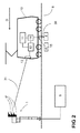
- FIG. 2 shows against the FIG. 1 Representation of the known state of the art - the essential components of the present train control system according to the invention:
- a light signal 1 is connected directly to the signal box 9.
- LED modules 6 a corresponding number of modules 6 'are mounted in the light signal 1 in a chamber 18 of the light signal 1.
- These modules 6 'contain an active RFID tag and an LED module in the manner of the LED module 6 of the known design.
- An RFID read / write unit 13 is mounted on the vehicle 10 for bidirectional communication with the RFID tags 7 on the signal 1.
- this RFID read / write unit 13 will be simply called an RFID receiver 13 or a receiver 13 for short
- the trackside equipment comprises a fixed data balancing group with two fixed data balises 2.
- a mapping unit 12 is connected to the traction vehicle 1 with the RFID receiver 13, the ETCS receiving unit 14 and the vehicle computer 11.
- the fixed data beacon 2 contains a reference Sig Ref to the coming light signal 1.
- the information 31 transmitted by an LED module 6 'to the RFID receiver 13 also contains a further reference Sig Ref' of the relevant signal in a field.
- the two references Sig Ref and Sig Ref ' are first compared with one another in the mapping unit 12. This comparison is particularly required for multi-track sections.
- This problem is the FIG. 3 refer to.
- the RFID receiver 13 receives not only RFID information units 31 from the signals 1 of a parallel track 8, but also signals 1 provided for the inverse direction of travel D '. This differentiation of the direction of travel is made in the ETCS system by arranging two balises. This distinction is also required for the practice of the present invention.
- the information unit 31 has at least the structure shown in Table 1. Table 1: Structure of an information unit 31 RFID tag -> RFID receiver Sig Ref ' Number of chambers Kammer_ID status .. .. CRC
- the signal reference Sigref stored in a balise 2 has the same structure for the relevant signal 1.
- the Kammer_ID is associated with a color (red, yellow, green), but this is not sufficient for the formation of a signal term, see a representation of a pre-signal according to the FIG. 3 :
- the upper two lamps are yellow, the lower ones are green. Between yellow yellow (next main signal shows HALT) and green green (next main signal shows free travel with the maximum permissible line speed), other terms are possible with a combination of yellow and green.
- These combinations are transmitted to the traction vehicle 1 via the RFID information unit 31 in accordance with the optical signaling with color and arrangement, eg number of chambers.
- FIG. 4 is the timing of information transfer to a traction unit 1 exemplified.
- fixed data balises 2 as well as transparent balises 2 are provided on the trackside.
- the correspondingly transmitted information units 30 are identified as 30 fixed and 30 transparent .
- embodiments with only the more cost-effective fixed data balises 2 are conceivable.
- the temporal sequence t and the movement D of a traction vehicle 10 is the continuous, possibly quasi-continuous information transmission with telegrams 31 of a light signal 1 with modules 6 'clearly distinguishable from the pointwise transmission of telegrams 30 from a balise 2 to the traction vehicle 10.
- FIGS. 5A and 5B each show a possible coupling to the RFID tag 7.
- a module 6 'with an LED lamp 17 is mounted in a chamber 18 of the light signal 1, a module 6 'with an LED lamp 17 is mounted.
- the chamber 18 is in itself suitable for compatibility reasons to accommodate a conventional light source.
- a photodiode which detects the lighting state of the LED lamp 17 and reports via a return 21 to the current control 16, the luminous state of the LED lamp 17. From the current control 16, this state can also be transmitted back to the interlocking.
- the current control 16 receives the lighting state from the work station 9 via the lamp circuit 19.
- the RFID tag can now obtain the luminous state from the lamp circuit 19, see the illustration in FIG FIG. 5A , In another embodiment, this luminous state is supplied to the RFID tag 7 from the so-called filament circuit 20.
Landscapes
- Engineering & Computer Science (AREA)
- Mechanical Engineering (AREA)
- Train Traffic Observation, Control, And Security (AREA)
- Electric Propulsion And Braking For Vehicles (AREA)
Abstract
Description
- Die vorliegende Erfindung betrifft ein Zugsicherungssystem und ein Modul für ein Lichtsignal zur Zugsicherung nach dem Oberbegriff des Patentanspruchs 1 bzw. 8.
- Zielsetzung von ETCS ist die Schaffung einer harmonisierten europäischen Zugbeeinflussung. Die Standardisierung bezieht sich insbesondere auf die Informationsübertragung zwischen Fahrweg und Fahrzeug (Luft-Schnittstellen). Die über die Komponenten des ETCS-Systems zu übertragenden Informationen können meist aus den vorhandenen Sicherungsanlagen gewonnen bzw. erzeugt werden.
- ETCS wird in unterschiedlichen Ausrüstungsstufen bzw. Funktionsstufen - sogenannte Levels - unterschieden. Die Definition des Levels hängt davon ab, wie die Strecke ausgerüstet ist und auf welche Art Informationen auf den Zug übertragen werden. Prinzipiell wird die Fahrerlaubnis und die entsprechende Streckeninformation auf den Zug übertragen und dem Lokomotivführer im Führerstand angezeigt.
- In
Figur 1 ist die prinzipielle Anordnung von an Strecken¬punkten angeordneten Balisengruppen des System ETCS/Eurobalise vor einem Lichtsignal 1 dargestellt. Das Lichtsignal 1 ist mit Modulen 6 zur Aussendung von Licht ausgerüstet. Mit dem Bezugszeichen D ist die Fahrtrichtung eines Zuges 10 angegeben. Eine Balisengruppe an den Streckenpunkten beinhaltet wenigstens zwei Balisen 2. Balisen 2 können als stets gleiche Telegramme aussendende Festdatenbalisen oder als steuerbare Transparentbalisen ausgeführt sein. Transparentbalisen übertragen den Inhalt, das ist ein Signalbegriff, eines von einem Adapter LEU entstammenden Telegramms an ein Fahrzeug 10. Die wenigstens paarige Anordnung von Balisen 2 in Balisengruppen ist erforderlich, um bei Überfahrt mittels einer festen Kennung in einem Telegramm die Fahrtrichtung D des überfahrenden Zuges 10 zu erkennen. Das Lichtsignal 1 wie auch die Transparentbalisen 2 erhalten die Informationen von einer LEU 3. - Damit eine kontinuierlichere Informationsübertragung ermöglicht wird, ist das System Euroloop geschaffen worden, damit ein Zug 10 unmittelbar beim Wechsel des Signalbegriffes Halt auf Fahrt beschleunigen kann und nicht bis zum Überfahren der nächsten steuerbaren Transparentbalise warten muss. Dazu ist ein Leckkabel 5 über ein Loop Modem 4 mit der LEU 3 verbunden.
- Auf dem Triebfahrzeug 10 befindet sich eine Antenne 15, die mit einer ETCS-Empfangseinheit 14 gekoppelt ist. Die in der ETCS-Empfangseinheit 14 empfangenen Telegramme 30 werden vom Fahrzeugrechner 11 ausgewertet für die Zugsicherung wie Geschwindigkeitsüberwachung etc.
- Aus der
Figur 1 ist unschwer zu erkennen, dass der Aufwand mit der kontinuierlichen Übertragung ganz erheblich ist. Besonders für Schmalspurbahnen und Bahnen mit eher geringeren Fahrgeschwindigkeiten ist das vorliegende ETCS-System teilweise funktionell, auf jeden Fall aber apparativ überdimensioniert. - Der vorliegenden Erfindung liegt daher die Aufgabe zugrunde, ein Zugsicherungssystem sowie ein Modul für den Einbau in ein Lichtsignal anzugeben, die auf wesentlich einfachere Weise für Bahnen mit kleinerer maximaler Fahrgeschwindigkeit ebenfalls eine kontinuierliche Informationsübertragung zwischen Gleis und Fahrzeug leisten.
- Diese Aufgabe wird durch die in den unabhängigen Patentansprüchen angegebenen Merkmale gelöst. Vorteilhafte Ausgestaltungen der Erfindung sind in weiteren Ansprüchen angegeben.
- So können sich die folgenden Vorteile zusätzlich ergeben:
- i) Es können bestehende ETCS-Komponenten verwendet werden und darauf aufsetzend die vorliegende Erfindung mit einer Signalleucht-sensitiven RFID-Übertragung versehen werden, weitere Anpassungen auf der Infrastrukturseite sind nicht erforderlich.
- ii) Bei für Schmalspurbahnen typischen Geschwindigkeiten erlaubt die vorliegende Erfindung eine kontinuierliche Informationsübertragung, sogenanntes «infill», ohne dass dazu eine aufwendige Technik mit Leckkabel wie z.B. Euroloop dazu bemüht werden muss. Die Funktionalität des Systems ETCS bleibt mit der Erfindung erhalten.
- iii) Die Ankopplung des in einem Modul eines Lichtsignals enthaltenen aktives RFID-Tags kann alternativ oder kumulativ erfolgen durch:
- Optische Ankopplung;
- galvanische Kopplung über den Glühfadenstromkreis
- galvanische Kopplung über den Lampenstromkreis ab Stellwerk.
- Durch die insbesondere optische Ankopplung ist gewährleistet, dass das RFID-Tag stets den korrekten Signalbegriff empfängt.
- iv) Durch die Integration eines aktiven RFID-Tags in ein eine LED-Lichtsignalleuchte enthaltendes Modul beschränkt sich die Aufrüstung/Montage mit dem System der vorliegenden Erfindung auf einen «Austausch der Lampen» bzw. der Module.
- Die Erfindung wird nachfolgend anhand der Zeichnung beispielsweise näher erläutert. Dabei zeigen:
-
Figur 1 Zugsicherungssystem mit den wesentlichen Komponenten gemäss den Standards von ETCS; -
Figur 2 Ausführungsform eines Zugsicherungssystems mit RFID-Tags gemäss der vorliegenden Erfindung; -
Figur 3 Darstellung der Empfangssituation bei Spurwechselbetrieb; -
Figur 4 Darstellung des Meldungsablaufs zwischen Strecke, Fahrzeug und RFID-Tag am Lichtsignal; -
Figur 5 Prinzschema eines LED-Moduls versehen mit einem RFID-Tag. - Die
Figur 2 zeigt gegenüber derFigur 1 - Darstellung des bekannten Standes der Technik - die wesentlichen Komponenten des vorliegenden erfindungsgemässen Zugsicherungssystems: - Ein Lichtsignal 1 ist direkt mit dem Stellwerk 9 verbunden. Anstelle der üblichen LED-Module 6 sind im Lichtsignal 1 in einer Kammer 18 des Lichtsignals 1 eine entsprechende Anzahl Module 6' montiert. Diese Module 6' enthalten ein aktives RFID-Tag und ein LED-Modul in der Art der LED-Modul 6 aus der bekannten Ausführung. Auf dem Fahrzeug 10 ist eine RFID-Schreib-/Leseeinheit 13 angebracht für die bidirektionale Kommunikation mit den RFID-Tags 7 am Signal 1. Im folgenden wird diese RFID-Schreib-/Leseeinheit 13 einfach RFID-Empfänger 13 oder auch kurz Empfänger 13 genannt. Die streckenseitige Ausrüstung umfasst in dieser Ausführungsform eine Fixdatenbalisengruppe mit zwei Fixdatenbalisen 2. Zusätzlich ist auf dem Triebfahrzeug 1 eine Mapping Unit 12 mit dem RFID-Empfänger 13, der ETCS-Empfangseinheit 14 und dem Fahrzeugrechner 11 verbunden.
- Die Fixdatenbalise 2 enthält eine Referenz SigRef zum kommenden Lichtsignal 1. Die von einem LED-Modul 6' an den RFID-Empfänger 13 übermittelte Information 31 enthält in einem Feld ebenfalls eine weitere Referenz SigRef' des betreffenden Signals. Auf dem Triebfahrzeug 1 werden in der Mapping Unit 12 zunächst die beiden Referenzen SigRef und SigRef' miteinander verglichen. Dieser Vergleich ist insbesondere erforderlich bei Mehrspurstreckenabschnitten. Diese Problematik ist der
Figur 3 zu entnehmen. In der Umgebung eines Signals 1 empfängt der RFID-Empfänger 13 nicht nur RFID-Informationseinheiten 31 von den Signalen 1 eines parallelen Gleises 8, sondern auch von Signalen 1, die für die inverse Fahrrichtung D' vorgesehen sind. Diese Unterscheidung der Fahrtrichtung wird beim ETCS-System vorgenommen durch Anordnung von zwei Balisen. Diese Unterscheidung ist für die Ausführung der vorliegenden Erfindung ebenfalls erforderlich. Die Informationseinheit 31 hat mindestens die in Tabelle 1 dargestellte Struktur.Tabelle 1: Struktur einer Informationseinheit 31 RFID-Tag -> RFID-Empfänger SigRef' Anzahl Kammern Kammer_ID Status .. .. CRC - Pro LED-Modul 6' wird eine solche Informationseinheit 31 übermittelt. Die Mapping Unit 12 bildet aus der Mehrzahl der vorgenannten verschiedenen Informationseinheiten 31 einen Signalbegriff. Die in Tabelle 1 gezeigte Struktur ist rein beispielhaft. Die Referenz SigRef' kann in einer längeren alphanumerischen -Darstellung gebildet sein und gemäss einem übergeordneten Schema beinhalten:
- Strecken-Referenz;
- Richtungsreferenz;
- Signalnummer
- Signaltyp;
- .. ..
- Die in einer Balise 2 gespeicherte Signalreferenz SigRef hat für das betreffende Signal 1 den gleichen Aufbau.
- Die Kammer_ID ist mit einer Farbe (Rot, gelb, grün) verknüpft, dies reicht jedoch nicht aus für die Bildung eines Signalbegriffs, siehe dazu eine Darstellung eines Vorsignals gemäss der
Figur 3 : Die oberen zwei Lampen sind gelb, die unteren grün. Zwischen den Anzeigen «Gelb Gelb» (nächstes Hauptsignal zeigt HALT) und «Grün Grün» (nächstes Hauptsignal zeigt freie Fahrt mit der max. zulässigen Streckengeschwindigkeit) sind weitere Begriffe möglich mit einer Kombination von gelb und grün. Diese Kombinationen werden entsprechend der optischen Signalisierung mit Farbe und Anordnung, z.B. Anzahl Kammern, über die RFID-Informationseinheit 31 auf des Triebfahrzeug 1 übermittelt. - In der
Figur 4 ist der zeitliche Ablauf der Informationsübertragung auf ein Triebfahrzeug 1 beispielhaft dargestellt. In diesem Beispiel sind streckenseitig sowohl Fixdatenbalisen 2 wie auch Transparentbalisen 2 vorgesehen. Die entsprechend übermittelten Informationseinheiten 30 sind mit 30fix und 30transparent gekennzeichnet. Es sind vor allem für Bahnen mit geringeren Anforderungen hinsichtlich der Sicherheit auch Ausführungen nur mit den kostengünstigeren Fixdatenbalisen 2 denkbar. In der zeitlichen Abfolge t und der Bewegung D eines Triebfahrzeuges 10 ist die kontinuierliche, allenfalls quasikontinuierliche Informationsübertragung mit Telegrammen 31 von einem Lichtsignal 1 mit Modulen 6' deutlich zu unterscheiden von der punkteweisen Übertragung von Telegrammen 30 von einer Balise 2 zum Triebfahrzeug 10. Ausgehend vom von einer Balise 2 entstammenden Telegramm 30 erfolgt in der Mapping Unit 12 die Zuordnung von empfangenen Informationseinheiten 31 zu einem Signalbegriff eines bestimmten Lichtsignals 1. Besonders in einer Mehrspurumgebung sind daher von der Mapping Unit 12 eine erhebliche Anzahl von empfangenen Informationseinheiten 31 zu verwerfen, da die Referenzen SigRef' und SigRef' nicht übereinstimmen. - Die
Figuren 5A und 5B zeigen je eine mögliche Kopplung zum RFID-Tag 7. In einer Kammer 18 des Lichtsignals 1 ist ein Modul 6' mit einer LED-Lampe 17 montiert. Die Kammer 18 ist an und für sich aus Kompatibilitätsgründen auch geeignet, eine konventionelle Lichtquelle aufzunehmen. In beiden Darstellungen gemäss denFiguren 5A und 5B ist in der LED-Lampe 17 eine Photodiode enthalten, die den Leuchtzustand der LED-Lampe 17 erfasst und über eine Rückführung 21 an die Stromregelung 16 den Leuchtzustand der LED-Lampe 17 meldet. Von der Stromregelung 16 kann dieser Zustand auch rückwärts an das Stellwerk übermittelt werden. Die Stromregelung 16 erhält den Leuchtzustand ab Stellewerk 9 über den Lampenstromkreis 19. Gemäss einer Ausführung der vorliegenden Erfindung kann das RFID-Tag den Leuchtzustand nun vom Lampenstromkreis 19 beziehen, siehe dazu die Darstellung inFigur 5A . In einer anderen Ausführung wird dieser Leuchtzustand ab dem sogenannten Glühfadenstromkreis 20 dem RFID-Tag 7 zugeführt. - In einer weiteren Ausgestaltung ist es auch möglich, das RFID-Tag 7 optisch an die LED-Lampe anzukoppeln, beispielsweise über die bereits vorhandene Photodiode oder eine zusätzliche auf dem RFID-Tag 7 befindliche Diode. Diese Ausführungen haben alle den grossen Vorteil, dass durch den alleinigen Tausch eines LED-Moduls 6 der herkömmlichen Bauart durch ein LED-Modul 6' gemäss einer Ausführungsform der vorliegenden Erfindung auszutauschen.
- Für den Austausch selber sind die RFID-Tags 7 mit den spezifischen Daten, vgl. vorstehende Tabelle 1, zu versehen. Dies kann auch vor Ort vorgenommen werden durch eine gesicherte bidirektionale Kommunikation mit dem RFID-Tag 7.
-
- 1
- Lichtsignal; Eisenbahnlichtsignals; Hauptsignal, Vorsignal
- 2
- Balise, Transparentdatenbalise, Fixdatenbalise; Transparentbalise
- 3
- LEU, Lineside Electronic Unit
- 4
- Loop Modem
- 5
- Leckkabel, Euroloop
- 6
- Modul zur Aussendung von Licht, LED-Modul
- 6'
- Modul enthaltend RFID-Tag und LED-Lampe/Leuchtmittel zur Aussendung von Licht
- 7
- RFID-Tag, aktives RFID-Tag
- 8
- Gleis
- 9
- Stellwerk
- 10
- Triebfahrzeug, Eisenbahnfahrzeug; Zug
- 11
- Fahrzeugrechner, Electronic Vehicle Controller EVC
- 12
- Selektionsgerät; Mapping Unit
- 13
- Empfänger, RFID-Schreib-/Leseeinheit
- 14
- Empfangseinheit, Decoder, ETCS-Empfangseinheit
- 15
- Antenne
- 16
- Stromregelung
- 17
- LED-Lampe; Leuchtmittel
- 18
- Kammer
- 19
- Lampenstromkreis ab Stellwerk
- 20
- Glühfadenstromkreis ab Stromregelung
- 21
- Rückführung zur Kontrolle des LED-Zustandes
- 30
- Übertragene Information zwischen Balise und Fahrzeug bzw. Decoder; Telegramm
- 31
- Übertragene Information zwischen RFID-Tag und RFID-Schreib-/Leseeinheit; Telegramm
- D
- Fahrtrichtung
- SigRef
- In einer Balise 2 gespeicherte Signalreferenz
- SigRef'
- In einem RFID-Tag 7 gespeicherte Signalreferenz
-
- CRC
- Cyclic Redundancy Check
- ERTMS
- European Rail Traffic Management System in Kurzform: ERTMS = ETCS + GSMR
- ETCS
- European Train Control System
- GSMR
- Global System for Mobile Communications - Railways
- LEU
- Lineside Electronic Unit
- SPS
- speicherprogrammierte Schaltung
-
- [1] http://www.ertms.com/
- LEU Lineside Electronic Unit
- http://www.ertms.com/leve101.html
Claims (13)
- Zugsicherungssystem mit einem vor einem Lichtsignal (1) im Gleis (8) angeordneten angeordneten Balise (2) zur Übertragung von Information (30) zwischen der Balise (2) und einem darüber befindlichen Eisenbahnfahrzeug (10), wobei- die zu übertragende Information (30) eine das Lichtsignal (1) repräsentierende Referenz (SigRef) enthält;- das Lichtsignal (1) mehrere je ein Leuchtmittel (17) enthaltende Module (6') zur Aussendung von Licht aufweist;- das Eisenbahnfahrzeug (10) einen Decoder (14) zum Empfang der von der Balise(2) übertragenen Information (30) aufweist und der Decoder (14) mit einem Fahrzeugrechner (11) verbunden ist, der die übertragene Information (30) verarbeitet;dadurch gekennzeichnet, dass
jedes Modul (6') ein aktives RFID-Tag (7) enthält und mit dem Leuchtmittel (17) gekoppelt ist, wobei im RFID-Tag (7) ein Leuchtzustand des Leuchtmittels (17) und eine Referenz (SigRef') des zugehörigen Lichtsignals (1) codiert gespeichert ist, so dass von einem auf dem Eisenbahnfahrzeug (10) angeordneten RFID-Empfänger (13) der Leuchtzustand eines Leuchtmittels (17) und die Referenz (SigRef') des zugehörigen Lichtsignals (1) empfangbar (31) ist und der RFID-Empfänger (13) mit dem Fahrzeugrechner (11) verbunden ist zur Verarbeitung der empfangenen Informationen (30, 31) zu einem Signalbegriff. - Zugsicherungssystem nach Anspruch 1,
dadurch gekennzeichnet, dass
das Leuchtmittel eine LED-Lampe (17) ist. - Zugsicherungssystem nach Anspruch 1 oder 2,
dadurch gekennzeichnet, dass
die Kopplung des RFID-Tags (7) optisch mit dem Leuchtmittel (17) erfolgt. - Zugsicherungssystem nach Anspruch 1 oder 2,
dadurch gekennzeichnet, dass
die Kopplung des RFID-Tags (7) galvanisch innerhalb des Moduls (6') erfolgt. - Zugsicherungssystem nach einem der Ansprüche 1 bis 4,
dadurch gekennzeichnet, dass
das Modul (6') in eine Kammer (18) des Lichtsignals (1) einsetzbar ist. - Zugsicherungssystem nach einem der Ansprüche 1 bis 5,
dadurch gekennzeichnet, dass
die ein Lichtsignal (1) repräsentierende Referenz (SigRef', SigRef') gebildet wird aus je einer- Strecken-Referenz;- Richtungsreferenz;- Signalnummer und einem- Signaltyp. - Zugsicherungssystem nach einem der Ansprüche 1 bis 6,
dadurch gekennzeichnet, dass
die ein Lichtsignal (1) repräsentierende Referenz (SigRef', SigRef') vor Ort im RFID-Tag (7) des Moduls (6') festschreibbar ist. - Modul (6') zum Einbau in eine Kammer (1) eines Eisenbahnlichtsignals (1) enthaltend ein Leuchtmittel (17) zur Aussendung von Licht;
dadurch gekennzeichnet, dass
im Modul (6') ein aktives RFID-Tag (7) angeordnet ist und mit dem Leuchtmittel (17) gekoppelt ist, wobei im RFID-Tag (7) ein Leuchtzustand des Leuchtmittels (17) und eine Referenz (SigRef') des zugehörigen Lichtsignals (1) codiert gespeichert ist, so dass von einem auf einem Eisenbahnfahrzeug (10) angeordneten RFID-Empfänger (13) der Leuchtzustand eines Leuchtmittels (17) und die Referenz (SigRef') des zugehörigen Lichtsignals (1) empfangbar (31) ist. - Modul (6') nach Anspruch 8,
dadurch gekennzeichnet, dass
das Leuchtmittel (17) eine LED-Lampe (17) ist. - Modul (6') nach Anspruch 8 oder 9,
dadurch gekennzeichnet, dass
die Kopplung des RFID-Tags (7) optisch mit dem Leuchtmittel (17) erfolgt. - Modul (6') nach Anspruch 8 oder 9,
dadurch gekennzeichnet, dass
die Kopplung des RFID-Tags (7) galvanisch innerhalb des Moduls (6') erfolgt. - Modul (6') nach einem der Ansprüche 8 bis 11,
dadurch gekennzeichnet, dass
die ein Lichtsignal (1) repräsentierende Referenz (SigRef', SigRef') gebildet wird aus je einer- Strecken-Referenz;- Richtungsreferenz;- Signalnummer und einem- Signaltyp. - Modul (6') nach einem der Ansprüche 8 bis 12,
dadurch gekennzeichnet, dass
die ein Lichtsignal (1) repräsentierende Referenz (SigRef', SigRef') vor Ort im RFID-Tag (7) des Moduls (6') festschreibbar ist.
Priority Applications (2)
| Application Number | Priority Date | Filing Date | Title |
|---|---|---|---|
| EP08170645A EP2193972B1 (de) | 2008-12-04 | 2008-12-04 | Zugsicherungssystem |
| AT08170645T ATE518717T1 (de) | 2008-12-04 | 2008-12-04 | Zugsicherungssystem |
Applications Claiming Priority (1)
| Application Number | Priority Date | Filing Date | Title |
|---|---|---|---|
| EP08170645A EP2193972B1 (de) | 2008-12-04 | 2008-12-04 | Zugsicherungssystem |
Publications (2)
| Publication Number | Publication Date |
|---|---|
| EP2193972A1 true EP2193972A1 (de) | 2010-06-09 |
| EP2193972B1 EP2193972B1 (de) | 2011-08-03 |
Family
ID=40527961
Family Applications (1)
| Application Number | Title | Priority Date | Filing Date |
|---|---|---|---|
| EP08170645A Not-in-force EP2193972B1 (de) | 2008-12-04 | 2008-12-04 | Zugsicherungssystem |
Country Status (2)
| Country | Link |
|---|---|
| EP (1) | EP2193972B1 (de) |
| AT (1) | ATE518717T1 (de) |
Cited By (3)
| Publication number | Priority date | Publication date | Assignee | Title |
|---|---|---|---|---|
| US20150291188A1 (en) * | 2012-09-28 | 2015-10-15 | Siemens Aktiengesellschaft | Controller of a rail vehicle |
| WO2016150708A1 (de) * | 2015-03-23 | 2016-09-29 | Siemens Aktiengesellschaft | Verfahren und vorrichtung zur fahrzeugseitigen positionsdatenerfassung bei einem schienenfahrzeug mittels laufzeitmessung |
| WO2018046217A1 (de) * | 2016-09-09 | 2018-03-15 | Siemens Aktiengesellschaft | Verfahren zum übermitteln einer information von einer streckenseitigen einrichtung zu einem fahrzeug sowie einrichtungen zum durchführen eines solchen verfahrens |
Families Citing this family (1)
| Publication number | Priority date | Publication date | Assignee | Title |
|---|---|---|---|---|
| EP2684760B1 (de) | 2012-07-13 | 2021-04-21 | Siemens Mobility AG | Zugsteuersystem auf Basis eines ETCS-Vollüberwachungsmodus |
Citations (3)
| Publication number | Priority date | Publication date | Assignee | Title |
|---|---|---|---|---|
| DE4038267A1 (de) * | 1989-12-04 | 1991-06-06 | Siemens Ag | Einrichtung zur punktweisen daten- und energieuebertragung |
| GB2374188A (en) * | 2001-07-11 | 2002-10-09 | John Alexander Scott | Train safety signal display |
| GB2399206A (en) * | 2003-03-05 | 2004-09-08 | Qinetiq Ltd | Signalling system with visible and non visible signals |
-
2008
- 2008-12-04 AT AT08170645T patent/ATE518717T1/de active
- 2008-12-04 EP EP08170645A patent/EP2193972B1/de not_active Not-in-force
Patent Citations (3)
| Publication number | Priority date | Publication date | Assignee | Title |
|---|---|---|---|---|
| DE4038267A1 (de) * | 1989-12-04 | 1991-06-06 | Siemens Ag | Einrichtung zur punktweisen daten- und energieuebertragung |
| GB2374188A (en) * | 2001-07-11 | 2002-10-09 | John Alexander Scott | Train safety signal display |
| GB2399206A (en) * | 2003-03-05 | 2004-09-08 | Qinetiq Ltd | Signalling system with visible and non visible signals |
Non-Patent Citations (1)
| Title |
|---|
| GREITER G ET AL: "MIGRATION ZUB 121 / EURO-BALISE BEI DEN SBB", SIGNAL + DRAHT, TELZLAFF VERLAG GMBH. DARMSTADT, DE, vol. 89, no. 10, 1 October 1997 (1997-10-01), pages 22 - 24, XP000779776, ISSN: 0037-4997 * |
Cited By (3)
| Publication number | Priority date | Publication date | Assignee | Title |
|---|---|---|---|---|
| US20150291188A1 (en) * | 2012-09-28 | 2015-10-15 | Siemens Aktiengesellschaft | Controller of a rail vehicle |
| WO2016150708A1 (de) * | 2015-03-23 | 2016-09-29 | Siemens Aktiengesellschaft | Verfahren und vorrichtung zur fahrzeugseitigen positionsdatenerfassung bei einem schienenfahrzeug mittels laufzeitmessung |
| WO2018046217A1 (de) * | 2016-09-09 | 2018-03-15 | Siemens Aktiengesellschaft | Verfahren zum übermitteln einer information von einer streckenseitigen einrichtung zu einem fahrzeug sowie einrichtungen zum durchführen eines solchen verfahrens |
Also Published As
| Publication number | Publication date |
|---|---|
| ATE518717T1 (de) | 2011-08-15 |
| EP2193972B1 (de) | 2011-08-03 |
Similar Documents
| Publication | Publication Date | Title |
|---|---|---|
| EP3612430B1 (de) | Verfahren zum betreiben eines spurgebundenen verkehrssystems und vorrichtung | |
| EP2170673B1 (de) | Verfahren und anordnung zum betreiben einer eisenbahnstrecke | |
| EP2421737A1 (de) | Verfahren und vorrichtung zur steuerung von eisenbahnsicherungssystemen | |
| WO2019243341A1 (de) | Flexibles zugsicherungssystem | |
| EP2473391B1 (de) | Verfahren zur übertragung von daten von einer streckenseitigen einrichtung an ein fahrzeug sowie fahrzeugseitige und streckenseitige einrichtung | |
| EP1999001B1 (de) | Einrichtung zur anschaltung und überwachung einer lichtsignalanlage im eisenbahnverkehr | |
| DE102017209928A1 (de) | Verfahren zum Betreiben eines spurgebundenen Verkehrssystems | |
| EP2193972B1 (de) | Zugsicherungssystem | |
| DE102016211482A1 (de) | Verfahren sowie Anordnung zum Sichern eines Bahnübergangs | |
| EP2230148A1 (de) | Verfahren und System zur Identifizierung von Gleissicherungseinrichtungen | |
| WO2010145948A1 (de) | Verfahren zum übertragen von daten von einem programmiergerät an eine balise eines zugbeeinflussungssystems, programmiergerät sowie balise | |
| WO2006056284A1 (de) | Verfahren und system zur überprüfung einer datenübertragungseinheit zur steuerung eines fahrenden objektes | |
| EP2178733B1 (de) | Verfahren zur erzielung einer aufwandsarmen einbindung von dezentralen feldkomponenten im schienengebundenen verkehr in ein steuerungssystem | |
| EP3681779B1 (de) | Verfahren, streckenseitige übertragungseinrichtung und subsystem für ein zugbeeinflussungssystem | |
| EP4116170A1 (de) | Verfahren zum betreiben eines zugbeeinflussungssystems | |
| WO2014048736A2 (de) | Steuerung eines schienenfahrzeugs | |
| EP2121410B1 (de) | Verfahren und system zum datenaustausch zwischen einer zentralen einheit und einer zugbeeinflussungskomponente | |
| EP2708439B1 (de) | Verfahren und System zum Extrahieren eines Signalbegriffs aus einem Magnetkreis | |
| DE102014002297B4 (de) | Verfahren zum vorbildgerechten Betreiben von Modellfahrzeugen einer Modellbahnanlage | |
| EP4101726B1 (de) | System zum testen der korrekten abfolge und übertragung von für eine onboard-unit eines fahrzeugs vorgesehenen balisen- und/oder looptelegrammen | |
| EP2489570B1 (de) | Verfahren und System zum Datenaustausch zwischen einer zentralen Einheit und einer Zugbeeinflussungskomponente zu Testzwecken | |
| EP3400161A1 (de) | Bahntechnische anlage und verfahren zum betreiben einer bahntechnischen anlage | |
| DE102004030521A1 (de) | Verfahren zur Zugbeeinflussung | |
| DE102011054422A1 (de) | Zugsicherungssystem | |
| EP2399802A2 (de) | Fahrzeuggerät für ein System zur punktförmigen induktiven Zugbeeinflussung |
Legal Events
| Date | Code | Title | Description |
|---|---|---|---|
| PUAI | Public reference made under article 153(3) epc to a published international application that has entered the european phase |
Free format text: ORIGINAL CODE: 0009012 |
|
| AK | Designated contracting states |
Kind code of ref document: A1 Designated state(s): AT BE BG CH CY CZ DE DK EE ES FI FR GB GR HR HU IE IS IT LI LT LU LV MC MT NL NO PL PT RO SE SI SK TR |
|
| AX | Request for extension of the european patent |
Extension state: AL BA MK RS |
|
| 17P | Request for examination filed |
Effective date: 20100906 |
|
| 17Q | First examination report despatched |
Effective date: 20100927 |
|
| GRAP | Despatch of communication of intention to grant a patent |
Free format text: ORIGINAL CODE: EPIDOSNIGR1 |
|
| AKX | Designation fees paid |
Designated state(s): AT BE BG CH CY CZ DE DK EE ES FI FR GB GR HR HU IE IS IT LI LT LU LV MC MT NL NO PL PT RO SE SI SK TR |
|
| RIN1 | Information on inventor provided before grant (corrected) |
Inventor name: SCHMID, ROLF |
|
| GRAS | Grant fee paid |
Free format text: ORIGINAL CODE: EPIDOSNIGR3 |
|
| GRAA | (expected) grant |
Free format text: ORIGINAL CODE: 0009210 |
|
| AK | Designated contracting states |
Kind code of ref document: B1 Designated state(s): AT BE BG CH CY CZ DE DK EE ES FI FR GB GR HR HU IE IS IT LI LT LU LV MC MT NL NO PL PT RO SE SI SK TR |
|
| REG | Reference to a national code |
Ref country code: GB Ref legal event code: FG4D Free format text: NOT ENGLISH |
|
| REG | Reference to a national code |
Ref country code: CH Ref legal event code: EP Ref country code: CH Ref legal event code: NV Representative=s name: SIEMENS SCHWEIZ AG |
|
| REG | Reference to a national code |
Ref country code: IE Ref legal event code: FG4D Free format text: LANGUAGE OF EP DOCUMENT: GERMAN |
|
| REG | Reference to a national code |
Ref country code: DE Ref legal event code: R096 Ref document number: 502008004381 Country of ref document: DE Effective date: 20111006 |
|
| REG | Reference to a national code |
Ref country code: NL Ref legal event code: VDEP Effective date: 20110803 |
|
| LTIE | Lt: invalidation of european patent or patent extension |
Effective date: 20110803 |
|
| PG25 | Lapsed in a contracting state [announced via postgrant information from national office to epo] |
Ref country code: NO Free format text: LAPSE BECAUSE OF FAILURE TO SUBMIT A TRANSLATION OF THE DESCRIPTION OR TO PAY THE FEE WITHIN THE PRESCRIBED TIME-LIMIT Effective date: 20111103 Ref country code: FI Free format text: LAPSE BECAUSE OF FAILURE TO SUBMIT A TRANSLATION OF THE DESCRIPTION OR TO PAY THE FEE WITHIN THE PRESCRIBED TIME-LIMIT Effective date: 20110803 Ref country code: HR Free format text: LAPSE BECAUSE OF FAILURE TO SUBMIT A TRANSLATION OF THE DESCRIPTION OR TO PAY THE FEE WITHIN THE PRESCRIBED TIME-LIMIT Effective date: 20110803 Ref country code: NL Free format text: LAPSE BECAUSE OF FAILURE TO SUBMIT A TRANSLATION OF THE DESCRIPTION OR TO PAY THE FEE WITHIN THE PRESCRIBED TIME-LIMIT Effective date: 20110803 Ref country code: LT Free format text: LAPSE BECAUSE OF FAILURE TO SUBMIT A TRANSLATION OF THE DESCRIPTION OR TO PAY THE FEE WITHIN THE PRESCRIBED TIME-LIMIT Effective date: 20110803 Ref country code: PT Free format text: LAPSE BECAUSE OF FAILURE TO SUBMIT A TRANSLATION OF THE DESCRIPTION OR TO PAY THE FEE WITHIN THE PRESCRIBED TIME-LIMIT Effective date: 20111205 Ref country code: SE Free format text: LAPSE BECAUSE OF FAILURE TO SUBMIT A TRANSLATION OF THE DESCRIPTION OR TO PAY THE FEE WITHIN THE PRESCRIBED TIME-LIMIT Effective date: 20110803 Ref country code: IS Free format text: LAPSE BECAUSE OF FAILURE TO SUBMIT A TRANSLATION OF THE DESCRIPTION OR TO PAY THE FEE WITHIN THE PRESCRIBED TIME-LIMIT Effective date: 20111203 |
|
| PG25 | Lapsed in a contracting state [announced via postgrant information from national office to epo] |
Ref country code: LV Free format text: LAPSE BECAUSE OF FAILURE TO SUBMIT A TRANSLATION OF THE DESCRIPTION OR TO PAY THE FEE WITHIN THE PRESCRIBED TIME-LIMIT Effective date: 20110803 Ref country code: SI Free format text: LAPSE BECAUSE OF FAILURE TO SUBMIT A TRANSLATION OF THE DESCRIPTION OR TO PAY THE FEE WITHIN THE PRESCRIBED TIME-LIMIT Effective date: 20110803 Ref country code: PL Free format text: LAPSE BECAUSE OF FAILURE TO SUBMIT A TRANSLATION OF THE DESCRIPTION OR TO PAY THE FEE WITHIN THE PRESCRIBED TIME-LIMIT Effective date: 20110803 Ref country code: GR Free format text: LAPSE BECAUSE OF FAILURE TO SUBMIT A TRANSLATION OF THE DESCRIPTION OR TO PAY THE FEE WITHIN THE PRESCRIBED TIME-LIMIT Effective date: 20111104 Ref country code: CY Free format text: LAPSE BECAUSE OF FAILURE TO SUBMIT A TRANSLATION OF THE DESCRIPTION OR TO PAY THE FEE WITHIN THE PRESCRIBED TIME-LIMIT Effective date: 20110803 |
|
| REG | Reference to a national code |
Ref country code: IE Ref legal event code: FD4D |
|
| PG25 | Lapsed in a contracting state [announced via postgrant information from national office to epo] |
Ref country code: CZ Free format text: LAPSE BECAUSE OF FAILURE TO SUBMIT A TRANSLATION OF THE DESCRIPTION OR TO PAY THE FEE WITHIN THE PRESCRIBED TIME-LIMIT Effective date: 20110803 Ref country code: SK Free format text: LAPSE BECAUSE OF FAILURE TO SUBMIT A TRANSLATION OF THE DESCRIPTION OR TO PAY THE FEE WITHIN THE PRESCRIBED TIME-LIMIT Effective date: 20110803 Ref country code: IE Free format text: LAPSE BECAUSE OF FAILURE TO SUBMIT A TRANSLATION OF THE DESCRIPTION OR TO PAY THE FEE WITHIN THE PRESCRIBED TIME-LIMIT Effective date: 20110803 |
|
| PG25 | Lapsed in a contracting state [announced via postgrant information from national office to epo] |
Ref country code: EE Free format text: LAPSE BECAUSE OF FAILURE TO SUBMIT A TRANSLATION OF THE DESCRIPTION OR TO PAY THE FEE WITHIN THE PRESCRIBED TIME-LIMIT Effective date: 20110803 Ref country code: RO Free format text: LAPSE BECAUSE OF FAILURE TO SUBMIT A TRANSLATION OF THE DESCRIPTION OR TO PAY THE FEE WITHIN THE PRESCRIBED TIME-LIMIT Effective date: 20110803 Ref country code: IT Free format text: LAPSE BECAUSE OF FAILURE TO SUBMIT A TRANSLATION OF THE DESCRIPTION OR TO PAY THE FEE WITHIN THE PRESCRIBED TIME-LIMIT Effective date: 20110803 |
|
| PLBE | No opposition filed within time limit |
Free format text: ORIGINAL CODE: 0009261 |
|
| STAA | Information on the status of an ep patent application or granted ep patent |
Free format text: STATUS: NO OPPOSITION FILED WITHIN TIME LIMIT |
|
| PG25 | Lapsed in a contracting state [announced via postgrant information from national office to epo] |
Ref country code: DK Free format text: LAPSE BECAUSE OF FAILURE TO SUBMIT A TRANSLATION OF THE DESCRIPTION OR TO PAY THE FEE WITHIN THE PRESCRIBED TIME-LIMIT Effective date: 20110803 |
|
| BERE | Be: lapsed |
Owner name: SIEMENS SCHWEIZ A.G. Effective date: 20111231 |
|
| 26N | No opposition filed |
Effective date: 20120504 |
|
| PG25 | Lapsed in a contracting state [announced via postgrant information from national office to epo] |
Ref country code: MC Free format text: LAPSE BECAUSE OF NON-PAYMENT OF DUE FEES Effective date: 20111231 |
|
| REG | Reference to a national code |
Ref country code: DE Ref legal event code: R097 Ref document number: 502008004381 Country of ref document: DE Effective date: 20120504 |
|
| REG | Reference to a national code |
Ref country code: FR Ref legal event code: ST Effective date: 20120831 |
|
| PG25 | Lapsed in a contracting state [announced via postgrant information from national office to epo] |
Ref country code: BE Free format text: LAPSE BECAUSE OF NON-PAYMENT OF DUE FEES Effective date: 20111231 |
|
| PG25 | Lapsed in a contracting state [announced via postgrant information from national office to epo] |
Ref country code: MT Free format text: LAPSE BECAUSE OF FAILURE TO SUBMIT A TRANSLATION OF THE DESCRIPTION OR TO PAY THE FEE WITHIN THE PRESCRIBED TIME-LIMIT Effective date: 20110803 |
|
| PGFP | Annual fee paid to national office [announced via postgrant information from national office to epo] |
Ref country code: GB Payment date: 20121212 Year of fee payment: 5 |
|
| PG25 | Lapsed in a contracting state [announced via postgrant information from national office to epo] |
Ref country code: FR Free format text: LAPSE BECAUSE OF NON-PAYMENT OF DUE FEES Effective date: 20120102 Ref country code: ES Free format text: LAPSE BECAUSE OF FAILURE TO SUBMIT A TRANSLATION OF THE DESCRIPTION OR TO PAY THE FEE WITHIN THE PRESCRIBED TIME-LIMIT Effective date: 20111114 |
|
| PGFP | Annual fee paid to national office [announced via postgrant information from national office to epo] |
Ref country code: DE Payment date: 20130218 Year of fee payment: 5 Ref country code: CH Payment date: 20130312 Year of fee payment: 5 |
|
| PG25 | Lapsed in a contracting state [announced via postgrant information from national office to epo] |
Ref country code: LU Free format text: LAPSE BECAUSE OF NON-PAYMENT OF DUE FEES Effective date: 20111204 |
|
| PG25 | Lapsed in a contracting state [announced via postgrant information from national office to epo] |
Ref country code: BG Free format text: LAPSE BECAUSE OF FAILURE TO SUBMIT A TRANSLATION OF THE DESCRIPTION OR TO PAY THE FEE WITHIN THE PRESCRIBED TIME-LIMIT Effective date: 20111103 |
|
| PG25 | Lapsed in a contracting state [announced via postgrant information from national office to epo] |
Ref country code: TR Free format text: LAPSE BECAUSE OF FAILURE TO SUBMIT A TRANSLATION OF THE DESCRIPTION OR TO PAY THE FEE WITHIN THE PRESCRIBED TIME-LIMIT Effective date: 20110803 |
|
| PG25 | Lapsed in a contracting state [announced via postgrant information from national office to epo] |
Ref country code: HU Free format text: LAPSE BECAUSE OF FAILURE TO SUBMIT A TRANSLATION OF THE DESCRIPTION OR TO PAY THE FEE WITHIN THE PRESCRIBED TIME-LIMIT Effective date: 20110803 |
|
| REG | Reference to a national code |
Ref country code: DE Ref legal event code: R119 Ref document number: 502008004381 Country of ref document: DE |
|
| REG | Reference to a national code |
Ref country code: CH Ref legal event code: PL |
|
| GBPC | Gb: european patent ceased through non-payment of renewal fee |
Effective date: 20131204 |
|
| REG | Reference to a national code |
Ref country code: DE Ref legal event code: R119 Ref document number: 502008004381 Country of ref document: DE Effective date: 20140701 |
|
| PG25 | Lapsed in a contracting state [announced via postgrant information from national office to epo] |
Ref country code: LI Free format text: LAPSE BECAUSE OF NON-PAYMENT OF DUE FEES Effective date: 20131231 Ref country code: CH Free format text: LAPSE BECAUSE OF NON-PAYMENT OF DUE FEES Effective date: 20131231 Ref country code: DE Free format text: LAPSE BECAUSE OF NON-PAYMENT OF DUE FEES Effective date: 20140701 |
|
| PG25 | Lapsed in a contracting state [announced via postgrant information from national office to epo] |
Ref country code: GB Free format text: LAPSE BECAUSE OF NON-PAYMENT OF DUE FEES Effective date: 20131204 |
|
| REG | Reference to a national code |
Ref country code: AT Ref legal event code: MM01 Ref document number: 518717 Country of ref document: AT Kind code of ref document: T Effective date: 20131204 |
|
| PG25 | Lapsed in a contracting state [announced via postgrant information from national office to epo] |
Ref country code: AT Free format text: LAPSE BECAUSE OF NON-PAYMENT OF DUE FEES Effective date: 20131204 |