EP2192544B1 - Image processing apparatus and image processing method for correcting face image - Google Patents
Image processing apparatus and image processing method for correcting face image Download PDFInfo
- Publication number
- EP2192544B1 EP2192544B1 EP09177131A EP09177131A EP2192544B1 EP 2192544 B1 EP2192544 B1 EP 2192544B1 EP 09177131 A EP09177131 A EP 09177131A EP 09177131 A EP09177131 A EP 09177131A EP 2192544 B1 EP2192544 B1 EP 2192544B1
- Authority
- EP
- European Patent Office
- Prior art keywords
- image
- face
- distance
- outline
- eye
- Prior art date
- Legal status (The legal status is an assumption and is not a legal conclusion. Google has not performed a legal analysis and makes no representation as to the accuracy of the status listed.)
- Active
Links
- 238000012545 processing Methods 0.000 title claims description 58
- 238000003672 processing method Methods 0.000 title claims description 5
- 238000012937 correction Methods 0.000 claims description 18
- 238000001514 detection method Methods 0.000 claims description 16
- 210000004709 eyebrow Anatomy 0.000 claims description 9
- 238000004364 calculation method Methods 0.000 claims description 7
- 238000003702 image correction Methods 0.000 description 32
- 230000006870 function Effects 0.000 description 19
- 238000003384 imaging method Methods 0.000 description 7
- 230000004044 response Effects 0.000 description 7
- 238000000034 method Methods 0.000 description 3
- 230000003287 optical effect Effects 0.000 description 3
- 238000010586 diagram Methods 0.000 description 2
- 238000006243 chemical reaction Methods 0.000 description 1
- 230000000295 complement effect Effects 0.000 description 1
- 230000006835 compression Effects 0.000 description 1
- 238000007906 compression Methods 0.000 description 1
- 238000004590 computer program Methods 0.000 description 1
- 230000000994 depressogenic effect Effects 0.000 description 1
- 238000013461 design Methods 0.000 description 1
- 229910044991 metal oxide Inorganic materials 0.000 description 1
- 150000004706 metal oxides Chemical class 0.000 description 1
- 238000012986 modification Methods 0.000 description 1
- 230000004048 modification Effects 0.000 description 1
- 230000008569 process Effects 0.000 description 1
- 210000001747 pupil Anatomy 0.000 description 1
- 239000004065 semiconductor Substances 0.000 description 1
- 238000010408 sweeping Methods 0.000 description 1
- 230000009466 transformation Effects 0.000 description 1
Images


Classifications
-
- G—PHYSICS
- G06—COMPUTING; CALCULATING OR COUNTING
- G06T—IMAGE DATA PROCESSING OR GENERATION, IN GENERAL
- G06T5/00—Image enhancement or restoration
- G06T5/80—Geometric correction
-
- G—PHYSICS
- G06—COMPUTING; CALCULATING OR COUNTING
- G06T—IMAGE DATA PROCESSING OR GENERATION, IN GENERAL
- G06T7/00—Image analysis
-
- G—PHYSICS
- G06—COMPUTING; CALCULATING OR COUNTING
- G06T—IMAGE DATA PROCESSING OR GENERATION, IN GENERAL
- G06T3/00—Geometric image transformations in the plane of the image
- G06T3/18—Image warping, e.g. rearranging pixels individually
-
- G—PHYSICS
- G06—COMPUTING; CALCULATING OR COUNTING
- G06T—IMAGE DATA PROCESSING OR GENERATION, IN GENERAL
- G06T5/00—Image enhancement or restoration
-
- G—PHYSICS
- G06—COMPUTING; CALCULATING OR COUNTING
- G06V—IMAGE OR VIDEO RECOGNITION OR UNDERSTANDING
- G06V40/00—Recognition of biometric, human-related or animal-related patterns in image or video data
- G06V40/10—Human or animal bodies, e.g. vehicle occupants or pedestrians; Body parts, e.g. hands
- G06V40/16—Human faces, e.g. facial parts, sketches or expressions
- G06V40/161—Detection; Localisation; Normalisation
- G06V40/165—Detection; Localisation; Normalisation using facial parts and geometric relationships
-
- H—ELECTRICITY
- H04—ELECTRIC COMMUNICATION TECHNIQUE
- H04N—PICTORIAL COMMUNICATION, e.g. TELEVISION
- H04N1/00—Scanning, transmission or reproduction of documents or the like, e.g. facsimile transmission; Details thereof
- H04N1/387—Composing, repositioning or otherwise geometrically modifying originals
-
- G—PHYSICS
- G06—COMPUTING; CALCULATING OR COUNTING
- G06T—IMAGE DATA PROCESSING OR GENERATION, IN GENERAL
- G06T2207/00—Indexing scheme for image analysis or image enhancement
- G06T2207/30—Subject of image; Context of image processing
- G06T2207/30196—Human being; Person
- G06T2207/30201—Face
Definitions
- the present invention relates to an image processing apparatus, an image processing method, and a storage medium for storing a program, which correct a captured face image.
- Jpn. Pat. Appln. KOKAI Publication No. 2008-242912 discloses a printer which corrects a portion corresponding to a face in an entered image.
- Jpn. Pat. KOKAI Publication No. 2005-277772 discloses a photo-sticker printing machine which captures image data of a subject person and corrects the image data.
- EP 1589476 A1 discloses an image processing apparatus in which the cheek of a person captured in an image of a photo may be corrected to a finish with the cheek looking slimmer than in a two-dimensional photo.
- JP 2004-318204 discloses a method to automatically finish a photograph in which he/she looks thin in the cheek by correcting a photographed figure image in terms of the cheek of the figure.
- the invention provides an image processing apparatus comprising:
- the invention also provides an image processing method comprising steps of:
- FIG. 1 is a block diagram showing a schematic configuration of an image capture apparatus 100 to which the present embodiment is applied.
- the image capture apparatus 100 captures a face image, detects a characteristic portion in the face image, generates a pseudo outline L1 of the face based on the characteristic portion, and corrects the face image based on the pseudo outline L1.
- the image capture apparatus 100 includes an imaging lens unit 1, an electronic capture unit 2, a capturing controller 3, an image processor 4, a storage medium 5, a display device 6, a display controller 7, an operation input device 8, a data memory 9, a program memory 10 and a CPU 11.
- the imaging lens unit 1 includes a plurality of lenses such as a zoom lens 1a and a focus lens 1b.
- the imaging lens unit 1 includes a zoom driver (not shown) which moves the zoom lens 1a along an optical axis and a focus driver (not shown) which drives the focus lens 1b along the optical axis.
- the electronic capture unit 2 captures an image of a subject and generates image data of a face of the subject.
- the electronic capture unit 2 includes an imaging element such as a charge coupled device (CCD) or a complementary metal-oxide semiconductor (CMOS) image sensor.
- the electronic capture unit 2 converts an optical image of the subject transmitting from the lenses of the imaging lens unit 1 into a two-dimensional image signal.
- the capturing controller 3 includes a timing generator and a vertical driver, which are not shown.
- the capturing controller 3 causes the timing generator and the vertical driver to drive sweeping of the electronic capture unit 2 for converting the image of the subject into the two-dimensional image signal at given intervals.
- the capturing controller 3 receives the image (frame) of one screen from an image-capture range of the electronic capture unit 2 and outputs the image (frame) to the image processor 4.
- the imaging lens unit 1, the electronic capture unit 2 and the capturing controller 3 function as means for capturing image data.
- the capturing controller 3 controls automatic exposure processing, automatic focus processing, automatic white balance processing and the like.
- the image processor 4 executes image processing such as image quality adjustment, resolution conversion, and image compression based on the frame transferred from the capturing controller 3 and generates image data to be displayed or image data to be recorded.
- the image processor 4 executes gain adjustment on the transferred frame which is in an analog signal state for each of RGB components.
- a sample holding circuit (not shown) executes sample holding on the frame
- an analog to digital converter (not shown) converts the frame into digital data
- a color process circuit (not shown) executes color processing including pixel interpolation and gamma correction. Thereafter, a digital luminance signal Y and digital color difference signals Cr and Cb are generated.
- the luminance signal Y and the color difference signals Cr and Cb are transferred to the data memory 9 via a digital memory access (DMA) controller (not shown).
- DMA digital memory access
- the image processor 4 includes a face detector 4a which detects a face image area from the frame transferred from the capturing controller 3 under the control of the CPU 11 using a predetermined face detection method.
- the face detector 4a detects the face image area from the frame and detects a characteristic face part, e.g., an eye, a nose, or a mouth from the detected face image area.
- a characteristic face part e.g., an eye, a nose, or a mouth from the detected face image area.
- the face detection method is known in the art and its detailed description will be omitted.
- the CPU 11 and the face detector 4a function as means for detecting a characteristic part from the face image in the frame generated by the electronic capture unit 2 and the capturing controller 3.
- the face detector 4a includes an eye detector 4b which detects eyes from the face image area under the control of the CPU 11.
- the eye detector 4b calculates coordinates (rightEyeX, rightEyeY) and (leftEyeX, leftEyeY) which respectively denote centers of right and left eyes (e.g., centers of pupils) detected from the face (see FIG. 2 ).
- the CPU 11 and the eye detector 4b function as means for detecting the eyes from the face image.
- the image processor 4 includes an outline generator 4c which generates a pseudo outline L1 of the face under the control of the CPU 11.
- the outline generator 4c generates the pseudo outline L1, which is expected to be an outline of the face, based on the position coordinates (rightEyeX, rightEyeY) and (leftEyeX, leftEyeY) of the right and left eyes detected as the characteristic parts by the eye detector 4b.
- the outline generator 4c calculates inclination of the face and a distance between the right and left eyes based on the position coordinates.
- the pseudo outline L1 is generated from the calculation result.
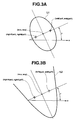
- the outline generator 4c calculates an inclination angle of the face towards x direction based on expression (1) shown below (see FIG. 3A ).
- delta_x denotes a distance between the right and left eyes in x direction
- delta_y denotes a distance between the eyes in y direction.
- ⁇ arctan abs delta_x , abs delta_y
- delta_x is derived from “rightEyeX - leftEyeX” and delta_y is derived from “rightEyeY - leftEyeY”.
- the outline generator 4c calculates a distance "dis_lr_eye” between the right and left eyes from expression (2) using delta_x and delta_y (see FIG. 2 ).
- dis_lr_eye sqrt ⁇ delta_ x 2 + delta_ y 2
- the outline generator 4c derives the pseudo outline L1 from expression (3) based on coordinates (wcx, wcy) of a middle point between the right and left eyes, the inclination angle ⁇ and distance dis_lr_eye, under the assumption that the pseudo outline L1 will be formed as an ellipse (see FIG. 3A ).
- L ⁇ 1 w - wcx * cos ⁇ + y - wcy * sin ⁇ b * x - wcx * cos ⁇ + y - wcy * sin ⁇ b + - x - wcx * sin ⁇ + y - wcy * cos ⁇ a * - x - wcx * sin ⁇ + y - wcy * cos ⁇ a
- the CPU 11 and the outline generator 4c function as means for generating the pseudo outline L1 of the face based on the characteristic part(s) (the eyes, for example) detected by the face detector 4a.
- the image processor 4 corrects the face image based on the pseudo outline L1 under the control of the CPU 11.
- the image processor 4 executes warp processing which transforms an area below the right and left eyes in the face based on the pseudo outline L1.
- the image processor 4 includes a moving-distance map generator 4d.
- the moving-distance map generator 4d calculates a distance between the pseudo outline L1 and a pixel in the face image, and based on the calculated distance, generates a moving-distance map, i.e. map(x, y), which defines a moving distance for the pixel to be moved in the warp processing.
- the moving-distance map is set to have the same size as the frame which is transferred from the capturing controller, for example, 640 ⁇ 480 pixels in VGA size.
- the moving-distance map defines moving distances for each pixel in x and y directions.
- the moving-distance map defining a moving distance for each pixel in x direction is generated to decrease a calculation amount and to accelerate the processing.
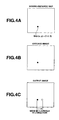
- each pixel in the image is moved based on the moving-distance map (x, y) (see FIG. 4A ), and a desired output image (see FIG. 4C ) is provided.
- map (x, y) (1.4, 0)
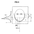
- the moving-distance map generator 4d calculates distance deltaX from the pseudo outline L1 in x direction based on expression (4) for each pixel in the face image. Then, the moving-distance map generator 4d calculates x-axis coefficient "gw_x" for each pixel from expression (5) based on the calculated distance "deltaX” and variance ⁇ X of Gaussian distribution (see FIG. 5 ).
- the variance ⁇ X is proportional to a product of the distance dis_lr_eye and an adjustment coefficient kx.
- the variance ⁇ X is varied in dependence upon the distance dis_lr_eye between the eyes. Therefore, the x-axis coefficient "gw_x" can be automatically adjusted depending on the distance dis_lr_eye, i.e., the size of the face.
- the adjustment coefficient kx may be set based on an image correction level or magnitude (described later) which is input in response to an operation made by a user with the operation input device 8.
- the moving-distance map generator 4d calculates distance deltaY from a middle line m which passes a chin to a middle position between the eyes in y direction for each pixel. Then, the moving-distance map generator 4d calculates y-axis coefficient "gw_y" for each pixel from expression (6) based on the calculated distance "deltaY” and variance ⁇ Y of Gaussian distribution (see FIG. 5 ).
- gw_y exp - 0.5 * deltaY 2 / 2 ⁇ ⁇ Y 2 where, ⁇ Y ⁇ dis_lr_eye * ky
- the variance ⁇ Y is proportional to a product of the distance dis_lr_eye and an adjustment coefficient ky.
- the variance ⁇ Y is varied in dependence upon distance dis_lr_eye between the eyes. Therefore, the y-axis coefficient "gw_y" can be automatically adjusted depending on the distance dis_lr_eye, i.e., the size of the face.
- the adjustment coefficient ky may be set based on an image correction level or magnitude (described later) which is input in response to an operation made by a user with the operation input device 8.
- the moving-distance map generator 4d defines a moving distance in x direction for each pixel depending on the x-axis coefficient gw_x and the y-axis coefficient gw_y, namely, depending on the distance deltaX from the pseudo outline L1 in x direction and the distance deltaY from the middle line m in y direction.
- a pixel which is more distant from the pseudo counter L1 in x direction is set to be moved by a shorter distance (see FIGS. 5 and 6 ), and a pixel which is more distant from the middle line m in y direction is set to be moved by a shorter distance.
- the moving-distance map generator 4d generates the moving-distance map, map (x, y), in dependence upon a position in x direction for each pixel with respect to coordinates (wcx, wcy) of the middle point between the right and left eyes.
- the moving-distance map generator 4d calculates an x component of map(x, y) from expression (7) shown below.
- the moving-distance map generator 4d derives the x component of map(x, y) by subtracting a product of the x-axis coefficient gw_x and the y-axis coefficient gw_y from the x coordinate of the pixel.
- the moving-distance map generator 4d calculates the x component of map(x, y) from expression (8) shown below.
- the moving-distance map generator 4d derives the x component of map(x, y) by adding the product of the x-axis coefficient gw_x and the y-axis coefficient gw_y to the x coordinate of the pixel.
- the moving distance map, map(x, y) may be generated so that the position of the pixel in the entered image is identical with the position of the pixel in the output image.
- the moving-distance map generator 4d can generate the moving-distance map, map(x, y), so that a shorter moving-distance is assigned to a more distant pixel from the pseudo outline L1 in x direction.
- moving distances of pixels in a portion A of the pseudo outline L1 representing a part of a left cheek and the vicinity thereof are schematically denoted by lengths and directions of arrows.
- a longer arrow denotes a larger moving distance.
- the image processor 4 executes the warp processing on the pixels based on the moving distances defined by the moving-distance map(x, y) generated by the moving-distance map generator 4d.
- a pixel having a larger x coordinate value than the x coordinate wcx of the middle point between the eyes i.e., x > wcx
- a pixel having a smaller x coordinate value than the x coordinate wcx of the middle point between the eyes i.e., x ⁇ wcx
- the warp processing transforms the image of the face so that the portion below the eyes can be slimmed.
- the level of the transformation of the face image is varied in accordance with an image correction level set by an operation made by the user with the operation input device 8.
- the warp processing is herein described as an example to transform the image of the face; however, the invention is not so limited.
- the CPU 11 and the image processor 4 functions as means for correcting the face image based on the pseudo outline L1.
- the storage medium 5 includes a non-volatile memory (flash memory) and the like.
- the storage medium 5 stores image data which is encoded by a JPEG encoder in the image processor 4.
- the storage medium 5 stores image data which is subjected to image correction processing.
- the display controller 7 reads image data which is temporarily stored in the data memory 9 to be displayed, and causes the display device 6 to display the read image data.
- the display controller 7 includes a VRAM, a VRAM controller and a digital video encoder.
- the digital video encoder periodically reads, via the VRAM controller, the luminance signal Y and the color difference signals Cb and Cr, which are read from the data memory 9 and stored in the VRAM under the control of the CPU 11.
- the digital video encoder generates a video signal based on the read signals and outputs the video signal to the display device 6.
- the display device 6 displays an image which is captured by the electronic capture unit 2 based on the video signal sent from the display controller 7. In an image capture mode, the display device 6 sequentially displays the frames generated by the capturing controller 3 as a live-view image, and displays a REC-view image which is captured as an image to be recorded.
- the operation input device 8 is used to enter an operation instruction into the image capture apparatus 100.
- the operation input device 8 includes a shutter button to give an instruction to capture an image, a menu button to give an instruction to display a menu screen which is associated with function selection and display setting, a selection button to give an instruction to select an operation mode and to set the selected mode, and a zoom button to give an instruction to adjust a zoom magnitude.
- the operation input device 8 outputs an operation signal to the CPU 11 in response to an operation made by the buttons.
- the selection button is operated to enter a setting instruction for an image correction level (or processing magnitude; from level 1 to level 3, for example) on the menu screen which is displayed in response to the operation made by the menu button.
- the operation input device 8 outputs a setting signal to the CPU 11 in response to the operation.
- the CPU 11 sets the image correction level in accordance with the entered setting signal.
- the operation input device 8 and the CPU 11 function as means for setting the processing level of the image correction processing.
- the CPU 11 controls the respective units in the image capture apparatus 100. That is, the CPU 11 controls the units in accordance with various programs for the image capture apparatus 100 stored in the program memory 10.
- the data memory 9 includes, for example, a flash memory or the like and temporarily stores data to be processed by the CPU 11.
- the program memory 10 stores various programs and data required for the CPU 11 to operate.
- a program stored in the program memory 10 includes a face detection control routine, an eye detection control routine, an outline generation control routine and a correction control routine.
- routine means a set of instructions which constitute a part of a computer program and realize a certain function.
- the face detection control routine includes a set of instructions which cause the CPU 11 to realize a function for making the face detector 4a detect a characteristic part (face part) such as an eye, a nose, or a mouth from the frame generated by the electronic capture unit 2, and detect a face.
- a characteristic part face part
- the eye detection control routine includes a set of instructions which cause the CPU 11 to realize a function for making the eye detector 4b detect eyes in the face which are detected by the face detector 4a.
- the outline generation control routine includes a set of instructions for causing the CPU 11 to realize a function for making the outline generator 4c generate a pseudo outline L1 of the face based on the characteristic parts such as the eyes of the face detected by the face detector 4a.
- the CPU 11 causes the outline generator 4c to calculate an inclination angle of the face and a distance between the eyes based on the positions of the eyes detected by the eye detector 4b.
- the CPU 11 causes the outline generator 4c to generate the pseudo outline L1 of the face based on the calculation result.
- the correction control routine includes a set of instructions for causing the CPU 11 to realize a function for making the image processor 4 execute correction processing on the face image based on the pseudo outline L1 generated by the outline generator 4c.
- the CPU 11 causes the image processor 4 to execute the warp processing to transform the face image based on the pseudo outline L1. That is, the CPU 11 causes the moving-distance map generator 4d to calculate a distance from the pseudo outline L1 for each pixel in the face image, and causes the moving-distance map generator 4d to generate a moving-distance map, which defines a moving distance for each pixel, based on the calculated distance. Then, the CPU 11 causes the image processor 4 to execute the warp processing on the face image based on the moving-distance given from the moving-distance map.
- FIG. 7 is a flowchart showing an operation example according to the image correction processing.
- the image correction processing is executed in response to an operation which is made by the user with the operation input device 8 to select an image correction mode on the menu screen.
- the CPU 11 causes the capturing controller 3 to adjust a focus condition, an exposure condition and a white balance, and causes the electronic capture unit 2 to capture the face image as the subject (step S1).
- the capturing controller 3 reads a frame of the face image from the image-capture range of the electronic capture unit 2 and outputs the frame to the image processor 4.
- the CPU 11 causes the face detector 4a to detect the characteristic parts such as the eyes, nose, or mouth from the frame of the face image, and to detect the face based on the characteristic parts (step S2).
- the CPU 11 causes the eye detector 4b to detect the coordinates (rightEyeX, rightEyeY) and (leftEyeX, leftEye Y) of the centers of the right and left eyes in the face detected by the face detector 4a (step S3).
- ⁇ arctan abs delta_x
- abs delta_y dis_lr_eye sqrt ⁇ delta_ x 2 + delta_ y 2
- the CPU 11 causes the outline generator 4c to generate the pseudo outline L1 based on the coordinates (wcx, wcy) of the center point between the eyes, the inclination angle ⁇ of the face, and the distance dis_lr_eye between the eyes using the expression (3) (step S5).
- L ⁇ 1 w - wcx * cos ⁇ + y - wcy * sin ⁇ b * x - wcx * cos ⁇ + y - wcy * sin ⁇ b + - x - wcx * sin ⁇ + y - wcy * cos ⁇ a * - x - wcx * sin ⁇ + y - wcy * cos ⁇ a
- the CPU 11 causes the moving-distance map generator 4d to calculate a distance from the pseudo outline L1 for each pixel in the face image, and causes the moving-distance map generator 4d to generate the moving-distance map, i.e., map(x, y), which defines a moving-distance for each pixel based on the calculated distance from the pseudo outline L1 (step S6).
- the CPU 11 causes the moving-distance map generator 4d to calculate a distance deltaX from the pseudo outline L1 in x direction based on the expression (4) for each pixel in the face image. Then the CPU 11 causes the moving-distance map generator 4d to calculate an x-axis coefficient gw_x, which is associated with the moving distance in x direction for each pixel, based on the distance deltaX in x direction and the variance ⁇ X of Gaussian distribution using the exponential function shown in the expression (5).
- the CPU 11 causes the moving-distance map generator 4d to calculate the distance deltaY in y direction from the middle line m which passes the middle position between the chin and the eyes. Then, the CPU 11 causes the moving-distance map generator 4d to calculate a y-axis coefficient gw_y, which is associated with the moving distance in y direction for each pixel, based on the distance deltaY in y direction and the variance oY of Gaussian distribution using the exponential function shown in the expression (6).
- gw_y exp - 0.5 * deltaY 2 / 2 ⁇ ⁇ Y 2 where, ⁇ Y ⁇ dis_lr_eye ⁇ ky
- the CPU 11 causes the moving-distance map generator 4d to calculate an x component of map(x, y) based on expression (7) by subtracting a product of the x-axis coefficient gw_x and the y-axis coefficient gw_y from the x coordinate of the pixel.
- the CPU 11 causes the moving-distance map generator 4d to calculate the x component of map(x, y) based on expression (8) by adding the product of the x-axis coefficient gw_x and the y-axis coefficient gw_y to the x coordinate of the pixel.
- the CPU 11 causes the image processor 4 to execute the warp processing on each pixel depending on the moving distance of the pixel defined by the moving distance map, map(x, y), to correct the face image in such a manner that a pixel having a larger x coordinate value than the x coordinate wcx of the middle point between the eyes (i.e., x > wcx) is moved to the left by the moving distance, and a pixel having a smaller x coordinate value than wcx (i.e., x ⁇ wcx) is moved to the right by the moving distance (step S7).
- the CPU 11 stores the image data of the image corrected by the warp processing into the storage medium 5 (step S8), and then, terminates the image correction processing.
- a characteristic part of a face in a face image captured by the electronic capture unit 2 is detected, and pseudo outline L1 of the face can be generated based on the characteristic part.
- position coordinates (rightEyeX, rightEyeY) and (leftEyeX, leftEyeY) of the eyes are detected.
- a face inclination angle ⁇ and a distance dis_lr_eye between the right and left eyes are calculated based on the detected position coordinates (rightEyeX, rightEyeY) and (leftEyeX, leftEyeY).
- a pseudo outline L1 of the face can be generated. Therefore, detection of the characteristic part in the face and calculation of the inclination angle ⁇ of the face and the distance between the eyes dis_lr_eye can appropriately be executed.
- the pseudo outline L1 of the face can appropriately generated based on the characteristic part.
- correction processing can be executed on the captured face image. That is, warp processing to transform the face image can be executed based on the pseudo outline L1 of the face. Specifically, distances between the pseudo outline L1 and pixels in the face image are calculated, and a moving-distance map, map(x, y), which defines moving distances for the pixels, are generated based on the calculated distances. The warp processing is executed on the face image in accordance with the moving distances given from the moving-distance map. Therefore, the correction processing can appropriately be executed on the face image based on the pseudo outline L1.
- correction on the face image can be performed so that an outline below eyes in the face can be slimmed.
- the user does not need to make a special operation for image correction, and the image correction for the face image can readily executed.
- a level of the image correction is set by a predetermined operation made by the user with the operation input unit 8.
- the correction processing is executed on the face image in dependence upon the image correction level.
- processing magnitude that is, how much the face is slimmed, can be set to a level desired by the user, and the image capture apparatus 100 can be further useful.
- whether to or not to execute the image correction processing may be determined based on a size of the face detected by the face detection.
- the pseudo outline L1 of the face may not necessarily be generated if the detected face does not fall within a predetermined area and the size of the face is larger or smaller than a predetermined value, or if the distance between the eyes is larger or smaller than a predetermined value. Thus, excessive image correction is not executed.
- the moving-distance in x direction may be changed in dependence upon the size of the detected face.
- the moving-distance in x direction may be changed by changing the x-axis coefficient gw_x derived from the expression (5) by changing the adjustment coefficient kx, or by multiplying the x-axis coefficient gw_x by a predetermined coefficient, so that the moving-distance is more enlarged when larger face is detected.
- the image correction processing can appropriately be executed in consideration of the size of the face with respect to the image size.
- the eyes are detected as the characteristic parts.
- the nose, mouth or eye brows may be detected as the characteristic part(s).
- the pseudo outline L1 is generated on the basis of the positions of the eyes.
- the pseudo outline L1 may be generated on the basis of any characteristic part in the face.
- the pseudo outline L1 may be generated on the basis of one or more of the positions of the nose, mouth and the like.
- pseudo outline L1 By generating the pseudo outline L1 on the basis of the positions of the nose, mouse and the like in addition to the eyes, more precise pseudo outline L1 can be generated. Thus, the image correction processing can be more appropriately executed.
- the pseudo outline L1 is generated on the basis of the positions of the eyes.
- the pseudo outline L1 may be generated on the basis of the sizes of the eyes in addition to the positions of the eyes. That is, the eye detector 4b may calculate the sizes of the eyes as well as the positions of the eyes, and the pseudo outline L1 may be generated based on the positions and sizes of the eyes.
- the shape of the pseudo outline L1 is assumed to be ellipse.
- the pseudo outline of the face is not limited to the ellipse shape.
- the pseudo outline L1 may be any curve that traces the outline of the face.
- appropriate image correction can be executed on the face image using the pseudo outline L2.
- image correction is executed so that the portion below the eyes is slimmed.
- the invention is not so limited. For example, if an x coordinate of a pixel is larger than the x coordinate of the middle point between the eyes (i.e., when x > wcx), an x component of map(x, y) may be calculated from the expression (8). As well, if an x coordinate of a pixel is smaller than the x coordinate of the center of the eyes, an x component of map(x, y) may be calculated from the expression (7). Thus, the image correction may be executed so that the portion below the eyes is widened.
- an age of the subject person may be estimated, and the pseudo outline L1 may be generated in consideration of the estimated age. For example, since the positions of the eyes of a child are lower than the positions of the eyes of an adult, considering the age of the subject person allows more accurately generating the pseudo outline L1.
- the pseudo outline L1 of the face may be generated in view of sexuality or race of the subject person.
- the correction processing may be executed on the live-view image, and a corrected image may be displayed as the live-view image. That is, the moving distance map, map(x, y) is generated and the sequentially entered live-view image is corrected based on map(x, y).
- the corrected image is displayed as the live-view image.
- the user can operate the operation input device 8 to adjust the level of the image correction.
- the face image corrected in dependence upon the adjusted level of the image correction is displayed as the live-view image. Therefore, the user can view the face image corrected at the set level of the image correction, before recording the image. Thereafter, when the shutter button of the operation input device 8 is depressed, an image to be recorded is captured and the correction processing is executed at the image correction level set during the live-view display, and the image subjected to the correction is recorded in a storage medium.
- the above configuration of the image capture apparatus 100 is illustrated by way of example, and the configuration of the image capture apparatus 100 is not limited to the illustrated example.
- the image capture apparatus 100 is described as an example of the image processing apparatus. However, a different image processing apparatus may be utilized.
- the imaging lens unit 1, the electronic capture unit 2, and the capturing controller 3 may necessarily not be provided.
- the present invention can be applied to any image processing apparatus, which can acquire a face image, detect a characteristic part in the face image, generate a pseudo outline of a face based on the characteristic part, and execute correction processing on the face image based on the pseudo outline.
- the present invention may be applied to a computer system such as a personal computer.
- the face detection function, the characteristic part detection function, the outline generation function, and the image correction function are realized by the image processor 4 (face detector 4a, eye detector 4b, outline generator 4c and moving-distance map generator) under the control of the CPU 11.
- the image processor 4 face detector 4a, eye detector 4b, outline generator 4c and moving-distance map generator
- the invention is not so limited.
- the functions may be presented by the CPU 11 executing predetermined programs stored in a storage medium.
Landscapes
- Engineering & Computer Science (AREA)
- Physics & Mathematics (AREA)
- Theoretical Computer Science (AREA)
- General Physics & Mathematics (AREA)
- Oral & Maxillofacial Surgery (AREA)
- Health & Medical Sciences (AREA)
- Multimedia (AREA)
- General Health & Medical Sciences (AREA)
- Human Computer Interaction (AREA)
- Geometry (AREA)
- Signal Processing (AREA)
- Computer Vision & Pattern Recognition (AREA)
- Image Processing (AREA)
- Studio Devices (AREA)
- Image Analysis (AREA)
Applications Claiming Priority (2)
| Application Number | Priority Date | Filing Date | Title |
|---|---|---|---|
| JP2008303706 | 2008-11-28 | ||
| JP2009242517A JP4862934B2 (ja) | 2008-11-28 | 2009-10-21 | 画像処理装置、画像処理方法及びプログラム |
Publications (2)
| Publication Number | Publication Date |
|---|---|
| EP2192544A1 EP2192544A1 (en) | 2010-06-02 |
| EP2192544B1 true EP2192544B1 (en) | 2013-01-02 |
Family
ID=41785700
Family Applications (1)
| Application Number | Title | Priority Date | Filing Date |
|---|---|---|---|
| EP09177131A Active EP2192544B1 (en) | 2008-11-28 | 2009-11-26 | Image processing apparatus and image processing method for correcting face image |
Country Status (6)
| Country | Link |
|---|---|
| US (1) | US8411911B2 (ko) |
| EP (1) | EP2192544B1 (ko) |
| JP (1) | JP4862934B2 (ko) |
| KR (1) | KR101036858B1 (ko) |
| CN (1) | CN101902577A (ko) |
| TW (1) | TWI390453B (ko) |
Families Citing this family (16)
| Publication number | Priority date | Publication date | Assignee | Title |
|---|---|---|---|---|
| TWI447658B (zh) * | 2010-03-24 | 2014-08-01 | Ind Tech Res Inst | 人臉影像擷取方法與裝置 |
| TWI413019B (zh) * | 2010-12-07 | 2013-10-21 | Novatek Microelectronics Corp | 影像調整電路及影像調整方法 |
| CN102572453A (zh) * | 2010-12-17 | 2012-07-11 | 联咏科技股份有限公司 | 影像调整电路及影像调整方法 |
| JP2013005091A (ja) * | 2011-06-14 | 2013-01-07 | Pentax Ricoh Imaging Co Ltd | 撮像装置および距離情報取得方法 |
| JP2013098840A (ja) * | 2011-11-02 | 2013-05-20 | Sony Corp | 情報処理装置、表示制御方法およびプログラム |
| KR101977638B1 (ko) * | 2012-02-29 | 2019-05-14 | 삼성전자주식회사 | 영상 내 사용자의 시선 보정 방법, 기계로 읽을 수 있는 저장 매체 및 통신 단말 |
| JP5450739B2 (ja) * | 2012-08-30 | 2014-03-26 | シャープ株式会社 | 画像処理装置及び画像表示装置 |
| US9417666B2 (en) | 2012-10-19 | 2016-08-16 | Microsoft Technology Licesning, LLC | User and device movement based display compensation |
| CN104866807B (zh) * | 2014-02-24 | 2019-09-13 | 腾讯科技(深圳)有限公司 | 一种人脸定位方法及系统 |
| JP6311372B2 (ja) | 2014-03-13 | 2018-04-18 | オムロン株式会社 | 画像処理装置および画像処理方法 |
| CN104123543B (zh) * | 2014-07-23 | 2018-11-27 | 泰亿格电子(上海)有限公司 | 一种基于人脸识别的眼球运动识别方法 |
| JP6201938B2 (ja) * | 2014-09-09 | 2017-09-27 | カシオ計算機株式会社 | 画像補正装置、画像補正方法及びプログラム |
| JP6846440B2 (ja) * | 2016-12-27 | 2021-03-24 | シャープ株式会社 | 画像処理装置、画像印刷装置、撮像装置、および画像処理プログラム |
| CN107730449B (zh) * | 2017-11-07 | 2021-12-14 | 深圳市云之梦科技有限公司 | 一种人脸五官美化处理的方法及系统 |
| CN108833771A (zh) * | 2018-05-23 | 2018-11-16 | 广州美人信息技术有限公司 | 一种人像构图线生成方法、系统及装置 |
| CN110555794B (zh) * | 2018-05-31 | 2021-07-23 | 北京市商汤科技开发有限公司 | 图像处理方法及装置、电子设备和存储介质 |
Family Cites Families (11)
| Publication number | Priority date | Publication date | Assignee | Title |
|---|---|---|---|---|
| JP2001209817A (ja) * | 2000-01-27 | 2001-08-03 | Fujimikku:Kk | 顔面画像の修正方法およびそのための装置 |
| US7155036B2 (en) * | 2000-12-04 | 2006-12-26 | Sony Corporation | Face detection under varying rotation |
| JP2002175538A (ja) * | 2000-12-08 | 2002-06-21 | Mitsubishi Electric Corp | 似顔絵生成装置及び似顔絵生成方法及び似顔絵生成プログラムを記録した記録媒体及び通信用端末及び通信用端末による通信方法 |
| US6845171B2 (en) * | 2001-11-19 | 2005-01-18 | Microsoft Corporation | Automatic sketch generation |
| JP3855939B2 (ja) | 2003-01-31 | 2006-12-13 | ソニー株式会社 | 画像処理装置、画像処理方法及び撮影装置 |
| JP2004318204A (ja) * | 2003-04-10 | 2004-11-11 | Sony Corp | 画像処理装置、画像処理方法及び撮影装置 |
| JP4403497B2 (ja) | 2004-03-24 | 2010-01-27 | フリュー株式会社 | 写真シール販売機および写真シール作成方法、並びにプログラム |
| CN100397410C (zh) | 2005-12-31 | 2008-06-25 | 北京中星微电子有限公司 | 基于视频的面部表情识别方法及装置 |
| JP2007272435A (ja) * | 2006-03-30 | 2007-10-18 | Univ Of Electro-Communications | 顔特徴抽出装置及び顔特徴抽出方法 |
| JP2008242912A (ja) | 2007-03-28 | 2008-10-09 | Nomura Securities Co Ltd | 口座開設システム、業務処理サーバ、プログラム、及び記録媒体 |
| JP4389954B2 (ja) | 2007-03-29 | 2009-12-24 | セイコーエプソン株式会社 | 画像処理装置、画像処理方法、コンピュータープログラム、記録媒体、および、プリンタ |
-
2009
- 2009-10-21 JP JP2009242517A patent/JP4862934B2/ja active Active
- 2009-11-24 US US12/624,743 patent/US8411911B2/en active Active
- 2009-11-25 KR KR1020090114468A patent/KR101036858B1/ko active IP Right Grant
- 2009-11-26 CN CN2009102666001A patent/CN101902577A/zh active Pending
- 2009-11-26 EP EP09177131A patent/EP2192544B1/en active Active
- 2009-11-27 TW TW098140526A patent/TWI390453B/zh not_active IP Right Cessation
Also Published As
| Publication number | Publication date |
|---|---|
| EP2192544A1 (en) | 2010-06-02 |
| KR101036858B1 (ko) | 2011-05-25 |
| TW201030632A (en) | 2010-08-16 |
| KR20100061361A (ko) | 2010-06-07 |
| US20100135532A1 (en) | 2010-06-03 |
| TWI390453B (zh) | 2013-03-21 |
| JP2010152871A (ja) | 2010-07-08 |
| US8411911B2 (en) | 2013-04-02 |
| JP4862934B2 (ja) | 2012-01-25 |
| CN101902577A (zh) | 2010-12-01 |
Similar Documents
| Publication | Publication Date | Title |
|---|---|---|
| EP2192544B1 (en) | Image processing apparatus and image processing method for correcting face image | |
| US8953053B2 (en) | Image processing apparatus, image pickup apparatus, and image processing method | |
| US8767036B2 (en) | Panoramic imaging apparatus, imaging method, and program with warning detection | |
| US8228383B2 (en) | Image pickup apparatus and method for controlling ranging area based on detected object | |
| US8934040B2 (en) | Imaging device capable of setting a focus detection region and imaging method for imaging device | |
| US20100085422A1 (en) | Imaging apparatus, imaging method, and program | |
| JP4732303B2 (ja) | 撮像装置 | |
| US9269131B2 (en) | Image processing apparatus with function of geometrically deforming image, image processing method therefor, and storage medium | |
| JP4752941B2 (ja) | 画像合成装置及びプログラム | |
| US20090231628A1 (en) | Image Processing Apparatus, Image Processing Method, Computer Program for Image Processing | |
| US20090028390A1 (en) | Image Processing for Estimating Subject Distance | |
| KR101475684B1 (ko) | 디지털 영상 처리기에서 얼굴 영상 개선 장치 및 방법 | |
| KR100844129B1 (ko) | 카메라를 이용한 마우스 인터페이스 장치, 이 장치에 의한시스템 및 방법, 그리고 이를 실현하기 위한 컴퓨터로 읽을수 있는 기록매체 | |
| JP4953770B2 (ja) | 撮像装置 | |
| US9143684B2 (en) | Digital photographing apparatus, method of controlling the same, and computer-readable storage medium | |
| JP5393877B2 (ja) | 撮像装置および集積回路 | |
| KR101738433B1 (ko) | 손떨림에 의한 데이터 왜곡 보정기능을 구비한 핸드핼드/모바일용 3d 스캔 장치 및 그 보정 방법 | |
| JP2009223524A (ja) | 画像処理装置、画像処理方法、画像処理のためのコンピュータプログラム | |
| JP4871315B2 (ja) | 複眼撮影装置およびその制御方法並びにプログラム | |
| JP6257260B2 (ja) | 撮像装置及びその制御方法 | |
| JP5279453B2 (ja) | 画像振れ補正装置、撮像装置及び画像振れ補正方法 | |
| JP2014056169A (ja) | 焦点調節装置及び焦点調節方法 | |
| JP6257289B2 (ja) | 画像処理装置およびそれを備えた撮像装置、画像処理方法 | |
| JP6885133B2 (ja) | 画像処理装置、撮像システム、画像処理方法及びプログラム | |
| US20090232402A1 (en) | Image Processing Apparatus, Image Processing Method, and Computer Program for Image Processing |
Legal Events
| Date | Code | Title | Description |
|---|---|---|---|
| PUAI | Public reference made under article 153(3) epc to a published international application that has entered the european phase |
Free format text: ORIGINAL CODE: 0009012 |
|
| 17P | Request for examination filed |
Effective date: 20091126 |
|
| AK | Designated contracting states |
Kind code of ref document: A1 Designated state(s): AT BE BG CH CY CZ DE DK EE ES FI FR GB GR HR HU IE IS IT LI LT LU LV MC MK MT NL NO PL PT RO SE SI SK SM TR |
|
| AX | Request for extension of the european patent |
Extension state: AL BA RS |
|
| 17Q | First examination report despatched |
Effective date: 20100804 |
|
| GRAP | Despatch of communication of intention to grant a patent |
Free format text: ORIGINAL CODE: EPIDOSNIGR1 |
|
| GRAS | Grant fee paid |
Free format text: ORIGINAL CODE: EPIDOSNIGR3 |
|
| GRAA | (expected) grant |
Free format text: ORIGINAL CODE: 0009210 |
|
| AK | Designated contracting states |
Kind code of ref document: B1 Designated state(s): AT BE BG CH CY CZ DE DK EE ES FI FR GB GR HR HU IE IS IT LI LT LU LV MC MK MT NL NO PL PT RO SE SI SK SM TR |
|
| REG | Reference to a national code |
Ref country code: GB Ref legal event code: FG4D |
|
| REG | Reference to a national code |
Ref country code: AT Ref legal event code: REF Ref document number: 591964 Country of ref document: AT Kind code of ref document: T Effective date: 20130115 Ref country code: CH Ref legal event code: EP |
|
| REG | Reference to a national code |
Ref country code: IE Ref legal event code: FG4D |
|
| REG | Reference to a national code |
Ref country code: DE Ref legal event code: R096 Ref document number: 602009012408 Country of ref document: DE Effective date: 20130228 |
|
| REG | Reference to a national code |
Ref country code: AT Ref legal event code: MK05 Ref document number: 591964 Country of ref document: AT Kind code of ref document: T Effective date: 20130102 |
|
| REG | Reference to a national code |
Ref country code: NL Ref legal event code: VDEP Effective date: 20130102 |
|
| PG25 | Lapsed in a contracting state [announced via postgrant information from national office to epo] |
Ref country code: SI Free format text: LAPSE BECAUSE OF FAILURE TO SUBMIT A TRANSLATION OF THE DESCRIPTION OR TO PAY THE FEE WITHIN THE PRESCRIBED TIME-LIMIT Effective date: 20130102 |
|
| REG | Reference to a national code |
Ref country code: LT Ref legal event code: MG4D |
|
| PG25 | Lapsed in a contracting state [announced via postgrant information from national office to epo] |
Ref country code: BG Free format text: LAPSE BECAUSE OF FAILURE TO SUBMIT A TRANSLATION OF THE DESCRIPTION OR TO PAY THE FEE WITHIN THE PRESCRIBED TIME-LIMIT Effective date: 20130402 Ref country code: SE Free format text: LAPSE BECAUSE OF FAILURE TO SUBMIT A TRANSLATION OF THE DESCRIPTION OR TO PAY THE FEE WITHIN THE PRESCRIBED TIME-LIMIT Effective date: 20130102 Ref country code: BE Free format text: LAPSE BECAUSE OF FAILURE TO SUBMIT A TRANSLATION OF THE DESCRIPTION OR TO PAY THE FEE WITHIN THE PRESCRIBED TIME-LIMIT Effective date: 20130102 Ref country code: LT Free format text: LAPSE BECAUSE OF FAILURE TO SUBMIT A TRANSLATION OF THE DESCRIPTION OR TO PAY THE FEE WITHIN THE PRESCRIBED TIME-LIMIT Effective date: 20130102 Ref country code: AT Free format text: LAPSE BECAUSE OF FAILURE TO SUBMIT A TRANSLATION OF THE DESCRIPTION OR TO PAY THE FEE WITHIN THE PRESCRIBED TIME-LIMIT Effective date: 20130102 Ref country code: CZ Free format text: LAPSE BECAUSE OF FAILURE TO SUBMIT A TRANSLATION OF THE DESCRIPTION OR TO PAY THE FEE WITHIN THE PRESCRIBED TIME-LIMIT Effective date: 20130102 Ref country code: IS Free format text: LAPSE BECAUSE OF FAILURE TO SUBMIT A TRANSLATION OF THE DESCRIPTION OR TO PAY THE FEE WITHIN THE PRESCRIBED TIME-LIMIT Effective date: 20130502 Ref country code: NO Free format text: LAPSE BECAUSE OF FAILURE TO SUBMIT A TRANSLATION OF THE DESCRIPTION OR TO PAY THE FEE WITHIN THE PRESCRIBED TIME-LIMIT Effective date: 20130402 Ref country code: ES Free format text: LAPSE BECAUSE OF FAILURE TO SUBMIT A TRANSLATION OF THE DESCRIPTION OR TO PAY THE FEE WITHIN THE PRESCRIBED TIME-LIMIT Effective date: 20130413 |
|
| PG25 | Lapsed in a contracting state [announced via postgrant information from national office to epo] |
Ref country code: FI Free format text: LAPSE BECAUSE OF FAILURE TO SUBMIT A TRANSLATION OF THE DESCRIPTION OR TO PAY THE FEE WITHIN THE PRESCRIBED TIME-LIMIT Effective date: 20130102 Ref country code: PL Free format text: LAPSE BECAUSE OF FAILURE TO SUBMIT A TRANSLATION OF THE DESCRIPTION OR TO PAY THE FEE WITHIN THE PRESCRIBED TIME-LIMIT Effective date: 20130102 Ref country code: LV Free format text: LAPSE BECAUSE OF FAILURE TO SUBMIT A TRANSLATION OF THE DESCRIPTION OR TO PAY THE FEE WITHIN THE PRESCRIBED TIME-LIMIT Effective date: 20130102 Ref country code: NL Free format text: LAPSE BECAUSE OF FAILURE TO SUBMIT A TRANSLATION OF THE DESCRIPTION OR TO PAY THE FEE WITHIN THE PRESCRIBED TIME-LIMIT Effective date: 20130102 Ref country code: PT Free format text: LAPSE BECAUSE OF FAILURE TO SUBMIT A TRANSLATION OF THE DESCRIPTION OR TO PAY THE FEE WITHIN THE PRESCRIBED TIME-LIMIT Effective date: 20130502 Ref country code: GR Free format text: LAPSE BECAUSE OF FAILURE TO SUBMIT A TRANSLATION OF THE DESCRIPTION OR TO PAY THE FEE WITHIN THE PRESCRIBED TIME-LIMIT Effective date: 20130403 |
|
| PG25 | Lapsed in a contracting state [announced via postgrant information from national office to epo] |
Ref country code: HR Free format text: LAPSE BECAUSE OF FAILURE TO SUBMIT A TRANSLATION OF THE DESCRIPTION OR TO PAY THE FEE WITHIN THE PRESCRIBED TIME-LIMIT Effective date: 20130102 |
|
| PG25 | Lapsed in a contracting state [announced via postgrant information from national office to epo] |
Ref country code: DK Free format text: LAPSE BECAUSE OF FAILURE TO SUBMIT A TRANSLATION OF THE DESCRIPTION OR TO PAY THE FEE WITHIN THE PRESCRIBED TIME-LIMIT Effective date: 20130102 Ref country code: RO Free format text: LAPSE BECAUSE OF FAILURE TO SUBMIT A TRANSLATION OF THE DESCRIPTION OR TO PAY THE FEE WITHIN THE PRESCRIBED TIME-LIMIT Effective date: 20130102 Ref country code: SK Free format text: LAPSE BECAUSE OF FAILURE TO SUBMIT A TRANSLATION OF THE DESCRIPTION OR TO PAY THE FEE WITHIN THE PRESCRIBED TIME-LIMIT Effective date: 20130102 Ref country code: EE Free format text: LAPSE BECAUSE OF FAILURE TO SUBMIT A TRANSLATION OF THE DESCRIPTION OR TO PAY THE FEE WITHIN THE PRESCRIBED TIME-LIMIT Effective date: 20130102 |
|
| PLBE | No opposition filed within time limit |
Free format text: ORIGINAL CODE: 0009261 |
|
| STAA | Information on the status of an ep patent application or granted ep patent |
Free format text: STATUS: NO OPPOSITION FILED WITHIN TIME LIMIT |
|
| PG25 | Lapsed in a contracting state [announced via postgrant information from national office to epo] |
Ref country code: CY Free format text: LAPSE BECAUSE OF FAILURE TO SUBMIT A TRANSLATION OF THE DESCRIPTION OR TO PAY THE FEE WITHIN THE PRESCRIBED TIME-LIMIT Effective date: 20130102 |
|
| 26N | No opposition filed |
Effective date: 20131003 |
|
| PG25 | Lapsed in a contracting state [announced via postgrant information from national office to epo] |
Ref country code: IT Free format text: LAPSE BECAUSE OF FAILURE TO SUBMIT A TRANSLATION OF THE DESCRIPTION OR TO PAY THE FEE WITHIN THE PRESCRIBED TIME-LIMIT Effective date: 20130102 |
|
| REG | Reference to a national code |
Ref country code: DE Ref legal event code: R097 Ref document number: 602009012408 Country of ref document: DE Effective date: 20131003 |
|
| REG | Reference to a national code |
Ref country code: CH Ref legal event code: PL |
|
| PG25 | Lapsed in a contracting state [announced via postgrant information from national office to epo] |
Ref country code: MC Free format text: LAPSE BECAUSE OF FAILURE TO SUBMIT A TRANSLATION OF THE DESCRIPTION OR TO PAY THE FEE WITHIN THE PRESCRIBED TIME-LIMIT Effective date: 20130102 Ref country code: LI Free format text: LAPSE BECAUSE OF NON-PAYMENT OF DUE FEES Effective date: 20131130 Ref country code: CH Free format text: LAPSE BECAUSE OF NON-PAYMENT OF DUE FEES Effective date: 20131130 |
|
| REG | Reference to a national code |
Ref country code: IE Ref legal event code: MM4A |
|
| PG25 | Lapsed in a contracting state [announced via postgrant information from national office to epo] |
Ref country code: IE Free format text: LAPSE BECAUSE OF NON-PAYMENT OF DUE FEES Effective date: 20131126 |
|
| PG25 | Lapsed in a contracting state [announced via postgrant information from national office to epo] |
Ref country code: SM Free format text: LAPSE BECAUSE OF FAILURE TO SUBMIT A TRANSLATION OF THE DESCRIPTION OR TO PAY THE FEE WITHIN THE PRESCRIBED TIME-LIMIT Effective date: 20130102 |
|
| PG25 | Lapsed in a contracting state [announced via postgrant information from national office to epo] |
Ref country code: TR Free format text: LAPSE BECAUSE OF FAILURE TO SUBMIT A TRANSLATION OF THE DESCRIPTION OR TO PAY THE FEE WITHIN THE PRESCRIBED TIME-LIMIT Effective date: 20130102 |
|
| PG25 | Lapsed in a contracting state [announced via postgrant information from national office to epo] |
Ref country code: LU Free format text: LAPSE BECAUSE OF NON-PAYMENT OF DUE FEES Effective date: 20131126 Ref country code: HU Free format text: LAPSE BECAUSE OF FAILURE TO SUBMIT A TRANSLATION OF THE DESCRIPTION OR TO PAY THE FEE WITHIN THE PRESCRIBED TIME-LIMIT; INVALID AB INITIO Effective date: 20091126 Ref country code: MK Free format text: LAPSE BECAUSE OF FAILURE TO SUBMIT A TRANSLATION OF THE DESCRIPTION OR TO PAY THE FEE WITHIN THE PRESCRIBED TIME-LIMIT Effective date: 20130102 |
|
| PG25 | Lapsed in a contracting state [announced via postgrant information from national office to epo] |
Ref country code: MT Free format text: LAPSE BECAUSE OF FAILURE TO SUBMIT A TRANSLATION OF THE DESCRIPTION OR TO PAY THE FEE WITHIN THE PRESCRIBED TIME-LIMIT Effective date: 20130102 |
|
| REG | Reference to a national code |
Ref country code: FR Ref legal event code: PLFP Year of fee payment: 7 |
|
| REG | Reference to a national code |
Ref country code: FR Ref legal event code: PLFP Year of fee payment: 8 |
|
| REG | Reference to a national code |
Ref country code: FR Ref legal event code: PLFP Year of fee payment: 9 |
|
| REG | Reference to a national code |
Ref country code: FR Ref legal event code: PLFP Year of fee payment: 10 |
|
| PGFP | Annual fee paid to national office [announced via postgrant information from national office to epo] |
Ref country code: FR Payment date: 20191014 Year of fee payment: 11 |
|
| PGFP | Annual fee paid to national office [announced via postgrant information from national office to epo] |
Ref country code: GB Payment date: 20191122 Year of fee payment: 11 |
|
| GBPC | Gb: european patent ceased through non-payment of renewal fee |
Effective date: 20201126 |
|
| PG25 | Lapsed in a contracting state [announced via postgrant information from national office to epo] |
Ref country code: FR Free format text: LAPSE BECAUSE OF NON-PAYMENT OF DUE FEES Effective date: 20201130 |
|
| PG25 | Lapsed in a contracting state [announced via postgrant information from national office to epo] |
Ref country code: GB Free format text: LAPSE BECAUSE OF NON-PAYMENT OF DUE FEES Effective date: 20201126 |
|
| PGFP | Annual fee paid to national office [announced via postgrant information from national office to epo] |
Ref country code: DE Payment date: 20230929 Year of fee payment: 15 |