EP2192424B1 - Optischer Artikel und Verfahren zu dessen Herstellung - Google Patents
Optischer Artikel und Verfahren zu dessen Herstellung Download PDFInfo
- Publication number
- EP2192424B1 EP2192424B1 EP09177316.8A EP09177316A EP2192424B1 EP 2192424 B1 EP2192424 B1 EP 2192424B1 EP 09177316 A EP09177316 A EP 09177316A EP 2192424 B1 EP2192424 B1 EP 2192424B1
- Authority
- EP
- European Patent Office
- Prior art keywords
- functional layer
- reflectance
- layer
- interference fringes
- refractive index
- Prior art date
- Legal status (The legal status is an assumption and is not a legal conclusion. Google has not performed a legal analysis and makes no representation as to the accuracy of the status listed.)
- Active
Links
- 230000003287 optical effect Effects 0.000 title claims description 57
- 238000004519 manufacturing process Methods 0.000 title claims description 13
- 239000002346 layers by function Substances 0.000 claims description 85
- 239000000758 substrate Substances 0.000 claims description 60
- 239000010410 layer Substances 0.000 claims description 59
- 239000011247 coating layer Substances 0.000 claims description 55
- 239000004033 plastic Substances 0.000 claims description 24
- 229920003023 plastic Polymers 0.000 claims description 24
- 230000003373 anti-fouling effect Effects 0.000 claims description 14
- 238000009826 distribution Methods 0.000 description 32
- 229920005989 resin Polymers 0.000 description 32
- 239000011347 resin Substances 0.000 description 32
- 239000010408 film Substances 0.000 description 29
- 238000000576 coating method Methods 0.000 description 18
- 230000015572 biosynthetic process Effects 0.000 description 17
- VYPSYNLAJGMNEJ-UHFFFAOYSA-N silicon dioxide Inorganic materials O=[Si]=O VYPSYNLAJGMNEJ-UHFFFAOYSA-N 0.000 description 17
- 238000004088 simulation Methods 0.000 description 17
- 230000003595 spectral effect Effects 0.000 description 17
- 239000011248 coating agent Substances 0.000 description 15
- 238000001228 spectrum Methods 0.000 description 13
- 239000000463 material Substances 0.000 description 12
- 238000000034 method Methods 0.000 description 11
- 238000004364 calculation method Methods 0.000 description 10
- 239000003086 colorant Substances 0.000 description 10
- 238000005070 sampling Methods 0.000 description 10
- 239000000377 silicon dioxide Substances 0.000 description 9
- 238000011156 evaluation Methods 0.000 description 8
- 239000007788 liquid Substances 0.000 description 8
- 239000002245 particle Substances 0.000 description 8
- 239000005871 repellent Substances 0.000 description 8
- 241000282412 Homo Species 0.000 description 7
- 230000000052 comparative effect Effects 0.000 description 7
- 230000008859 change Effects 0.000 description 6
- 229910052710 silicon Inorganic materials 0.000 description 6
- JOYRKODLDBILNP-UHFFFAOYSA-N Ethyl urethane Chemical compound CCOC(N)=O JOYRKODLDBILNP-UHFFFAOYSA-N 0.000 description 5
- 230000000694 effects Effects 0.000 description 5
- 230000008447 perception Effects 0.000 description 5
- YCKRFDGAMUMZLT-UHFFFAOYSA-N Fluorine atom Chemical compound [F] YCKRFDGAMUMZLT-UHFFFAOYSA-N 0.000 description 4
- XUIMIQQOPSSXEZ-UHFFFAOYSA-N Silicon Chemical compound [Si] XUIMIQQOPSSXEZ-UHFFFAOYSA-N 0.000 description 4
- PPBRXRYQALVLMV-UHFFFAOYSA-N Styrene Chemical compound C=CC1=CC=CC=C1 PPBRXRYQALVLMV-UHFFFAOYSA-N 0.000 description 4
- MCMNRKCIXSYSNV-UHFFFAOYSA-N Zirconium dioxide Chemical compound O=[Zr]=O MCMNRKCIXSYSNV-UHFFFAOYSA-N 0.000 description 4
- -1 acryl Chemical group 0.000 description 4
- 239000008199 coating composition Substances 0.000 description 4
- 229910052731 fluorine Inorganic materials 0.000 description 4
- 239000011737 fluorine Substances 0.000 description 4
- 239000000203 mixture Substances 0.000 description 4
- 229920001225 polyester resin Polymers 0.000 description 4
- 239000010703 silicon Substances 0.000 description 4
- 239000000126 substance Substances 0.000 description 4
- 239000004593 Epoxy Substances 0.000 description 3
- 238000001035 drying Methods 0.000 description 3
- 238000003475 lamination Methods 0.000 description 3
- 238000001771 vacuum deposition Methods 0.000 description 3
- IMROMDMJAWUWLK-UHFFFAOYSA-N Ethenol Chemical compound OC=C IMROMDMJAWUWLK-UHFFFAOYSA-N 0.000 description 2
- CPLXHLVBOLITMK-UHFFFAOYSA-N Magnesium oxide Chemical compound [Mg]=O CPLXHLVBOLITMK-UHFFFAOYSA-N 0.000 description 2
- 229920000877 Melamine resin Polymers 0.000 description 2
- GWEVSGVZZGPLCZ-UHFFFAOYSA-N Titan oxide Chemical compound O=[Ti]=O GWEVSGVZZGPLCZ-UHFFFAOYSA-N 0.000 description 2
- 239000003795 chemical substances by application Substances 0.000 description 2
- 229910052681 coesite Inorganic materials 0.000 description 2
- 229920001577 copolymer Polymers 0.000 description 2
- 229910052906 cristobalite Inorganic materials 0.000 description 2
- 230000007423 decrease Effects 0.000 description 2
- 230000007850 degeneration Effects 0.000 description 2
- 238000007598 dipping method Methods 0.000 description 2
- 230000006870 function Effects 0.000 description 2
- 230000004313 glare Effects 0.000 description 2
- 239000011521 glass Substances 0.000 description 2
- JDSHMPZPIAZGSV-UHFFFAOYSA-N melamine Chemical compound NC1=NC(N)=NC(N)=N1 JDSHMPZPIAZGSV-UHFFFAOYSA-N 0.000 description 2
- ZKATWMILCYLAPD-UHFFFAOYSA-N niobium pentoxide Chemical compound O=[Nb](=O)O[Nb](=O)=O ZKATWMILCYLAPD-UHFFFAOYSA-N 0.000 description 2
- 150000003961 organosilicon compounds Chemical class 0.000 description 2
- 230000010355 oscillation Effects 0.000 description 2
- 229920002647 polyamide Polymers 0.000 description 2
- 125000002924 primary amino group Chemical group [H]N([H])* 0.000 description 2
- 230000008569 process Effects 0.000 description 2
- 230000009467 reduction Effects 0.000 description 2
- LIVNPJMFVYWSIS-UHFFFAOYSA-N silicon monoxide Chemical compound [Si-]#[O+] LIVNPJMFVYWSIS-UHFFFAOYSA-N 0.000 description 2
- 238000004528 spin coating Methods 0.000 description 2
- 229910052682 stishovite Inorganic materials 0.000 description 2
- 230000001629 suppression Effects 0.000 description 2
- 239000010409 thin film Substances 0.000 description 2
- XOLBLPGZBRYERU-UHFFFAOYSA-N tin dioxide Chemical compound O=[Sn]=O XOLBLPGZBRYERU-UHFFFAOYSA-N 0.000 description 2
- 229910052905 tridymite Inorganic materials 0.000 description 2
- 229910019714 Nb2O3 Inorganic materials 0.000 description 1
- 229910004160 TaO2 Inorganic materials 0.000 description 1
- 229910009973 Ti2O3 Inorganic materials 0.000 description 1
- 238000005299 abrasion Methods 0.000 description 1
- 150000008065 acid anhydrides Chemical class 0.000 description 1
- PNEYBMLMFCGWSK-UHFFFAOYSA-N aluminium oxide Inorganic materials [O-2].[O-2].[O-2].[Al+3].[Al+3] PNEYBMLMFCGWSK-UHFFFAOYSA-N 0.000 description 1
- 230000008901 benefit Effects 0.000 description 1
- 238000009835 boiling Methods 0.000 description 1
- CETPSERCERDGAM-UHFFFAOYSA-N ceric oxide Chemical compound O=[Ce]=O CETPSERCERDGAM-UHFFFAOYSA-N 0.000 description 1
- 229910000422 cerium(IV) oxide Inorganic materials 0.000 description 1
- 229910052593 corundum Inorganic materials 0.000 description 1
- 230000003247 decreasing effect Effects 0.000 description 1
- 230000007547 defect Effects 0.000 description 1
- 238000013461 design Methods 0.000 description 1
- 238000011161 development Methods 0.000 description 1
- NQKXFODBPINZFK-UHFFFAOYSA-N dioxotantalum Chemical compound O=[Ta]=O NQKXFODBPINZFK-UHFFFAOYSA-N 0.000 description 1
- 238000003618 dip coating Methods 0.000 description 1
- 238000004043 dyeing Methods 0.000 description 1
- 230000008030 elimination Effects 0.000 description 1
- 238000003379 elimination reaction Methods 0.000 description 1
- 230000007613 environmental effect Effects 0.000 description 1
- 230000001747 exhibiting effect Effects 0.000 description 1
- 238000010438 heat treatment Methods 0.000 description 1
- 230000001771 impaired effect Effects 0.000 description 1
- 238000007735 ion beam assisted deposition Methods 0.000 description 1
- 238000007733 ion plating Methods 0.000 description 1
- 238000010884 ion-beam technique Methods 0.000 description 1
- 238000010030 laminating Methods 0.000 description 1
- 229910001635 magnesium fluoride Inorganic materials 0.000 description 1
- 238000005259 measurement Methods 0.000 description 1
- 239000002184 metal Substances 0.000 description 1
- 229910044991 metal oxide Inorganic materials 0.000 description 1
- 150000004706 metal oxides Chemical class 0.000 description 1
- HFLAMWCKUFHSAZ-UHFFFAOYSA-N niobium dioxide Inorganic materials O=[Nb]=O HFLAMWCKUFHSAZ-UHFFFAOYSA-N 0.000 description 1
- BFRGSJVXBIWTCF-UHFFFAOYSA-N niobium monoxide Inorganic materials [Nb]=O BFRGSJVXBIWTCF-UHFFFAOYSA-N 0.000 description 1
- 239000003960 organic solvent Substances 0.000 description 1
- 239000008188 pellet Substances 0.000 description 1
- 230000000704 physical effect Effects 0.000 description 1
- 229920006267 polyester film Polymers 0.000 description 1
- 238000002360 preparation method Methods 0.000 description 1
- 230000001681 protective effect Effects 0.000 description 1
- 238000002310 reflectometry Methods 0.000 description 1
- 230000035807 sensation Effects 0.000 description 1
- 230000035939 shock Effects 0.000 description 1
- 229910000077 silane Inorganic materials 0.000 description 1
- 150000004756 silanes Chemical class 0.000 description 1
- 150000003377 silicon compounds Chemical class 0.000 description 1
- 239000002356 single layer Substances 0.000 description 1
- 239000002904 solvent Substances 0.000 description 1
- 238000004544 sputter deposition Methods 0.000 description 1
- PBCFLUZVCVVTBY-UHFFFAOYSA-N tantalum pentoxide Inorganic materials O=[Ta](=O)O[Ta](=O)=O PBCFLUZVCVVTBY-UHFFFAOYSA-N 0.000 description 1
- 239000004149 tartrazine Substances 0.000 description 1
- 229920001187 thermosetting polymer Polymers 0.000 description 1
- 230000008719 thickening Effects 0.000 description 1
- OGIDPMRJRNCKJF-UHFFFAOYSA-N titanium oxide Inorganic materials [Ti]=O OGIDPMRJRNCKJF-UHFFFAOYSA-N 0.000 description 1
- GQUJEMVIKWQAEH-UHFFFAOYSA-N titanium(III) oxide Chemical compound O=[Ti]O[Ti]=O GQUJEMVIKWQAEH-UHFFFAOYSA-N 0.000 description 1
- ZNOKGRXACCSDPY-UHFFFAOYSA-N tungsten(VI) oxide Inorganic materials O=[W](=O)=O ZNOKGRXACCSDPY-UHFFFAOYSA-N 0.000 description 1
- 238000007738 vacuum evaporation Methods 0.000 description 1
- 230000000007 visual effect Effects 0.000 description 1
- 239000002699 waste material Substances 0.000 description 1
- 229910001845 yogo sapphire Inorganic materials 0.000 description 1
- RUDFQVOCFDJEEF-UHFFFAOYSA-N yttrium(III) oxide Inorganic materials [O-2].[O-2].[O-2].[Y+3].[Y+3] RUDFQVOCFDJEEF-UHFFFAOYSA-N 0.000 description 1
Images


Classifications
-
- G—PHYSICS
- G02—OPTICS
- G02B—OPTICAL ELEMENTS, SYSTEMS OR APPARATUS
- G02B5/00—Optical elements other than lenses
- G02B5/20—Filters
- G02B5/28—Interference filters
- G02B5/285—Interference filters comprising deposited thin solid films
- G02B5/286—Interference filters comprising deposited thin solid films having four or fewer layers, e.g. for achieving a colour effect
-
- G—PHYSICS
- G02—OPTICS
- G02C—SPECTACLES; SUNGLASSES OR GOGGLES INSOFAR AS THEY HAVE THE SAME FEATURES AS SPECTACLES; CONTACT LENSES
- G02C7/00—Optical parts
- G02C7/02—Lenses; Lens systems ; Methods of designing lenses
-
- G—PHYSICS
- G02—OPTICS
- G02C—SPECTACLES; SUNGLASSES OR GOGGLES INSOFAR AS THEY HAVE THE SAME FEATURES AS SPECTACLES; CONTACT LENSES
- G02C7/00—Optical parts
- G02C7/10—Filters, e.g. for facilitating adaptation of the eyes to the dark; Sunglasses
- G02C7/108—Colouring materials
-
- G—PHYSICS
- G02—OPTICS
- G02C—SPECTACLES; SUNGLASSES OR GOGGLES INSOFAR AS THEY HAVE THE SAME FEATURES AS SPECTACLES; CONTACT LENSES
- G02C7/00—Optical parts
- G02C7/12—Polarisers
-
- G—PHYSICS
- G02—OPTICS
- G02C—SPECTACLES; SUNGLASSES OR GOGGLES INSOFAR AS THEY HAVE THE SAME FEATURES AS SPECTACLES; CONTACT LENSES
- G02C2202/00—Generic optical aspects applicable to one or more of the subgroups of G02C7/00
- G02C2202/16—Laminated or compound lenses
Definitions
- the present invention relates to an optical article with at least one side thereof facing the outside, such as a spectacle lens, and also to a method for producing the same.
- Patent Document 1 JP-A-9-113702 (Patent Document 1) describes provision of an optical article provided with a coating that has high environmental resistance and can be made transparent.
- a degeneration layer and a hard coating layer are formed on a transparent resin substrate by CVD; the degeneration layer contains at least one of Si and Ti and has a refractive index varying in the thickness direction, while the hard coating layer contains Si and O.
- the hard coating layer is described to have a thickness of not less than 0.4 ⁇ m and not more than 5 ⁇ m.
- Patent Document 2 JP-A-7-56002 (Patent Document 2) describes uniform reduction of the reflectance of a plastic board over a wide range. It is described that for this purpose, when forming a hard coating layer on a plastic board to protect the plastic board in terms of strength, the hard coating layer is formed to have substantially the same refractive index as the refractive index of the plastic board at the portion where the hard coating layer comes in contact with the plastic board, and also that the refractive index of the hard coating layer varies continuously or gradually in the thickness direction.
- Optical substrates made of plastic are lightweight as compared with glass lenses, which are one kind of optical substrates made of glass, and also have excellent formability, workability, and dyeing affinity, together with low breakability and high safety. Accordingly, they are widely used in the field of spectacle lenses.
- the plastic material (CR-39) developed by PPG Industries, U.S., in the 1940's has, as a spectacle lens material, an excellent balance of physical properties.
- the plastic material (CR-39) has been long used as a material for plastic lenses.
- the refractive index thereof is as low as 1.50, and there are problems that in the case of lenses with minus power, such a lens has a large edge thickness, while in the case of plus lenses, the thickness at the center thereof is large.
- the refractive index of the substrate has to be increased.
- the refractive index of plastic materials has been increased from 1.50 to 1.56, 1.60, 1.67, 1.70, 1.74, and 1.76, and thus materials with a high refractive index have been developed.
- plastic spectacle lenses of various refractive indexes are commercially available.
- Optical substrates made of plastic are prone to scratches.
- a layer (film) called hard coating is often formed on the surface of the substrate to prevent scratches.
- the thickness of such a hard coating is approximately 1 to 5 ⁇ m.
- Materials typically used for forming the hard coating layer are thermosetting silicon-based resins and UV-curable organic resins.
- the refractive index of these materials is about 1.50 to about 1.55.
- a thin layer is formed on a plastic substrate with a high refractive index (e.g., 1.60 or more)
- interference fringes are formed due to the difference in refractive index and nonuniformity in the thickness.
- interference fringes will not affect the optical performance of the lens itself, but they degrade the appearance or cause reflected glare. Accordingly, in order to increase the commercial value, elimination of interference fringes is desired.
- plastic lenses having a ultra-high refractive index e.g., 1.70 or more
- the resulting interference fringes are denser and more apparent.
- One method for suppressing the formation of interference fringes is to form a hard coating layer containing a metal oxide for adjusting refractive index, so that the refractive indexes of the hard coating layer and the plastic lens substrate are comparable.
- the refractive index varies in the thickness direction so that there is no or little difference in refractive index at the portion where the hard coating layer and the plastics base material are in contact with each other, thereby reducing the reflectance.
- the thickness is reduced so that the refractive index continuously varies. Accordingly, the refractive index of the surface is lowered, thereby reducing the reflectance.
- complete suppression of interference fringes requires a special hard coating to be designed, managed, and constructed for every substrate.
- a manufacturing facility is required for each case. This imposes a heavy burden on manufacturers.
- the original purpose of the hard coating layer is not to adjust the refractive index to suit a substrate, but to serve as a layer that imparts the substrate with weather resistance, abrasion resistance, and like various characteristics, as the refractive index of the layer increases, it becomes difficult to satisfy all these conditions.
- an antireflection film is formed on the hard coating layer.
- a special antireflection film also has to be designed for each case. Accordingly, even when the refractive index of a plastic lens is increased, thin, lightweight spectacle lenses and spectacles cannot necessarily be provided, and it is difficult to satisfy all the various quality characteristics.
- EP 1 494 049 A2 describes a hard coat film having a substrate film and a hard coat layer laminated on at least one side of the substrate film, wherein a reflectance of the hard coat layer at a wavelength within 400 to 600 nm has a mean ripple amplitude of 1% or less.
- JP 2007 253512 A describes an optical laminated biaxially stretched polyester film wherein the amplitude of the ripple of spectral reflectivity at a wavelength of 450 to 600 nm after a hard coat layer with a refractive index of 1,45 to 1,55 is laminated on a lamination film is 2,0% or below, hard coat adhesion force after one-hr boiling is 90% or above and the size per one oligomer particle precipitated on the lamination film after heating at 150°C for 60min in a state that the hard coat layer is not laminated on the lamination film is 30 ⁇ m 2 or below in terms of an area.
- Application EP 1 090 968 A1 discloses a spectacle lens comprising a substrate and a hardcoat layer.
- One aspect of the invention provides a spectacle lens having the features of claim 1.
- the functional layer is defined with the period Pk of reflectance R(k), whereby appearance of interference fringes can be suppressed and/or human perception of interference fringes can be suppressed.
- the period Pk of reflectance R(k) exceeds the above value, when the optical article is observed using a light source equivalent to a three band daylight fluorescent, color difference due to interference fringes is highly likely to be appreciable because of nonuniformity in the thickness of the functional layer. Such a case is thus undesirable.
- the period Pk of reflectance R(k) of the functional layer is not more than 3.03 ⁇ 10 -5 . Although color difference due to interference fringes may be slightly perceptible, the degree thereof is smaller.
- the period Pk of reflectance R(k) of the functional layer is not more than 2.08 ⁇ 10 -5 . Color difference due to interference fringes is mitigated to the degree that the difference is barely perceptible.
- the period Pk of reflectance R(k) of the functional layer is not more than 1.59 ⁇ 10 -5 . Although color difference due to interference fringes may be barely perceptible, the degree thereof is smaller.
- the period Pk of reflectance R(k) of the functional layer is not more than 1.39 ⁇ 10 -5 . Almost no color difference due to interference fringes is observable.
- the period Pk of reflectance R(k) of the functional layer is not less than 2.63 ⁇ 10 -6 .
- the period Pk of reflectance R(k) of the functional layer is not less than 5.26 ⁇ 10 -6 . Accordingly, the surface accuracy of the functional layer can be more easily achieved, and the degree of perception of color difference due to interference fringes can be reduced.
- a typical functional layer contains a hard coating layer.
- the functional layer may be a multilayer film, and may contain, for example, in addition to the hard coating layer, a primer layer laminated between the hard coating layer and the optical substrate.
- the optical article may have an antireflection film laminated on the functional layer.
- the optical article may also have an antifouling film laminated on the antireflection film.
- Another aspect of the invention provides a pair of spectacles comprising the above spectacle lens and a frame to which the spectacle lens is mounted.
- Still another aspect of the invention provides a system including the above spectacle lens that faces the outside and for seeing an image through the optical article.
- Typical examples of such systems are televisions, displays, windows, and the like.
- Still another aspect of the invention provides a method for producing a spectacle lens having the features of claim 11.
- the above method for producing an optical article comprises a method for film formation, including forming a light-transmissive functional layer on the surface of an optical substrate, the period Pk (nm -1 ) of reflectance of the functional layer in the k-space being not more than 3.66 ⁇ 10 -5 .
- the refractive index distribution in the visible wavelength region is usually such that the refractive index is low on the long-wavelength side (the 780 nm side) and is high on the short-wavelength side (the 380 nm side).
- refractive index one at the e-line (546 nm) is used.
- the refractive index herein also means the refractive index at the e-line. Accordingly, even when the refractive indexes at the e-line are the same, because of the wavelength dependence of refractive index, it rarely happens that refractive indexes are in complete agreement at all the wavelengths. This may be a factor for the formation of interference fringes.
- interference fringes Another cause of interference fringes is nonuniformity in the thickness. Specifically, when a uniform coating having a completely uniform thickness is formed on the surface of the substrate, a uniform color is observed as the only interference color, and interference fringes with a rainbow-like color are not formed. Usually, when the thickness is reduced, the intervals between interference fringes and the line width are likely to be increased, whereby interference fringes are suppressed. This is because in the case of a thin film, the absolute thickness value is small, and the range of variation is also small accordingly. Reduced thickness has thus been believed to be desirable to suppress interference fringes. However, it is difficult to completely eliminate nonuniformity in the thickness, i.e., variation in the thickness, even when the coating method is devised.
- nonuniformity is also caused due to the shape of the substrate, such as a lens, or the surface condition thereof. Accordingly, even when the thickness is reduced, variation in the thickness cannot be completely eliminated, and this may be a factor for the formation of interference fringes.
- interference fringes are extremely difficult to observe.
- interference fringes are remarkably apparent. This is because light at three wavelengths (usually blue, green, and red) undergoes light interference due to the hard coating (thin film) on the substrate, and intensities are mutually increased or decreased, whereby the color balance of the light source is lost, and certain colors are strongly observed.
- Three band fluorescent lamps are often used for energy saving, and are widely used in ordinary households or offices. From the above point of view, the present inventors examined suppression of the formation of interference fringes.
- Fig. 1 shows the spectral distribution S( ⁇ ) of the three band fluorescent lamp F10.
- incident light having this spectral distribution S( ⁇ )
- the balance of light at three wavelengths (three primary colors) i.e., the balance among three colors
- various colors are developed, which causes interference fringes.
- incident light having the spectral distribution of artificial sunlight D65 light source because the artificial sunlight D65 contains light of various wavelengths (colors), it hardly happens that certain colors are developed. Thus, interference fringes are hardly observed.
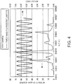
- Fig. 2 shows an example of the case where interference fringes are present.
- Fig. 2 indicates, with a solid line in the wavelength space, the reflectance (reflection coefficient, calculated value) R( ⁇ ) of a lens comprising a lens substrate with a refractive index 1.67 and a hard coating layer with a refractive index of 1.50 formed thereon to a thickness of 3 ⁇ m.
- the reflectance R( ⁇ ) line waves with gentle curves.
- the reflectance intensity distribution of reflected light is influenced by the reflectance R( ⁇ ) at each wavelength, and the peak of green near 550 nm in the spectral distribution S( ⁇ ) of the light source greatly decreases, whereby the balance of light of the three band fluorescent lamp at three wavelengths (blue, green, and red) is lost.
- the color of the reflected light is different from the original color of the light source.
- the wave of reflectance R( ⁇ ) varies from side to side, and the peaks of reflected light at three wavelengths (blue, green, and red) each repeatedly increase and decrease, resulting in interference fringes having a rainbow color.
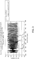
- Fig. 3 shows an example of the case where the period of reflectance R( ⁇ ) in the wavelength space is reduced, and the oscillation frequency is increased, thereby suppressing the formation of interference fringes.
- Fig. 3 indicates, with a solid line in the wavelength space, the reflectance (calculated value) R( ⁇ ) of a lens comprising a lens substrate with a refractive index 1.67 and a hard coating layer with a refractive index of 1.50 formed thereon to a thickness of 30 ⁇ m.
- the period of reflectance R( ⁇ ) is small, while the oscillation frequency is high.
- the wavelength distribution of reflection intensity of the reflected light in the case of using a three band fluorescent lamp maintains almost the same shape as that of the original relative distribution S( ⁇ ) of the light source, as indicated with a dashed line.
- the relative intensity distribution of the reflected light has almost the same shape as that of the original relative distribution S( ⁇ ) of the light source.
- the intensity distribution of the reflected light maintains the same shape as that of the original intensity distribution S( ⁇ ) of the light source.
- the spectral distribution S(k) is the spectral distribution of the above-mentioned three band fluorescent lamp F10, and the reflectance R(k) merely shows a trend.
- T ⁇ 1 ⁇ ⁇ 1 / 2 ⁇ n 1 ⁇
- n1 is the refractive index of a thin layer (hard coating layer).
- the reflectance R(k) of the functional layer laminated to the hard coating layer or a like substrate oscillates so minutely that no correlation is recognized with the spectral distribution (spectrum) S(k) of the incident light (light source)
- the correlation between the spectrum of the reflected light and the spectrum of the incident light can be increased. That is, when the period Pk of reflectance R(k) of the functional layer is made sufficiently small relative to the period of or the change in the spectral distribution (spectrum) S(k) of the incident light (light source), the correlation between the spectrum of the reflected light and the spectrum of the incident light can be increased.
- the correlation between the spectrum of the reflected light and the spectrum S(k) of the incident light is increased, it is possible to suppress the development of certain colors, whereby the formation of interference fringes can be suppressed.
- the reflectance R( ⁇ ) and specific color coordinates of the reflected light are determined, and, from the color difference in the obtained color coordinates, the presence of interference fringes is evaluated. Further, the degree of human perception of interference fringes is evaluated to define the range (upper limit) of the period Pk of reflectance R(k) of the functional layer.
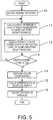
- Fig. 5 schematically shows a process of simulation regarding recognition of interference fringes.
- a model (parameters) of an optical article 5 as shown in Fig. 6 is established.
- Typical examples of parameters include the refractive index n2 of an optical substrate 2, the thickness T of a hard coating layer or like transparent functional layer 1, the refractive index n1 of a functional layer 1, the thickness nonuniformity (thickness difference) dT in the functional layer 1, and the spectral distribution S( ⁇ ) of a light source 9.
- the functional layer 1 is permeable (light-transmissive) in the visible light region. Further, the refractive index n1 of the functional layer 1 is constant, and is not changed in the thickness direction.
- wavelength distribution of a light source is the wavelength distribution of a typical fluorescent lamp specified in JIS Z 8719.
- the relative spectral distribution according to the specification of the three band fluorescent lamp F10 can be used.
- the thickness difference dT of the functional layer 1 is necessary.
- a thickness difference dT of about ⁇ 20% or 30% of the central thickness T is preferably established.
- step 11 within the range of thickness T ⁇ dT, an adequate number of sampling points having different thicknesses are established, and the reflectance at each sampling point at the wavelengths in the visible light region is calculated every appropriate wavelength. For example, in the wavelength region of 380 to 780 nm, the reflectance is calculated every 1 nm (in 1 nm increments). Sampling points are established at 50 points up and 50 points down around the thickness T, giving 101 points in total.
- step 12 the reflectance at each wavelength is calculated. Also, from the spectral distribution S( ⁇ ) of the light source (incident light) 9, color coordinates C(i) of the reflected light 8 are calculated. As the color coordinates, the coordinates in the color space of L*a*b* color system can be used, for example.
- step 13 the above operation is repeated for all the sampling points, and, within the range of thickness T ⁇ dT, the color coordinates of the 101 points C(1) to C(101) are determined.
- step 14 the average color coordinates Cav are calculated from the above-determined 101 points' color coordinates C(i).
- step 15 the color difference ⁇ E* ab (i) from the average color coordinates Cav is calculated for each color coordinates C(i) using the L*a*b* color system.
- step 16 the average dEav of the color differences ⁇ E* ab (i) was obtained as an evaluation value for evaluating the degree of interference fringes at the central thickness T.
- the average dEav is small, while the average dEav is large when many colors exist in the plane.
- the correlation table of Fig. 7 showing the correlation between color difference ⁇ E on the NBS scale and human visual sensation was employed as the primary criterion.
- the NBS scale is a standard proposed by National Bureau of Standards.
- the color difference ⁇ E on the NBS scale is not more than 1.5, the color difference is only slightly perceptible. Therefore, when the average dEav obtained from the above simulation is not more than 1.5, even in the case where interference fringes appear on the surface of the optical article 5, such interference fringes are expected to be only slightly perceptible to humans. Accordingly, such a result can be recognized as significant (category 1).
- the ranges shown in Fig. 7 are further divided to evaluate the averages dEav obtained by the simulation. Specifically, when a model (optical article) 5 has a color difference average dEav of more than 1.5, such a result does not have significance. A model (optical article) 5 having a color difference average dEav of not more than 1.5 results in interference fringes that are only slightly perceptible, and is thus preferable, and a model (optical article) 5 having a color difference average dEav of not more than 1.0 results in interference fringes with a smaller degree of slight perception, and thus is more preferable.
- a model (optical article) 5 having a color difference average dEav of not more than 0.5 results in interference fringes that are barely perceptible, and thus is preferable, and a model (optical article) 5 having a color difference average dEav of not more than 0.3 results in almost no interference fringes perceptible, and thus is more preferable.
- a model (optical article) 5 having a color difference average dEav of not more than 0.2 may result in interference fringes that are, if any, imperceptible to human eyes, and thus is most preferable.
- the reflectance is calculated every 1 nm in the visible wavelength range of 380 to 780 nm.
- Fig. 8 shows the reflectance R( ⁇ ) determined using a model 5 in which the refractive index n2 of the substrate 2 is 1.60, the refractive index n1 of the functional layer 1 is 1.50, and the thickness T of the functional layer 1 is 10 ⁇ m.
- tristimulus values (XYZ) are calculated using the formula below.
- the spectral distribution S( ⁇ ) of the light source 9 used in this case is the distribution of the three band fluorescent lamp F10 shown in Fig. 1 .
- X K ⁇ 380 780 S ⁇ ⁇ x ⁇ ⁇ ⁇ R ⁇ d ⁇
- Y K ⁇ 380 780 S ⁇ ⁇ y ⁇ ⁇ ⁇ R ⁇ d ⁇
- Z K ⁇ 380 780 S ⁇ ⁇ z ⁇ ⁇ ⁇ R ⁇ d ⁇
- K 100/ ⁇ 380 780 ( ⁇ ) ⁇ y - ( ⁇ )d ⁇ , and x - ( ⁇ ), y - ( ⁇ ), and z - ( ⁇ ) are color-matching functions in the XYZ color system.
- the CIEXYZ in the CIE color coordinates obtained from the formula (7) is (4.00, 4.13, 3.38).
- Color coordinates of the L*a*b* color system are (24.11, 0.21, 0.11).
- a thickness difference dT of ⁇ 30% of the 10- ⁇ m thickness T is established. Accordingly, at a thicknesses of 7 to 13 ⁇ m, 50 film-thickness sampling points are established on the minus side of the thickness, and another 50 film-thickness sampling points are established on the plus side of the thickness.
- the above steps 11 and 12 are repeated for each point. For example, calculations of steps 11 and 12 are performed at a thickness of 7.00 ⁇ m, calculations of steps 11 and 12 are performed at a thickness of 7.06 ⁇ m, and calculations of steps 11 and 12 are performed at a thickness of 7.12 ⁇ m. In this manner, 101 sets of color coordinates (L*, a*, b*) are obtained.
- the average (center) color is calculated. Specifically, L*, a*, and b* are each averaged. In the case of this model, the average is (23.98, 0.0, 0.0).
- the average dEav of color differences ⁇ E* of the sampling points is determined.
- the color difference average dEav was 0.40. Accordingly, interference fringes are only barely perceptible, and thus an optical article 5 showing almost no interference fringes can be provided.
- the color difference average dEav changes with a change in the parameters of the model 5.
- the average dEav is not so susceptible to the thickness nonuniformity (thickness difference) dT, and there is no large difference within the range of ⁇ 5 to 30%.
- the above-obtained coating liquid was applied onto a board 2 using a spin coater to a predetermined thickness, thereby forming a hard coating layer (functional layer) 1.
- Optical articles (spectacle lenses) 5 of Examples (E1 to E4) and Comparative Example (R1 and R2) were thus produced.
- Used as boards (substrates) 2, to which coating was applied, were Seiko Super Sovereign boards with a refractive index of 1.67 (E1, E2, and R1) and Seiko Prestige boards with a refractive index of 1.74 (E3, E4, and R2). Subsequently, the coated lens substrates were calcined at 125°C for 2 hours.
- the reflectance of each of the above-obtained spectacle lenses 5 was measured by a spectral reflectometer at wavelengths of 380 to 780 nm, and, as in the simulation, the reflected color Lab* of the light source F10 was calculated from the measured reflectance. This operation was performed at random ten measurement points from the upper part to the lower part on the board, and the average thereof was determined. The color differences ( ⁇ E) at the ten points were calculated from the average, and the average Eab of the color differences was calculated.
- Fig. 9 shows the results thereof, together with the period Pk of reflectance R(k) and the color difference average dEav obtained by simulation. As shown in the figure, the results of evaluation based on the color difference average dEav obtained by simulation are in close agreement with the results of evaluation of the products of Examples E1 to E4 and Comparative Examples R1 and R2.
- Examples E1 and E2 and Example E3 and E4 are compared with Comparative Example R1 and Comparative Example R2, respectively, in which the difference dn between the refractive index n1 of the hard coating layer 1 and the refractive index n2 of the substrate 2 is the same.
- the lenses 5 of Examples E1 and E2 in which the thickness of the hard coating layer 1 is larger and the period Pk of reflectance R(k) is shorter exhibit no or imperceptible interference fringes.
- the lenses 5 of Examples E3 and E4 having a refractive index difference dn as large as 0.19 also exhibit no or imperceptible interference fringes, because of the shortened period Pk of reflectance R(k) of the hard coating layer 1.
- the models were selected so that the refractive index n2 of the substrate 2 was within the range of 1.50 to 1.90, the refractive index n1 of the functional layer 1 was within the range of 1.50 to 1.90, and the refractive index difference at the boundary of the substrate 2 and the functional layer 1 was 0.06 to 0.40.
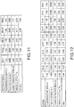
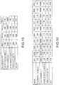
- Fig. 10 shows, among such models, models D1 to D10 that at least satisfy the above category 1, i.e., models having period Pk that gives a color difference average dEav of not more than 1.5.
- Fig. 11 shows reference models RD1 to RD5 having period Pk that gives a color difference average dEav of not less than 1.5.
- the models D1 to D10 all satisfy the requirements of the category 1 that the period Pk be not more than 3.66 ⁇ 10 -5 nm -1 and that the color difference average dEav be not more than 1.5.
- the maximum period Pk1 of reflectance R(k) of the functional layer 1 for at least satisfying the category 1 can be set at 3.66 ⁇ 10 -5 nm -1 .
- Fig. 12 shows models D11 to D20 that at least satisfy the above category 2, i.e., models having period Pk that gives a color difference average dEav of not more than 1.0.
- Fig. 13 shows reference models RD11 to RD14 having period Pk that gives a color difference average dEav of not less than 1.0.
- the models D11 to D20 all satisfy the requirements of the category 2 that the period Pk be not more than 3.03 ⁇ 10 -5 nm -1 and that the color difference average dEav be not more than 1.0.
- the maximum period Pk2 of reflectance R(k) of the functional layer 1 for at least satisfying the category 2 can be set at 3.03 ⁇ 10 -5 nm -1 .
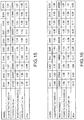
- Fig. 14 shows models D21 to D30 that at least satisfy the above category 3, i.e., models having period Pk that gives a color difference average dEav of not more than 0.5.
- the models D21 to D30 all satisfy the requirements of the category 3 that the period Pk be not more than 2.08 ⁇ 10 -5 nm -1 and that the color difference average dEav be not more than 0.5.
- the maximum period Pk3 of reflectance R(k) of the functional layer 1 for at least satisfying the category 3 can be set at 2.08 ⁇ 10 -5 nm -1 .
- Fig. 15 shows models D31 to D40 that at least satisfy the above category 4, i.e., models having period Pk that gives a color difference average dEav of not more than 0.3.
- the models D31 to D40 all satisfy the requirements of the category 4 that the period Pk be not more than 1.59 ⁇ 10 -5 nm -1 and that the color difference average dEav be not more than 0.3.
- the maximum period Pk4 of reflectance R(k) of the functional layer 1 for at least satisfying the category 4 can be set at 1.59 ⁇ 10 -5 nm -1 .
- Fig. 16 shows models D41 to D50 that at least satisfy the above category 5, i.e., models having period Pk that gives a color difference average dEav of not more than 0.2.
- the models D41 to D50 all satisfy the requirements of the category 5 that the period Pk be not more than 1.39 ⁇ 10 -5 nm -1 and that the color difference average dEav be not more than 0.2.
- the maximum period Pk5 of reflectance R(k) of the functional layer 1 for at least satisfying the category 5 can be set at 1.39 ⁇ 10 -5 nm -1 .
- the thickness T of the functional layer 1 is preferably not more than 100 ⁇ m, where cracks are less likely to occur due to drying of a formed film. When the thickness is in such a range, the surface accuracy can be easily secured.
- the period Pk of reflectance R(k) at a thickness T of 100 ⁇ m is 2.63 ⁇ 10 -6 . Such a period Pk can be adopted as the minimum period.
- the thickness T of the functional layer 1 is not more than 50 ⁇ m, the surface accuracy can be secured more easily.
- the period Pk of reflectance R(k) at a thickness T of 50 ⁇ m is 5.26 ⁇ 10 -6 .
- Such a period Pk can be adopted as the minimum period.
- the color difference due to interference fringes in only slightly perceptible. That is, in the case where the period Pk of reflectance R(k) (nm -1 ) exceeds 3.66 ⁇ 10 -5 , the color difference due to interference fringes may be appreciable, and such a case is thus undesirable.
- the wavenumber k is the reciprocal of wavelength (1/ ⁇ ).
- the color difference at least falls under the category 2. Accordingly, although color difference due to interference fringes may be slightly perceptible, the degree thereof is smaller.
- the period Pk of reflectance R(k) of the functional layer 1 is not more than 2.08 ⁇ 10 -5 , the color difference at least falls under the category 3. Accordingly, although color difference due to interference fringes may be barely perceptible, the possibility is limited.
- the period Pk of reflectance R(k) of the functional layer 1 is not more than 1.59 ⁇ 10 -5 , the color difference at least falls under the category 4. Accordingly, although color difference due to interference fringes may be barely perceptible, the degree thereof is even smaller.
- the period Pk of reflectance R(k) of the functional layer 1 is not more than 1.39 ⁇ 10 -5 , the color difference at least falls under the category 5. Accordingly, almost no color difference due to interference fringes is perceptible.
- the minimum period Pk of reflectance R(k) of the functional layer 1 is not defined.
- the period Pk is preferably not less than 2.63 ⁇ 10 -6 , and more preferably not less than 5.26 ⁇ 10 -6 .
- the period Pk of reflectance R(k) of the functional layer 1, such as a hard coating is reduced or shortened, thereby suppressing various changes in the spectrum S(k) of the light source 9, and the formation of interference fringes is thus suppressed.
- the period Pk of reflectance R(k) of the functional layer 1 is reduced far shorter than the period included in the spectrum S(k) of the light source 9 or the period that characterizes S(k)
- the spectrum of the reflected light can be matched or approximated to the spectrum of the light source 9.
- the functional layer such as a hard coating layer, which is a film with the above reflectance and having a constant refractive index that does not change in the thickness direction
- an optical substrate such as a lens
- the formation of interference fringes can be suppressed.
- the optical substrate such as a lens substrate
- a hard coating layer is described as an example of the functional layer 1.
- the structure of the hard coating layer is not limited thereto.
- resins for forming the hard coating layer include acryl-based resin, melamine-based resin, urethane-based resin, epoxy-based resin, polyvinyl-acetal-based resin, amino-based resin, polyester-based resin, polyamide-based resin, vinyl-alcohol-based resin, styrene-based resin, silicon-based resin, and mixtures or copolymers thereof.
- the resin for forming the functional layer included in the invention is not limited insofar as a transparent coating can be formed, and may be any of general-purpose resins used as coating agents.
- the functional layer 1 mainly functions as a protective film
- silicon-based resin, acryl-based resin, and urethane-based resin are preferably used for the hard coating layer
- urethane-based resin and polyester-based resin are preferably used for a primer layer for imparting adhesion.
- the hard coating layer is not limited to a monolayer, and may also have a multilayer structure.
- the functional layer 1 is not limited to the hard coating layer.
- the functional layer 1 may also include at least one primer layer that is laminated between at least one hard coating layer and the optical substrate 2 and has a constant refractive index.
- the primer layer laminated on the substrate may have a constant refractive index.
- the primer layer serves to secure the adhesion between the lens substrate 2 and the hard coating layer and/or improves the shock resistance that has been a defect of a high-refractive-index lens substrate.
- resins for forming the primer layer include acryl-based resin, melamine-based resin, urethane-based resin, epoxy-based resin, polyvinyl-acetal-based resin, amino-based resin, polyester-based resin, polyamide-based resin, vinyl-alcohol-based resin, styrene-based resin, silicon-based resin, and mixtures or copolymers thereof.
- urethane-based resin and polyester-based resin are preferably used for the primer layer for imparting adhesion.
- the refractive index of the lens substrate is n2
- the refractive index of the primer layer is n3
- the refractive index of the hard coating layer is n1
- these refractive indexes preferably satisfy the following formula: n 2 ⁇ n 3 ⁇ n 1 or n 2 ⁇ n 3 ⁇ n 1
- interference fringes can be further suppressed.
- a functional layer containing several layers having different refractive indexes reflection may occur between the internal layers. The frequency characteristics of reflectance are thus complicated, giving a wider variety of factors for the formation of interference fringes.
- the above-disclosed thickness as the whole functional layer 1 is secured, the formation of interference fringes can be suppressed.
- the method for forming a functional layer, such as a hard coating layer, on an optical substrate, such as a plastic lens may be any of the publicly known coating methods. Spin coating is preferable to make the thickness more uniform. On the other hand, in order to apply coating to a plurality of lenses at once placing prime importance on productivity, dipping is preferable.
- an inorganic antireflection film or an organic antireflection film may also be formed on the functional layer 1.
- An antireflection layer is a thin layer that is formed on the hard coating layer if necessary.
- the antireflection layer may be formed, for example, by alternately laminating a low-refractive-index layer with a refractive index of 1.3 to 1.5 and a high-refractive-index layer with a refractive index of 1.8 to 2.3.
- the number of layers is preferably about five or seven.
- Example of inorganic substances used for layers that form the antireflection layer include SiO 2 , SiO, ZrO 2 , TiO 2 , TiO, Ti 2 O 3 , Ti 2 O 5 , Al 2 O 3 , TaO 2 , Ta 2 O 5 , NbO, Nb 2 O 3 , NbO 2 , Nb 2 O 5 , CeO 2 , MgO, Y 2 O 3 , SnO 2 , MgF 2 , and WO 3 .
- These inorganic substances are used singly, or alternatively, two or more kinds are used in mixture.
- An example of the antireflection layer is one having a SiO 2 layer as a low-refractive-index layer and a ZrO 2 layer as a high-refractive-index layer.
- Examples of methods for forming the antireflection layer include dry methods, such as vacuum deposition, ion plating, and sputtering.
- vacuum deposition it is also possible to employ ion-beam-assisted deposition, in which an ion beam is applied simultaneously during vacuum evaporation.
- the antireflection layer may also be formed using a wet method.
- the layer may be formed by applying a coating composition for forming an antireflection layer, which contains silica-based particles having an inner cavity (hereinafter sometimes referred to as "hollow silica-based particles") and an organic silicon compound, in the same manner as in the formation of the hard coating layer and the primer layer.
- the reason for using hollow silica-based particles is as follows.
- the inner cavity thereof may contain a gas or solvent having a lower refractive index than that of silica, whereby the particles have reduced refractive index as compared with silica-based particles having no cavity. As a result, excellent antireflection effects can be imparted.
- Hollow silica-based particles can be produced by a method described in JP-A-2001-233611 , but those having an average particle diameter of 1 to 150 nm and a refractive index of 1.16 to 1.39 are preferably used.
- the organic antireflection layer preferably has a thickness of 50 to 150 nm. When the thickness is larger or smaller than this range, sufficient antireflection effects may not be provided.
- a water-repellent film or a hydrophilic antifogging film may also be formed on the antireflection film.
- the antifouling layer is a layer comprising a fluorine-containing organosilicon compound and is formed on the antireflection layer for the purpose of improving the water-repellent and oil-repellent properties of the optical article surface.
- fluorine-containing organosilicon compounds include fluorine-containing silane compounds described in JP-A-2005-301208 and JP-A-2006-126782 , for example.
- a fluorine-containing silane compound is preferably dissolved in an organic solvent to a prescribed concentration and used as a water-repellent processed liquid (coating composition for forming an antifouling layer).
- the antifouling layer can be formed by applying the water-repellent processed liquid (coating composition for forming an antifouling layer) onto the antireflection layer.
- the coating method therefor may be dipping, spin coating, or the like.
- the thickness of the antifouling layer is not limited, and is preferably 0.001 to 0.5 ⁇ m, and more preferably 0.001 to 0.03 ⁇ m.
- the thickness of the antifouling layer is not limited, and is preferably 0.001 to 0.5 ⁇ m, and more preferably 0.001 to 0.03 ⁇ m.
- a spectacle lens comprising a coated plastic lens is mainly taken as an example of the optical article.
- the invention enables to provide a pair of spectacles comprising a spectacle lens made of plastic provided with a thick hard coating layer as above and a frame having mounted thereto such a spectacle lens.
- interference fringes hardly appear on the surface of the lenses. Therefore, unsightly appearance can be prevented, and reflected glare and like problems can also be suppressed. Accordingly, spectacles with high commercial value can be provided.
- the optical article is not limited to a spectacle lens.
- the invention can be also applied to an optical article whose surface is exposed to a fluorescent lamp or like light having non-white spectral distribution. Examples thereof are televisions, computer displays, windows, and like systems that include an optical article with at least one side thereof facing to the outside and are used for seeing an image through the optical article.
Landscapes
- Physics & Mathematics (AREA)
- Health & Medical Sciences (AREA)
- Ophthalmology & Optometry (AREA)
- General Physics & Mathematics (AREA)
- Optics & Photonics (AREA)
- General Health & Medical Sciences (AREA)
- Surface Treatment Of Optical Elements (AREA)
- Eyeglasses (AREA)
- Laminated Bodies (AREA)
- Optical Filters (AREA)
Claims (11)
- Brillenglas, umfassend:ein optisches Substrat (2), undeine Funktionsschicht (1), die in dem sichtbaren Wellenlängenbereich lichtdurchlässig ist und an die Oberfläche des optischen Substrats laminiert ist,wobei die Reflexionsgradperiode Pk (nm-1) der Funktionsschicht in dem k-Raum nicht mehr als 3,66 × 10⁻⁵ beträgt,wobei ein Brechungskoeffizient an der Grenze des Substrats (2) und der Funktionsschicht (1) 0,06 bis 0,40 beträgt.
- Brillenglas nach Anspruch 1, wobei die Reflexionsgradperiode Pk der Funktionsschicht nicht mehr als 3,03 × 10⁻⁵ beträgt, vorzugsweise nicht mehr als 2,08 × 10⁻⁵ beträgt, bevorzugter nicht mehr als 1,59 × 10⁻⁵ beträgt, noch bevorzugter nicht mehr als 1,39 × 10⁻⁵ beträgt.
- Brillenglas nach Anspruch 1 oder 2, wobei die Reflexionsgradperiode Pk der Funktionsschicht nicht weniger als 2,63 × 10⁻⁶ beträgt, vorzugsweise nicht weniger als 5,26 × 10⁻⁶ beträgt.
- Brillenglas nach einem der vorhergehenden Ansprüche, wobei die Funktionsschicht eine hartbeschichtete Schicht umfasst.
- Brillenglas nach Anspruch 4, wobei die Funktionsschicht eine Primerschicht umfasst, die zwischen die hartbeschichtete Schicht und das optische Substrat laminiert ist.
- Brillenglas nach einem der vorhergehenden Ansprüche, das weiter einen Antireflexionsfilm umfasst, der auf die Funktionsschicht laminiert ist.
- Brillenglas nach Anspruch 6, das weiter einen Antifouling-Film umfasst, der auf den Antireflexionsfilm laminiert ist.
- Brillenglas nach einem der vorhergehenden Ansprüche, wobei das optische Substrat ein Kunststofflinsensubstrat ist.
- Brille, umfassend:ein Brillenglas nach einem der vorhergehenden Ansprüche undeinen Rahmen, an welchem das Brillenglas montiert ist.
- System, das ein Brillenglas nach einem der Ansprüche 1 bis 8 umfasst und zum Betrachten eines Bildes durch das Brillenglas dient, wobei das Brillenglas dem Äußeren zugewandt ist.
- Verfahren zum Herstellen eines Brillenglases, umfassend:Ausbilden einer Funktionsschicht, die in dem sichtbaren Wellenlängenbereich lichtdurchlässig ist, an der Oberfläche eines optischen Substrats, wobei die Reflexionsgradperiode Pk (nm-1) der Funktionsschicht in dem k-Raum nicht mehr als 3,66 × 10⁻⁵ beträgt,wobei ein Brechungskoeffizient an der Grenze des Substrats (2) und der Funktionsschicht (1) 0,06 bis 0,40 beträgt.
Applications Claiming Priority (1)
| Application Number | Priority Date | Filing Date | Title |
|---|---|---|---|
| JP2008306048A JP5430132B2 (ja) | 2008-12-01 | 2008-12-01 | 眼鏡レンズおよび眼鏡 |
Publications (2)
| Publication Number | Publication Date |
|---|---|
| EP2192424A1 EP2192424A1 (de) | 2010-06-02 |
| EP2192424B1 true EP2192424B1 (de) | 2018-07-25 |
Family
ID=41561417
Family Applications (1)
| Application Number | Title | Priority Date | Filing Date |
|---|---|---|---|
| EP09177316.8A Active EP2192424B1 (de) | 2008-12-01 | 2009-11-27 | Optischer Artikel und Verfahren zu dessen Herstellung |
Country Status (4)
| Country | Link |
|---|---|
| US (1) | US7922325B2 (de) |
| EP (1) | EP2192424B1 (de) |
| JP (1) | JP5430132B2 (de) |
| CN (1) | CN101750640B (de) |
Families Citing this family (7)
| Publication number | Priority date | Publication date | Assignee | Title |
|---|---|---|---|---|
| DE102018002384C5 (de) * | 2018-03-22 | 2022-03-10 | Shape Engineering GmbH | Verfahren zur Herstellung eines Brillenglases |
| US11678975B2 (en) | 2019-04-05 | 2023-06-20 | Amo Groningen B.V. | Systems and methods for treating ocular disease with an intraocular lens and refractive index writing |
| US11583388B2 (en) | 2019-04-05 | 2023-02-21 | Amo Groningen B.V. | Systems and methods for spectacle independence using refractive index writing with an intraocular lens |
| US11583389B2 (en) | 2019-04-05 | 2023-02-21 | Amo Groningen B.V. | Systems and methods for correcting photic phenomenon from an intraocular lens and using refractive index writing |
| US11564839B2 (en) | 2019-04-05 | 2023-01-31 | Amo Groningen B.V. | Systems and methods for vergence matching of an intraocular lens with refractive index writing |
| US11529230B2 (en) | 2019-04-05 | 2022-12-20 | Amo Groningen B.V. | Systems and methods for correcting power of an intraocular lens using refractive index writing |
| US11944574B2 (en) | 2019-04-05 | 2024-04-02 | Amo Groningen B.V. | Systems and methods for multiple layer intraocular lens and using refractive index writing |
Citations (1)
| Publication number | Priority date | Publication date | Assignee | Title |
|---|---|---|---|---|
| EP1090968A1 (de) * | 1998-05-01 | 2001-04-11 | Hoya Corporation | Beschichtungszusammensetzung, verfahren zur herstellung und kratzfeste kunststofflinse |
Family Cites Families (14)
| Publication number | Priority date | Publication date | Assignee | Title |
|---|---|---|---|---|
| JPS51121347A (en) * | 1975-04-17 | 1976-10-23 | Hoya Corp | Method of strenghtening and maintenance of strength of eye glasses len s |
| US5054902B1 (en) * | 1975-12-29 | 1998-06-23 | William J King | Light control with color enhancement |
| FR2673633B1 (fr) * | 1991-03-06 | 1993-06-11 | Air Liquide | Revetement multicouche pour substrat polycarbonate. |
| JPH0756002A (ja) | 1993-08-09 | 1995-03-03 | Shincron:Kk | ハードコート層およびその製造方法 |
| JPH09113702A (ja) | 1995-10-24 | 1997-05-02 | Nikon Corp | 光学物品およびその製造方法 |
| JP4046921B2 (ja) | 2000-02-24 | 2008-02-13 | 触媒化成工業株式会社 | シリカ系微粒子、該微粒子分散液の製造方法、および被膜付基材 |
| JP2004045988A (ja) * | 2002-07-15 | 2004-02-12 | Fuji Photo Film Co Ltd | 干渉縞防止ハードコート処理物品 |
| AU2003268723A1 (en) * | 2002-10-02 | 2004-04-23 | Bridgestone Corporation | Optical base and antireflection film |
| JP4475016B2 (ja) * | 2003-06-30 | 2010-06-09 | 東レ株式会社 | ハードコートフィルム、反射防止フィルムおよび画像表示装置 |
| US7063762B2 (en) * | 2003-08-20 | 2006-06-20 | Endicott Interconnect Technologies, Inc. | Circuitized substrate and method of making same |
| JP2005301208A (ja) | 2004-03-17 | 2005-10-27 | Seiko Epson Corp | 防汚性光学物品の製造方法 |
| JP2006126782A (ja) | 2004-10-01 | 2006-05-18 | Seiko Epson Corp | 光学物品の防汚層処理方法 |
| JP2007087550A (ja) * | 2005-09-26 | 2007-04-05 | Matsushita Electric Ind Co Ltd | 光ディスク、および光ディスクの保護層形成用塗料 |
| JP4816183B2 (ja) | 2006-03-24 | 2011-11-16 | 東レ株式会社 | 光学用積層二軸延伸ポリエステルフィルム及びそれを用いたハードコートフィルム |
-
2008
- 2008-12-01 JP JP2008306048A patent/JP5430132B2/ja active Active
-
2009
- 2009-10-21 US US12/603,421 patent/US7922325B2/en active Active
- 2009-11-27 EP EP09177316.8A patent/EP2192424B1/de active Active
- 2009-12-01 CN CN200910246698.4A patent/CN101750640B/zh active Active
Patent Citations (1)
| Publication number | Priority date | Publication date | Assignee | Title |
|---|---|---|---|---|
| EP1090968A1 (de) * | 1998-05-01 | 2001-04-11 | Hoya Corporation | Beschichtungszusammensetzung, verfahren zur herstellung und kratzfeste kunststofflinse |
Also Published As
| Publication number | Publication date |
|---|---|
| JP2010128422A (ja) | 2010-06-10 |
| EP2192424A1 (de) | 2010-06-02 |
| CN101750640B (zh) | 2014-08-06 |
| CN101750640A (zh) | 2010-06-23 |
| US20100134753A1 (en) | 2010-06-03 |
| JP5430132B2 (ja) | 2014-02-26 |
| US7922325B2 (en) | 2011-04-12 |
Similar Documents
| Publication | Publication Date | Title |
|---|---|---|
| EP2192424B1 (de) | Optischer Artikel und Verfahren zu dessen Herstellung | |
| CN103329013B (zh) | 包括在紫外区和可见光区中具有低反射的抗反射涂层的光学制品 | |
| CN105359005B (zh) | 包括在可见光区具有极低反射的抗反射涂层的光学制品 | |
| US8432624B2 (en) | Optical article and method for producing the same | |
| EP3203274B1 (de) | Ophthalmische linse mit einer dünnen antireflexbeschichtung mit sehr geringer reflexion im sichtbaren | |
| CN109791219B (zh) | 包括具有多角度效率的减反射涂层的光学镜片 | |
| CN106461965A (zh) | 包括在可见和紫外区内具有极低反射的减反射涂层的光学制品 | |
| CN107111000B (zh) | 包括在紫外区域具有高反射率的干涉涂层的光学物品 | |
| CN109716173A (zh) | 包括在近红外区(nir)中具有高反射的干涉涂层的光学制品 | |
| KR20100135837A (ko) | 저반사 유리 및 디스플레이용 보호판 | |
| CN113671604A (zh) | 包括在可见光区域内针对低照度条件的减反射涂层的光学制品 | |
| WO2011119414A1 (en) | Ion beam assisted deposition of ophthalmic lens coatings | |
| CN106896423B (zh) | 用于减反射堆叠体的复合高折射率层 | |
| CN106662671B (zh) | 包括在紫外区和可见区内均具有低反射的减反射涂层的光学制品 | |
| CN109073785A (zh) | 包括在近红外区(nir)中具有高反射的减反射涂层的光学制品 | |
| CN109642965A (zh) | 包含反射性抗磨损多层涂层的眼科镜片和用于制造所述镜片的方法 | |
| JP5464846B2 (ja) | 眼鏡レンズ、眼鏡および眼鏡レンズ製造方法 | |
| CN106341981B (zh) | 用于确定由干涉滤光片反射的比色特性的方法,用于沉积这种干涉滤光片的方法,以及由干涉滤光片和物体形成的组件 | |
| WO2021255197A1 (en) | Optical article having a multilayered antireflective coating including an encapsulated metal film | |
| CN107430211A (zh) | 具有低Rv和低Ruv的减反射溅射叠层 | |
| JP4051015B2 (ja) | 反射防止フィルム | |
| KR20190097696A (ko) | 향상된 광투과율, 정전기방지 기능 및 반사저감 기능을 가지는 코팅 조성물의 제조방법 및 이에 따라 제조된 코팅 조성물을 이용한 코팅 필름 |
Legal Events
| Date | Code | Title | Description |
|---|---|---|---|
| PUAI | Public reference made under article 153(3) epc to a published international application that has entered the european phase |
Free format text: ORIGINAL CODE: 0009012 |
|
| AK | Designated contracting states |
Kind code of ref document: A1 Designated state(s): AT BE BG CH CY CZ DE DK EE ES FI FR GB GR HR HU IE IS IT LI LT LU LV MC MK MT NL NO PL PT RO SE SI SK SM TR |
|
| AX | Request for extension of the european patent |
Extension state: AL BA RS |
|
| 17P | Request for examination filed |
Effective date: 20101202 |
|
| RAP1 | Party data changed (applicant data changed or rights of an application transferred) |
Owner name: HOYA LENS MANUFACTURING PHILIPPINES INC. |
|
| RAP1 | Party data changed (applicant data changed or rights of an application transferred) |
Owner name: EHS LENS PHILIPPINES, INC. |
|
| 17Q | First examination report despatched |
Effective date: 20160322 |
|
| REG | Reference to a national code |
Ref country code: DE Ref legal event code: R079 Ref document number: 602009053418 Country of ref document: DE Free format text: PREVIOUS MAIN CLASS: G02B0001100000 Ipc: G02B0005280000 |
|
| RIC1 | Information provided on ipc code assigned before grant |
Ipc: G02C 7/12 20060101ALI20180112BHEP Ipc: G02C 7/02 20060101ALI20180112BHEP Ipc: G02B 5/28 20060101AFI20180112BHEP Ipc: G02C 7/10 20060101ALI20180112BHEP |
|
| GRAP | Despatch of communication of intention to grant a patent |
Free format text: ORIGINAL CODE: EPIDOSNIGR1 |
|
| INTG | Intention to grant announced |
Effective date: 20180320 |
|
| GRAS | Grant fee paid |
Free format text: ORIGINAL CODE: EPIDOSNIGR3 |
|
| GRAA | (expected) grant |
Free format text: ORIGINAL CODE: 0009210 |
|
| AK | Designated contracting states |
Kind code of ref document: B1 Designated state(s): AT BE BG CH CY CZ DE DK EE ES FI FR GB GR HR HU IE IS IT LI LT LU LV MC MK MT NL NO PL PT RO SE SI SK SM TR |
|
| REG | Reference to a national code |
Ref country code: GB Ref legal event code: FG4D |
|
| REG | Reference to a national code |
Ref country code: CH Ref legal event code: EP |
|
| REG | Reference to a national code |
Ref country code: AT Ref legal event code: REF Ref document number: 1022366 Country of ref document: AT Kind code of ref document: T Effective date: 20180815 |
|
| REG | Reference to a national code |
Ref country code: DE Ref legal event code: R096 Ref document number: 602009053418 Country of ref document: DE |
|
| REG | Reference to a national code |
Ref country code: IE Ref legal event code: FG4D |
|
| REG | Reference to a national code |
Ref country code: FR Ref legal event code: PLFP Year of fee payment: 10 |
|
| REG | Reference to a national code |
Ref country code: NL Ref legal event code: MP Effective date: 20180725 |
|
| REG | Reference to a national code |
Ref country code: LT Ref legal event code: MG4D |
|
| PG25 | Lapsed in a contracting state [announced via postgrant information from national office to epo] |
Ref country code: NL Free format text: LAPSE BECAUSE OF FAILURE TO SUBMIT A TRANSLATION OF THE DESCRIPTION OR TO PAY THE FEE WITHIN THE PRESCRIBED TIME-LIMIT Effective date: 20180725 |
|
| REG | Reference to a national code |
Ref country code: AT Ref legal event code: MK05 Ref document number: 1022366 Country of ref document: AT Kind code of ref document: T Effective date: 20180725 |
|
| PG25 | Lapsed in a contracting state [announced via postgrant information from national office to epo] |
Ref country code: BG Free format text: LAPSE BECAUSE OF FAILURE TO SUBMIT A TRANSLATION OF THE DESCRIPTION OR TO PAY THE FEE WITHIN THE PRESCRIBED TIME-LIMIT Effective date: 20181025 Ref country code: GR Free format text: LAPSE BECAUSE OF FAILURE TO SUBMIT A TRANSLATION OF THE DESCRIPTION OR TO PAY THE FEE WITHIN THE PRESCRIBED TIME-LIMIT Effective date: 20181026 Ref country code: NO Free format text: LAPSE BECAUSE OF FAILURE TO SUBMIT A TRANSLATION OF THE DESCRIPTION OR TO PAY THE FEE WITHIN THE PRESCRIBED TIME-LIMIT Effective date: 20181025 Ref country code: SE Free format text: LAPSE BECAUSE OF FAILURE TO SUBMIT A TRANSLATION OF THE DESCRIPTION OR TO PAY THE FEE WITHIN THE PRESCRIBED TIME-LIMIT Effective date: 20180725 Ref country code: IS Free format text: LAPSE BECAUSE OF FAILURE TO SUBMIT A TRANSLATION OF THE DESCRIPTION OR TO PAY THE FEE WITHIN THE PRESCRIBED TIME-LIMIT Effective date: 20181125 Ref country code: AT Free format text: LAPSE BECAUSE OF FAILURE TO SUBMIT A TRANSLATION OF THE DESCRIPTION OR TO PAY THE FEE WITHIN THE PRESCRIBED TIME-LIMIT Effective date: 20180725 Ref country code: FI Free format text: LAPSE BECAUSE OF FAILURE TO SUBMIT A TRANSLATION OF THE DESCRIPTION OR TO PAY THE FEE WITHIN THE PRESCRIBED TIME-LIMIT Effective date: 20180725 Ref country code: PL Free format text: LAPSE BECAUSE OF FAILURE TO SUBMIT A TRANSLATION OF THE DESCRIPTION OR TO PAY THE FEE WITHIN THE PRESCRIBED TIME-LIMIT Effective date: 20180725 Ref country code: LT Free format text: LAPSE BECAUSE OF FAILURE TO SUBMIT A TRANSLATION OF THE DESCRIPTION OR TO PAY THE FEE WITHIN THE PRESCRIBED TIME-LIMIT Effective date: 20180725 |
|
| PG25 | Lapsed in a contracting state [announced via postgrant information from national office to epo] |
Ref country code: ES Free format text: LAPSE BECAUSE OF FAILURE TO SUBMIT A TRANSLATION OF THE DESCRIPTION OR TO PAY THE FEE WITHIN THE PRESCRIBED TIME-LIMIT Effective date: 20180725 Ref country code: HR Free format text: LAPSE BECAUSE OF FAILURE TO SUBMIT A TRANSLATION OF THE DESCRIPTION OR TO PAY THE FEE WITHIN THE PRESCRIBED TIME-LIMIT Effective date: 20180725 Ref country code: LV Free format text: LAPSE BECAUSE OF FAILURE TO SUBMIT A TRANSLATION OF THE DESCRIPTION OR TO PAY THE FEE WITHIN THE PRESCRIBED TIME-LIMIT Effective date: 20180725 |
|
| REG | Reference to a national code |
Ref country code: DE Ref legal event code: R097 Ref document number: 602009053418 Country of ref document: DE |
|
| PG25 | Lapsed in a contracting state [announced via postgrant information from national office to epo] |
Ref country code: RO Free format text: LAPSE BECAUSE OF FAILURE TO SUBMIT A TRANSLATION OF THE DESCRIPTION OR TO PAY THE FEE WITHIN THE PRESCRIBED TIME-LIMIT Effective date: 20180725 Ref country code: CZ Free format text: LAPSE BECAUSE OF FAILURE TO SUBMIT A TRANSLATION OF THE DESCRIPTION OR TO PAY THE FEE WITHIN THE PRESCRIBED TIME-LIMIT Effective date: 20180725 Ref country code: EE Free format text: LAPSE BECAUSE OF FAILURE TO SUBMIT A TRANSLATION OF THE DESCRIPTION OR TO PAY THE FEE WITHIN THE PRESCRIBED TIME-LIMIT Effective date: 20180725 Ref country code: IT Free format text: LAPSE BECAUSE OF FAILURE TO SUBMIT A TRANSLATION OF THE DESCRIPTION OR TO PAY THE FEE WITHIN THE PRESCRIBED TIME-LIMIT Effective date: 20180725 |
|
| PG25 | Lapsed in a contracting state [announced via postgrant information from national office to epo] |
Ref country code: SK Free format text: LAPSE BECAUSE OF FAILURE TO SUBMIT A TRANSLATION OF THE DESCRIPTION OR TO PAY THE FEE WITHIN THE PRESCRIBED TIME-LIMIT Effective date: 20180725 Ref country code: SM Free format text: LAPSE BECAUSE OF FAILURE TO SUBMIT A TRANSLATION OF THE DESCRIPTION OR TO PAY THE FEE WITHIN THE PRESCRIBED TIME-LIMIT Effective date: 20180725 Ref country code: DK Free format text: LAPSE BECAUSE OF FAILURE TO SUBMIT A TRANSLATION OF THE DESCRIPTION OR TO PAY THE FEE WITHIN THE PRESCRIBED TIME-LIMIT Effective date: 20180725 |
|
| PLBE | No opposition filed within time limit |
Free format text: ORIGINAL CODE: 0009261 |
|
| STAA | Information on the status of an ep patent application or granted ep patent |
Free format text: STATUS: NO OPPOSITION FILED WITHIN TIME LIMIT |
|
| REG | Reference to a national code |
Ref country code: CH Ref legal event code: PL |
|
| 26N | No opposition filed |
Effective date: 20190426 |
|
| PG25 | Lapsed in a contracting state [announced via postgrant information from national office to epo] |
Ref country code: LU Free format text: LAPSE BECAUSE OF NON-PAYMENT OF DUE FEES Effective date: 20181127 Ref country code: MC Free format text: LAPSE BECAUSE OF FAILURE TO SUBMIT A TRANSLATION OF THE DESCRIPTION OR TO PAY THE FEE WITHIN THE PRESCRIBED TIME-LIMIT Effective date: 20180725 |
|
| REG | Reference to a national code |
Ref country code: BE Ref legal event code: MM Effective date: 20181130 |
|
| REG | Reference to a national code |
Ref country code: IE Ref legal event code: MM4A |
|
| PG25 | Lapsed in a contracting state [announced via postgrant information from national office to epo] |
Ref country code: SI Free format text: LAPSE BECAUSE OF FAILURE TO SUBMIT A TRANSLATION OF THE DESCRIPTION OR TO PAY THE FEE WITHIN THE PRESCRIBED TIME-LIMIT Effective date: 20180725 Ref country code: CH Free format text: LAPSE BECAUSE OF NON-PAYMENT OF DUE FEES Effective date: 20181130 Ref country code: LI Free format text: LAPSE BECAUSE OF NON-PAYMENT OF DUE FEES Effective date: 20181130 |
|
| PG25 | Lapsed in a contracting state [announced via postgrant information from national office to epo] |
Ref country code: IE Free format text: LAPSE BECAUSE OF NON-PAYMENT OF DUE FEES Effective date: 20181127 |
|
| PG25 | Lapsed in a contracting state [announced via postgrant information from national office to epo] |
Ref country code: BE Free format text: LAPSE BECAUSE OF NON-PAYMENT OF DUE FEES Effective date: 20181130 |
|
| PG25 | Lapsed in a contracting state [announced via postgrant information from national office to epo] |
Ref country code: MT Free format text: LAPSE BECAUSE OF NON-PAYMENT OF DUE FEES Effective date: 20181127 |
|
| PG25 | Lapsed in a contracting state [announced via postgrant information from national office to epo] |
Ref country code: TR Free format text: LAPSE BECAUSE OF FAILURE TO SUBMIT A TRANSLATION OF THE DESCRIPTION OR TO PAY THE FEE WITHIN THE PRESCRIBED TIME-LIMIT Effective date: 20180725 |
|
| PG25 | Lapsed in a contracting state [announced via postgrant information from national office to epo] |
Ref country code: PT Free format text: LAPSE BECAUSE OF FAILURE TO SUBMIT A TRANSLATION OF THE DESCRIPTION OR TO PAY THE FEE WITHIN THE PRESCRIBED TIME-LIMIT Effective date: 20180725 |
|
| PG25 | Lapsed in a contracting state [announced via postgrant information from national office to epo] |
Ref country code: HU Free format text: LAPSE BECAUSE OF FAILURE TO SUBMIT A TRANSLATION OF THE DESCRIPTION OR TO PAY THE FEE WITHIN THE PRESCRIBED TIME-LIMIT; INVALID AB INITIO Effective date: 20091127 Ref country code: CY Free format text: LAPSE BECAUSE OF FAILURE TO SUBMIT A TRANSLATION OF THE DESCRIPTION OR TO PAY THE FEE WITHIN THE PRESCRIBED TIME-LIMIT Effective date: 20180725 Ref country code: MK Free format text: LAPSE BECAUSE OF NON-PAYMENT OF DUE FEES Effective date: 20180725 |
|
| P01 | Opt-out of the competence of the unified patent court (upc) registered |
Effective date: 20230418 |
|
| PGFP | Annual fee paid to national office [announced via postgrant information from national office to epo] |
Ref country code: FR Payment date: 20230929 Year of fee payment: 15 |
|
| PGFP | Annual fee paid to national office [announced via postgrant information from national office to epo] |
Ref country code: GB Payment date: 20231006 Year of fee payment: 15 |
|
| PGFP | Annual fee paid to national office [announced via postgrant information from national office to epo] |
Ref country code: DE Payment date: 20230929 Year of fee payment: 15 |