EP2190610B1 - EINRICHTUNG ZUR ÜBERLEITUNG VON STRANGGIEßBRAMMEN - Google Patents
EINRICHTUNG ZUR ÜBERLEITUNG VON STRANGGIEßBRAMMEN Download PDFInfo
- Publication number
- EP2190610B1 EP2190610B1 EP08801136.6A EP08801136A EP2190610B1 EP 2190610 B1 EP2190610 B1 EP 2190610B1 EP 08801136 A EP08801136 A EP 08801136A EP 2190610 B1 EP2190610 B1 EP 2190610B1
- Authority
- EP
- European Patent Office
- Prior art keywords
- continuous casting
- ferry
- slab
- casting strands
- casting
- Prior art date
- Legal status (The legal status is an assumption and is not a legal conclusion. Google has not performed a legal analysis and makes no representation as to the accuracy of the status listed.)
- Active
Links
Images

Classifications
-
- B—PERFORMING OPERATIONS; TRANSPORTING
- B22—CASTING; POWDER METALLURGY
- B22D—CASTING OF METALS; CASTING OF OTHER SUBSTANCES BY THE SAME PROCESSES OR DEVICES
- B22D11/00—Continuous casting of metals, i.e. casting in indefinite lengths
- B22D11/14—Plants for continuous casting
- B22D11/147—Multi-strand plants
-
- B—PERFORMING OPERATIONS; TRANSPORTING
- B22—CASTING; POWDER METALLURGY
- B22D—CASTING OF METALS; CASTING OF OTHER SUBSTANCES BY THE SAME PROCESSES OR DEVICES
- B22D11/00—Continuous casting of metals, i.e. casting in indefinite lengths
- B22D11/12—Accessories for subsequent treating or working cast stock in situ
- B22D11/1206—Accessories for subsequent treating or working cast stock in situ for plastic shaping of strands
-
- B—PERFORMING OPERATIONS; TRANSPORTING
- B21—MECHANICAL METAL-WORKING WITHOUT ESSENTIALLY REMOVING MATERIAL; PUNCHING METAL
- B21B—ROLLING OF METAL
- B21B39/00—Arrangements for moving, supporting, or positioning work, or controlling its movement, combined with or arranged in, or specially adapted for use in connection with, metal-rolling mills
- B21B39/004—Transverse moving
Definitions
- the invention relates to a device for the transfer of continuous casting slabs from parallel spaced equally spaced Strangg cordadern on an extension of a continuous casting arranged individual production line.
- EP 908 244 B1 describes a system in which emerging from two or more continuous casters casting strands are fed to a rolling mill, by means of a pivotable guide portion, which is aligned on the one hand to the continuous casting and on the other hand to the rolling line.
- This pivotable guide section also known as a swivel ferry, is assigned to the central continuous cast iron in a system with three continuous casting cores and can be swiveled in with the free end into the line of the two continuous casting tubes arranged laterally therefrom.
- the rolling line is generally aligned with the central strand, so that the split slabs arriving at the two lateral casting lines are picked up by the pivoting shuttle, diverted therefrom onto the central strand and then fed back into the rolling line.
- the arrangement of the swivel ferry means that the average continuous casting ladder is shorter and thus offers less storage or buffer space.
- the two-time reversal of direction in the transfer to the swivel ferry or when forwarding to the finishing mill increases the residence time in the furnace system and thus the formation of scale. Due to large scale losses, the output is reduced and it is to be expected with an influence on the quality of the product.
- the transfer of the thin slabs from the cast strands into the finishing train is carried out by two ferries acting as combined longitudinal / transverse / longitudinal transport systems, which are alternately aligned with the cast strands.
- the invention has for its object to provide a device for the transfer or forwarding of continuous casting, which operates with significantly reduced cycle times, so that the production flow of the continuous casting is better adapted to the finishing mill.
- a ferry which is transversely movable transversely between the ends of the continuous casting and the beginning of the production line and has the berths that serve to receive or deliver the slabs.
- the ferry has three berths, the two outer berths have the distance of the Strangg cordadern from each other and the third berth is provided between them. The ferry is then moved transversely by half the distance of the strand casting cores.
- the length of the moorings on the ferry should be at least the slab length.
- the berths can be equal to Holding furnace be formed.
- the middle caster is assigned to the finishing train, ie the middle caster is aligned in line with the finishing train.
- the ferry has two so-called berths whose lateral distance on the ferry corresponds to the distance of the strand casting of each other.
- the ferry is transversely movable between the end of the continuous casting lines and the beginning of the finishing line, stepwise, i.
- a mooring on the ferry is always aligned with the finishing train or production line and the second mooring with one of the lateral casting cords.
- the step-by-step procedure thus means that the ferry can be moved transversely to it by the distance of the continuous casting tubes.
- the embodiment of the invention provides a ferry with three berths, the two outer berths have a distance from each other, which corresponds to the distance of the Strangg cordadern each other.
- the ferry is also proceeding stepwise, but each by half the distance of the Strangg cordadern each other, so that is always aligned at any time one of the berths to a Strangg cordader and another mooring to the finishing line or production line.
- the ferry can consist of coupled together single ferries.
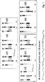
- the ferry is in front of the middle and right Strangg cordader.
- a slab has been delivered to the finishing train, while a slab has been loaded from the right-hand continuous casting ladle.
- the ferry is then moved one step to the left (1b) so that, on the one hand, a slab can be returned in the middle and, on the other, a slab is picked up on the left.
- Figure 1f shows the simultaneous loading of both berths from the middle and the right cast strand, with the simultaneous delivery of the remaining on the ferry slab in the finishing mill
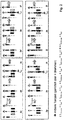
- FIG. 2 In the individual figures of the FIG. 2 is the mode of operation of a ferry shown over three Has berths, the two outer berths are spaced from each other at the distance of the strand casting and the third berth is arranged between them.
- the solution according to the invention is also suitable for pre-bands or the transfer or forwarding of other products that are to be handled in comparable production processes.
Landscapes
- Engineering & Computer Science (AREA)
- Mechanical Engineering (AREA)
- Metal Rolling (AREA)
- Continuous Casting (AREA)
- Tyre Moulding (AREA)
- Heat Treatments In General, Especially Conveying And Cooling (AREA)
- Tunnel Furnaces (AREA)
- Reciprocating Conveyors (AREA)
Description
- Die Erfindung betrifft eine Einrichtung zur Überleitung von Stranggießbrammen aus parallel im gleichen Abstand voneinander angeordneten Stranggießadern auf eine in Verlängerung einer der Stranggießadern angeordnete einzelne Produktionslinie.
- Einrichtungen dieser Art sind in verschiedensten Ausführungen bekannt.
- So ist beispielsweise in der
EP 908 244 B1 - Dieser schwenkbare Führungsabschnitt, auch Schwenkfähre genannt, ist bei einer Anlage mit drei Stranggießadern der mittleren Stranggießader zugeordnet und mit dem freien Ende in die Linie der beiden seitlich davon angeordneten Stranggießadern einschwenkbar.
- Die Walzlinie ist im allgemeinen mit der mittleren Stranggießader ausgerichtet, so dass die auf den beiden seitlichen Stranggießadern ankommenden abgeteilten Brammen von der Schwenkfähre aufgenommen, von dieser auf die mittlere Stranggießader umgelenkt und dann wieder vorwärts in die Walzlinie eingeführt werden.
- Die Bedienung von drei Stranggießadern mit einer Schwenkfähre stellt damit einen erheblichen Engpass im gesamten Produktionsfluss dar.
- Durch die große Taktzeit im Wesentlichen infolge der Zeit, die benötigt wird, um die Brammen bzw. Vorbänder aus den äußeren Strangen der Fertigstraße zuzuführen, kann das Potential dieser Fertigstraße nicht genutzt werden.
- Ist beispielsweise ein Walzenwechsel in der Fertigstraße notwendig, so muß die Zuführung auf den Stranggießadern als Puffer dienen. Wenn dieser dann abgebaut werden soll, wird bei einer großen Taktzeit eine erhebliche Zeit benötigt.
- Hinzu kommt, dass die mittlere Stranggießader durch die Anordnung der Schwenkfähre kürzer ausfällt und damit weniger Stau- oder Pufferraum bietet.
- Durch die zweimalige Richtungsumkehr bei der Überleitung auf die Schwenkfähre bzw. bei der Weiterleitung an die Fertigstraße erhöht sich die Verweildauer im Ofensystem und somit die Zunderbildung. Durch große Zunderverluste verringert sich die Ausbringung und es ist mit einem Einfluß auf die Qualität des Produktes zu rechnen.
- Weiterhin ist aus der
EP -A-0 438 066 eine Anlage zum Auswalzen von Warmbreitband aus stranggegossenen Dünnbrammen mittels einer kontinuierlichen Fertigstrasse bekannt, mit drei Gießmaschinen, von denen die mittlere in Linie zur Fertigstraße steht. Die Überführung der Dünnbrammen aus den Gusssträngen in die Fertigstraße erfolgt durch zwei als kombinierte Längs/Quer/Längs-Transportsysteme arbeitende Fähren, die wechselweise zu den Gusssträngen ausgerichtet werden. - Der Erfindung liegt die Aufgabe zugrunde, eine Einrichtung zur Überleitung oder Weiterleitung von Stranggießbrammen zu schaffen, die mit wesentlich verringerten Taktzeiten arbeitet, so dass der Produktionsfluß der Stranggießanlage besser an den der Fertigstraße anpassbar ist.
- Gelöst wird diese Aufgabe erfindungsgemäß durch eine Fähre, die stufenweise zwischen den Enden der Stranggießadern und dem Anfang der Produktionslinie quer verfahrbar ist und
die Liegeplätze aufweist, die zur Aufnahme bzw. Abgabe der Brammen dienen. Die Fähre weist drei Liegeplätze auf, wobei die beiden äußeren Liegeplätze den Abstand der Stranggießadern voneinander aufweisen und der dritte Liegeplatz zwischen diesen vorgesehen ist. Die Fähre ist dann jeweils um einen halben Abstand der Stranggießadern quer verfahrbar. - Die Länge der Liegeplätze auf der Fähre sollte mindestens der Brammenlänge entsprechen.
- Gemäß einer vorzugsweisen Ausgestaltung können die Liegeplätze gleich als Warmhalteofen ausgebildet sein.
- Die Vorteile der vorstehenden Lösungen liegen in den verringerten Taktzeiten, was klar wird, wenn man die nachfolgende Erläuterung betrachtet.
- Geht man von dem ersten nicht erfindungsgemäß Beispiel aus, so sind drei Stranggießadern vorgesehen, die im gleichen Abstand voneinander - also nebeneinander - angeordnet sind. Der mittleren Stranggießader ist die Fertigstraße zugeordnet, d. h. die mittlere Stranggießader ist in Linie mit der Fertigstraße ausgerichtet.
- Die Fähre weist zwei sogenannte Liegeplätze auf, deren seitlicher Abstand auf der Fähre dem Abstand der Stranggießadern voneinander entspricht.
- Die Fähre ist zwischen dem Ende der Stranggießadern und dem Anfang der Fertigstraße quer verfahrbar, und zwar stufenweise, d.h. beim Querverfahren ist immer ein Liegeplatz auf der Fähre mit der Fertigstraße oder Produktionslinie und der zweite Liegeplatz mit einer der seitlichen Stranggießadern ausgerichtet. Das stufenweise verfahren bedeutet somit, dass die Fähre um den Abstand der Stranggießadern voneinander quer dazu verfahrbar ist.
- Wenn vorstehend von zwei Liegeplätzen auf einer Fähre gesprochen wurde, so schließt dies natürlich auch die Möglichkeit ein, dass zwei Fähren mit jeweils einem Liegeplatz gekoppelt sind, so dass sie sich wie eine Fähre bewegungsmäßig verhalten.
- Weiter unten wird dann noch beschrieben, wie die einzelnen Bewegungsabläufe ausgeführt werden können. Die erfindungsgemäße Ausführung sieht eine Fähre mit drei Liegeplätzen vor, wobei die beiden äußeren Liegeplätze einen Abstand voneinander haben, der dem Abstand der Stranggießadern voneinander entspricht.
- Bei dieser Lösung wird dann die Fähre ebenfalls stufenweise verfahren, aber jeweils um den halben Abstand der Stranggießadern voneinander, so dass zu jedem Zeitpunkt immer einer der Liegeplätze zu einer Stranggießader und ein anderer Liegeplatz zu der Fertigstraße oder Produktionslinie ausgerichtet ist.
- Auch hierbei kann natürlich die Fähre aus miteinander gekoppelten Einzelfähren bestehen.
- Diese Lösung ist hinsichtlich der Taktzeiten optimal, was später bei Betrachtung der Bewegungsmöglichkeiten noch erläutert werden soll.
- Interessant ist bei dieser Lösung aber noch der Vorteil, dass die mittlere Stranggießader ggf. doppelt so oft angefahren werden kann, wie die beiden seitlichen Stranggießadern.
- Dies eröffnet beispielsweise die Möglichkeit, in der mittleren Stranggießader kürzere Brammenlängen zu verarbeitet oder auch die Zuführgeschwindigkeit in dieser Stranggießader höher zu wählen als in den beiden seitlichen Stranggießadern.
- Im Fall einer Pufferbildung kann mit dieser erfindungsgemäßen Lösung auch in einzelnen Stranggießadern ein unterschiedlich schneller Abbau erzielt werden.
- Zum weiteren Verständnis der Erfindung soll nun der Bewegungsablauf für die beiden Ausführungsvarianten unter Bezug auf die Zeichnungen erläutert werden, wobei in diesen die Einrichtung lediglich schematisch dargestellt ist mit drei Stranggießadern und einer Fähre.
- Geht man zunächst von der ersten nicht erfindungsgemäßen Ausführungsbeispiel aus, bei der der Abstand der Liegeplätze auf der Fähre voneinander dem Abstand der Stranggießadern voneinander entspricht, so ist im Teilbild 1a ersichtlich, dass die Fähre vor der mittleren und der rechten Stranggießader steht. In der Mitte ist eine Bramme auf die Fertigstraße abgegeben worden, während aus der rechten Stranggießader eine Bramme geladen wurde. Die Fähre wird dann um eine Stufe nach links verfahren (1b), so dass einerseits wieder in der Mitte eine Bramme abgegeben werden kann und andererseits links eine Bramme aufgenommen wird.
- Das Bild 1f zeigt das gleichzeitige Laden beider Liegeplätze aus der mittleren und der rechten Stranggießader, bei gleichzeitiger Abgabe der noch auf der Fähre befindlichen Bramme in die Fertigstraße
Es ist klar, dass bei entsprechenden Verfahren der Fähre natürlich auch die Reihenfolge der Brammenabgabe an die Fertigstraße verändert werden kann, wenn zwar eine Aufnahme einer neuen Bramme erfolgt aber durch Überfahren der mittleren Stranggießader bzw. der Fertigstraße dann erst noch eine zweite Bramme aufgenommen und diese wiederum dann zuerst abgegeben wird. - Bei der Ausführung nach den
Figuren 1a-1h ergibt sich eine mittlere Taktzeit (gemittelt über drei Brammen) nach:
- In den Einzelfiguren der
Figur 2 ist die Arbeitsweise einer Fähre dargestellt, die über drei Liegeplätze verfügt, wobei die beiden äußeren Liegeplätze im Abstand der Stranggießadern voneinander angeordnet sind und der dritte Liegeplatz zwischen diesen angeordnet ist. - Hierbei ist dann für das Erreichen einer nächsten Wechsel-, also Aufnahme- oder Abgabeposition, nur ein Verfahrweg von einem halben Stranggießadernabstand notwendig. Dabei zeigt 2b die Aufnahmeposition für eine dritte Bramme aus der linken Stranggießader und Bild 2c die Aufnahme im linken Liegeplatz und die gleichzeitige Abgabe in die Fertigstraße aus dem rechten Liegeplatz. Weitere Wechselvorgänge sind aus den anderen Bildern deutlich ersichtlich, so dass hierauf nicht im Einzelnen eingegangen werden soll.
- Die mittlere Taktzeit (gemittelt über 4 Brammen) ergibt sich aus:

- Schließlich sei noch auf die Variante nach
Figur 3 hingewiesen, wobei der Bewegungsablauf und die einzelnen Über- bzw. Abgaben der Bramme aus den einzelnenFiguren 3a bis 3j ersichtlich sind. - Auch hierfür kann eine mittlere Taktzeit (gemittelt über 3 Brammen) angegeben werden mit:

- Es sei aber noch erwähnt, dass bei der vorausgegangenen Beschreibung immer der Begriff "Bramme" benutzt worden ist.
- Die erfindungsgemäße Lösung ist aber auch für Vorbänder geeignet oder die Übergabe bzw. Weiterleitung von anderen Produkten, die in vergleichbaren Produktionprozessen zu handhaben sind.
Claims (3)
- Einrichtung zur Überleitung von Stranggießbrammen aus parallel im gleichen Abstand voneinander angeordneten Stranggießadern auf eine in Verlängerung einer der Stranggießadern angeordnete einzelne Produktionslinie,
gekennzeichnet durch
eine Fähre, die stufenweise zwischen den Enden der Stranggießadern und dem Anfang der Produktionslinie quer verfahrbar ist, die drei Liegeplätze aufweist, wobei die beiden äußeren Liegeplätze den Abstand der Stranggießadern voneinander aufweisen und der dritte Liegeplatz zwischen diesen liegt und die jeweils um einen halben Abstand der Stranggießadern quer verfahrbar ist. - Einrichtung nach Anspruch 1,
dadurch gekennzeichnet,
dass die Länge der Liegeplätze auf der Fähre mindestens der Brammenlänge entspricht. - Einrichtung nach einem der vorstehenden Ansprüche,
dadurch gekennzeichnet,
dass die Liegeplätze als Warmhalteofen ausgebildet sind.
Applications Claiming Priority (2)
| Application Number | Priority Date | Filing Date | Title |
|---|---|---|---|
| DE102007043003A DE102007043003A1 (de) | 2007-09-06 | 2007-09-06 | Einrichtung zur Überleitung von Stranggießbrammen |
| PCT/DE2008/001303 WO2009030190A1 (de) | 2007-09-06 | 2008-08-06 | EINRICHTUNG ZUR ÜBERLEITUNG VON STRANGGIEßBRAMMEN |
Publications (2)
| Publication Number | Publication Date |
|---|---|
| EP2190610A1 EP2190610A1 (de) | 2010-06-02 |
| EP2190610B1 true EP2190610B1 (de) | 2017-06-28 |
Family
ID=39865729
Family Applications (1)
| Application Number | Title | Priority Date | Filing Date |
|---|---|---|---|
| EP08801136.6A Active EP2190610B1 (de) | 2007-09-06 | 2008-08-06 | EINRICHTUNG ZUR ÜBERLEITUNG VON STRANGGIEßBRAMMEN |
Country Status (17)
| Country | Link |
|---|---|
| US (1) | US8205660B2 (de) |
| EP (1) | EP2190610B1 (de) |
| JP (1) | JP5033917B2 (de) |
| KR (1) | KR101193003B1 (de) |
| CN (1) | CN101795793B (de) |
| AR (1) | AR068209A1 (de) |
| AU (1) | AU2008295256B2 (de) |
| BR (1) | BRPI0816287A2 (de) |
| CA (1) | CA2698411A1 (de) |
| DE (1) | DE102007043003A1 (de) |
| EG (1) | EG25632A (de) |
| MX (1) | MX2010002388A (de) |
| RU (1) | RU2447970C2 (de) |
| TW (1) | TWI380860B (de) |
| UA (1) | UA95558C2 (de) |
| WO (1) | WO2009030190A1 (de) |
| ZA (1) | ZA201000365B (de) |
Families Citing this family (4)
| Publication number | Priority date | Publication date | Assignee | Title |
|---|---|---|---|---|
| DE102010008292B4 (de) | 2010-02-17 | 2024-03-07 | Sms Group Gmbh | Transportvorrichtung für Brammen |
| DE102011003146A1 (de) | 2011-01-26 | 2012-07-26 | Sms Siemag Ag | Transportsystem sowie Verfahren zum Transportieren von Walzgut zwischen mindestens zwie Verarbeitungslinien |
| CN103625880B (zh) * | 2012-08-24 | 2015-12-02 | 宝山钢铁股份有限公司 | 一种叠加式物流输送系统的控制方法 |
| EP2944386A1 (de) | 2014-05-13 | 2015-11-18 | Primetals Technologies Austria GmbH | Vorrichtung und Verfahren zur Herstellung von langen Metallprodukten |
Family Cites Families (11)
| Publication number | Priority date | Publication date | Assignee | Title |
|---|---|---|---|---|
| JPS5038394B2 (de) * | 1972-05-17 | 1975-12-09 | ||
| DE3927189A1 (de) * | 1989-08-17 | 1991-02-21 | Schloemann Siemag Ag | Anlage zur herstellung von stahlband |
| RU2044581C1 (ru) * | 1989-12-14 | 1995-09-27 | Всесоюзный научно-исследовательский и проектно-конструкторский институт металлургического машиностроения | Литейно-прокатный комплекс |
| DE4001288A1 (de) | 1990-01-18 | 1991-07-25 | Schloemann Siemag Ag | Anlage zum auswalzen von warmbreitband |
| DE4234454A1 (de) * | 1992-10-13 | 1994-04-14 | Schloemann Siemag Ag | Verfahren und Anlage zur Herstellung von warmgewalzten Bändern oder Profilen aus stranggegossenem Vormaterial |
| JPH09271840A (ja) * | 1996-04-09 | 1997-10-21 | Aida Eng Ltd | コイル材搬送装置 |
| AT407347B (de) | 1997-10-10 | 2001-02-26 | Voest Alpine Ind Anlagen | Anlage zum herstellen eines warmgewalzten produktes |
| JP2002020073A (ja) * | 2000-07-06 | 2002-01-23 | Ishikawajima Harima Heavy Ind Co Ltd | ホイストレール分岐切替機構 |
| DE10047044A1 (de) | 2000-09-22 | 2002-04-25 | Sms Demag Ag | Verfahren und Anlagen zum Herstellen von Bändern und Blechen aus Stahl |
| DE10154138A1 (de) * | 2001-11-03 | 2003-05-15 | Sms Demag Ag | Verfahren und Gießwalzanlage zum Herstellen von Stahlband, insbesondere von Edelstahl-Band |
| DE102005011254B4 (de) | 2005-03-11 | 2007-01-11 | Ispat Industries Ltd., Taluka-Pen | Verfahren und Gieß-Walz-Anlage zum Erzeugen von Warmband aus Stahlwerkstoffen |
-
2007
- 2007-09-06 DE DE102007043003A patent/DE102007043003A1/de not_active Withdrawn
-
2008
- 2008-08-06 CN CN200880105958XA patent/CN101795793B/zh not_active Expired - Fee Related
- 2008-08-06 JP JP2010523265A patent/JP5033917B2/ja not_active Expired - Fee Related
- 2008-08-06 MX MX2010002388A patent/MX2010002388A/es active IP Right Grant
- 2008-08-06 AU AU2008295256A patent/AU2008295256B2/en not_active Ceased
- 2008-08-06 KR KR1020107004834A patent/KR101193003B1/ko not_active Expired - Fee Related
- 2008-08-06 CA CA2698411A patent/CA2698411A1/en not_active Abandoned
- 2008-08-06 US US12/677,037 patent/US8205660B2/en active Active
- 2008-08-06 EP EP08801136.6A patent/EP2190610B1/de active Active
- 2008-08-06 RU RU2010112701/02A patent/RU2447970C2/ru not_active IP Right Cessation
- 2008-08-06 WO PCT/DE2008/001303 patent/WO2009030190A1/de not_active Ceased
- 2008-08-06 UA UAA201003843A patent/UA95558C2/ru unknown
- 2008-08-06 BR BRPI0816287-5A2A patent/BRPI0816287A2/pt not_active IP Right Cessation
- 2008-08-18 TW TW097131440A patent/TWI380860B/zh not_active IP Right Cessation
- 2008-09-05 AR ARP080103857A patent/AR068209A1/es unknown
-
2010
- 2010-01-18 ZA ZA201000365A patent/ZA201000365B/xx unknown
- 2010-02-09 EG EG2010020209A patent/EG25632A/xx active
Also Published As
| Publication number | Publication date |
|---|---|
| EP2190610A1 (de) | 2010-06-02 |
| UA95558C2 (ru) | 2011-08-10 |
| JP5033917B2 (ja) | 2012-09-26 |
| US8205660B2 (en) | 2012-06-26 |
| US20100200364A1 (en) | 2010-08-12 |
| AU2008295256B2 (en) | 2011-08-18 |
| EG25632A (en) | 2012-04-11 |
| KR101193003B1 (ko) | 2012-10-19 |
| RU2447970C2 (ru) | 2012-04-20 |
| AU2008295256A1 (en) | 2009-03-12 |
| CA2698411A1 (en) | 2009-03-12 |
| TWI380860B (zh) | 2013-01-01 |
| KR20100051709A (ko) | 2010-05-17 |
| MX2010002388A (es) | 2010-04-01 |
| AR068209A1 (es) | 2009-11-11 |
| CN101795793A (zh) | 2010-08-04 |
| DE102007043003A1 (de) | 2009-03-12 |
| CN101795793B (zh) | 2012-06-27 |
| JP2010537825A (ja) | 2010-12-09 |
| WO2009030190A1 (de) | 2009-03-12 |
| TW200927329A (en) | 2009-07-01 |
| ZA201000365B (en) | 2010-10-27 |
| RU2010112701A (ru) | 2011-10-20 |
| BRPI0816287A2 (pt) | 2015-03-10 |
Similar Documents
| Publication | Publication Date | Title |
|---|---|---|
| EP0593001B1 (de) | Verfahren und Anlage zur Herstellung von warmgewalzten Bändern oder Profilen aus stranggegossenem Vormaterial | |
| EP0492226A2 (de) | Verfahren und Anlage zum Auswalzen von Warmbreitband aus stranggegossenen Dünnbrammen | |
| EP1439919A1 (de) | Verfahren und giesswalzanlage zum herstellung von stahlband | |
| WO2004004938A1 (de) | Verfahren und giesswalzanlage zum semi-endloswalzen oder endloswalzen durch giessen eines metalls insbesondere eines stahlstrangs, der nach dem erstarren bei bedarf quergeteilt wird | |
| DE4234455A1 (de) | Verfahren und Anlage zum Auswalzen von Warmbreitband aus stranggegossenen Dünnbrammen | |
| WO2009030190A1 (de) | EINRICHTUNG ZUR ÜBERLEITUNG VON STRANGGIEßBRAMMEN | |
| DE1815049B1 (de) | Vorrichtung zum Ein- und Ausbringen eines Anfahrstranges einer Stranggiessanlage | |
| EP0908244B1 (de) | Anlage zum Herstellen eines warmgewalzten Produktes | |
| DE69004558T2 (de) | Vorrichtung zum Walzen und Längsteilen ohne Verwindung und Verfahren zur Herstellung von Bewehrungsstäben. | |
| AT407348B (de) | Verfahren zum herstellen eines warmgewalzten produktes und anlage zur durchführung des verfahrens | |
| DE3141618C2 (de) | Walzgerüstwechselvorrichtung für Walzstraßen | |
| EP2984009B1 (de) | Anlage zum zeitlich begrenzten aufbewahren von gegenständen | |
| EP0855456A2 (de) | Verfahren und Vorrichtung zum Transportieren voller Vorgarnspulen bzw. leerer Vorgarnhülsen | |
| DE102010008292A1 (de) | Transportvorrichtung für Brammen | |
| DE3309171A1 (de) | Wasserkuehlstrecke fuer walzwarmes walzgut | |
| DE4333775B4 (de) | Verfahren zum Austausch von Spinnbandbehältern, Einrichtung zur Durchführung des Verfahrens und Spinnbandbehälter | |
| DE1941186B2 (de) | Rollenwechsler für Rollenrichtmaschinen | |
| DE2908409A1 (de) | Walzstrasse zum walzen von staeben oder draht | |
| EP1038600A2 (de) | Anordnung des mehrgerüstigen Fertigblocks und des, diesem nachgeordneten mehrgerüstigen Nachblocks in einadrigen Drahtwalzstrassen | |
| EP0419447A1 (de) | Verfahren und Anlage zum Entzundern von Rundstahlstäben | |
| DE3029990A1 (de) | Stranggiess-walzengeruest fuer mehrstranggiessanlagen zum giessen von metall, insbesondere von stahl | |
| DE10117096B4 (de) | Vorrichtung zum Entdrallen von Walzgut-Knüppeln | |
| EP0626219B1 (de) | Entleervorrichtung für ein Rollenkühlbett | |
| DE102006023503B3 (de) | Anfahrstrang für eine Stranggießanlage | |
| DE1815049C (de) | Vorrichtung zum Ein und Ausbringen eines Anfahrstranges einer Stranggießanla ge |
Legal Events
| Date | Code | Title | Description |
|---|---|---|---|
| PUAI | Public reference made under article 153(3) epc to a published international application that has entered the european phase |
Free format text: ORIGINAL CODE: 0009012 |
|
| 17P | Request for examination filed |
Effective date: 20100406 |
|
| AK | Designated contracting states |
Kind code of ref document: A1 Designated state(s): AT BE BG CH CY CZ DE DK EE ES FI FR GB GR HR HU IE IS IT LI LT LU LV MC MT NL NO PL PT RO SE SI SK TR |
|
| AX | Request for extension of the european patent |
Extension state: AL BA MK RS |
|
| DAX | Request for extension of the european patent (deleted) | ||
| RAP1 | Party data changed (applicant data changed or rights of an application transferred) |
Owner name: SMS GROUP GMBH |
|
| GRAP | Despatch of communication of intention to grant a patent |
Free format text: ORIGINAL CODE: EPIDOSNIGR1 |
|
| INTG | Intention to grant announced |
Effective date: 20170117 |
|
| GRAS | Grant fee paid |
Free format text: ORIGINAL CODE: EPIDOSNIGR3 |
|
| GRAA | (expected) grant |
Free format text: ORIGINAL CODE: 0009210 |
|
| AK | Designated contracting states |
Kind code of ref document: B1 Designated state(s): AT BE BG CH CY CZ DE DK EE ES FI FR GB GR HR HU IE IS IT LI LT LU LV MC MT NL NO PL PT RO SE SI SK TR |
|
| REG | Reference to a national code |
Ref country code: GB Ref legal event code: FG4D Free format text: NOT ENGLISH |
|
| REG | Reference to a national code |
Ref country code: CH Ref legal event code: EP |
|
| REG | Reference to a national code |
Ref country code: AT Ref legal event code: REF Ref document number: 904406 Country of ref document: AT Kind code of ref document: T Effective date: 20170715 |
|
| REG | Reference to a national code |
Ref country code: IE Ref legal event code: FG4D Free format text: LANGUAGE OF EP DOCUMENT: GERMAN |
|
| REG | Reference to a national code |
Ref country code: DE Ref legal event code: R096 Ref document number: 502008015420 Country of ref document: DE |
|
| REG | Reference to a national code |
Ref country code: FR Ref legal event code: PLFP Year of fee payment: 10 |
|
| PG25 | Lapsed in a contracting state [announced via postgrant information from national office to epo] |
Ref country code: GR Free format text: LAPSE BECAUSE OF FAILURE TO SUBMIT A TRANSLATION OF THE DESCRIPTION OR TO PAY THE FEE WITHIN THE PRESCRIBED TIME-LIMIT Effective date: 20170929 Ref country code: NO Free format text: LAPSE BECAUSE OF FAILURE TO SUBMIT A TRANSLATION OF THE DESCRIPTION OR TO PAY THE FEE WITHIN THE PRESCRIBED TIME-LIMIT Effective date: 20170928 Ref country code: HR Free format text: LAPSE BECAUSE OF FAILURE TO SUBMIT A TRANSLATION OF THE DESCRIPTION OR TO PAY THE FEE WITHIN THE PRESCRIBED TIME-LIMIT Effective date: 20170628 Ref country code: FI Free format text: LAPSE BECAUSE OF FAILURE TO SUBMIT A TRANSLATION OF THE DESCRIPTION OR TO PAY THE FEE WITHIN THE PRESCRIBED TIME-LIMIT Effective date: 20170628 Ref country code: LT Free format text: LAPSE BECAUSE OF FAILURE TO SUBMIT A TRANSLATION OF THE DESCRIPTION OR TO PAY THE FEE WITHIN THE PRESCRIBED TIME-LIMIT Effective date: 20170628 |
|
| REG | Reference to a national code |
Ref country code: NL Ref legal event code: MP Effective date: 20170628 |
|
| REG | Reference to a national code |
Ref country code: LT Ref legal event code: MG4D |
|
| PG25 | Lapsed in a contracting state [announced via postgrant information from national office to epo] |
Ref country code: LV Free format text: LAPSE BECAUSE OF FAILURE TO SUBMIT A TRANSLATION OF THE DESCRIPTION OR TO PAY THE FEE WITHIN THE PRESCRIBED TIME-LIMIT Effective date: 20170628 Ref country code: NL Free format text: LAPSE BECAUSE OF FAILURE TO SUBMIT A TRANSLATION OF THE DESCRIPTION OR TO PAY THE FEE WITHIN THE PRESCRIBED TIME-LIMIT Effective date: 20170628 Ref country code: BG Free format text: LAPSE BECAUSE OF FAILURE TO SUBMIT A TRANSLATION OF THE DESCRIPTION OR TO PAY THE FEE WITHIN THE PRESCRIBED TIME-LIMIT Effective date: 20170928 Ref country code: SE Free format text: LAPSE BECAUSE OF FAILURE TO SUBMIT A TRANSLATION OF THE DESCRIPTION OR TO PAY THE FEE WITHIN THE PRESCRIBED TIME-LIMIT Effective date: 20170628 |
|
| PG25 | Lapsed in a contracting state [announced via postgrant information from national office to epo] |
Ref country code: RO Free format text: LAPSE BECAUSE OF FAILURE TO SUBMIT A TRANSLATION OF THE DESCRIPTION OR TO PAY THE FEE WITHIN THE PRESCRIBED TIME-LIMIT Effective date: 20170628 Ref country code: SK Free format text: LAPSE BECAUSE OF FAILURE TO SUBMIT A TRANSLATION OF THE DESCRIPTION OR TO PAY THE FEE WITHIN THE PRESCRIBED TIME-LIMIT Effective date: 20170628 Ref country code: EE Free format text: LAPSE BECAUSE OF FAILURE TO SUBMIT A TRANSLATION OF THE DESCRIPTION OR TO PAY THE FEE WITHIN THE PRESCRIBED TIME-LIMIT Effective date: 20170628 Ref country code: CZ Free format text: LAPSE BECAUSE OF FAILURE TO SUBMIT A TRANSLATION OF THE DESCRIPTION OR TO PAY THE FEE WITHIN THE PRESCRIBED TIME-LIMIT Effective date: 20170628 |
|
| PG25 | Lapsed in a contracting state [announced via postgrant information from national office to epo] |
Ref country code: IS Free format text: LAPSE BECAUSE OF FAILURE TO SUBMIT A TRANSLATION OF THE DESCRIPTION OR TO PAY THE FEE WITHIN THE PRESCRIBED TIME-LIMIT Effective date: 20171028 Ref country code: ES Free format text: LAPSE BECAUSE OF FAILURE TO SUBMIT A TRANSLATION OF THE DESCRIPTION OR TO PAY THE FEE WITHIN THE PRESCRIBED TIME-LIMIT Effective date: 20170628 Ref country code: PL Free format text: LAPSE BECAUSE OF FAILURE TO SUBMIT A TRANSLATION OF THE DESCRIPTION OR TO PAY THE FEE WITHIN THE PRESCRIBED TIME-LIMIT Effective date: 20170628 |
|
| REG | Reference to a national code |
Ref country code: CH Ref legal event code: PL Ref country code: DE Ref legal event code: R097 Ref document number: 502008015420 Country of ref document: DE |
|
| PG25 | Lapsed in a contracting state [announced via postgrant information from national office to epo] |
Ref country code: MC Free format text: LAPSE BECAUSE OF FAILURE TO SUBMIT A TRANSLATION OF THE DESCRIPTION OR TO PAY THE FEE WITHIN THE PRESCRIBED TIME-LIMIT Effective date: 20170628 |
|
| PG25 | Lapsed in a contracting state [announced via postgrant information from national office to epo] |
Ref country code: LI Free format text: LAPSE BECAUSE OF NON-PAYMENT OF DUE FEES Effective date: 20170831 Ref country code: CH Free format text: LAPSE BECAUSE OF NON-PAYMENT OF DUE FEES Effective date: 20170831 Ref country code: DK Free format text: LAPSE BECAUSE OF FAILURE TO SUBMIT A TRANSLATION OF THE DESCRIPTION OR TO PAY THE FEE WITHIN THE PRESCRIBED TIME-LIMIT Effective date: 20170628 |
|
| PLBE | No opposition filed within time limit |
Free format text: ORIGINAL CODE: 0009261 |
|
| STAA | Information on the status of an ep patent application or granted ep patent |
Free format text: STATUS: NO OPPOSITION FILED WITHIN TIME LIMIT |
|
| REG | Reference to a national code |
Ref country code: IE Ref legal event code: MM4A |
|
| 26N | No opposition filed |
Effective date: 20180329 |
|
| PG25 | Lapsed in a contracting state [announced via postgrant information from national office to epo] |
Ref country code: LU Free format text: LAPSE BECAUSE OF NON-PAYMENT OF DUE FEES Effective date: 20170806 |
|
| PG25 | Lapsed in a contracting state [announced via postgrant information from national office to epo] |
Ref country code: IE Free format text: LAPSE BECAUSE OF NON-PAYMENT OF DUE FEES Effective date: 20170806 |
|
| REG | Reference to a national code |
Ref country code: FR Ref legal event code: PLFP Year of fee payment: 11 |
|
| PG25 | Lapsed in a contracting state [announced via postgrant information from national office to epo] |
Ref country code: SI Free format text: LAPSE BECAUSE OF FAILURE TO SUBMIT A TRANSLATION OF THE DESCRIPTION OR TO PAY THE FEE WITHIN THE PRESCRIBED TIME-LIMIT Effective date: 20170628 |
|
| PG25 | Lapsed in a contracting state [announced via postgrant information from national office to epo] |
Ref country code: MT Free format text: LAPSE BECAUSE OF FAILURE TO SUBMIT A TRANSLATION OF THE DESCRIPTION OR TO PAY THE FEE WITHIN THE PRESCRIBED TIME-LIMIT Effective date: 20170628 |
|
| PG25 | Lapsed in a contracting state [announced via postgrant information from national office to epo] |
Ref country code: HU Free format text: LAPSE BECAUSE OF FAILURE TO SUBMIT A TRANSLATION OF THE DESCRIPTION OR TO PAY THE FEE WITHIN THE PRESCRIBED TIME-LIMIT; INVALID AB INITIO Effective date: 20080806 |
|
| PG25 | Lapsed in a contracting state [announced via postgrant information from national office to epo] |
Ref country code: CY Free format text: LAPSE BECAUSE OF NON-PAYMENT OF DUE FEES Effective date: 20170628 |
|
| PG25 | Lapsed in a contracting state [announced via postgrant information from national office to epo] |
Ref country code: TR Free format text: LAPSE BECAUSE OF FAILURE TO SUBMIT A TRANSLATION OF THE DESCRIPTION OR TO PAY THE FEE WITHIN THE PRESCRIBED TIME-LIMIT Effective date: 20170628 |
|
| PG25 | Lapsed in a contracting state [announced via postgrant information from national office to epo] |
Ref country code: PT Free format text: LAPSE BECAUSE OF FAILURE TO SUBMIT A TRANSLATION OF THE DESCRIPTION OR TO PAY THE FEE WITHIN THE PRESCRIBED TIME-LIMIT Effective date: 20170628 |
|
| PGFP | Annual fee paid to national office [announced via postgrant information from national office to epo] |
Ref country code: AT Payment date: 20210820 Year of fee payment: 14 |
|
| PGFP | Annual fee paid to national office [announced via postgrant information from national office to epo] |
Ref country code: BE Payment date: 20210819 Year of fee payment: 14 Ref country code: GB Payment date: 20210820 Year of fee payment: 14 |
|
| REG | Reference to a national code |
Ref country code: AT Ref legal event code: MM01 Ref document number: 904406 Country of ref document: AT Kind code of ref document: T Effective date: 20220806 |
|
| GBPC | Gb: european patent ceased through non-payment of renewal fee |
Effective date: 20220806 |
|
| PG25 | Lapsed in a contracting state [announced via postgrant information from national office to epo] |
Ref country code: AT Free format text: LAPSE BECAUSE OF NON-PAYMENT OF DUE FEES Effective date: 20220806 |
|
| REG | Reference to a national code |
Ref country code: BE Ref legal event code: MM Effective date: 20220831 |
|
| P01 | Opt-out of the competence of the unified patent court (upc) registered |
Effective date: 20230707 |
|
| PG25 | Lapsed in a contracting state [announced via postgrant information from national office to epo] |
Ref country code: BE Free format text: LAPSE BECAUSE OF NON-PAYMENT OF DUE FEES Effective date: 20220831 |
|
| PG25 | Lapsed in a contracting state [announced via postgrant information from national office to epo] |
Ref country code: GB Free format text: LAPSE BECAUSE OF NON-PAYMENT OF DUE FEES Effective date: 20220806 |
|
| PGFP | Annual fee paid to national office [announced via postgrant information from national office to epo] |
Ref country code: DE Payment date: 20240821 Year of fee payment: 17 |
|
| PGFP | Annual fee paid to national office [announced via postgrant information from national office to epo] |
Ref country code: FR Payment date: 20240828 Year of fee payment: 17 |
|
| PGFP | Annual fee paid to national office [announced via postgrant information from national office to epo] |
Ref country code: IT Payment date: 20240827 Year of fee payment: 17 |
|
| REG | Reference to a national code |
Ref country code: DE Ref legal event code: R119 Ref document number: 502008015420 Country of ref document: DE |