EP2190263B1 - Verfahren zur herstellung einer organischen dünnschicht - Google Patents
Verfahren zur herstellung einer organischen dünnschicht Download PDFInfo
- Publication number
- EP2190263B1 EP2190263B1 EP08830039A EP08830039A EP2190263B1 EP 2190263 B1 EP2190263 B1 EP 2190263B1 EP 08830039 A EP08830039 A EP 08830039A EP 08830039 A EP08830039 A EP 08830039A EP 2190263 B1 EP2190263 B1 EP 2190263B1
- Authority
- EP
- European Patent Office
- Prior art keywords
- organic material
- thin film
- evaporation
- organic
- vapor
- Prior art date
- Legal status (The legal status is an assumption and is not a legal conclusion. Google has not performed a legal analysis and makes no representation as to the accuracy of the status listed.)
- Active
Links
- 238000000034 method Methods 0.000 title claims description 8
- 239000011368 organic material Substances 0.000 claims description 151
- 238000001704 evaporation Methods 0.000 claims description 149
- 230000008020 evaporation Effects 0.000 claims description 147
- 239000010408 film Substances 0.000 claims description 80
- 239000010409 thin film Substances 0.000 claims description 70
- 239000000758 substrate Substances 0.000 claims description 62
- 238000010438 heat treatment Methods 0.000 claims description 60
- 239000012159 carrier gas Substances 0.000 claims description 55
- 238000004519 manufacturing process Methods 0.000 claims description 32
- 230000008021 deposition Effects 0.000 claims description 21
- 230000015572 biosynthetic process Effects 0.000 claims description 10
- 239000000843 powder Substances 0.000 claims description 9
- 239000000463 material Substances 0.000 claims description 8
- 239000002184 metal Substances 0.000 claims description 6
- 239000003153 chemical reaction reagent Substances 0.000 claims description 4
- 238000007599 discharging Methods 0.000 claims description 3
- 150000007530 organic bases Chemical class 0.000 claims description 2
- 239000007789 gas Substances 0.000 description 42
- 238000000151 deposition Methods 0.000 description 21
- 239000002994 raw material Substances 0.000 description 21
- 238000001816 cooling Methods 0.000 description 8
- 238000010586 diagram Methods 0.000 description 8
- 238000009826 distribution Methods 0.000 description 4
- 239000003086 colorant Substances 0.000 description 3
- 238000000354 decomposition reaction Methods 0.000 description 3
- 238000005192 partition Methods 0.000 description 3
- 239000002244 precipitate Substances 0.000 description 3
- 238000007740 vapor deposition Methods 0.000 description 3
- IJGRMHOSHXDMSA-UHFFFAOYSA-N Atomic nitrogen Chemical compound N#N IJGRMHOSHXDMSA-UHFFFAOYSA-N 0.000 description 2
- 229910001873 dinitrogen Inorganic materials 0.000 description 2
- 230000006698 induction Effects 0.000 description 2
- 238000002347 injection Methods 0.000 description 2
- 239000007924 injection Substances 0.000 description 2
- 238000001556 precipitation Methods 0.000 description 2
- 230000003213 activating effect Effects 0.000 description 1
- 230000000694 effects Effects 0.000 description 1
- 239000011521 glass Substances 0.000 description 1
- 230000005525 hole transport Effects 0.000 description 1
- 238000010030 laminating Methods 0.000 description 1
- 238000005259 measurement Methods 0.000 description 1
- 239000000203 mixture Substances 0.000 description 1
- 229910052756 noble gas Inorganic materials 0.000 description 1
- 239000011148 porous material Substances 0.000 description 1
- 230000005855 radiation Effects 0.000 description 1
Images


Classifications
-
- C—CHEMISTRY; METALLURGY
- C23—COATING METALLIC MATERIAL; COATING MATERIAL WITH METALLIC MATERIAL; CHEMICAL SURFACE TREATMENT; DIFFUSION TREATMENT OF METALLIC MATERIAL; COATING BY VACUUM EVAPORATION, BY SPUTTERING, BY ION IMPLANTATION OR BY CHEMICAL VAPOUR DEPOSITION, IN GENERAL; INHIBITING CORROSION OF METALLIC MATERIAL OR INCRUSTATION IN GENERAL
- C23C—COATING METALLIC MATERIAL; COATING MATERIAL WITH METALLIC MATERIAL; SURFACE TREATMENT OF METALLIC MATERIAL BY DIFFUSION INTO THE SURFACE, BY CHEMICAL CONVERSION OR SUBSTITUTION; COATING BY VACUUM EVAPORATION, BY SPUTTERING, BY ION IMPLANTATION OR BY CHEMICAL VAPOUR DEPOSITION, IN GENERAL
- C23C14/00—Coating by vacuum evaporation, by sputtering or by ion implantation of the coating forming material
- C23C14/22—Coating by vacuum evaporation, by sputtering or by ion implantation of the coating forming material characterised by the process of coating
- C23C14/24—Vacuum evaporation
- C23C14/246—Replenishment of source material
-
- C—CHEMISTRY; METALLURGY
- C23—COATING METALLIC MATERIAL; COATING MATERIAL WITH METALLIC MATERIAL; CHEMICAL SURFACE TREATMENT; DIFFUSION TREATMENT OF METALLIC MATERIAL; COATING BY VACUUM EVAPORATION, BY SPUTTERING, BY ION IMPLANTATION OR BY CHEMICAL VAPOUR DEPOSITION, IN GENERAL; INHIBITING CORROSION OF METALLIC MATERIAL OR INCRUSTATION IN GENERAL
- C23C—COATING METALLIC MATERIAL; COATING MATERIAL WITH METALLIC MATERIAL; SURFACE TREATMENT OF METALLIC MATERIAL BY DIFFUSION INTO THE SURFACE, BY CHEMICAL CONVERSION OR SUBSTITUTION; COATING BY VACUUM EVAPORATION, BY SPUTTERING, BY ION IMPLANTATION OR BY CHEMICAL VAPOUR DEPOSITION, IN GENERAL
- C23C14/00—Coating by vacuum evaporation, by sputtering or by ion implantation of the coating forming material
- C23C14/06—Coating by vacuum evaporation, by sputtering or by ion implantation of the coating forming material characterised by the coating material
- C23C14/12—Organic material
-
- C—CHEMISTRY; METALLURGY
- C23—COATING METALLIC MATERIAL; COATING MATERIAL WITH METALLIC MATERIAL; CHEMICAL SURFACE TREATMENT; DIFFUSION TREATMENT OF METALLIC MATERIAL; COATING BY VACUUM EVAPORATION, BY SPUTTERING, BY ION IMPLANTATION OR BY CHEMICAL VAPOUR DEPOSITION, IN GENERAL; INHIBITING CORROSION OF METALLIC MATERIAL OR INCRUSTATION IN GENERAL
- C23C—COATING METALLIC MATERIAL; COATING MATERIAL WITH METALLIC MATERIAL; SURFACE TREATMENT OF METALLIC MATERIAL BY DIFFUSION INTO THE SURFACE, BY CHEMICAL CONVERSION OR SUBSTITUTION; COATING BY VACUUM EVAPORATION, BY SPUTTERING, BY ION IMPLANTATION OR BY CHEMICAL VAPOUR DEPOSITION, IN GENERAL
- C23C14/00—Coating by vacuum evaporation, by sputtering or by ion implantation of the coating forming material
- C23C14/22—Coating by vacuum evaporation, by sputtering or by ion implantation of the coating forming material characterised by the process of coating
- C23C14/228—Gas flow assisted PVD deposition
-
- H—ELECTRICITY
- H10—SEMICONDUCTOR DEVICES; ELECTRIC SOLID-STATE DEVICES NOT OTHERWISE PROVIDED FOR
- H10K—ORGANIC ELECTRIC SOLID-STATE DEVICES
- H10K71/00—Manufacture or treatment specially adapted for the organic devices covered by this subclass
- H10K71/10—Deposition of organic active material
- H10K71/16—Deposition of organic active material using physical vapour deposition [PVD], e.g. vacuum deposition or sputtering
- H10K71/164—Deposition of organic active material using physical vapour deposition [PVD], e.g. vacuum deposition or sputtering using vacuum deposition
Definitions
- the present invention generally relates to a technique to form an organic thin film, and specifically relates to an organic material vapor generator to form an organic thin film, a film forming source having the organic material vapor generator, and a film forming apparatus having the film forming source.
- Organic EL elements are one of the most popular display elements in recent years for having excellent characteristics of high brightness and high response speed.
- light-emitting regions that produce three different colors of red, green and blue are disposed on a glass substrate.
- the light-emitting regions are configured by laminating an anode electrode film of a metal thin film, a hole injection layer, a hole transport layer, a light-emitting layer, and an electron transport layer of organic thin films, and an electron injection layer and a cathode electrode film of metal thin films in this order to produce a color of red, green, blue, or auxiliary yellow depending on a color-producing reagent added into the light-emitting layer.
- a discharger 101 of organic material vapor as illustrated in a perspective view of Fig. 7 , is used.
- the discharger 101 has vapor discharge pipes 172 in the form of a pipe.
- the vapor discharge pipes 172 are connected, by a supply pipe 127, to a production unit 105 in which organic material vapor is generated.
- organic material vapor is supplied from the production unit 105, the organic material vapor is discharged from discharge orifices 173 formed in a - large number on the vapor discharge pipes 172 in a longitudinal direction thereof towards an object to be film-formed 107, and when the vapor reaches the object to be film-formed 107; an organic thin film is formed on the surface.
- the amount of the organic material vapor discharged from the discharge orifices 173 sometimes differs in a portion near and a portion far from the position connected to the production unit 105 within the vapor discharge pipes 172. Therefore, there is a problem of poor film thickness distribution in the organic thin film formed on the surface of the object to be film-formed 107.
- the obj ect to be film-formed cannot be rotated, so that it is difficult to make the film thickness distribution uniform.
- film thickness monitors 149 F , 149 C and 149 B are disposed at positions facing a base portion (Front) near the portion connected to the supply pipe 127 of the vapor discharge pipe 172, a center portion (Center) of the vapor discharge pipe 172, and an end portion (Back) of the vapor discharge pipe 172, respectively, the end portion (Back) of the vapor discharge pipe 172 being the farthest away from the portion connected to the supply pipe 127. Only organic material vapor is introduced into the vapor discharge pipe 172 without using a carrier gas, and film thickness ratios of thin films formed at each of the positions are obtained by varying the film deposition rate.
- Table 1 The film thickness of the center portion is expressed as "1".
- Table 1 Table 1 Relationship between film deposition rate and film Film deposition ratio Film thickness ratio Back Center Front 1 ⁇ /s 0.77 1.0 1.39 7 ⁇ /s 0.88 1.0 1.08 15 ⁇ /s 0.98 1.0 1.01
- a graph of the film thickness distribution corresponding to Table 1 above is drawn at a position above the vapor discharge pipe 172 in Fig. 8 .
- L is a horizontal axis that indicates the film thickness ratio "1".
- the film deposition rate of 15 ⁇ /second is set to 7 ⁇ /second (0.7 mm/s) or less, preferably from 3 ⁇ /second (0.3 mm/s) to 5 ⁇ /second (0.5 mm/s).
- the present invention provides a technique that can form a uniform thin film even on a large-scale substrate.
- the present invention is directed to a method of manufacturing an organic thin film having the steps of disposing organic material (48) in powder form in a supply unit, connecting an evaporation chamber and a vapor discharge pipe by a supply pipe, heating an evaporation device (24) disposed in the evaporation chamber, supplying the organic material in powder form from the supply unit (to an evaporation surface of the evaporation device, evaporating the organic material supplied to the evaporation chamber by heating to generate organic metal vapor, introducing generated organic material vapor into a vapor discharge pipe by having it flow in the supply pipe, discharging it through a discharge orifice provided in the vapor discharge pipe, reaching a surface of an object to be film-formed and forming an organic thin film on the surface of the object to be film-formed, and the method of manufacturing the organic thin film in which the evaporation surface is inclined from a horizontal direction so that the organic material supplied onto the evaporation surface evaporates while sliding down on the evapor
- the present invention is also directed to the method of manufacturing an organic thin film, which is an organic thin film forming method of forming an organic thin film on one substrate by generating the organic material vapor from the organic material, and the method of manufacturing the organic thin film in which the organic material is continuously or intermittently supplied onto the evaporation surface and the organic material vapor is generated while introducing the heated carrier gas into the evaporation chamber.
- the present invention is also directed to the method of manufacturing an organic thin film, in which the temperature of the carrier gas introduced into the evaporation chamber is raised to an evaporation temperature of the organic material vapor or higher.
- the present invention is also directed to the method of manufacturing an organic thin film, in which the temperature of a porous heating filter is raised and the temperature of the carrier gas is raised by having it flow through the heating filter.
- the present invention is also directed to the method of manufacturing an organic thin film, in which the organic material is supplied from the supply unit to the evaporation device so that a film deposition rate of the organic thin film be from 3 ⁇ /second (0.3 mm/s) to 7 ⁇ /second (0.7 mm/s), and the carrier gas is introduced so that a discharge amount thereof from each of the discharge orifices disposed on the vapor discharge pipe along a longitudinal direction thereof be uniform.
- the present invention is also directed to the method of manufacturing an organic thin film, in which a pressure between the vapor discharge pipe and the surface of the object to be film-formed is from 10 -4 Pa to 10 -2 Pa.
- the present invention is also directed to the method of manufacturing an organic thin film, in which a pressure in the vapor discharge pipe during film formation is from 10 -1 Pa to 10 2 Pa.
- the present invention is also directed to the method of manufacturing an organic thin film, in which a plurality of the vapor discharge pipes is arranged on an identical plane in parallel, and the substrate and the vapor discharge pipes are relatively moved in a direction perpendicular to an extending direction of the vapor discharge pipes without changing a distance between a plane on which a surface of the substrate is positioned and a plane on which the vapor discharge pipes are positioned.
- the present invention is also directed to the method of manufacturing an organic thin film, which forms the organic
- the present invention is also directed to the method of manufacturing an organic thin film, in which a plurality of the vapor discharge pipes is arranged on an identical plane in parallel, and the substrate and the vapor discharge pipes are relatively moved in a directionperpendicular to an extending direction of the vapor discharge pipes without changing a distance between a plane on which a surface of the substrate is positioned and a plane on which the vapor discharge pipes are positioned.
- the present invention is also directed to the method of manufacturing an organic thin film, which forms the organic thin film on a plurality of the objects to be film-formed on a substrate holder by sequentially disposing the objects to be film-formed on the substrate holder, and the method of manufacturing the organic thin film in which the object to be film-formed having the organic thin film formed thereon on the substrate holder is moved while flowing the carrier gas after stopping supply of the organic material to the evaporation chamber, the unformed object to be film-formed is disposed on the substrate holder, and thereafter supply of the organic material to the evaporation chamber is restarted.
- the present invention is also directed to the method of manufacturing an organic thin film, in which an organic base material of an organic thin film emitting light in a predetermined color and an organic color-producing reagent are mixed with each other in order to form the organic material, and the organic material is evaporated in the evaporation chamber.
- the present invention is configured as described above; and when the organic material is dispersed on the inclined evaporation surface and is evaporated due to the heat transfer from the evaporation surface, the heated carrier gas is sprayed to the generated organic material vapor and the organic material vapor is carried in a state where the organic material vapor and the carrier gas are mixed. Thus, the mixed gas of the carrier gas and the organic material vapor is introduced into the vapor discharge pipe.
- the pressure of the film forming chamber during the film formation is preferably from 10 -4 Pa to 10 -2 Pa.
- the pressure of the film forming chamber is preferably set such that a mean free path becomes the interval between the discharge orifice and the substrate or more.
- the supply amount of the organic material is determined such that the film deposition rate is 7 ⁇ /second (0.7 mm/s) or less.
- the film deposition rate is from 3 ⁇ /second (0.3 mm/s) to 5 ⁇ /second (0.5 mm/s) .
- the supply amount of the carrier gas is determined such that the internal pressure of the vapor discharge pipe becomes a pressure of discharging the gas generally uniformly from the discharge orifices aligned longitudinally.
- the evaporation chamber is heated to a temperature higher than the evaporation temperature such that a portion lower than the evaporation temperature of the organic material inside the evaporation chamber does not exist; and the supply pipe and the vapor discharge pipe are also heated to a temperature higher than the evaporation temperature, so that the organic material vapor does not precipitate until the organic material vapor is discharged from the vapor discharge pipe.
- the organic material vapor generated in the evaporation chamber is carried into the discharger by the carrier gas, the residual amount of the organic material vapor within the evaporation chamber is less; and as the supply of the organic material vapor is stopped, the film formation can be immediately stopped.
- a reference numeral 1 in Fig. 1 denotes the vacuum processing apparatus having film forming apparatuses 10a to 10c.
- This vacuum processing apparatus 1 has a transfer chamber 52, to which the film forming apparatuses 10a, 10b and 10c corresponding to R, G and B, respectively, and other processing apparatuses 55 to 58 or a carry-in and out chamber 59 are connected.
- Each chamber or each of the apparatuses 10a to 10c, 52, and 55 to 59 is respectively connected to a vacuum evacuator and the inside thereof is evacuated to a vacuum atmosphere.
- a substrate transfer robot 53 is disposed inside the transfer chamber 52.
- the substrate transfer robot 53 carries in and out a substrate, as an object to be film-formed, between each chamber or each of the apparatuses 10a to 10c and 55 to 59 while maintaining the vacuum atmosphere.
- the three film forming apparatuses 10a to 10c have an identical apparatus configuration and the members in common are illustrated with the same reference numerals.
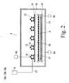
- Each of the film forming apparatuses 10a to 10c has, as illustrated in Fig. 2 and Fig. 3 , an organic material vapor generator 8 and a film forming chamber 9.
- Fig. 2 illustrates the inside of the film forming chamber 9
- Fig. 3 illustrates the inside of the organic material vapor generator 8.
- the film forming chamber 9 has a vacuum chamber 71.
- a vacuum evacuation system 83 is connected to the vacuum chamber 71, inside of which is evacuated to a vacuum atmosphere by the vacuum evacuation system 83. During the film formation, the vacuum evacuation in the film forming chamber 9 is continuously performed.
- a discharger 70 is disposed inside the vacuum chamber 71.
- This discharger 70 has a plurality of elongate vapor discharge pipes 72.
- Each vapor discharge pipe 72 is provided with a plurality of discharge orifices 73 along longitudinal directions thereof; and the inside of the vapor discharge pipe 72 is connected to an ambient atmosphere of the vapor discharge pipe 72 by the discharge orifices 73.
- each vapor discharge pipe 72 is disposed at equal intervals parallel to each other.
- each vapor discharge pipe 72 is disposed so as to be positioned on an identical plane.
- Each vapor discharge pipe 72 shares a common base portion; and a supply pipe 27 is connected to that portion.
- Each vapor discharge pipe 72 is connected to the organic material vapor generator 8 by the supply pipe 27; and as described later, organic material vapor generated in the organic material vapor generator 8 is introduced into the inside of each vapor discharge pipe 72 from the base portion thereof through the supply pipe 27.
- each vapor discharge pipe 72 is blocked and the entire amount of the gas introduced into the vapor discharge pipe 72 is discharged from each discharge orifice 73 into the vacuum chamber 71 while flowing in each vapor discharge pipe 72.
- the discharge orifices 73 are of the same size in the present embodiment, the size thereof may also be varied for flow rate adjustment. The intervals between the discharge orifices 73 may also be varied.
- a substrate holder 79 is disposed inside the vacuum chamber 71. Inside the vacuum chamber 71, a substrate holder 79 is disposed. On the substrate holder 79, a substrate 5 as an object to be film-formed is disposed.
- a mask 77 is disposed over a surface of the substrate 5, and the discharger 70 is disposed above the mask 77 interposing a cooling plate 75 therebetween.
- the substrate 5 is horizontally disposed with the surface directed vertically above, and the discharger 70 is horizontally disposed vertically above the substrate 5.
- the cooling plate 75 and the mask 77 are horizontally disposed between the discharger 70 and the substrate 5 (the cooling plate 75 being disposed between the discharger 70 and the mask 77).
- Each vapor discharge pipe 72 is provided with heaters 81 and the heaters 81 are electrified by a heating power source 82 to heat the vapor discharge pipe 72. So as not to heat the mask 77 due to the heat of the heaters 81, the cooling plate 75 is disposed between the discharger 70 and the mask 77.
- each vapor discharge pipe 72 are directed in a direction where the substrate 5 is positioned; and the discharge orifices 73 are disposed at positions in a grid pattern so as to correspond to the substrate 5 in a rectangular form.
- passage holes 76 are provided at positions of the cooling plate 75 directly facing the discharge orifices 73 and the gas discharged from the discharge orifices 73 reaches the mask 77 through the passage holes 76.
- through-holes 78 are disposed in a predetermined pattern; and of the gas that has reached the mask 77, the gas passing through the through-holes 78 reaches the substrate 5 so as to make contact with the surface of the substrate 5.
- organic material vapor is contained in the gas discharged from the discharge orifices 73; and at positions of the surface of the substrate 5 directly facing the through-holes 78, an organic thin film corresponding to the pattern of the through-holes 78 is formed.
- the vacuum chamber 71 When a gas is discharged from the vapor discharge pipes 72, the vacuum chamber 71 is continuously vacuum-evacuated from before the discharge, and residual gases that are not necessary for configuring the organic thin film are removed from the vacuum chamber 71 by the vacuum evacuation.
- the organic material vapor generator 8 has an evaporation chamber 20a that evaporates an organic material and a supply unit 40 that supplies the organic material to the evaporation chamber 20a.
- the organic material vapor generator 8 has a heating tank 31 with the inside partitioned into two sections with a partition 35, the evaporation chamber 20a being in one section, and a gas heating unit 30a being in the other section.
- the heating tank 31 is disposed outside the vacuum chamber 71, the heating tank 31 can also be disposed inside the vacuum chamber 71.
- An evaporation device 24 is disposed inside the evaporation chamber 20a.
- This evaporation device 24 is formed of a metal and an evaporation surface 28, which is a top surface of the evaporation device 24, is made smooth and inclined at an angle ⁇ relative to the horizontal direction (0 ⁇ ⁇ ⁇ 90°).
- a heating filter 32 is disposed inside the gas heating unit 30a.
- This heating filter 32 is configured with porous SiC, net-shape SiC, a laminate of metal net, or another material that is permeable to the gas and is not decomposed or does not discharge gas even when the temperature is raised to high temperatures.
- a heater 39 is disposed on side faces, a bottom face, and a surface of the heating tank 31, and is configured so as to raise the temperature of the heating tank 31 as the heater 39 is electrified by the heating power source 38 to generate heat.
- the heating filter 32 and the evaporation device 24 are heated by the heat transfer and the radiation heat from the heating tank 31.
- Induction heating coils may also be disposed outside the heating tank 31 for induction heating of the heating filter 32 and the evaporation device 24 with alternating magnetic fields.
- connection pipe 23 is disposed inside the heating tank 31 across the gas heating unit 30a and the evaporation chamber 20a.
- the partition 35 is made of a material that does not allow gas to pass therethrough; and one end of the connection pipe 23 is opened in the evaporation chamber 20a and the other end is opened in the gas heating unit 30a; thus, the gas heating unit 30a and the evaporation chamber 20a are connected to each other by the connection pipe 23 and the gas within the gas heating unit 30a can move to the evaporation chamber 20a through the connection pipe 23.
- the evaporation chamber 20a is connected to the above-described vacuum evacuation system 83, and as the evaporation chamber 20a is vacuum-evacuated, the gas within the gas heating unit 30a is also vacuum-evacuated via the connection pipe 23 and the insides of the evaporation chamber 20a and the gas heating unit 30a can be made to be at a vacuum atmosphere. During the vapor generation, however, the evaporation chamber 20a and the vacuum evacuation system 83 are blocked so as not to evacuate the generated vapor.
- a carrier gas supply system 34 is connected to the gas heating unit 30a. From the carrier gas supply system 34, a carrier gas is supplied which is composed of a noble gas, such as Ar and Xe, which does not react with the organic material. (In a case where the organic material vapor reacts with a nitrogen gas, the nitrogen gas is not suitable for the carrier gas.) As the carrier gas is supplied from the carrier gas supply system 34 to the gas heating unit 30a, the carrier gas enters the inside of the connection pipe 23 through the pores and the mesh of the heating filter 32, and flows in the connection pipe 23 and is introduced into the evaporation chamber 20a.
- a carrier gas is supplied which is composed of a noble gas, such as Ar and Xe, which does not react with the organic material. (In a case where the organic material vapor reacts with a nitrogen gas, the nitrogen gas is not suitable for the carrier gas.)
- the carrier gas As the carrier gas is supplied from the carrier gas supply system 34 to the gas heating unit 30a, the carrier gas enters the inside of the connection pipe
- the heating filter 32 is heated by the heater 39; and the carrier gas is heated to a temperature higher than the evaporation temperature of the organic material, and lower than the decomposition temperature thereof while passing through the heating filter 32.
- the supply unit 40 has a tank chamber 41 and a raw material supply pipe 42; and the tank chamber 41 is disposed above the evaporation chamber 20a.
- the raw material supplypipe 42 has an upper end air-tightly connected to a lower end of the tank chamber 41, and has a lower end air-tightly inserted inside the evaporation chamber 20a.
- the inside of the tank chamber 41 and the inside of the evaporation chamber 20a are connected to each other by the raw material supply pipe 42; and as the inside of the evaporation chamber 20a is vacuum-evacuated, the inside of the tank chamber 41 and the inside of the raw material supply pipe 42 are also vacuum-evacuated.
- the tank chamber 41 is sealed, and the atmosphere does not enter while the tank chamber 41, the raw material supply pipe 42, and the evaporation chamber 20a are vacuum-evacuated.
- a rotary shaft 46 is disposed therein with the side face having screw threads and screw grooves formed thereon.
- the raw material supply pipe 42 and the rotary shaft 46 are vertically disposed.
- the screw threads of the rotary shaft 46 and the inner wall surface of the raw material supply pipe 42 make contact with or are adjacent with a slight gap to each other; and the inside of the tank chamber 41 is connected to the evaporation chamber 20a by the screw grooves.
- the inclination angle of the screw grooves relative to the horizontal direction is small; and in a stationary state of the rotary shaft 46, even when powder smaller than the size of the screw grooves is disposed inside the tank chamber 41, it does not fall down into the evaporation chamber 20a.
- the organic material in powder form is disposed in which the base material of the organic thin film and a color-producing reagent are mixed.
- an organic material is respectively disposed such that it respectively emits light in each color of R, G and B.
- a reference numeral 48 in the diagram denotes the organic material disposed in the tank chamber 41.
- the organic material 48 in the tank chamber 41 does not move in a stationary state of the rotary shaft 46, when the rotary shaft 46 is rotated by activating a rotary driver (motor 49) connected to the rotary shaft 46, the organic material 48 enters inside the raw material supply pipe 42 through the screw grooves and moves below along the screw grooves of the raw material supply pipe 42.
- a rotary driver motor 49
- the raw material supply pipe 42 is configured such that its lower end is inserted inside the evaporation chamber 20a and connected to the connection pipe 23, and the inside of the raw material supply pipe 42 and the inside of the connection pipe 23 communicate with each other.
- the lower end of the screw grooves is opened in the raw material supply pipe 42, and the organic material having reached the lower end of the screw grooves by moving below due to the rotation of the rotary shaft 46 drops onto the inner circumference face of the connection pipe 23 from within the screw grooves.
- the rotary shaft 46 is slowly rotated, the amount of movement of the organic material within the screw grooves and the amount of rotation of the rotary shaft 46 are in one to one relationship; and if the relationship between the amount of rotation and the amount of drop is obtained in advance, it becomes possible to drop the organic material in a desired amount from the raw material supply pipe 42. When it is rotated slowly, it is possible to continuously drop the organic material by a small amount.
- connection pipe 23 is configured such that the portion between the end position in the evaporation chamber 20a and the position at which the organic material is dropped is tilted and an opening 26 at the end of the connection pipe 23 is even below the drop position. Consequently, the organic material having dropped onto the inner circumference face of the connection pipe 23 slides down towards the opening 26 on the inner circumference face of the connection pipe 23.
- the opening 26 is disposed immediately above the evaporation surface 28 of the evaporation device 24, and the organic material having reached the opening 26 drops onto the evaporation surface 28 from the opening 26.
- the organic material having dropped onto the evaporation surface 28 is dispersed on the evaporation surface 28. Since the evaporation surface 28 is tilted, the organic material slides down onto the evaporation surface 28 in a spread state.
- the organic material that drops onto the evaporation surface 28 is in powder form at room temperature, the organic material evaporates when heated to the evaporation temperature or higher, and organic material vapor is generated.
- the evaporation device 24 is raised to a temperature higher than the evaporation temperature of the organic material by the heater 39 in advance. Further, since the organic material is supplied on the evaporation surface 28 in an amount that is allowed to be completely evaporated before the organic material slides down the evaporation surface 28 and reaches the lower end thereof (that is, while sliding down), the organic material starts evaporation immediately after being dispersed on the evaporation surface 28, evaporates while sliding down, and disappears from the evaporation surface 28 without reaching the lower end thereof.
- the vacuum evacuation in the vacuum chamber 71 is performed while the valve between the evaporation chamber 20a and the vacuum evacuation system 83 is closed so as not to vacuum-evacuate the organic material vapor generated in the evaporation chamber 20a by the evaporation of the organic material without passing through the discharger 70.
- the evaporation chamber 20a and the discharger 70 are connected to each other by the supply pipe 27.
- the carrier gas is supplied to the gas heating unit 30a, prior to the dropping of the organic material so as to allow the heated carrier gas to be introduced into the evaporation chamber 20a.
- the opening 26 of the connection pipe 23 in which the heated carrier gas flows is directed to the portion of the evaporation surface 28 where the organic material evaporates and the heated carrier gas is sprayed to that portion, the organic material vapor and the heated carrier gas are uniformly mixed in the evaporation chamber 20a; and the mixed gas is introduced into the vapor discharge pipes 72 through the supply pipe 27.
- the internal pressure of the vapor discharge pipes 72 is set at a magnitude for forming a viscous flow of the mixed gas (mixed gas of the carrier gas and the organic material vapor) inside the vapor discharge pipes 72, and the inside of each vapor discharge pipe 72 is filled with the mixed gas of an approximately equal pressure from the base through the end.
- the inside of the vacuum chamber 71 is continuously vacuum-evacuated directly, and the ambient pressure of the vapor discharge pipes 72 is lower than the internal pressure of the vapor discharge pipes 72.
- the mixed gas is discharged from each discharge orifice 73 at an equal flow rate, and the organic material vapor reaches the surface of the substrate 5 at a uniform density per unit area through the passage holes 76 of the cooling plate 75 and the through-holes 78 of the mask 77.
- the pressure within the vapor discharge pipes 72 can be at a pressure possible to uniformly discharge vapor through the discharge orifices 73 between the end and the base portion.
- the organic material vapor reaches the surface of the substrate in an equal amount from the base through the end of each vapor discharge pipe 72, an organic thin film without unevenness can be obtained.
- the film forming chamber 9 is provided with a shifter 85. While the substrate holder 79, the substrate 5, and the mask 77 are relatively stationary, and the discharger 70 and the cooling plate 75 are relatively stationary, the substrate 5 and each vapor discharge pipe 72 are configured to relatively move by the shifter 85.
- the directions of movement of the shifter 85 are directions perpendicular to the extending directions of the vapor discharge pipes 72 without changing the distance between the plane where the substrate 5 is positioned and the plane where the vapor discharge pipes 72 are positioned. As the relatively reciprocating movement is repeated in such directions, a uniform organic thin film is formed on the surface of the substrate 5.
- the relative movement of the shifter 85 may also be arranged such that the substrate 5 (and the substrate holder 79 and the mask 77) is stationary relative to the vacuum chamber 71 and the discharger 70 (and the cooling plate 75) moves relative to the vacuum chamber 71. It may also be in such a way that the discharger 70 is stationary relative to the vacuum chamber 71 and the substrate 5 moves relative to the vacuum chamber 71. Both the substrate 5 and the discharger 70 may also be arranged to move.
- the directions of relative movement may also have, in addition to the component in a direction perpendicular to the extending directions of the vapor discharge pipes 72, a component parallel to that and may also be arranged to relatively move in a circle.
- the substrate 5 is moved into the next film forming apparatuses 10b and 10c sequentially by the substrate transfer robot 53 to form organic thin films corresponding to the rest of the colors respectively at predetermined positions on the substrate 5 and to be carried in other processing chambers 55 to 58, if needed, for vacuum processing, such as formation of charge transfer layers and electrode films, and then, the substrate is carried out of the vacuum processing apparatus 1.
- the heating tank 31 and the carrier gas are raised to a temperature higher than the evaporation temperature of the organic material (here, the evaporation temperature is assumed to be equal to the precipitation temperature) and the organic material vapor does not form at a temperature of the precipitation temperature or less, so that the organic material does not precipitate into the heating tank 31.
- the organic material is supplied from the supply unit 40 into the evaporation chamber 20a at a supply speed such that the organic material dropped onto the evaporation surface 28 evaporates while sliding down the evaporation surface 28; and as the drop of the organic material onto the evaporation surface 28 is stopped, the organic material in powder form on the evaporation surface 28 immediately disappears. Consequently, the generation of the organic material vapor is also stopped almost at the same time when the supply of the organic material from the supply unit 40 to the evaporation chamber 20a is stopped.
- the pressure of the heated carrier gas is arranged to be higher than the pressure of the generated organic material vapor; and as a result, a small amount of the organic material gas is carried into the discharger 70 with a large amount of the heated carrier gas flow, so that when the supply of the organic material from the supply unit 40 to the evaporation device 24 is stopped, the generation of the organic material vapor within the evaporation chamber 20a is immediately stopped. Further, the organic material vapor filling the evaporation chamber 20a immediately moves into the discharger 70 due to the heated carrier gas and is immediately discharged.
- the organic material vapor is quickly purged, so that the time until the film formation is stopped can be shortened. Also, the insides of the evaporation chamber 20a, the supply pipe 27, and the discharger 70 can be securely purged.
- Fig. 9 is a graph for showing the relationship between time and the measurements of the film thickness monitors disposed at the positions facing the vapor discharge pipe 72 when the organic material is dropped onto the evaporation device 24 at predetermined time intervals while maintaining the temperature of the evaporation device 24 at a constant temperature of about 300°C.
- each of the film forming apparatuses 10a, 10b and 10c to form an organic thin film on a plurality of substrates 5 in order, while moving the object to be film-formed having an organic thin film formed thereon from the substrate holder 79 and disposing an unformed object to be film-formed on the substrate holder 79, the supply of the organic material from the supply unit 40 to the evaporation chamber 20a is stopped. After disposing the object to be film-formed before film formation on the substrate holder 79, the supply of the organic material from the supply unit 40 to the evaporation chamber 20a is restarted to start film formation.
- the temperature of the heating filter is constantly maintained, so that the temperature of the mixed gas discharged from the discharger 70 also becomes constant and the film quality of the formed organic thin film becomes less varied.
- the inside of the heating tank 31 is partitioned with the partition 35 that does not allow a gas to pass therethrough
- the inside of the heating tank 31 may also be partitioned with an air permeable plate 37 that allows a gas to pass therethrough, as illustrated in Fig. 4 , in order to form an evaporation chamber 20b and a gas heating unit 30b.
- the carrier gas heated when passing through the heating filter 32 in the gas heating unit 30b, is introduced into the evaporation chamber 20b through the air permeable plate 37.
- connection pipe that connects the evaporation chamber 20b and the gas heating unit 30b is not necessary, and as the evaporation device 24 is disposed immediately below the raw material supply pipe 42, the organic material can be dropped from the raw material supply pipe 42 onto the evaporation surface 28 without passing through the connection pipe.
- the gas heating units 30a and 30b are disposed inside the heating tank 31, the present invention is not limited thereto. As illustrated in Fig. 5 , a gas heating unit 30c can also be disposed outside the heating tank 31. In this case, the entire inside of the heating tank 31 may also be taken as an evaporation chamber 20c and the heating tank 31 and the evaporation chamber 20c may also be connected to each other by the connection pipe 23.
- the lower end of the raw material supply pipe 42 can also be connected to the connection pipe 23 for allowing the organic material to drop from the raw material supply pipe 42, slide down in the connection pipe 23 and drop onto the evaporation surface 28.
- the carrier gas is heated higher than the evaporation temperature of the organic material, so that the evaporation chamber 20a and the supply pipe 27 are not cooled down and the organic material vapor does not precipitate therein. It is also possible to dispose a heater on the outer circumference of the supply pipe 27 so as to heat the supply pipe 27.
- the heater which heats the heating tank 31 and the supply pipe 27, heats the evaporation device 24, the supply pipe 27, and the carrier gas so as to raise the temperature lower than the decomposition temperature of the organic material, so that the organic material is not decomposed.
- the supply unit 40 has the raw material supply pipe 42, the rotary shaft 46 disposed therein, and the motor 49 for rotating the rotary shaft 46, the supply unit 40 is however not limited thereto.
- a supply unit that can supply a predetermined amount of the organic material on the evaporation surface 28 by a small amount may suffice.
- the film thickness of an organic thin film formed on the surface of one substrate 5 is generally determined in advance and almost all the organic material vapor generated in the evaporation chamber 20a is discharged from the discharger 70, it is possible to obtain the amount of the organic material such that the supply unit 40 should supply for the formation of an organic thin film of a film thickness determined in advance.
- the supply speed of the organic material that is supplied to the evaporation chamber 20a by the supply unit 40 is also determined, the rotation speed of the rotary shaft 46 is determined so as to obtain the supply speed.
- the tank chamber 41 is not heated, the supply unit 40 is cooled down, and the organic material existing in the tank chamber 41 and the supply unit 40 is maintained at temperatures of approximately room temperature.
- the organic material is supplied into the evaporation chamber 20a by a small amount, so that the organic material in the tank chamber 41 and the supply unit 40 is maintained at temperatures of approximately room temperature and it is possible to prevent decomposition due to heating.
- the carrier gas is heated by flowing the carrier gas into the porous or net-shaped heating filter at a raised temperature in the above-described embodiments, the temperature may also be raised by flowing the carrier gas into various heat exchangers.
- the film forming time period and the supply speed can be obtained from the amount of the organic material obtained from the film thickness and the defined film deposition rate, so that the rotary shaft 46 can be continuously rotated during the film forming time period at a rotation speed calculated from the obtained supply speed, and the organic material can be dropped intermittently by intermittently rotating the rotary shaft 46 in a short cycle such that the organic material is supplied in the obtained amount within the film forming time period.
Claims (10)
- Verfahren des Herstellens eines organischen Dünnfilms enthaltend die Schritte, Anordnen eines organischen Materials (48) in Puderform in einer Versorgungseinheit (40), Verbinden einer Verdampfungskammer (20a) und einer Dampfablassröhre (72) durch eine Versorgungsröhre (27), Heizen einer Verdampfungsvorrichtung (24), die in der Verdampfungskammer (20a) angeordnet ist, Zuführen des organischen Materials in Puderform von der Versorgungseinheit (40) zu einer Verdampfungsfläche (28) der Verdampfungsvorrichtung (24), Verdampfen des der Verdampfungskammer (20a) zugeführten organischen Materials (48) durch Erhitzen, um organischen Metalldampf zu erzeugen, Einlassen des erzeugten organischen Metalldampfes in eine Dampfablassröhre (72), indem er in der Versorgungsröhre (27) geströmt wird, Ablassen durch eine in der Dampfablassröhre (72) angeordnete Ablassöffnung (73), Erreichen einer Oberfläche eines Objekts, das zu filmgestalten ist, und Bilden eines organischen Dünnfilms auf der Oberfläche des Objekts, das zu filmgestalten ist, wobei das Verfahren des Herstellens des organischen Dünnfilms dadurch gekennzeichnet ist, dass die Verdampfungsfläche (28) gegen eine horizontale Richtung geneigt ist, so dass das organische Material (48), das auf die Verdampfungsfläche (28) zugeführt wird, verdampft, während es auf der Verdampfungsfläche (28) nach unten rutscht, eine Zuführgeschwindigkeit des organischen Materials (48) an die Verdampfungsfläche (28) auf eine Größe festgelegt ist, so dass das organische Material (48) auf der Verdampfungsfläche (28) verschwindet, bevor es ein unteres Ende der Verdampfungsfläche (28) erreicht, ein Trägergas in die Verdampfungskammer (20a) eingelassen wird, und das Trägergas und der organische Materialdampf in die Dampfablassröhre (72) eingelassen werden.
- Verfahren des Herstellens eines organischen Dünnfilms gemäß Anspruch 1, das ein organisches Dünnfilmbildungsverfahren des Bildens eines organischen Dünnfilms auf einem Substrat (5) durch Erzeugen des organischen Materialdampfes aus dem organischen Material (48) ist, wobei das Verfahren des Herstellens des organischen Dünnfilms dadurch gekennzeichnet ist, dass das organische Material (48) kontinuierlich oder stoßweise auf die Verdampfungsfläche (28) zugeführt wird und der organische Materialdampf erzeugt wird, während das geheizte Trägergas in die Verdampfungskammer (20a) eingelassen wird.
- Verfahren des Herstellens eines organischen Dünnfilms gemäß Anspruch 1, dadurch gekennzeichnet, dass die Temperatur des Trägergases, das in die Verdampfungskammer (20a) eingelassen wird, auf eine Verdampfungstemperatur des organischen Materialdampfes oder höher erhöht wird.
- Verfahren des Herstellens eines organischen Dünnfilms gemäß Anspruch 3, dadurch gekennzeichnet, dass die Temperatur eines porösen Heizfilters (32) erhöht wird und die Temperatur des Trägergases erhöht wird, indem es durch den Heizfilter (32) geströmt wird.
- Verfahren des Herstellens eines organischen Dünnfilms gemäß Anspruch 1, dadurch gekennzeichnet, dass das organische Material von der Versorgungseinheit (40) der Verdampfungsvorrichtung (24) zugeführt wird, so dass eine Filmaufbringungsrate des organischen Dünnfilms von 0.3 µm/s bis 7 µm/s ist, und das Trägergas so eingelassen wird, dass eine Ablassmenge davon aus jeder der Ablassöffnungen (73), die auf der Dampfablassröhre (72) entlang einer Längsrichtung davon angeordnet sind, gleich ist.
- Verfahren des Herstellens eines organischen Dünnfilms gemäß Anspruch 1, dadurch gekennzeichnet, dass ein Druck zwischen der Dampfablassröhre (72) und der Oberfläche des Objekts, das zu filmgestalten ist, von 10-4 Pa bis 10-2 Pa ist.
- Verfahren des Herstellens eines organischen Dünnfilms gemäß Anspruch 1, dadurch gekennzeichnet, dass ein Druck in der Dampfablassröhre (72) während der Filmbildung von 10-1 Pa bis 102 Pa ist.
- Verfahren des Herstellens eines organischen Dünnfilms gemäß Anspruch 1, dadurch gekennzeichnet, dass mehrere der Dampfablassröhren (72) auf einer identischen Ebene parallel angeordnet sind, und das Substrat (5) und die Dampfablassröhren (72) relativ in einer Richtung senkrecht zu einer Ausdehnungsrichtung der Dampfablassröhren (72) bewegt werden ohne eine Entfernung zwischen einer Ebene, auf der eine Oberfläche des Substrats (5) positioniert ist, und einer Ebene, auf der die Dampfablassröhren (72) positioniert sind, verändert wird.
- Verfahren des Herstellens eines organischen Dünnfilms gemäß Anspruch 1, das den organischen Dünnfilm auf mehreren der Objekte, die zu filmgestalten sind, auf einem Substrathalter (79) formt, indem die Objekte, die zu filmgestalten sind, nacheinander auf dem Substrathalter (79) angeordnet werden, wobei das Verfahren des Herstellens des organischen Dünnfilms dadurch gekennzeichnet ist, dass das Objekt auf dem Substrathalter (79), das zu filmgestalten ist, auf dem der organischen Dünnfilm geformt wird, bewegt wird, während das Trägergas geströmt wird, nachdem die Zuführung des organischen Materials (48) an die Verdampfungskammer (20a) unterbrochen wird, das ungestaltete Objekt, das zu filmgestalten ist, auf dem Substrathalter (79) angeordnet wird, und danach die Zuführung des organischen Materials (48) an die Verdampfungskammer (20a) wieder gestartet wird.
- Verfahren des Herstellens eines organischen Dünnfilms gemäß Anspruch 1, dadurch gekennzeichnet, dass ein organisches Basismaterial eines organischen Dünnfilms, der Licht in einer vorbestimmten Farbe emittiert, und ein organisches farbproduzierendes Reagenz miteinander gemischt werden, um das organische Material (48) zu bilden, und das organische Material (48) in der Verdampfungskammer (20a) verdampft wird.
Applications Claiming Priority (3)
| Application Number | Priority Date | Filing Date | Title |
|---|---|---|---|
| JP2007234441 | 2007-09-10 | ||
| JP2008043481 | 2008-02-25 | ||
| PCT/JP2008/066150 WO2009034939A1 (ja) | 2007-09-10 | 2008-09-08 | 有機薄膜製造方法 |
Publications (3)
| Publication Number | Publication Date |
|---|---|
| EP2190263A1 EP2190263A1 (de) | 2010-05-26 |
| EP2190263A4 EP2190263A4 (de) | 2011-11-09 |
| EP2190263B1 true EP2190263B1 (de) | 2013-03-20 |
Family
ID=40451947
Family Applications (1)
| Application Number | Title | Priority Date | Filing Date |
|---|---|---|---|
| EP08830039A Active EP2190263B1 (de) | 2007-09-10 | 2008-09-08 | Verfahren zur herstellung einer organischen dünnschicht |
Country Status (7)
| Country | Link |
|---|---|
| US (1) | US8420169B2 (de) |
| EP (1) | EP2190263B1 (de) |
| JP (1) | JP5374374B2 (de) |
| KR (1) | KR101128747B1 (de) |
| CN (1) | CN101803461B (de) |
| TW (1) | TWI470096B (de) |
| WO (1) | WO2009034939A1 (de) |
Families Citing this family (9)
| Publication number | Priority date | Publication date | Assignee | Title |
|---|---|---|---|---|
| JP5703166B2 (ja) * | 2011-08-04 | 2015-04-15 | 株式会社アルバック | 蒸着装置及び蒸着方法 |
| JP2013104127A (ja) * | 2011-11-16 | 2013-05-30 | Mitsubishi Heavy Ind Ltd | 真空蒸着装置 |
| JP2015129316A (ja) * | 2012-04-20 | 2015-07-16 | 東京エレクトロン株式会社 | ガスフロー蒸着装置、及びガスフロー蒸着方法 |
| DE102012220986B4 (de) * | 2012-11-16 | 2015-04-02 | Innovent E.V. Technologieentwicklung | Dosiereinheit und ihre Verwendung |
| KR102150625B1 (ko) * | 2013-03-15 | 2020-10-27 | 삼성디스플레이 주식회사 | 코팅장치 |
| KR20160123438A (ko) * | 2015-04-15 | 2016-10-26 | 삼성디스플레이 주식회사 | 유기 발광 디스플레이 장치용 증착원 |
| DE102017120529A1 (de) * | 2017-09-06 | 2019-03-07 | Aixtron Se | Vorrichtung zum Abscheiden einer strukturierten Schicht auf einem Substrat unter Verwendung einer Maske |
| CN107881485B (zh) * | 2017-11-01 | 2019-10-01 | 深圳市华星光电半导体显示技术有限公司 | 等离子体增强化学气相沉积设备及oled面板的封装方法 |
| US11842907B2 (en) | 2020-07-08 | 2023-12-12 | Applied Materials, Inc. | Spot heating by moving a beam with horizontal rotary motion |
Family Cites Families (14)
| Publication number | Priority date | Publication date | Assignee | Title |
|---|---|---|---|---|
| JP3738869B2 (ja) * | 1997-06-05 | 2006-01-25 | 松下電器産業株式会社 | 蒸着方法および蒸着装置 |
| US6337102B1 (en) | 1997-11-17 | 2002-01-08 | The Trustees Of Princeton University | Low pressure vapor phase deposition of organic thin films |
| ATE249532T1 (de) | 2000-02-04 | 2003-09-15 | Aixtron Ag | Vorrichtung und verfahren zum abscheiden einer oder mehrerer schichten auf ein substrat |
| JP2001308082A (ja) * | 2000-04-20 | 2001-11-02 | Nec Corp | 液体有機原料の気化方法及び絶縁膜の成長方法 |
| JP2003147529A (ja) * | 2001-11-12 | 2003-05-21 | Tohoku Ricoh Co Ltd | 金属酸化物薄膜の製造方法及び製造装置 |
| JP2003268552A (ja) * | 2002-03-18 | 2003-09-25 | Watanabe Shoko:Kk | 気化器及びそれを用いた各種装置並びに気化方法 |
| JP2004143521A (ja) * | 2002-10-24 | 2004-05-20 | Sony Corp | 薄膜形成装置 |
| JP2004204289A (ja) | 2002-12-25 | 2004-07-22 | Sony Corp | 成膜装置とその方法および表示パネルの製造装置とその方法 |
| JP2005029885A (ja) | 2003-06-19 | 2005-02-03 | Sony Corp | 薄膜形成方法および薄膜形成装置並びに半導体デバイス |
| JP4013859B2 (ja) * | 2003-07-17 | 2007-11-28 | 富士電機ホールディングス株式会社 | 有機薄膜の製造装置 |
| JP2006111920A (ja) * | 2004-10-14 | 2006-04-27 | Sony Corp | 蒸着装置および蒸着方法 |
| JP4602054B2 (ja) * | 2004-11-25 | 2010-12-22 | 東京エレクトロン株式会社 | 蒸着装置 |
| JP4789551B2 (ja) * | 2005-09-06 | 2011-10-12 | 株式会社半導体エネルギー研究所 | 有機el成膜装置 |
| US20070098891A1 (en) * | 2005-10-31 | 2007-05-03 | Eastman Kodak Company | Vapor deposition apparatus and method |
-
2008
- 2008-09-08 WO PCT/JP2008/066150 patent/WO2009034939A1/ja active Application Filing
- 2008-09-08 JP JP2009532170A patent/JP5374374B2/ja active Active
- 2008-09-08 CN CN2008801072211A patent/CN101803461B/zh active Active
- 2008-09-08 EP EP08830039A patent/EP2190263B1/de active Active
- 2008-09-08 KR KR1020107005228A patent/KR101128747B1/ko active IP Right Grant
- 2008-09-09 TW TW97134568A patent/TWI470096B/zh active
-
2010
- 2010-03-05 US US12/718,398 patent/US8420169B2/en active Active
Also Published As
| Publication number | Publication date |
|---|---|
| JP5374374B2 (ja) | 2013-12-25 |
| JPWO2009034939A1 (ja) | 2010-12-24 |
| TW200932929A (en) | 2009-08-01 |
| EP2190263A4 (de) | 2011-11-09 |
| CN101803461A (zh) | 2010-08-11 |
| US20100178424A1 (en) | 2010-07-15 |
| EP2190263A1 (de) | 2010-05-26 |
| WO2009034939A1 (ja) | 2009-03-19 |
| TWI470096B (zh) | 2015-01-21 |
| CN101803461B (zh) | 2011-12-21 |
| KR20100053637A (ko) | 2010-05-20 |
| US8420169B2 (en) | 2013-04-16 |
| KR101128747B1 (ko) | 2012-03-23 |
Similar Documents
| Publication | Publication Date | Title |
|---|---|---|
| EP2190263B1 (de) | Verfahren zur herstellung einer organischen dünnschicht | |
| EP2187708B1 (de) | Filmbeschichtungsvorrichtung mit verdampfer für organisches material | |
| JP4767000B2 (ja) | 真空蒸着装置 | |
| US20100015361A1 (en) | Vapor deposition source, a vapor deposition apparatus and a method for forming an organic thin film | |
| KR101128745B1 (ko) | 증기 방출 장치, 유기 박막 증착 장치 및 유기 박막 증착 방법 | |
| JP2003077662A (ja) | 有機エレクトロルミネッセンス素子の製造方法および製造装置 | |
| EP0740710B1 (de) | Mikrowellensputtervorrichtung zur herstellung dünner kompositfilme | |
| JP2009087931A (ja) | 成膜方法、蒸着装置、有機el製造装置 | |
| KR20040009579A (ko) | 유기물질 증착방법 및 이를 적용한 장치 | |
| JP2004220852A (ja) | 成膜装置および有機el素子の製造装置 | |
| KR101388593B1 (ko) | 유기물 증착 장치 및 이를 이용한 증착 방법 | |
| US11732344B2 (en) | Lateral-type vacuum deposition apparatus, and source block and source assembly for the same | |
| KR102629005B1 (ko) | 다수 종류의 증착물질의 혼합비율을 보완하여 줄 수 있는 복합증발장치 | |
| KR102567009B1 (ko) | 열적 간섭을 억제시킨 복합증발장치 | |
| KR101257404B1 (ko) | 유기물 증착 장치 및 이를 이용한 증착 방법 | |
| KR101363395B1 (ko) | 가스 분사 장치 및 이를 이용한 유기 박막 증착 장치와유기 박막 증착 방법 | |
| KR20080028537A (ko) | 유기물 증착 장치 및 이를 이용한 증착 방법 |
Legal Events
| Date | Code | Title | Description |
|---|---|---|---|
| PUAI | Public reference made under article 153(3) epc to a published international application that has entered the european phase |
Free format text: ORIGINAL CODE: 0009012 |
|
| 17P | Request for examination filed |
Effective date: 20100309 |
|
| AK | Designated contracting states |
Kind code of ref document: A1 Designated state(s): AT BE BG CH CY CZ DE DK EE ES FI FR GB GR HR HU IE IS IT LI LT LU LV MC MT NL NO PL PT RO SE SI SK TR |
|
| AX | Request for extension of the european patent |
Extension state: AL BA MK RS |
|
| DAX | Request for extension of the european patent (deleted) | ||
| A4 | Supplementary search report drawn up and despatched |
Effective date: 20111007 |
|
| RIC1 | Information provided on ipc code assigned before grant |
Ipc: C23C 14/22 20060101ALI20110930BHEP Ipc: H05B 33/10 20060101AFI20110930BHEP Ipc: C23C 14/24 20060101ALI20110930BHEP Ipc: C23C 14/12 20060101ALI20110930BHEP Ipc: H01L 51/50 20060101ALI20110930BHEP |
|
| GRAP | Despatch of communication of intention to grant a patent |
Free format text: ORIGINAL CODE: EPIDOSNIGR1 |
|
| GRAS | Grant fee paid |
Free format text: ORIGINAL CODE: EPIDOSNIGR3 |
|
| GRAA | (expected) grant |
Free format text: ORIGINAL CODE: 0009210 |
|
| AK | Designated contracting states |
Kind code of ref document: B1 Designated state(s): AT BE BG CH CY CZ DE DK EE ES FI FR GB GR HR HU IE IS IT LI LT LU LV MC MT NL NO PL PT RO SE SI SK TR |
|
| REG | Reference to a national code |
Ref country code: GB Ref legal event code: FG4D |
|
| REG | Reference to a national code |
Ref country code: CH Ref legal event code: EP |
|
| REG | Reference to a national code |
Ref country code: IE Ref legal event code: FG4D |
|
| REG | Reference to a national code |
Ref country code: AT Ref legal event code: REF Ref document number: 602730 Country of ref document: AT Kind code of ref document: T Effective date: 20130415 |
|
| REG | Reference to a national code |
Ref country code: NL Ref legal event code: T3 |
|
| REG | Reference to a national code |
Ref country code: DE Ref legal event code: R096 Ref document number: 602008023082 Country of ref document: DE Effective date: 20130516 |
|
| PG25 | Lapsed in a contracting state [announced via postgrant information from national office to epo] |
Ref country code: SE Free format text: LAPSE BECAUSE OF FAILURE TO SUBMIT A TRANSLATION OF THE DESCRIPTION OR TO PAY THE FEE WITHIN THE PRESCRIBED TIME-LIMIT Effective date: 20130320 Ref country code: ES Free format text: LAPSE BECAUSE OF FAILURE TO SUBMIT A TRANSLATION OF THE DESCRIPTION OR TO PAY THE FEE WITHIN THE PRESCRIBED TIME-LIMIT Effective date: 20130701 Ref country code: LT Free format text: LAPSE BECAUSE OF FAILURE TO SUBMIT A TRANSLATION OF THE DESCRIPTION OR TO PAY THE FEE WITHIN THE PRESCRIBED TIME-LIMIT Effective date: 20130320 Ref country code: NO Free format text: LAPSE BECAUSE OF FAILURE TO SUBMIT A TRANSLATION OF THE DESCRIPTION OR TO PAY THE FEE WITHIN THE PRESCRIBED TIME-LIMIT Effective date: 20130620 Ref country code: BG Free format text: LAPSE BECAUSE OF FAILURE TO SUBMIT A TRANSLATION OF THE DESCRIPTION OR TO PAY THE FEE WITHIN THE PRESCRIBED TIME-LIMIT Effective date: 20130620 |
|
| REG | Reference to a national code |
Ref country code: AT Ref legal event code: MK05 Ref document number: 602730 Country of ref document: AT Kind code of ref document: T Effective date: 20130320 |
|
| REG | Reference to a national code |
Ref country code: LT Ref legal event code: MG4D |
|
| PG25 | Lapsed in a contracting state [announced via postgrant information from national office to epo] |
Ref country code: LV Free format text: LAPSE BECAUSE OF FAILURE TO SUBMIT A TRANSLATION OF THE DESCRIPTION OR TO PAY THE FEE WITHIN THE PRESCRIBED TIME-LIMIT Effective date: 20130320 Ref country code: GR Free format text: LAPSE BECAUSE OF FAILURE TO SUBMIT A TRANSLATION OF THE DESCRIPTION OR TO PAY THE FEE WITHIN THE PRESCRIBED TIME-LIMIT Effective date: 20130621 Ref country code: FI Free format text: LAPSE BECAUSE OF FAILURE TO SUBMIT A TRANSLATION OF THE DESCRIPTION OR TO PAY THE FEE WITHIN THE PRESCRIBED TIME-LIMIT Effective date: 20130320 Ref country code: SI Free format text: LAPSE BECAUSE OF FAILURE TO SUBMIT A TRANSLATION OF THE DESCRIPTION OR TO PAY THE FEE WITHIN THE PRESCRIBED TIME-LIMIT Effective date: 20130320 |
|
| PG25 | Lapsed in a contracting state [announced via postgrant information from national office to epo] |
Ref country code: HR Free format text: LAPSE BECAUSE OF FAILURE TO SUBMIT A TRANSLATION OF THE DESCRIPTION OR TO PAY THE FEE WITHIN THE PRESCRIBED TIME-LIMIT Effective date: 20130320 Ref country code: BE Free format text: LAPSE BECAUSE OF FAILURE TO SUBMIT A TRANSLATION OF THE DESCRIPTION OR TO PAY THE FEE WITHIN THE PRESCRIBED TIME-LIMIT Effective date: 20130320 |
|
| PG25 | Lapsed in a contracting state [announced via postgrant information from national office to epo] |
Ref country code: EE Free format text: LAPSE BECAUSE OF FAILURE TO SUBMIT A TRANSLATION OF THE DESCRIPTION OR TO PAY THE FEE WITHIN THE PRESCRIBED TIME-LIMIT Effective date: 20130320 Ref country code: SK Free format text: LAPSE BECAUSE OF FAILURE TO SUBMIT A TRANSLATION OF THE DESCRIPTION OR TO PAY THE FEE WITHIN THE PRESCRIBED TIME-LIMIT Effective date: 20130320 Ref country code: CZ Free format text: LAPSE BECAUSE OF FAILURE TO SUBMIT A TRANSLATION OF THE DESCRIPTION OR TO PAY THE FEE WITHIN THE PRESCRIBED TIME-LIMIT Effective date: 20130320 Ref country code: PT Free format text: LAPSE BECAUSE OF FAILURE TO SUBMIT A TRANSLATION OF THE DESCRIPTION OR TO PAY THE FEE WITHIN THE PRESCRIBED TIME-LIMIT Effective date: 20130722 Ref country code: AT Free format text: LAPSE BECAUSE OF FAILURE TO SUBMIT A TRANSLATION OF THE DESCRIPTION OR TO PAY THE FEE WITHIN THE PRESCRIBED TIME-LIMIT Effective date: 20130320 Ref country code: RO Free format text: LAPSE BECAUSE OF FAILURE TO SUBMIT A TRANSLATION OF THE DESCRIPTION OR TO PAY THE FEE WITHIN THE PRESCRIBED TIME-LIMIT Effective date: 20130320 Ref country code: IS Free format text: LAPSE BECAUSE OF FAILURE TO SUBMIT A TRANSLATION OF THE DESCRIPTION OR TO PAY THE FEE WITHIN THE PRESCRIBED TIME-LIMIT Effective date: 20130720 |
|
| PG25 | Lapsed in a contracting state [announced via postgrant information from national office to epo] |
Ref country code: PL Free format text: LAPSE BECAUSE OF FAILURE TO SUBMIT A TRANSLATION OF THE DESCRIPTION OR TO PAY THE FEE WITHIN THE PRESCRIBED TIME-LIMIT Effective date: 20130320 Ref country code: CY Free format text: LAPSE BECAUSE OF FAILURE TO SUBMIT A TRANSLATION OF THE DESCRIPTION OR TO PAY THE FEE WITHIN THE PRESCRIBED TIME-LIMIT Effective date: 20130320 |
|
| PLBE | No opposition filed within time limit |
Free format text: ORIGINAL CODE: 0009261 |
|
| STAA | Information on the status of an ep patent application or granted ep patent |
Free format text: STATUS: NO OPPOSITION FILED WITHIN TIME LIMIT |
|
| PG25 | Lapsed in a contracting state [announced via postgrant information from national office to epo] |
Ref country code: DK Free format text: LAPSE BECAUSE OF FAILURE TO SUBMIT A TRANSLATION OF THE DESCRIPTION OR TO PAY THE FEE WITHIN THE PRESCRIBED TIME-LIMIT Effective date: 20130320 |
|
| 26N | No opposition filed |
Effective date: 20140102 |
|
| PG25 | Lapsed in a contracting state [announced via postgrant information from national office to epo] |
Ref country code: IT Free format text: LAPSE BECAUSE OF FAILURE TO SUBMIT A TRANSLATION OF THE DESCRIPTION OR TO PAY THE FEE WITHIN THE PRESCRIBED TIME-LIMIT Effective date: 20130320 |
|
| REG | Reference to a national code |
Ref country code: DE Ref legal event code: R097 Ref document number: 602008023082 Country of ref document: DE Effective date: 20140102 |
|
| PG25 | Lapsed in a contracting state [announced via postgrant information from national office to epo] |
Ref country code: MC Free format text: LAPSE BECAUSE OF FAILURE TO SUBMIT A TRANSLATION OF THE DESCRIPTION OR TO PAY THE FEE WITHIN THE PRESCRIBED TIME-LIMIT Effective date: 20130320 |
|
| REG | Reference to a national code |
Ref country code: CH Ref legal event code: PL |
|
| GBPC | Gb: european patent ceased through non-payment of renewal fee |
Effective date: 20130908 |
|
| REG | Reference to a national code |
Ref country code: FR Ref legal event code: ST Effective date: 20140530 |
|
| REG | Reference to a national code |
Ref country code: IE Ref legal event code: MM4A |
|
| PG25 | Lapsed in a contracting state [announced via postgrant information from national office to epo] |
Ref country code: LI Free format text: LAPSE BECAUSE OF NON-PAYMENT OF DUE FEES Effective date: 20130930 Ref country code: CH Free format text: LAPSE BECAUSE OF NON-PAYMENT OF DUE FEES Effective date: 20130930 Ref country code: GB Free format text: LAPSE BECAUSE OF NON-PAYMENT OF DUE FEES Effective date: 20130908 Ref country code: IE Free format text: LAPSE BECAUSE OF NON-PAYMENT OF DUE FEES Effective date: 20130908 |
|
| PG25 | Lapsed in a contracting state [announced via postgrant information from national office to epo] |
Ref country code: FR Free format text: LAPSE BECAUSE OF NON-PAYMENT OF DUE FEES Effective date: 20130930 |
|
| PG25 | Lapsed in a contracting state [announced via postgrant information from national office to epo] |
Ref country code: TR Free format text: LAPSE BECAUSE OF FAILURE TO SUBMIT A TRANSLATION OF THE DESCRIPTION OR TO PAY THE FEE WITHIN THE PRESCRIBED TIME-LIMIT Effective date: 20130320 Ref country code: MT Free format text: LAPSE BECAUSE OF FAILURE TO SUBMIT A TRANSLATION OF THE DESCRIPTION OR TO PAY THE FEE WITHIN THE PRESCRIBED TIME-LIMIT Effective date: 20130320 |
|
| PG25 | Lapsed in a contracting state [announced via postgrant information from national office to epo] |
Ref country code: LU Free format text: LAPSE BECAUSE OF NON-PAYMENT OF DUE FEES Effective date: 20130908 Ref country code: HU Free format text: LAPSE BECAUSE OF FAILURE TO SUBMIT A TRANSLATION OF THE DESCRIPTION OR TO PAY THE FEE WITHIN THE PRESCRIBED TIME-LIMIT; INVALID AB INITIO Effective date: 20080908 |
|
| PGFP | Annual fee paid to national office [announced via postgrant information from national office to epo] |
Ref country code: NL Payment date: 20230920 Year of fee payment: 16 |
|
| PGFP | Annual fee paid to national office [announced via postgrant information from national office to epo] |
Ref country code: DE Payment date: 20230920 Year of fee payment: 16 |