EP2189722A2 - Gasturbine und gasturbinenbrennkammer - Google Patents
Gasturbine und gasturbinenbrennkammer Download PDFInfo
- Publication number
- EP2189722A2 EP2189722A2 EP10155401A EP10155401A EP2189722A2 EP 2189722 A2 EP2189722 A2 EP 2189722A2 EP 10155401 A EP10155401 A EP 10155401A EP 10155401 A EP10155401 A EP 10155401A EP 2189722 A2 EP2189722 A2 EP 2189722A2
- Authority
- EP
- European Patent Office
- Prior art keywords
- combustor
- flow
- gas turbine
- air
- cylinder
- Prior art date
- Legal status (The legal status is an assumption and is not a legal conclusion. Google has not performed a legal analysis and makes no representation as to the accuracy of the status listed.)
- Granted
Links
Images


Classifications
-
- F—MECHANICAL ENGINEERING; LIGHTING; HEATING; WEAPONS; BLASTING
- F23—COMBUSTION APPARATUS; COMBUSTION PROCESSES
- F23R—GENERATING COMBUSTION PRODUCTS OF HIGH PRESSURE OR HIGH VELOCITY, e.g. GAS-TURBINE COMBUSTION CHAMBERS
- F23R3/00—Continuous combustion chambers using liquid or gaseous fuel
- F23R3/02—Continuous combustion chambers using liquid or gaseous fuel characterised by the air-flow or gas-flow configuration
- F23R3/04—Air inlet arrangements
Definitions
- the present invention relates to a gas turbine combustor and to a structure for reducing the disturbances in an air flow in the combustor so that the combustion instability may be reduced.
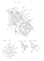
- Fig. 13 is a general sectional view of a gas turbine.
- numeral 1 designates a compressor for compressing air to prepare the air for the combustion and the air for cooling a rotor and blades.
- Numeral 2 designates a turbine casing, and
- numeral 3 designates a number combustors arranged in the turbine casing 2 around the rotor. For example, there are arranged sixteen combustors, each of which is constructed to include a combustion cylinder 3a, a cylinder 3b and a transition cylinder 3c.
- Numeral 100 designates a gas path of the gas turbine, which is constructed to include multistage moving blades 101 and stationary blades 102.
- the moving blades are fixed on the rotor, and the stationary blades are fixed on the side of the turbine casing 2.
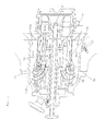
- Fig. 14 is a detailed view of portion G in Fig. 13 and shows the internal structure of the combustor 3.
- numeral 4 designates an inlet passage of the combustor
- numeral 5 designates a main passage or a passage around main nozzles 7.
- a plurality of, e.g., eight main nozzles 7 are arranged in a circular shape.
- Numeral 6 designates a main swirler which is disposed in the passage 5 of the main nozzles 7 for swirling the fluid flowing in the main passage 5 toward the leading end.
- Numeral 8 designates one pilot nozzle, which is disposed at the center and which is provided around it with a pilot swirler 9 as in the main nozzles 7.
- numeral 10 designates a combustion cylinder.
- the air as compressed by the compressor 1, flows, as indicated by 110, from the compressor outlet into the turbine casing 2 and further flows around the inner cylinder of the combustor into the combustor inlet passage 4, as indicated by 110a.
- the air turns around the plurality of main nozzles 7, as indicated by 110b, and flows in the inside into the main passage 5 around the main nozzles 7, as indicated by 110c.
- the air flows around the pilot nozzle 8, as indicated by 110d, and is swirled individually by the main swirler 6 and the pilot swirler 9 until it flows to the individual nozzle leading end portions, as indicated by 110e, for the combustion.
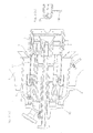
- Fig. 15 is a diagram showing the flow states of the air having flown into the combustor of the prior art.
- the air 110a having flown from the compressor flows, as indicated by 110b, from around the main nozzles 7.
- vortexes 120 are generated by the separation of the flow.
- the present invention has been conceived to provide a gas turbine combustor which is enabled to reduce the combustion instability by guiding the air to flow smoothly into the combustor and by straightening the flow to eliminate the flow disturbances and the concentration change of the fuel.
- the present invention contemplates the following means (1) to (8):
- the air to flow in the combustor flows at first smoothly along the curved face of the flow ring in the cylinder and then passes through the numerous pores of the porous plate so that it is straightened into the homogeneous flow.
- the air flows along the pilot nozzle and the main nozzles to the leading end portion so that the combustion instability, as might otherwise be caused by the concentration difference of the fuel, can be reduced.
- the flow ring is formed into an extended semicircular shape, and the porous plate can be fixed at its periphery on the extended semicircular side face so that the working can be facilitated.
- the flow rings are arranged in multiple stages so that the air is homogeneously guided to flow into the cylinder of the combustor through the multistage circumferential gaps thereby to promote the effects of the aforementioned invention (1) better.
- the inlet portion of the combustor housing portion for the air to flow in is constructed of the wall faces having the corners for protruding the housing portion.
- the air to flow into the combustor is disturbed and is guided in the turbulent state into the flow guide of the leading end portion of the combustor.
- the guide portion is provided so that the wall face of the inlet portion may form the smoothly curved face.
- the air inflow is smoothly turned at the upstream end of the combustor by the funnel-shaped flow guide and is guided into the cylinder by the flow ring.
- the porous plate is disposed downstream of the support for supporting the pilot nozzle and the main nozzles. Even if the flow is disturbed more or less by the support, therefore, these disturbances are straightened by the porous plate so that the air flow is homogenized and introduced into the nozzle leading end portion thereby to ensure the effect to reduce the combustion instability of the aforementioned invention (1) better.
- the flow rings are arranged in multiple stages, and the cylindrical porous plate is arranged in front of the air inlet portion around those flow rings. Therefore, the air to flow into the combustor is straightened into the cylindrical homogeneous flow by the porous plate, and this homogeneous flow is then smoothly guided through the gap between the multistage flow rings into the cylinder of the combustor. In the invention (6), too, the disturbances of the air flow are reduced to reduce the combustion instability.
- the fairings in the space between the individual main nozzles and the pilot nozzle opposed to each other, there is formed the fairings so that the air flows in the gaps between the adjoining fairings and further flows downstream.
- This air flow has a rising flow velocity downward. Therefore, the gap is enlarged from the upstream to the downstream so that the air flow through the fairings is homogenized by that shape.
- the air can flow downstream without any flow disturbance thereby to reduce the combustion instability, as might otherwise be caused by its disturbances.
- the flow guide for guiding the air flow from the compressor outlet to the combustor homogeneously around the combustor.
- the flow ring and the porous plate are disposed at the compressor outlet.
- the flow ring and the porous plate are disposed at the compressor outlet.
- the flow ring and the porous plate to eliminate the air disturbances in the combustor and to reduce the combustion instability.
- the air to flow in the combustor is guided to flow smoothly at the inlet portion of the combustor housing portion by the guide portion of the smooth curve.
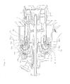
- FIG. 1 shows a gas turbine combustor according to a first embodiment of the invention, (a) a sectional view of the inside, (b) a sectional view of A - A in (a), (c) a sectional view of line B - B in (b), and (d) a modification of (c).
- the structure of the combustor is identical to that of the prior art example shown in Fig. 14 , and the featuring portions of the invention will be mainly described by quoting the common reference numerals.
- numeral 20 designates a flow ring which has a ring shape in a semicircular section and which is so mounted by struts 11 as to cover in a semicircular shape around the end portion of a combustion cylinder 10.
- the flow ring 20 is formed into a circular annular shape by splitting a tube of an internal radius R longitudinally into halves, as shown at (c).
- a punching metal (or a porous plate) 50 which is provided with a number of pores to have an opening ratio of 40% to 60%. This opening ratio is expressed by a/A, if the area of the punching metal is designated by A and if the total area of the pores is designated by a.
- Numeral 51 designates a punching metal rib which is disposed at the end portion all over the circumference of the inner wall of the combustion cylinder 10, as shown at (c) and (d). This punching metal rib 51 is made smaller than the punching metal 50 so that the nozzle assembly may be extracted from the combustion cylinder 10 and may close the surrounding clearance.
- a bulging 54 for eliminating the turbulence of air to flow along the inner wall of the flow ring 20, thereby to smoothen the flow.
- the aforementioned opening ratio is preferred to fall within the range of 40% to 60%, as specified above, because the straightening effect is weakened if it is excessively large and because the pressure loss is augmented if it is excessively small.
- the first embodiment is constructed such that the flow ring 20, the punching metal 50 and the punching metal rib 51 are disposed in the combustor.
- the air flows smoothly into the combustor and is straightened and freed from disturbances or vortexes so that the combustion instability can be suppressed to reduce the vibrations.
- ⁇ P designates a pressure difference between the inlet and the outlet;
- V av an average flow velocity;
- g the gravity.
- Fig. 2 is a diagram showing air flows of the combustor according to the first embodiment thus far described.
- the punching metal 50 and the punching metal rib 51 as shown, an incoming air flow 110a flows in and turns smoothly, as indicated by 110b, along the smooth curve of the flow ring 20 and further flows around main nozzles 7 and a pilot nozzle 8, as indicated by 130a and 130b, without the vortexes or disturbances.
- the fuel concentration is not varied, but the flow is homogenized by the straightening effect of the punching metal 50 and the punching metal rib 51 so that the combustion instability can hardly occur.
- Fig. 3 shows the inside of a gas turbine combustor according to a second embodiment of the invention, and (a) a sectional view and (b) a sectional view of the flow ring.
- numeral 21 designates a flow ring which is formed not to have a semicircular section, as in the flow ring 20 of the first embodiment shown in Figs. 1 and 2 , but to have an extended semicircular shape having a width of an internal diameter R and an enlarged length L.
- the punching metal 50 is fixed at its circumference on the extended side face of the flow ring 21 so that the punching metal rib 51 used in the first embodiment can be dispensed with.
- the remaining construction is identical to that of the first embodiment shown in Figs. 1 and 2 , so that the effects similar to those of the first embodiment can be attained to reduce the combustion instability.
- Fig. 4 is a sectional view of the inside of a gas turbine combustor according to a third embodiment of the invention.
- a two-stage type flow ring 22 is adopted in place of the flow ring 20 of the first embodiment shown in Figs. 1 and 2 .
- the remaining construction has a structure identical to that of the first embodiment.
- the flow ring 22 is constructed by arranging two stages of flow rings 22a and 22b of a semicircular section while holding a passage P of a predetermined width.
- the air is guided to flow in as: an air flow 131 along the upper face of the flow ring 22a on the outer side; an air flow 132 through the passage P formed between 22a and 22b; and an air flow 133 inside of 22b.
- These air flows are so individually straightened by the punching metal 50 and a punching metal rib 51 as to flow around the main nozzles 7 and the pilot nozzle 8 without the vortexes or disturbances toward the leading end.
- Fig. 5 illustrates comparisons of the flows at the flow ring 20 of the first embodiment of the invention and the flows at the flow ring 22 of the third embodiment, (a) with no flow ring, (b) an example of the first embodiment, and (c) an example of the third embodiment.
- the velocity distribution is largely drifted toward the inner circumference.
- the velocity distribution fluctuates, as indicated by V max 1, at the entrance of the main passage, but in (c), the velocity distribution V max 2 is reduced (V max 0 > V max 1 > V max 2).
- Fig. 6 is a sectional view of a gas turbine combustor according to a fourth embodiment of the invention.
- the flow ring 20 is identical to that of the first embodiment shown in Figs. 1 and 2 .
- a bellmouth 60 is disposed around the wall of a turbine casing 2 of an inlet passage 4 of the combustor.
- the inner wall face of the turbine casing 2 around the combustor inlet passage 4 is abruptly changed so that vortexes are easily formed on the surrounding wall face.
- the bellmouth 60 is provided to form the surrounding of the inlet passage 4 into a smoothly curved face so that the air inflow 110a comes in smoothly along the bellmouth 60 and is guided to the flow ring 20. In the inflow process, therefore, there is eliminated the disturbances which might otherwise be caused by the separation of flow on the wall face. In this fourth embodiment, too, there is attained the effect to reduce the combustion instability as in the first embodiment.
- Fig. 7 is a sectional view of a gas turbine combustor according to a fifth embodiment of the invention.
- the flow ring 20 is identical to that shown in Figs. 1 and 2 .
- the punching metal is disposed as the downstream punching metal 52 on the downstream side.
- the punching metal rib 51 is also provided, as in Figs. 1 and 2 .
- an inner cylinder flow guide 70 On the upstream side, there is further provided an inner cylinder flow guide 70.
- This inner cylinder flow guide 70 is such a funnel shape that the enlarged portion is fixed at its circumference on the inner wall of the combustor leading end portion of the turbine casing 2 to have a smoothly curved face in the flow direction and that the reduced portion is fixed around the pilot nozzle.
- the inner cylinder flow guide 70 and the curved face of the flow ring 20 form an air inflow passage, along which the air smoothly flows in, as indicated by 134, and flows in, as indicated by 135, along the circular shape of the flow ring 20 on the inner side of the flow guide 20.
- the air inflow establishes more or less disturbances when it passes through the support 12, but is straightened by the punching metal 52 on the downstream side so that it can flow as a homogeneous flow to the leading end portion thereby to reduce the combustion instability as in the first embodiment.
- the fifth embodiment too, there is attained the effect to reduce the combustion instability remarkably as in the first embodiment.
- Fig. 8 shows a gas turbine combustor according to a sixth embodiment of the invention, (a) a sectional view, and (b) a sectional view of C - C in (a).
- the flow ring is formed into a multistage flow ring 23 so that the air inflow may come smoothly at the upstream inlet to reduce the flow disturbances in the inside.
- the multistage flow ring 23 is constructed, as shown, by arranging an outer one 23a, an intermediate one 23b and an inner one 23c while holding predetermined passages inbetween. These flow rings 23a, 23b and 23c are individually fixed on the struts 11. In the inlet portion, there is further arranged a punching metal 53, which has such a diverging cylindrical shape that its enlarged portion is fixed therearound on the inner wall of the turbine casing and that its other end is connected therearound to the end portion of the combustion cylinder 11.
- the flow ring 23 is halved, as represented by 23a in Fig. 8(b) , at the leading circumferential portion of the punching metal 53 into a larger arcuate portion 23a-1 on the inner side and a portion 23a-2 on the outer circumferential side.
- the remaining flow rings 23b and 23c are given similar constructions.
- the punching metal 53 is preferably constructed to have the opening ratio of 40% to 60%, as in that of the first embodiment shown in Figs. 1 and 2 .
- the punching metal rib can be dispensed with.
- the air inflow is guided in four flows, as indicated by 136, 137, 138 and 139, by the flow rings 23a, 23b and 23c and are straightened at the inlet by the multiple pores of the punching metal 53.
- the air flows then turn smoothly along the individual partitioned passages and enter the inside.
- the air flow is homogeneously divided into the four flows and straightened just before they turn, so that their downstream flows can be hardly disturbed to reduce the combustion instability.
- Fig. 9 shows a gas turbine combustor according to a seventh embodiment of the invention, (a) an entire view, and (b) a partially sectional view of a flow ring of the combustor.
- the combustor inlet is provided with a bellmouth
- the combustor is provided with a flow ring and a punching metal
- the compressor outlet is provided with a compressor outlet flow guide, so that the air to flow into the combustor may be hardly disturbed and may be homogenized to reduce the combustion instability.
- the inlet passage bellmouth 60 is disposed around the inlet, and the punching metal 50 is disposed in the combustor, as has been described with reference to Fig. 6 .
- the flow ring 20 having a semicircular section, as has been described with reference to Fig. 1 .
- a compressor outlet flow guide 75 which is opened to guide the air outward around the rotor from the compressor outlet toward a plurality of combustors on the outer side.
- On the opening portions of the flow guide 75 there are mounted ribs 76, 77 and 78 which are spaced at a predetermined distance for keeping the strength properly.
- the air from the compressor outlet is guided to flow homogeneously, as indicated by 140a and 140b, toward the surrounding of the combustor 2 by the guide of the compressor outlet flow guide 75 and is further guided to flow smoothly into the combustor by the bellmouth 60 at the combustor inlet.
- the flow direction is smoothly turned by the flow guide 20 and is straightened by the punching metal 50 so the air is fed without any disturbance to the main nozzles 7 and to the surrounding of the pilot nozzle 8.
- the guide 75, the bellmouth 60 and the flow ring 20 for guiding the flows smoothly are disposed at the outlet of the compressor 1, the inlet of the combustor and in the combustor.
- Fig. 10 shows a gas turbine combustor according to an eighth embodiment of the invention, (a) a sectional view, and (b) a sectional view of E - E in (a).
- Fig. 11 is a sectional view of F - F at (a) in Fig. 10 and shows a development in the circumferential direction.
- the combustor is provided with the flow ring 20 as in Figs. 1 and 2 .
- fairings 80 made of a filler are disposed in a predetermined section upstream of the pilot nozzle 8 and the eight main nozzles arranged in a circumferential shape.
- the fairings 80 are formed, as shown at (b), by filling the space, as hatched, between the main nozzles 7 and the pilot nozzle 8.
- the fairings 80 are so elongated in the longitudinal direction to the vicinity of the leading end portion of the flow ring 20 and the combustion cylinder 11 that the downstream side 80b is made thinner than the upstream side 80a, as shown in section E - E in Fig. 11 , and that a gap d between the adjoining fairings is enlarged downstream.
- the reason for this shape is that the air flow velocity grows the higher toward the downstream from the upstream so that the flow may be smoothed to reduce the disturbances of the flow velocity by making the width d of the space the larger to the forward.
- the air inflow will turn in the combustion and will flow through the gap between the main nozzles 7 and the pilot nozzle 8 downstream of the upstream end of the fairings 80.
- this gap is filled with the fairings 80.
- the gap is enlarged at the leading end portion between the adjoining main nozzles 7.
- the passage is enlarged to smoothen the air flow so that the air flows along the surrounding of the pilot nozzle 8 and flows out of the leading end portion.
- the air to flow in from the outside of the main nozzles 7 turns smoothly at the flow ring 20, as in the first embodiment described with reference to Fig. 1 , and flows in. Therefore, the disturbances of the air to flow upstream around the main nozzles 7 and around the pilot nozzle 8 are minimized so that it can be fed as the homogeneous air flow to the nozzle leading end portion to reduce the combustion instability.
- Fig. 12 is a diagram illustrating the effects of the invention.
- the experimental values of the seventh embodiment, as has been described with reference to Fig. 9 are representatively plotted, and the abscissa indicates a load whereas the ordinate indicates air pressure fluctuations of the combustor.
- black circles indicate the data of the combustor of the prior art, and white circles indicate the data of the case in which there are provided the flow guide 20, the punching metal 50, the punching metal rib 51 and the compressor outlet flow guide 75 as shown in the Fig. 9 .
- black circles indicate the data of the combustor of the prior art
- white circles indicate the data of the case in which there are provided the flow guide 20, the punching metal 50, the punching metal rib 51 and the compressor outlet flow guide 75 as shown in the Fig. 9 .
- it is found that the air pressure fluctuations are reduced if the flow guide 20, the bellmouth 60 and the compressor inlet guide 75 are provided in addition to the punching metal.
- the air to flow in the combustor flows at first smoothly along the curved face of the flow ring in the cylinder and then passes through the numerous pores of the porous plate so that it is straightened into the homogeneous flow.
- the air flows along the pilot nozzle and the main nozzles to the leading end portion so that the combustion instability, as might otherwise be caused by the concentration difference of the fuel, can be reduced.
- the flow ring is formed into an extended semicircular shape, and the porous plate can be fixed at its periphery on the extended elliptical side face so that the working can be facilitated.
- the flow rings are arranged in multiple stages so that the air is homogeneously guided to flow into the cylinder of the combustor through the multistage circumferential gaps thereby to promote the effects of the aforementioned invention (1) better.
- the inlet portion of the combustor housing portion for the air to flow in is constructed of the wall faces having the corners for protruding the housing portion.
- the air to flow into the combustor is disturbed and is guided in the turbulent state into the flow guide of the leading end portion of the combustor.
- the guide portion is provided so that the wall face of the inlet portion may form the smoothly curved face.
- the air inflow is smoothly turned at the upstream end of the combustor by the funnel-shaped flow guide and is guided into the cylinder by the flow ring.
- the porous plate is disposed downstream of the support for supporting the pilot nozzle and the main nozzles. Even if the flow is disturbed more or less by the support, therefore, these disturbances are straightened by the porous plate so that the air flow is homogenized and introduced into the nozzle leading end portion thereby to ensure the effect to reduce the combustion instability of the aforementioned invention (1) better.
- the flow rings are arranged in multiple stages, and the cylindrical porous plate is arranged in front of the air inlet portion around those flow rings. Therefore, the air to flow into the combustor is straightened into the cylindrical homogeneous flow by the porous plate, and this homogeneous flow is then smoothly guided through the gap between the multistage flow rings into the cylinder of the combustor.
- the fairings in the space between the individual main nozzles and the pilot nozzle opposed to each other, there is formed the fairings so that the air flows in the gaps between the adjoining fairings and further flows downstream.
- This air flow has a rising flow velocity downward. Therefore, the gap is enlarged from the upstream to the downstream so that the air flow through the fairings is homogenized by that shape.
- the air can flow downstream without any flow disturbance thereby to reduce the combustion instability, as might otherwise be caused by its disturbances.
- the flow guide for guiding the air flow from the compressor outlet to the combustor homogeneously around the combustor.
- the flow ring and the porous plate are disposed at the compressor outlet.
- the flow ring and the porous plate are disposed at the compressor outlet.
- the flow ring and the porous plate to eliminate the air disturbances in the combustor and to reduce the combustion instability.
- the air to flow in the combustor is guided to flow smoothly at the inlet portion of the combustor housing portion by the guide portion of the smooth curve.
Landscapes
- Engineering & Computer Science (AREA)
- Chemical & Material Sciences (AREA)
- Combustion & Propulsion (AREA)
- Mechanical Engineering (AREA)
- General Engineering & Computer Science (AREA)
- Spray-Type Burners (AREA)
Applications Claiming Priority (2)
| Application Number | Priority Date | Filing Date | Title |
|---|---|---|---|
| JP16252099A JP3364169B2 (ja) | 1999-06-09 | 1999-06-09 | ガスタービン及びその燃焼器 |
| EP00935589A EP1103767B1 (de) | 1999-06-09 | 2000-06-08 | Gasturbinenbrennkammer mit strömungsleitvorrichtung |
Related Parent Applications (2)
| Application Number | Title | Priority Date | Filing Date |
|---|---|---|---|
| EP00935589.2 Division | 2000-06-08 | ||
| EP00935589A Division EP1103767B1 (de) | 1999-06-09 | 2000-06-08 | Gasturbinenbrennkammer mit strömungsleitvorrichtung |
Publications (3)
| Publication Number | Publication Date |
|---|---|
| EP2189722A2 true EP2189722A2 (de) | 2010-05-26 |
| EP2189722A3 EP2189722A3 (de) | 2013-08-07 |
| EP2189722B1 EP2189722B1 (de) | 2015-08-12 |
Family
ID=15756193
Family Applications (2)
| Application Number | Title | Priority Date | Filing Date |
|---|---|---|---|
| EP10155401.2A Expired - Lifetime EP2189722B1 (de) | 1999-06-09 | 2000-06-08 | Gasturbine mit brennkammer |
| EP00935589A Expired - Lifetime EP1103767B1 (de) | 1999-06-09 | 2000-06-08 | Gasturbinenbrennkammer mit strömungsleitvorrichtung |
Family Applications After (1)
| Application Number | Title | Priority Date | Filing Date |
|---|---|---|---|
| EP00935589A Expired - Lifetime EP1103767B1 (de) | 1999-06-09 | 2000-06-08 | Gasturbinenbrennkammer mit strömungsleitvorrichtung |
Country Status (5)
| Country | Link |
|---|---|
| US (1) | US6634175B1 (de) |
| EP (2) | EP2189722B1 (de) |
| JP (1) | JP3364169B2 (de) |
| CA (1) | CA2340107C (de) |
| WO (1) | WO2000075573A1 (de) |
Cited By (1)
| Publication number | Priority date | Publication date | Assignee | Title |
|---|---|---|---|---|
| WO2019201577A1 (de) | 2018-04-18 | 2019-10-24 | Siemens Aktiengesellschaft | Brenner mit selektiver anpassung des bohrungsmusters für die gaseindüsung |
Families Citing this family (71)
| Publication number | Priority date | Publication date | Assignee | Title |
|---|---|---|---|---|
| JP4610800B2 (ja) | 2001-06-29 | 2011-01-12 | 三菱重工業株式会社 | ガスタービン燃焼器 |
| JP3986348B2 (ja) * | 2001-06-29 | 2007-10-03 | 三菱重工業株式会社 | ガスタービン燃焼器の燃料供給ノズルおよびガスタービン燃焼器並びにガスタービン |
| JP3495730B2 (ja) * | 2002-04-15 | 2004-02-09 | 三菱重工業株式会社 | ガスタービンの燃焼器 |
| DE10219354A1 (de) * | 2002-04-30 | 2003-11-13 | Rolls Royce Deutschland | Gasturbinenbrennkammer mit gezielter Kraftstoffeinbringung zur Verbesserung der Homogenität des Kraftstoff-Luft-Gemisches |
| JP4070758B2 (ja) * | 2004-09-10 | 2008-04-02 | 三菱重工業株式会社 | ガスタービン燃焼器 |
| JP4015656B2 (ja) * | 2004-11-17 | 2007-11-28 | 三菱重工業株式会社 | ガスタービン燃焼器 |
| US7624578B2 (en) * | 2005-09-30 | 2009-12-01 | General Electric Company | Method and apparatus for generating combustion products within a gas turbine engine |
| US7523614B2 (en) * | 2006-02-27 | 2009-04-28 | Mitsubishi Heavy Industries, Ltd. | Combustor |
| US7540153B2 (en) * | 2006-02-27 | 2009-06-02 | Mitsubishi Heavy Industries Ltd. | Combustor |
| US7770395B2 (en) | 2006-02-27 | 2010-08-10 | Mitsubishi Heavy Industries, Ltd. | Combustor |
| US7540152B2 (en) | 2006-02-27 | 2009-06-02 | Mitsubishi Heavy Industries, Ltd. | Combustor |
| US7762074B2 (en) * | 2006-04-04 | 2010-07-27 | Siemens Energy, Inc. | Air flow conditioner for a combustor can of a gas turbine engine |
| US20070277530A1 (en) * | 2006-05-31 | 2007-12-06 | Constantin Alexandru Dinu | Inlet flow conditioner for gas turbine engine fuel nozzle |
| JP5054988B2 (ja) * | 2007-01-24 | 2012-10-24 | 三菱重工業株式会社 | 燃焼器 |
| WO2009007283A2 (de) * | 2007-07-09 | 2009-01-15 | Siemens Aktiengesellschaft | Gasturbinenbrenner |
| DE102007043626A1 (de) * | 2007-09-13 | 2009-03-19 | Rolls-Royce Deutschland Ltd & Co Kg | Gasturbinenmagerbrenner mit Kraftstoffdüse mit kontrollierter Kraftstoffinhomogenität |
| US20090173074A1 (en) * | 2008-01-03 | 2009-07-09 | General Electric Company | Integrated fuel nozzle ifc |
| JP4918509B2 (ja) * | 2008-02-15 | 2012-04-18 | 三菱重工業株式会社 | 燃焼器 |
| JP5276345B2 (ja) | 2008-03-28 | 2013-08-28 | 三菱重工業株式会社 | ガスタービン及びガスタービンの燃焼器挿入孔形成方法 |
| US8061142B2 (en) * | 2008-04-11 | 2011-11-22 | General Electric Company | Mixer for a combustor |
| US8806871B2 (en) * | 2008-04-11 | 2014-08-19 | General Electric Company | Fuel nozzle |
| US20090255120A1 (en) * | 2008-04-11 | 2009-10-15 | General Electric Company | Method of assembling a fuel nozzle |
| US9188341B2 (en) | 2008-04-11 | 2015-11-17 | General Electric Company | Fuel nozzle |
| US20090255256A1 (en) * | 2008-04-11 | 2009-10-15 | General Electric Company | Method of manufacturing combustor components |
| AT506592B1 (de) | 2008-08-26 | 2009-10-15 | Edmund Ing Lorenz | Verbrennungsturbine mit diskontinuierlicher verbrennung |
| US8234872B2 (en) * | 2009-05-01 | 2012-08-07 | General Electric Company | Turbine air flow conditioner |
| US20110000215A1 (en) * | 2009-07-01 | 2011-01-06 | General Electric Company | Combustor Can Flow Conditioner |
| CN102422083B (zh) * | 2009-08-13 | 2014-07-16 | 三菱重工业株式会社 | 燃烧器 |
| US8402763B2 (en) * | 2009-10-26 | 2013-03-26 | General Electric Company | Combustor headend guide vanes to reduce flow maldistribution into multi-nozzle arrangement |
| US8371123B2 (en) * | 2009-10-28 | 2013-02-12 | General Electric Company | Apparatus for conditioning airflow through a nozzle |
| EP2327933A1 (de) * | 2009-11-30 | 2011-06-01 | Siemens Aktiengesellschaft | Brenneranordnung |
| US20120024985A1 (en) * | 2010-08-02 | 2012-02-02 | General Electric Company | Integrated fuel nozzle and inlet flow conditioner and related method |
| NL2005381C2 (en) | 2010-09-21 | 2012-03-28 | Micro Turbine Technology B V | Combustor with a single limited fuel-air mixing burner and recuperated micro gas turbine. |
| US20120144832A1 (en) * | 2010-12-10 | 2012-06-14 | General Electric Company | Passive air-fuel mixing prechamber |
| US8944141B2 (en) | 2010-12-22 | 2015-02-03 | United Technologies Corporation | Drill to flow mini core |
| JP5766444B2 (ja) * | 2011-01-14 | 2015-08-19 | 三菱日立パワーシステムズ株式会社 | 燃焼器およびガスタービン |
| JP5653774B2 (ja) * | 2011-01-27 | 2015-01-14 | 三菱重工業株式会社 | ガスタービン燃焼器 |
| US20120305677A1 (en) * | 2011-06-06 | 2012-12-06 | General Electric Company | System for conditioning flow through a nozzle |
| CN102323374A (zh) * | 2011-06-09 | 2012-01-18 | 中国科学技术大学 | 开放空间粉尘连续吹喷预混燃烧实验系统 |
| US9291102B2 (en) | 2011-09-07 | 2016-03-22 | Siemens Energy, Inc. | Interface ring for gas turbine fuel nozzle assemblies |
| US8950188B2 (en) * | 2011-09-09 | 2015-02-10 | General Electric Company | Turning guide for combustion fuel nozzle in gas turbine and method to turn fuel flow entering combustion chamber |
| US20130081397A1 (en) * | 2011-10-04 | 2013-04-04 | Brandon Taylor Overby | Forward casing with a circumferential sloped surface and a combustor assembly including same |
| CN103917827B (zh) * | 2011-11-16 | 2016-07-13 | 三菱日立电力系统株式会社 | 燃气涡轮燃烧器 |
| JP5984445B2 (ja) * | 2012-03-23 | 2016-09-06 | 三菱日立パワーシステムズ株式会社 | 燃焼器 |
| DE102012216080A1 (de) | 2012-08-17 | 2014-02-20 | Dürr Systems GmbH | Brenner |
| US10378456B2 (en) | 2012-10-01 | 2019-08-13 | Ansaldo Energia Switzerland AG | Method of operating a multi-stage flamesheet combustor |
| US9347669B2 (en) * | 2012-10-01 | 2016-05-24 | Alstom Technology Ltd. | Variable length combustor dome extension for improved operability |
| US10060630B2 (en) | 2012-10-01 | 2018-08-28 | Ansaldo Energia Ip Uk Limited | Flamesheet combustor contoured liner |
| US9897317B2 (en) | 2012-10-01 | 2018-02-20 | Ansaldo Energia Ip Uk Limited | Thermally free liner retention mechanism |
| US9546789B2 (en) | 2013-03-15 | 2017-01-17 | General Electric Company | System having a multi-tube fuel nozzle |
| US9291352B2 (en) | 2013-03-15 | 2016-03-22 | General Electric Company | System having a multi-tube fuel nozzle with an inlet flow conditioner |
| US9303873B2 (en) | 2013-03-15 | 2016-04-05 | General Electric Company | System having a multi-tube fuel nozzle with a fuel nozzle housing |
| US9784452B2 (en) | 2013-03-15 | 2017-10-10 | General Electric Company | System having a multi-tube fuel nozzle with an aft plate assembly |
| US9316397B2 (en) | 2013-03-15 | 2016-04-19 | General Electric Company | System and method for sealing a fuel nozzle |
| JP6228434B2 (ja) * | 2013-11-15 | 2017-11-08 | 三菱日立パワーシステムズ株式会社 | ガスタービン燃焼器 |
| CA2931246C (en) | 2013-11-27 | 2019-09-24 | General Electric Company | Fuel nozzle with fluid lock and purge apparatus |
| US10451282B2 (en) | 2013-12-23 | 2019-10-22 | General Electric Company | Fuel nozzle structure for air assist injection |
| CN105829802B (zh) | 2013-12-23 | 2018-02-23 | 通用电气公司 | 具有柔性支承结构的燃料喷嘴 |
| KR102405991B1 (ko) * | 2014-11-21 | 2022-06-10 | 에이치2 아이피 유케이 리미티드 | 화염시트 연소기 윤곽형 라이너 |
| KR101820869B1 (ko) * | 2015-06-30 | 2018-01-22 | 두산중공업 주식회사 | 유체 가이드를 포함한 연소기 |
| JP6768306B2 (ja) | 2016-02-29 | 2020-10-14 | 三菱パワー株式会社 | 燃焼器、ガスタービン |
| KR101770313B1 (ko) * | 2016-06-21 | 2017-08-22 | 두산중공업 주식회사 | 에어플로우 가이드를 포함하는 가스 터빈용 연소기 |
| US10677466B2 (en) | 2016-10-13 | 2020-06-09 | General Electric Company | Combustor inlet flow conditioner |
| KR101900192B1 (ko) * | 2017-04-27 | 2018-09-18 | 두산중공업 주식회사 | 연료 노즐 조립체, 이를 포함하는 연료 노즐 모듈 및 가스 터빈 |
| CN108869041B (zh) * | 2017-05-12 | 2020-07-14 | 中国联合重型燃气轮机技术有限公司 | 用于燃气轮机的前端转向勺状件 |
| JP6895867B2 (ja) * | 2017-10-27 | 2021-06-30 | 三菱パワー株式会社 | ガスタービン燃焼器、ガスタービン |
| JP7112342B2 (ja) * | 2019-01-25 | 2022-08-03 | 三菱重工業株式会社 | ガスタービン燃焼器及びガスタービン |
| KR102097029B1 (ko) * | 2019-05-13 | 2020-04-03 | 두산중공업 주식회사 | 연소기 및 이를 포함하는 가스 터빈 |
| DE102020203955A1 (de) | 2020-03-26 | 2021-09-30 | Rolls-Royce Deutschland Ltd & Co Kg | Brennkammergehäuse und Herstellungsverfahren |
| KR102340397B1 (ko) * | 2020-05-07 | 2021-12-15 | 두산중공업 주식회사 | 연소기 및 이를 포함하는 가스 터빈 |
| CN113739203B (zh) * | 2021-09-13 | 2023-03-10 | 中国联合重型燃气轮机技术有限公司 | 用于燃烧器的罩帽组件 |
Family Cites Families (13)
| Publication number | Priority date | Publication date | Assignee | Title |
|---|---|---|---|---|
| US3233866A (en) * | 1958-09-02 | 1966-02-08 | Davidovic Vlastimir | Cooled gas turbines |
| US4428191A (en) * | 1964-10-01 | 1984-01-31 | Rolls Royce Limited | Fuel combustion in ducted flow |
| US3589128A (en) * | 1970-02-02 | 1971-06-29 | Avco Corp | Cooling arrangement for a reverse flow gas turbine combustor |
| DE2937631A1 (de) * | 1979-09-18 | 1981-04-02 | Daimler-Benz Ag, 7000 Stuttgart | Brennkammer fuer gasturbinen |
| JP2544470B2 (ja) * | 1989-02-03 | 1996-10-16 | 株式会社日立製作所 | ガスタ―ビン燃焼器及びその運転方法 |
| JPH07198143A (ja) | 1994-01-12 | 1995-08-01 | Hitachi Ltd | ガスタービン燃焼器 |
| JP3183053B2 (ja) * | 1994-07-20 | 2001-07-03 | 株式会社日立製作所 | ガスタービン燃焼器及びガスタービン |
| JPH08135969A (ja) | 1994-11-08 | 1996-05-31 | Hitachi Ltd | ガスタービン燃焼器の空気流量調節器 |
| US5836164A (en) * | 1995-01-30 | 1998-11-17 | Hitachi, Ltd. | Gas turbine combustor |
| JPH09184630A (ja) | 1996-01-04 | 1997-07-15 | Hitachi Ltd | ガスタービン燃焼器 |
| JP3448190B2 (ja) | 1997-08-29 | 2003-09-16 | 三菱重工業株式会社 | ガスタービンの燃焼器 |
| JP3592912B2 (ja) | 1997-11-13 | 2004-11-24 | 三菱重工業株式会社 | ガスタービン燃焼器 |
| US6082111A (en) * | 1998-06-11 | 2000-07-04 | Siemens Westinghouse Power Corporation | Annular premix section for dry low-NOx combustors |
-
1999
- 1999-06-09 JP JP16252099A patent/JP3364169B2/ja not_active Expired - Lifetime
-
2000
- 2000-06-08 US US09/762,598 patent/US6634175B1/en not_active Expired - Lifetime
- 2000-06-08 EP EP10155401.2A patent/EP2189722B1/de not_active Expired - Lifetime
- 2000-06-08 EP EP00935589A patent/EP1103767B1/de not_active Expired - Lifetime
- 2000-06-08 CA CA002340107A patent/CA2340107C/en not_active Expired - Fee Related
- 2000-06-08 WO PCT/JP2000/003716 patent/WO2000075573A1/ja active Application Filing
Non-Patent Citations (1)
| Title |
|---|
| None |
Cited By (2)
| Publication number | Priority date | Publication date | Assignee | Title |
|---|---|---|---|---|
| WO2019201577A1 (de) | 2018-04-18 | 2019-10-24 | Siemens Aktiengesellschaft | Brenner mit selektiver anpassung des bohrungsmusters für die gaseindüsung |
| DE102018205874A1 (de) | 2018-04-18 | 2019-10-24 | Siemens Aktiengesellschaft | Brenner mit selektiver Anpassung des Bohrungsmusters für die Gaseindüsung |
Also Published As
| Publication number | Publication date |
|---|---|
| EP1103767A4 (de) | 2009-08-26 |
| EP2189722B1 (de) | 2015-08-12 |
| EP2189722A3 (de) | 2013-08-07 |
| JP3364169B2 (ja) | 2003-01-08 |
| CA2340107A1 (en) | 2000-12-14 |
| US6634175B1 (en) | 2003-10-21 |
| EP1103767A1 (de) | 2001-05-30 |
| CA2340107C (en) | 2005-08-16 |
| JP2000346361A (ja) | 2000-12-15 |
| EP1103767B1 (de) | 2012-07-25 |
| WO2000075573A1 (en) | 2000-12-14 |
Similar Documents
| Publication | Publication Date | Title |
|---|---|---|
| EP2189722B1 (de) | Gasturbine mit brennkammer | |
| US5257906A (en) | Exhaust system for a turbomachine | |
| US7575411B2 (en) | Engine intake air compressor having multiple inlets and method | |
| CN1214191C (zh) | 离心压气机的消涡器 | |
| US3861826A (en) | Cascade diffuser having thin, straight vanes | |
| US20100158684A1 (en) | Vane assembly configured for turning a flow in a gas turbine engine, a stator component comprising the vane assembly, a gas turbine and an aircraft jet engine | |
| EP3536972B1 (de) | Zentrifugalverdichter und turbolader | |
| CN107109947B (zh) | 飞机涡轮发动机的定子 | |
| EP0886070A1 (de) | Kreiselverdichter sowie diffusor für kreiselverdichter | |
| US7828514B2 (en) | Rotor for an engine | |
| US8206097B2 (en) | Compressor | |
| KR19980064736A (ko) | 축류 터빈의 터빈 노즐 및 터빈 동익 | |
| EP2994647B1 (de) | Kreiselverdichter mit einlasskanal mit drallerzeugern | |
| JP5535562B2 (ja) | 排出スクロール及びターボ機械 | |
| US8661829B2 (en) | Aerodynamic shroud for the back of a combustion chamber of a turbomachine | |
| CN101180468A (zh) | 用于离心式压缩机的流动稳定系统 | |
| CN101382297A (zh) | 一种采用螺线气流的涡轮机燃烧室 | |
| EP3832144B1 (de) | Diffusorrohr mit radial nach aussen gerichtetem ausgang | |
| JP6632510B2 (ja) | 蒸気タービンの排気室、蒸気タービン排気室用のフローガイド、及び、蒸気タービン | |
| EP3760849B1 (de) | Zentrifugalverdichter und turbolader | |
| US20180156450A1 (en) | Fuel nozzle of a gas turbine with a swirl generator | |
| ITRM20000234A1 (it) | Compressore radiale con fenditure alle pareti, in particolare per autoveicoli. | |
| US9175690B2 (en) | Compressor | |
| US4356693A (en) | Gas turbine engine combustion chambers | |
| KR100433324B1 (ko) | 원심 압축기 |
Legal Events
| Date | Code | Title | Description |
|---|---|---|---|
| PUAI | Public reference made under article 153(3) epc to a published international application that has entered the european phase |
Free format text: ORIGINAL CODE: 0009012 |
|
| 17P | Request for examination filed |
Effective date: 20100303 |
|
| AC | Divisional application: reference to earlier application |
Ref document number: 1103767 Country of ref document: EP Kind code of ref document: P |
|
| AK | Designated contracting states |
Kind code of ref document: A2 Designated state(s): CH DE FR GB IT LI |
|
| REG | Reference to a national code |
Ref country code: HK Ref legal event code: DE Ref document number: 1140004 Country of ref document: HK |
|
| PUAL | Search report despatched |
Free format text: ORIGINAL CODE: 0009013 |
|
| AK | Designated contracting states |
Kind code of ref document: A3 Designated state(s): CH DE FR GB IT LI |
|
| RIC1 | Information provided on ipc code assigned before grant |
Ipc: F23R 3/04 20060101AFI20130702BHEP |
|
| GRAP | Despatch of communication of intention to grant a patent |
Free format text: ORIGINAL CODE: EPIDOSNIGR1 |
|
| INTG | Intention to grant announced |
Effective date: 20150306 |
|
| RAP1 | Party data changed (applicant data changed or rights of an application transferred) |
Owner name: MITSUBISHI HITACHI POWER SYSTEMS, LTD. |
|
| RAP1 | Party data changed (applicant data changed or rights of an application transferred) |
Owner name: MITSUBISHI HITACHI POWER SYSTEMS, LTD. |
|
| GRAS | Grant fee paid |
Free format text: ORIGINAL CODE: EPIDOSNIGR3 |
|
| GRAA | (expected) grant |
Free format text: ORIGINAL CODE: 0009210 |
|
| AC | Divisional application: reference to earlier application |
Ref document number: 1103767 Country of ref document: EP Kind code of ref document: P |
|
| AK | Designated contracting states |
Kind code of ref document: B1 Designated state(s): CH DE FR GB IT LI |
|
| REG | Reference to a national code |
Ref country code: GB Ref legal event code: FG4D |
|
| REG | Reference to a national code |
Ref country code: CH Ref legal event code: EP |
|
| REG | Reference to a national code |
Ref country code: DE Ref legal event code: R096 Ref document number: 60049044 Country of ref document: DE |
|
| PG25 | Lapsed in a contracting state [announced via postgrant information from national office to epo] |
Ref country code: IT Free format text: LAPSE BECAUSE OF FAILURE TO SUBMIT A TRANSLATION OF THE DESCRIPTION OR TO PAY THE FEE WITHIN THE PRESCRIBED TIME-LIMIT Effective date: 20150812 |
|
| REG | Reference to a national code |
Ref country code: DE Ref legal event code: R097 Ref document number: 60049044 Country of ref document: DE |
|
| PLBE | No opposition filed within time limit |
Free format text: ORIGINAL CODE: 0009261 |
|
| STAA | Information on the status of an ep patent application or granted ep patent |
Free format text: STATUS: NO OPPOSITION FILED WITHIN TIME LIMIT |
|
| 26N | No opposition filed |
Effective date: 20160513 |
|
| REG | Reference to a national code |
Ref country code: DE Ref legal event code: R119 Ref document number: 60049044 Country of ref document: DE |
|
| REG | Reference to a national code |
Ref country code: HK Ref legal event code: WD Ref document number: 1140004 Country of ref document: HK |
|
| REG | Reference to a national code |
Ref country code: CH Ref legal event code: PL |
|
| GBPC | Gb: european patent ceased through non-payment of renewal fee |
Effective date: 20160608 |
|
| REG | Reference to a national code |
Ref country code: FR Ref legal event code: ST Effective date: 20170228 |
|
| PG25 | Lapsed in a contracting state [announced via postgrant information from national office to epo] |
Ref country code: DE Free format text: LAPSE BECAUSE OF NON-PAYMENT OF DUE FEES Effective date: 20170103 Ref country code: FR Free format text: LAPSE BECAUSE OF NON-PAYMENT OF DUE FEES Effective date: 20160630 Ref country code: LI Free format text: LAPSE BECAUSE OF NON-PAYMENT OF DUE FEES Effective date: 20160630 Ref country code: CH Free format text: LAPSE BECAUSE OF NON-PAYMENT OF DUE FEES Effective date: 20160630 |
|
| PG25 | Lapsed in a contracting state [announced via postgrant information from national office to epo] |
Ref country code: GB Free format text: LAPSE BECAUSE OF NON-PAYMENT OF DUE FEES Effective date: 20160608 |