EP2188196B1 - Method for conveying waste - Google Patents
Method for conveying waste Download PDFInfo
- Publication number
- EP2188196B1 EP2188196B1 EP08805422.6A EP08805422A EP2188196B1 EP 2188196 B1 EP2188196 B1 EP 2188196B1 EP 08805422 A EP08805422 A EP 08805422A EP 2188196 B1 EP2188196 B1 EP 2188196B1
- Authority
- EP
- European Patent Office
- Prior art keywords
- waste
- container
- tunnel
- conveying
- transport
- Prior art date
- Legal status (The legal status is an assumption and is not a legal conclusion. Google has not performed a legal analysis and makes no representation as to the accuracy of the status listed.)
- Active
Links
- 239000002699 waste material Substances 0.000 title claims description 214
- 238000000034 method Methods 0.000 title claims description 30
- 238000010276 construction Methods 0.000 description 5
- 239000010791 domestic waste Substances 0.000 description 3
- 239000000463 material Substances 0.000 description 3
- 230000007423 decrease Effects 0.000 description 2
- -1 bin bags Substances 0.000 description 1
- 238000004140 cleaning Methods 0.000 description 1
- 238000002485 combustion reaction Methods 0.000 description 1
- 230000006378 damage Effects 0.000 description 1
- 230000001419 dependent effect Effects 0.000 description 1
- 230000001627 detrimental effect Effects 0.000 description 1
- 230000009977 dual effect Effects 0.000 description 1
- 230000000694 effects Effects 0.000 description 1
- 230000007613 environmental effect Effects 0.000 description 1
- 230000005484 gravity Effects 0.000 description 1
- 230000001788 irregular Effects 0.000 description 1
- 230000003137 locomotive effect Effects 0.000 description 1
- 238000012423 maintenance Methods 0.000 description 1
- 239000010813 municipal solid waste Substances 0.000 description 1
- 238000004064 recycling Methods 0.000 description 1
- 230000001105 regulatory effect Effects 0.000 description 1
Images

Classifications
-
- B—PERFORMING OPERATIONS; TRANSPORTING
- B65—CONVEYING; PACKING; STORING; HANDLING THIN OR FILAMENTARY MATERIAL
- B65F—GATHERING OR REMOVAL OF DOMESTIC OR LIKE REFUSE
- B65F5/00—Gathering or removal of refuse otherwise than by receptacles or vehicles
- B65F5/005—Gathering or removal of refuse otherwise than by receptacles or vehicles by pneumatic means, e.g. by suction
-
- E—FIXED CONSTRUCTIONS
- E04—BUILDING
- E04F—FINISHING WORK ON BUILDINGS, e.g. STAIRS, FLOORS
- E04F17/00—Vertical ducts; Channels, e.g. for drainage
- E04F17/10—Arrangements in buildings for the disposal of refuse
Definitions
- the invention relates to a method for conveying waste according to the preamble of claim 1.
- the invention relates generally to collecting and conveying waste, such as conveying household waste, particularly treating urban waste.
- waste rooms are located waste containers in which household waste is brought, emptied to waste trucks manually and the waste truck takes the waste then to a landfill.
- this causes problems for traffic, the environment and hygiene etc as waste trucks drive around on the roads picking up waste and taking it to the landfill.
- Document FI 50 891 C discloses a system for pneumatically transferring different types of goods through common piping.
- the system operates automatically to direct one type of goods to one container, for example goods such as trash which is to be held for destruction, and the other type of goods to another container, for example goods such as laundry which is to be held for recycling.
- the automatic routing of the goods is preferably controlled by separate inlets for the two types of goods, such that the goods inserted into one inlet are automatically routed to one container and goods inserted into the other inlet are automatically routed to the other container.
- the system provides an intermediate collector for each type of goods adjacent the inlets so that the goods deposited in the respective inlets may be separately accumulated prior to being transferred to the containers.
- the common piping is confined between the dual inlets and the collectors; in the second, the common piping is confined to between the collectors and the containers; and in the third system, the common piping is provided between the inlets and the collectors, and also between the collectors and the containers.
- a common suction is provided to transport the goods from the inlets through the collectors to the containers.
- An object of this invention is to achieve a totally novel method for a conveying waste by means of which the disadvantages of known arrangements are avoided.
- the invention is based on an idea in which a typically existing tunnel system, such as a traffic tunnel system, advantageously an underground tunnel system, is utilised in collecting and conveying waste.
- a typically existing tunnel system such as a traffic tunnel system, advantageously an underground tunnel system
- the object of the present invention is a method for conveying waste according to claim 1.
- a typically existing tunnel system such as a traffic tunnel system, advantageously an underground tunnel system, is utilised in collecting and conveying waste, an environmentally-friendly and cost-effective waste conveying system, which also otherwise minimises disadvantages, is provided.
- the profitability of tunnel construction and/or underground construction can also be improved, because in addition to conventional traffic, such as passenger traffic, it is possible to convey waste according to the invention in the tunnels, most advantageously during slow traffic, such as during the night.
- An advantage of the method according to the invention is also that the dense social structure is typically located along the network of tunnel systems, such as underground, whereby it is as well cost-effective to handle waste management by means of the method according to the invention by utilising the ready tunnel infrastructure.
- the invention in an extraordinary way combines a piping conveying system of waste and a conveying path enabled by tunnels which can be also utilised in conveying waste.
- the tunnel used by the method of the invention can also be a branch of a tunnel which is solely intended for waste conveyance but which is connected to a tunnel network, such as a traffic tunnel network, most advantageously an underground tunnel network.
- a tunnel network such as a traffic tunnel network
- an underground tunnel usually means a tunnel and an underground part of a traffic system particularly conventional in big cities in which underground trains or equivalent travel and which is typically constructed at least partially under ground.
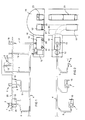
- Figs. 1 and 2 schematically show a waste conveying system.
- the figure shows part of a tunnel 20, such as a traffic tunnel, advantageously an underground tunnel, in a recess of which is arranged a waste space 16, particularly a waste room.
- the tunnel and its vehicle passage is utilised in conveying waste.
- waste spaces 16 are arranged at suitable points, either in the tunnel space 20 and/or a space connected to it and/or such that there is a conveying connection from the waste spaces 16 for conveying a waste container in the tunnel space 20.
- the waste space can thus be a branch of a tunnel which is solely intended for waste conveyance but which is connected to an underground tunnel network.
- the waste container/transport container can be conveyed aboard a waste transport carriage or a transport truck and taken to a further treatment site.
- the waste container 10 is provided with wheels 24 and is thus a waste transport carriage which can be conveyed in the tunnel e.g. along a track pair 21, 22.
- the waste transport carriage can be separate or part of a waste transport train which is arranged to travel in the tunnel.
- the figure includes another waste container 10' provided with wheels i.e. waste transport carriage in the actual tunnel space 20.
- a vehicle passage particularly the track pair 21, 22, which traffic units 23 of the underground system, such as underground trains and underground carriages, utilise for travelling.
- the tunnel is used for conveying waste particularly when other traffic in the tunnel, such as the passenger traffic of the underground, is slow or stopped.
- the tunnel such as a traffic tunnel, advantageously an underground tunnel, is thus used as part of the conveying system of waste.
- reference number 1 designates a feed station of waste material intended for conveyance from which station waste, such as household waste, is fed to the conveying system.
- the feed station 1 can be a feed opening of a waste chute 5 inside a building which is covered by an openable and closable hatch 7.
- feed points are shown simplified when set on top of a ground surface 25, whereby a conveying piping mainly passes bellow the surface 25.
- a suction point 8 can be used in connection with which there is e.g. a feed funnel 9.
- the system typically comprises several feed stations 1 or suction points 8 from which waste material intended for conveyance is fed to the conveying piping 2, 3, 4.
- the conveying piping comprises a main conveying pipe 4 into which several feed stations 1 and/or suction points 8 can have been connected through feed pipes 2, 3.
- the fed waste material is conveyed along the conveying piping 2, 3, 4, 5 to the waste container 10 in which the conveyed waste material is separated from conveying air.
- the waste container 10 can be e.g. a waste carriage shown in the figure or a freight container or an intermediate container. According to Fig. 2 , from the waste container 10 leads a pipe 11 to a vacuum unit 12.
- the vacuum unit 12 By means of the vacuum unit 12, required underpressure is provided in the conveying piping 4 for the conveyance of waste material from feed stations 1 and suction points 8 to the waste container 10.
- the vacuum unit 12 can be e.g. a vacuum pump, an ejector device or equivalent. Underpressure provides the required force for conveying the material in the conveying piping.
- valve element 13, 15 which is opened and closed so that waste material is conveyed from the feed pipe 2, 3 to the conveying pipe 4.
- the valve 13, 15 being open, make-up airflows into the piping, whereby the waste material conveys along the piping 2, 3, 4 into the waste carriage, freight container or waste container 10. Material is fed to the feed pipe from the feed station 1 through the waste chute 5 or from the suction point 8.
- make-up air is fed to the conveying pipe 4.
- the valve 15 being in connection with the feed station 1 i.e. the make-up air valve is located in the embodiment of the figures in a space 26 located bellow the ground surface 25 which comprises an air-permeable grate e.g. as the roof of the space.
- the figures show an arrangement of the waste space in which the conveying pipe 4 brings the waste to the waste container 10.
- the vacuum generator 12 i.e. suction device is in connection with the waste container 10 through the pipe 11.
- air outlet pipe 19 Through an air outlet pipe 19, air used in the conveyance is led out of the system. When required, the outlet air can be led through cleaning devices before leading it out.
- the waste container 10 is arranged in a waste space 16, such as a waste room.
- the waste space is arranged in a tunnel 20, into connection with a tunnel, particularly an underground tunnel, or in its vicinity.
- a waste chute 17 in which waste material is fed from above gravitationally from a feed point 18. Waste set in the feed point falls along the waste chute 17 to the waste container 10 of the waste space 16 or directly to a waste carriage.
- waste can be conveyed to the transport carriage in several ways.
- a lifting device can be used by which the waste or the waste container/transport container is conveyed aboard of the transport carriage. It is also possible to use the embodiment of the figure in which the waste container 10 is also the transport carriage.
- the waste container 10 can be a freight container which is filled with waste and which is lifted to the carriage for conveyance.
- the ground surface is designated with reference number 25.
- the feed funnel 9 of the suction point 8 can be e.g. a waste bin.
- Fig. 3 shows a detail of another embodiment of the waste conveying system.
- the waste space 16 is arranged in the vicinity of the tunnel 20 so that a connection is arranged from the waste space 16 or from its vicinity to the tunnel 20.
- the waste space can have been arranged e.g. on the ground surface but it has a connection to the tunnel 20.
- a conveying device 30 in the waste space 16 is arranged a conveying device 30.
- the conveying device 30 is e.g. a lifting device by which the waste container 10 is conveyed from the waste space 16 and lowered thought a chute 36 in the tunnel 20.
- the conveying device 30 comprises a passageway 31, along which a lifting carriage 32 is arranged to move, and lifting means 33 arranged in the lifting carriage, at the opposite end in relation to the lifting carriage 32 of which are arranged gripping means 34 by which the conveying device can grip the waste container 10.
- the conveying device 30 in the waste space 16 there are several separator elements 35, e.g. separator elements of the cyclone type, in which the waste material is separated from the conveying air. From the separator element 35, waste material is conveyed, e.g. from the effect of gravity, to the waste container 10 through an outlet opening of the separator element which outlet opening in the embodiment of Fig.
- Fig. 3 is arranged in the lower part of the separator element being the shape of a truncated cone.
- the outlet opening of the separator element and the feed opening of the waste container are arranged in incidence.
- Fig. 3 does not show a vehicle travelling in the tunnel, e.g. a waste transport train, aboard of which the waste container 10 can be lowered through the chute 36. Equivalently, e.g. an empty waste container can also be lifted from the tunnel 20 into the waste space 16 by the conveying device 30 through the chute 36.
- the invention relates to a method for conveying waste, in which method waste is conveyed in a waste conveying system, in which waste is collected and conveyed by means of a pressure difference, e.g. by a suction system, in a waste container 10 of a regional waste space 16 or a transport container in which the waste is then conveyed to further treatment.
- the waste space 16 and/or the waste container 10 or the transport container is arranged in a tunnel 20, such as a traffic tunnel, advantageously an underground tunnel, or in its vicinity, or there is a conveying connection from them to the tunnel 20 through which the waste is conveyed away.
- the waste is conveyed from the tunnel by a conveying means, such as a transport carriage, a train, such as an underground train, a transport truck or equivalent.
- the system comprises, according to an advantageous embodiment, a waste transport carriage 10' travelling in the tunnel 20 in which the waste container/transport container is conveyed.
- the system can comprise at least one transport truck travelling in the tunnel in which the waste container/transport container is conveyed.
- the system further comprises at least one feed point 18 which is arranged by a waste chute 17 into connection with the waste container 10 of the waste space 16 or the transport container.
- the system comprises a feed and conveying piping 2, 3, 4 along which waste is conveyed by means of a pressure difference from one or more feed points 1, 8.
- feed points 1, 8, 18 There are arranged several of feed points 1, 8, 18 distributedly in the area of the system.
- the system comprises several waste spaces 16.
- the waste container 10 is conveyed to the transport carriage 10' by a conveying device or a lifting device or manually.
- waste is conveyed in the underground tunnel 20 particularly during slow passenger traffic or when passenger traffic is stopped.
- At least part of the waste conveying piping 4 is arranged in the underground tunnel 20.
- the waste container 10 is part of the waste transport carriage 10'.
- Waste is directly conveyed to the waste container 10 of the waste transport carriage 10'.
- the waste carriages 10' are conveyed in the tunnel by a conveying unit, such as a locomotive, in which several waste carriages 10' can be connected.
- a conveying unit such as a locomotive
- the waste space 16 is located upper than the underground tunnel 20 in the vertical direction.
- the waste container 10 is lowered in the embodiment of Fig. 3 from the waste space 16 by a conveying device 30 to the underground tunnel 20, advantageously directly in a waste transport carriage or equivalent. Equivalently, it is possible to bring through the tunnel 20 e.g. empty waste containers 10 in the waste space 16, whereby the conveying device 30 lifts them from the tunnel 20 through a chute 36 to the waste space 16.
- the suction conveying system of waste is used at relatively short distances and it is connected e.g. to the tunnel system so that waste rooms are designed in the immediate vicinity of the tunnel network in which waste collection carriages and waste containers are located. It is also possible to locate waste chutes directly on top of the waste room, whereby waste falls directly in the container.
- the containers are filled by the vacuum conveying system or the waste chute locally and the conveyance of the waste and/or the containers takes place by means of underground waste carriages or waste freight containers directly or indirectly to the landfill or the combustion plant.
- the containers can be intermediate containers from which waste is sucked in the transport carriage. Waste conveyance takes advantageously place at night, whereby the traffic system of the tunnel is in minor use.
- an environmentally-friendly, cost-effective and otherwise non-detrimental waste conveying method By utilising the invention, the profitability of tunnel construction, traffic system construction, particularly underground construction, can be improved, because in addition to passenger traffic, it is possible to convey waste according to the invention in the tunnels e.g. during the night. By utilising the method according to the invention, it is possible to considerably decrease the traffic of waste trucks, particularly when the system is connected to a rail traffic system, such as an underground system.
- the invention relates to a method for conveying waste, in which method waste is conveyed in a waste conveying system, in which waste is collected and conveyed by means of a pressure difference, e.g. by a suction system in an intermediate container of a regional waste space or a transport container which is located in the vicinity of a tunnel, such as a traffic tunnel, advantageously an underground tunnel, and through which the waste is conveyed away in the same tunnel in which traffic, such as motor traffic or train traffic and/or underground traffic, travels.
- a pressure difference e.g. by a suction system in an intermediate container of a regional waste space or a transport container which is located in the vicinity of a tunnel, such as a traffic tunnel, advantageously an underground tunnel, and through which the waste is conveyed away in the same tunnel in which traffic, such as motor traffic or train traffic and/or underground traffic, travels.
- the waste container can be a freight container which is filled with waste and which is transferred to a carriage or a truck for conveyance.
- the waste chutes are arranged directly on top of the container of the waste room particularly for larger pieces of waste, such as bin bags, cardboard boxes etc.
- the main pipeline of the conveying system is installed totally or partially in the tunnel.
- the tunnel can also be some other than a traffic tunnel or an underground tunnel. It can be e.g. a branch of a tunnel which is solely intended for waste conveyance but which is connected to a traffic tunnel network, advantageously to an underground tunnel network.
Landscapes
- Engineering & Computer Science (AREA)
- Architecture (AREA)
- Civil Engineering (AREA)
- Structural Engineering (AREA)
- Refuse Collection And Transfer (AREA)
- Refuse-Collection Vehicles (AREA)
- Processing Of Solid Wastes (AREA)
- Forging (AREA)
- Electrolytic Production Of Metals (AREA)
- Threshing Machine Elements (AREA)
Priority Applications (2)
| Application Number | Priority Date | Filing Date | Title |
|---|---|---|---|
| PL08805422T PL2188196T3 (pl) | 2007-09-18 | 2008-09-05 | Sposób transportowania odpadów |
| HRP20150632TT HRP20150632T1 (hr) | 2007-09-18 | 2015-06-11 | Postupak za transport otpada |
Applications Claiming Priority (4)
| Application Number | Priority Date | Filing Date | Title |
|---|---|---|---|
| FI20075652A FI20075652A0 (fi) | 2007-09-18 | 2007-09-18 | Jätteiden siirtojärjestelmä |
| FI20075847A FI20075847A0 (fi) | 2007-09-18 | 2007-11-28 | Jätteiden siirtojärjestelmä |
| FI20085030A FI122682B (fi) | 2007-09-18 | 2008-01-15 | Jätteiden siirtojärjestelmä |
| PCT/FI2008/050499 WO2009037376A1 (en) | 2007-09-18 | 2008-09-05 | Waste conveying system |
Publications (3)
| Publication Number | Publication Date |
|---|---|
| EP2188196A1 EP2188196A1 (en) | 2010-05-26 |
| EP2188196A4 EP2188196A4 (en) | 2013-04-17 |
| EP2188196B1 true EP2188196B1 (en) | 2015-06-03 |
Family
ID=39004330
Family Applications (1)
| Application Number | Title | Priority Date | Filing Date |
|---|---|---|---|
| EP08805422.6A Active EP2188196B1 (en) | 2007-09-18 | 2008-09-05 | Method for conveying waste |
Country Status (19)
| Country | Link |
|---|---|
| US (1) | US8727671B2 (ko) |
| EP (1) | EP2188196B1 (ko) |
| JP (1) | JP5506685B2 (ko) |
| KR (1) | KR101571175B1 (ko) |
| CN (1) | CN101815657B (ko) |
| AR (1) | AR068474A1 (ko) |
| AU (1) | AU2008300512B2 (ko) |
| BR (1) | BRPI0816905A2 (ko) |
| CA (1) | CA2697723C (ko) |
| DK (1) | DK2188196T3 (ko) |
| ES (1) | ES2542876T3 (ko) |
| FI (1) | FI122682B (ko) |
| HR (1) | HRP20150632T1 (ko) |
| HU (1) | HUE025629T2 (ko) |
| MX (1) | MX2010002640A (ko) |
| PL (1) | PL2188196T3 (ko) |
| PT (1) | PT2188196E (ko) |
| TW (1) | TWI447057B (ko) |
| WO (1) | WO2009037376A1 (ko) |
Families Citing this family (37)
| Publication number | Priority date | Publication date | Assignee | Title |
|---|---|---|---|---|
| FI124436B (fi) * | 2008-03-18 | 2014-08-29 | Maricap Oy | Menetelmä ja laitteisto pneumaattisessa materiaalinsiirtojärjestelmässä |
| US9045072B2 (en) * | 2009-11-02 | 2015-06-02 | Super Products Llc | Debris level indicator in vacuum loaded mobile tanks |
| CN101792048B (zh) * | 2009-11-17 | 2014-05-14 | 联谊环卫设备有限公司 | 负压管道输送散落垃圾收集装置及方法 |
| FI122103B (fi) * | 2010-03-12 | 2011-08-31 | Maricap Oy | Menetelmä ja laitteisto pneumaattisessa materiaalinsiirtojärjestelmässä ja jätteensiirtojärjestelmä |
| FI122333B (fi) * | 2010-06-03 | 2011-12-15 | Maricap Oy | Menetelmä materiaalinsiirtojärjestelmässä, materiaalinsiirtojärjestelmä ja materiaalinsiirtojärjestelmän alipainelähde |
| CN101954367B (zh) * | 2010-07-30 | 2013-12-11 | 中山大学 | 一种家居垃圾收集系统及其处理方法 |
| EP2433710A1 (en) * | 2010-09-22 | 2012-03-28 | Averda IP B.V. | Apparatus and method for processing bagged refuse |
| FI123174B (fi) * | 2010-11-01 | 2012-12-14 | Maricap Oy | Menetelmä ja laitteisto putkiliitoksen koeponnistamiseksi |
| FI123719B (fi) | 2012-03-21 | 2013-10-15 | Maricap Oy | Menetelmä ja laitteisto pneumaattisen jätteensiirtojärjestelmän ulospuhallusilman käsittelemiseksi |
| BR112014027421A2 (pt) * | 2012-05-03 | 2017-06-27 | Envac Ab | método para controlar o funcionamento de um sistema de transporte pneumático |
| FI124090B (fi) * | 2012-06-07 | 2014-03-14 | Maricap Oy | Menetelmä pneumaattisen materiaalinkäsittelyjärjestelmän putkiston puhdistamiseksi ja puhdistuslaitteisto sekä järjestelmä |
| US10280063B2 (en) | 2016-02-19 | 2019-05-07 | Alexander G. Innes | Pressurized transfer device |
| FI124487B (fi) * | 2013-01-25 | 2014-09-30 | Maricap Oy | Menetelmä ja laitteisto jätemateriaalin syöttämiseksi syöttökuilusta |
| US9598234B1 (en) * | 2013-05-15 | 2017-03-21 | CONRAC Solutions, LLC | Trash and recycling handling system and method |
| WO2015157099A1 (en) | 2014-04-07 | 2015-10-15 | Nordson Corporation | Feed center for dense phase system |
| CN106395188A (zh) * | 2016-12-23 | 2017-02-15 | 福建海山机械股份有限公司 | 环保型分类分仓式垃圾自动收集系统 |
| CN106429128A (zh) * | 2016-12-23 | 2017-02-22 | 福建海山机械股份有限公司 | 分类分仓式垃圾自动收集系统 |
| CN106429127A (zh) * | 2016-12-23 | 2017-02-22 | 福建海山机械股份有限公司 | 封闭式垃圾自动收集系统 |
| CN106697690A (zh) * | 2016-12-23 | 2017-05-24 | 福建海山机械股份有限公司 | 环保型小型化垃圾自动收集系统 |
| CN106395203A (zh) * | 2016-12-23 | 2017-02-15 | 福建海山机械股份有限公司 | 环保型封闭式垃圾自动收集系统 |
| CN106742991A (zh) * | 2016-12-23 | 2017-05-31 | 福建海山机械股份有限公司 | 小型化垃圾自动收集系统 |
| CN106829285A (zh) * | 2017-01-09 | 2017-06-13 | 张家界金慈环保科技有限公司 | 一种高压缩比垃圾压缩装置 |
| CN106672517A (zh) * | 2017-03-01 | 2017-05-17 | 牟浩语 | 一种小型垃圾压缩装置 |
| US10864640B1 (en) | 2017-12-26 | 2020-12-15 | AGI Engineering, Inc. | Articulating arm programmable tank cleaning nozzle |
| US11413666B1 (en) | 2018-02-13 | 2022-08-16 | AGI Engineering, Inc. | Vertical travel robotic tank cleaning system |
| US11031149B1 (en) | 2018-02-13 | 2021-06-08 | AGI Engineering, Inc. | Nuclear abrasive slurry waste pump with backstop and macerator |
| CN108298224A (zh) * | 2018-04-09 | 2018-07-20 | 浙江乔兴建设集团有限公司 | 封闭式自动垃圾集中收集系统 |
| US11577287B1 (en) | 2018-04-16 | 2023-02-14 | AGI Engineering, Inc. | Large riser extended reach sluicer and tool changer |
| US10786905B1 (en) | 2018-04-16 | 2020-09-29 | AGI Engineering, Inc. | Tank excavator |
| US11311920B2 (en) | 2018-06-11 | 2022-04-26 | AGI Engineering, Inc. | Programmable railcar tank cleaning system |
| US11267024B2 (en) | 2018-06-11 | 2022-03-08 | AGI Engineering, Inc. | Programmable tank cleaning nozzle |
| CN108726125A (zh) * | 2018-07-03 | 2018-11-02 | 广州正浩智能科技有限公司 | 一种气力输送和轨道输送优势结合的物料输送系统及方法 |
| DE102019001471A1 (de) * | 2019-02-27 | 2020-08-27 | Walter Kramer | Saugfördersystem für Schüttgut, insbesondere Kunststoffgranulat |
| US11571723B1 (en) | 2019-03-29 | 2023-02-07 | AGI Engineering, Inc. | Mechanical dry waste excavating end effector |
| CN112922270A (zh) * | 2019-12-06 | 2021-06-08 | 中建四局第五建筑工程有限公司 | 一种楼层垃圾运输方法及装置 |
| FI129115B (fi) * | 2020-01-14 | 2021-07-15 | Maricap Oy | Menetelmä materiaalin siirtämiseksi pneumaattisessa materiaalin siirtojärjestelmässä ja pneumaattinen materiaalinsiirtojärjestelmä |
| CN114803233B (zh) * | 2022-05-29 | 2024-03-29 | 南京慧龙城市规划设计有限公司 | 集成式地下物流系统以及运载方法 |
Family Cites Families (44)
| Publication number | Priority date | Publication date | Assignee | Title |
|---|---|---|---|---|
| FR660917A (fr) * | 1929-05-07 | 1929-07-18 | Procédé et appareils pour l'évacuation à sec des déchets urbains ou industriels | |
| US3661239A (en) * | 1970-09-09 | 1972-05-09 | Robert J Freeman | Underground refuse collection system |
| BE790312A (fr) | 1971-10-27 | 1973-02-15 | Svenska Flaektfabriken Ab | Dispositif destine a des installations centrales de transport pneumatique intermittent d'ordures emballees, de linge et autres dechets en paquets |
| SE371409B (ko) * | 1972-08-25 | 1974-11-18 | Svenska Flaektfabriken Ab | |
| JPS5113182A (en) * | 1974-07-02 | 1976-02-02 | Kawasaki Heavy Ind Ltd | Chikadonyoru gomishushuyusosochi |
| US4046271A (en) * | 1975-05-12 | 1977-09-06 | Lawrence Klosk | Method for collecting, handling and disposal of waste materials |
| US4171853A (en) * | 1977-07-15 | 1979-10-23 | Burton Mechanical Contractors | Vacuum operated sewerage system |
| US4213479A (en) * | 1978-11-07 | 1980-07-22 | Industrial & Municipal Engineering, Inc. | Eduction unit |
| US4415297A (en) * | 1979-05-14 | 1983-11-15 | Conair, Inc. | Vacuum material transporting system |
| WO1988004640A1 (en) * | 1986-12-22 | 1988-06-30 | Shimizu Construction Co., Ltd. | Method of collecting waste material and system therefor |
| US4899669A (en) * | 1989-05-24 | 1990-02-13 | Kinergy Corporation | Vibrating apparatus and method improvements for providing continuous flow of refuse derived fuel to fire power plants |
| US4973203A (en) * | 1989-06-05 | 1990-11-27 | Oftedal Einar C | Particulate material pick-up assembly |
| JP2546722B2 (ja) * | 1989-08-31 | 1996-10-23 | 株式会社荏原製作所 | 真空式汚水収集装置及び該装置用真空汚水管の分岐管接続構造 |
| JP2546721B2 (ja) * | 1989-08-31 | 1996-10-23 | 株式会社荏原製作所 | 真空式汚水収集装置用真空弁の開閉動力取出し構造 |
| US5106594A (en) | 1990-03-30 | 1992-04-21 | Stericycle, Inc. | Apparatus for processing medical waste |
| US5078560A (en) | 1989-11-22 | 1992-01-07 | Intermodal Technologies, Inc. | Bulk materials transportation system |
| US5083704A (en) * | 1990-08-06 | 1992-01-28 | George Rounthwaite | Trash disposal system |
| US5183086A (en) * | 1990-08-27 | 1993-02-02 | Allwaste Services, Inc. | Encapsulation method for the containment of waste and salvageable products |
| JP2839766B2 (ja) * | 1991-09-17 | 1998-12-16 | 株式会社熊谷組 | 廃棄物処理網装置 |
| JPH0575212U (ja) * | 1992-03-13 | 1993-10-15 | 富士車輌株式会社 | ゴミ投入装置 |
| US5972696A (en) * | 1992-08-06 | 1999-10-26 | Lipsey; William T. | Compost pile building apparatus |
| JPH0645919U (ja) * | 1992-11-26 | 1994-06-24 | 新明和工業株式会社 | ゴミ吸引輸送装置 |
| AU679736B2 (en) * | 1993-06-07 | 1997-07-10 | Sekisui Kagaku Kogyo Kabushiki Kaisha | Vacuum valve control device and vacuum valve |
| US5647414A (en) * | 1995-03-23 | 1997-07-15 | Brittain; Charles | Curbside oil and oil filter recycle and collection apparatus and method |
| JP3286535B2 (ja) * | 1996-08-26 | 2002-05-27 | 株式会社荏原製作所 | 真空弁制御装置 |
| IT1299314B1 (it) * | 1998-01-08 | 2000-03-16 | Giulio Cambiuzzi | Procedimento e relativi impianti per il trattamento e lo smaltimento di rifiuti. |
| US6136590A (en) * | 1998-02-24 | 2000-10-24 | Kruse; Robert A. | Waste materials recycling method and apparatus |
| IT1299236B1 (it) * | 1998-05-13 | 2000-02-29 | Termomeccanica S P A | Sistema di aspirazione dei rifiuti urbani e materiale da riciclare |
| FR2780692B1 (fr) * | 1998-07-03 | 2000-09-08 | Cgea Comp Gen Entre Auto | Utilisation de wagon-conteneur |
| SE514563C2 (sv) * | 1999-07-16 | 2001-03-12 | Centralsug Ab | En metod för avfallsuppsamlingssystem |
| FI111289B (fi) * | 2000-07-10 | 2003-06-30 | Evac Int Oy | Alipainejärjestelmä |
| GB0121353D0 (en) * | 2001-09-04 | 2001-10-24 | Rig Technology Ltd | Improvements in or relating to transport of waste materials |
| US6792646B1 (en) * | 2002-02-27 | 2004-09-21 | Vactor Manufacturing | Suction hose arrangement for refuse tank trucks |
| JP2004026329A (ja) * | 2002-06-21 | 2004-01-29 | Siemens Kk | オフィスビルなどのビル内に出るじん芥の分別集積処理システム |
| ATE358628T1 (de) * | 2002-08-21 | 2007-04-15 | Biodrain Medical Inc | Verfahren und vorrichtung zur entsorgung von flüssigem chirurgischem abfall für den gesundheitsschutz von personal |
| US6732897B2 (en) * | 2002-09-04 | 2004-05-11 | Airtrim, Inc. | Venturi inducer system for transferring material |
| US6896014B1 (en) * | 2002-12-09 | 2005-05-24 | Ram D. Bedi | Method and apparatus for removing transmission fluid from fluid reservoir and associated fluid cooler with optional fluid replacement |
| US6974279B2 (en) * | 2003-10-07 | 2005-12-13 | Trinity Inudstrial Corporation | Ejector, fine solid piece recovery apparatus and fluid conveyor |
| US20050210573A1 (en) | 2003-12-01 | 2005-09-29 | Schaaf Vincent P | Train-operated biowaste removal system |
| TW200704624A (en) * | 2005-07-26 | 2007-02-01 | Ind Tech Res Inst | Convey system and method thereof for organic waste |
| US7708504B2 (en) * | 2005-08-29 | 2010-05-04 | Savannah River Nuclear Solutions, Llc | Pneumatic conveyance apparatus and process |
| PL1957386T3 (pl) * | 2005-12-07 | 2011-04-29 | Maricap Oy | Sposób i urządzenie do transportu materiałów oraz pompa ssąca |
| US7735526B2 (en) * | 2006-03-31 | 2010-06-15 | Frontline International, Inc. | Method and apparatus for removing waste cooking oil |
| KR100757173B1 (ko) * | 2006-08-08 | 2007-09-07 | 김재곤 | 쓰레기 자동 집하 시스템 및 그 가동 방법 |
-
2008
- 2008-01-15 FI FI20085030A patent/FI122682B/fi not_active IP Right Cessation
- 2008-09-05 KR KR1020107008379A patent/KR101571175B1/ko active IP Right Grant
- 2008-09-05 PT PT88054226T patent/PT2188196E/pt unknown
- 2008-09-05 DK DK08805422.6T patent/DK2188196T3/en active
- 2008-09-05 PL PL08805422T patent/PL2188196T3/pl unknown
- 2008-09-05 MX MX2010002640A patent/MX2010002640A/es active IP Right Grant
- 2008-09-05 ES ES08805422.6T patent/ES2542876T3/es active Active
- 2008-09-05 EP EP08805422.6A patent/EP2188196B1/en active Active
- 2008-09-05 HU HUE08805422A patent/HUE025629T2/en unknown
- 2008-09-05 US US12/678,561 patent/US8727671B2/en active Active
- 2008-09-05 WO PCT/FI2008/050499 patent/WO2009037376A1/en active Application Filing
- 2008-09-05 CN CN200880107401XA patent/CN101815657B/zh active Active
- 2008-09-05 BR BRPI0816905 patent/BRPI0816905A2/pt not_active IP Right Cessation
- 2008-09-05 AU AU2008300512A patent/AU2008300512B2/en active Active
- 2008-09-05 CA CA2697723A patent/CA2697723C/en active Active
- 2008-09-05 JP JP2010525379A patent/JP5506685B2/ja active Active
- 2008-09-08 TW TW097134423A patent/TWI447057B/zh not_active IP Right Cessation
- 2008-09-17 AR ARP080104049A patent/AR068474A1/es not_active Application Discontinuation
-
2015
- 2015-06-11 HR HRP20150632TT patent/HRP20150632T1/hr unknown
Also Published As
| Publication number | Publication date |
|---|---|
| CA2697723A1 (en) | 2009-03-26 |
| BRPI0816905A2 (pt) | 2015-03-17 |
| HUE025629T2 (en) | 2016-04-28 |
| JP2010538945A (ja) | 2010-12-16 |
| HRP20150632T1 (hr) | 2015-07-31 |
| FI20085030A0 (fi) | 2008-01-15 |
| TW200932643A (en) | 2009-08-01 |
| ES2542876T3 (es) | 2015-08-12 |
| KR20100095514A (ko) | 2010-08-31 |
| US8727671B2 (en) | 2014-05-20 |
| WO2009037376A1 (en) | 2009-03-26 |
| CA2697723C (en) | 2016-01-12 |
| CN101815657A (zh) | 2010-08-25 |
| AR068474A1 (es) | 2009-11-18 |
| US20100215443A1 (en) | 2010-08-26 |
| AU2008300512A1 (en) | 2009-03-26 |
| FI20085030A (fi) | 2009-03-19 |
| PT2188196E (pt) | 2015-08-25 |
| JP5506685B2 (ja) | 2014-05-28 |
| CN101815657B (zh) | 2013-06-19 |
| TWI447057B (zh) | 2014-08-01 |
| AU2008300512B2 (en) | 2013-09-19 |
| MX2010002640A (es) | 2010-06-09 |
| EP2188196A4 (en) | 2013-04-17 |
| FI122682B (fi) | 2012-05-31 |
| EP2188196A1 (en) | 2010-05-26 |
| KR101571175B1 (ko) | 2015-11-23 |
| PL2188196T3 (pl) | 2015-11-30 |
| DK2188196T3 (en) | 2015-08-10 |
Similar Documents
| Publication | Publication Date | Title |
|---|---|---|
| EP2188196B1 (en) | Method for conveying waste | |
| CN102858658B (zh) | 用于气动物料输送系统中的方法和设备,以及废物输送系统 | |
| CN105408228B (zh) | 用于进给和搬运废弃物料的方法和设备 | |
| CN104661934A (zh) | 用于处理物料传送系统中的物料的方法、物料传送系统和用于物料传送系统的分离装置 | |
| CN201236070Y (zh) | 用于垃圾气力输送系统的分离器 | |
| CN112888642B (zh) | 在物料输送系统中搬运物料的方法、分离装置设备和物料输送系统 | |
| CN103380067A (zh) | 用于在垃圾滑道中实现空气流动的方法和设备 | |
| CN201193150Y (zh) | 多工位地下气力管道垃圾集运站 | |
| CN105992744A (zh) | 用于处理物料输送系统中的物料的方法、物料输送系统的输入点和物料输送系统 | |
| KR100900299B1 (ko) | 쓰레기 자동처리시설에서 쓰레기의 이송을 원활하게 하는장치 | |
| CN208039739U (zh) | 高层建筑垃圾输送管道系统 | |
| CN2797502Y (zh) | 一种适用于真空管道垃圾收运系统的垃圾暂存装置 | |
| CN114803233A (zh) | 集成式地下物流系统以及运载方法 | |
| RU2483996C2 (ru) | Система транспортирования отходов | |
| US20240150136A1 (en) | Method for conveying material and material conveying arrangement | |
| CN206027960U (zh) | 固废物及生活垃圾管道运输旋风斗式回收装置 | |
| CN105880048B (zh) | 固废物及生活垃圾管道运输旋风斗式回收装置 |
Legal Events
| Date | Code | Title | Description |
|---|---|---|---|
| PUAI | Public reference made under article 153(3) epc to a published international application that has entered the european phase |
Free format text: ORIGINAL CODE: 0009012 |
|
| 17P | Request for examination filed |
Effective date: 20100303 |
|
| AK | Designated contracting states |
Kind code of ref document: A1 Designated state(s): AT BE BG CH CY CZ DE DK EE ES FI FR GB GR HR HU IE IS IT LI LT LU LV MC MT NL NO PL PT RO SE SI SK TR |
|
| AX | Request for extension of the european patent |
Extension state: AL BA MK RS |
|
| DAX | Request for extension of the european patent (deleted) | ||
| RAP1 | Party data changed (applicant data changed or rights of an application transferred) |
Owner name: MARICAP OY |
|
| A4 | Supplementary search report drawn up and despatched |
Effective date: 20130318 |
|
| RIC1 | Information provided on ipc code assigned before grant |
Ipc: B65F 5/00 20060101AFI20130312BHEP Ipc: E04F 17/10 20060101ALI20130312BHEP |
|
| 17Q | First examination report despatched |
Effective date: 20131106 |
|
| GRAP | Despatch of communication of intention to grant a patent |
Free format text: ORIGINAL CODE: EPIDOSNIGR1 |
|
| INTG | Intention to grant announced |
Effective date: 20150311 |
|
| GRAS | Grant fee paid |
Free format text: ORIGINAL CODE: EPIDOSNIGR3 |
|
| GRAA | (expected) grant |
Free format text: ORIGINAL CODE: 0009210 |
|
| AK | Designated contracting states |
Kind code of ref document: B1 Designated state(s): AT BE BG CH CY CZ DE DK EE ES FI FR GB GR HR HU IE IS IT LI LT LU LV MC MT NL NO PL PT RO SE SI SK TR |
|
| REG | Reference to a national code |
Ref country code: GB Ref legal event code: FG4D |
|
| REG | Reference to a national code |
Ref country code: HR Ref legal event code: TUEP Ref document number: P20150632 Country of ref document: HR |
|
| REG | Reference to a national code |
Ref country code: CH Ref legal event code: EP |
|
| REG | Reference to a national code |
Ref country code: CH Ref legal event code: NV Representative=s name: KIRKER AND CIE S.A., CH |
|
| REG | Reference to a national code |
Ref country code: AT Ref legal event code: REF Ref document number: 729782 Country of ref document: AT Kind code of ref document: T Effective date: 20150715 Ref country code: NL Ref legal event code: T3 Ref country code: IE Ref legal event code: FG4D |
|
| REG | Reference to a national code |
Ref country code: DE Ref legal event code: R096 Ref document number: 602008038441 Country of ref document: DE |
|
| REG | Reference to a national code |
Ref country code: HR Ref legal event code: T1PR Ref document number: P20150632 Country of ref document: HR |
|
| REG | Reference to a national code |
Ref country code: DK Ref legal event code: T3 Effective date: 20150806 |
|
| REG | Reference to a national code |
Ref country code: ES Ref legal event code: FG2A Ref document number: 2542876 Country of ref document: ES Kind code of ref document: T3 Effective date: 20150812 |
|
| REG | Reference to a national code |
Ref country code: PT Ref legal event code: SC4A Free format text: AVAILABILITY OF NATIONAL TRANSLATION Effective date: 20150720 |
|
| REG | Reference to a national code |
Ref country code: SE Ref legal event code: TRGR |
|
| REG | Reference to a national code |
Ref country code: NO Ref legal event code: T2 Effective date: 20150603 |
|
| PG25 | Lapsed in a contracting state [announced via postgrant information from national office to epo] |
Ref country code: LT Free format text: LAPSE BECAUSE OF FAILURE TO SUBMIT A TRANSLATION OF THE DESCRIPTION OR TO PAY THE FEE WITHIN THE PRESCRIBED TIME-LIMIT Effective date: 20150603 |
|
| PGFP | Annual fee paid to national office [announced via postgrant information from national office to epo] |
Ref country code: PT Payment date: 20150902 Year of fee payment: 8 Ref country code: IE Payment date: 20150917 Year of fee payment: 8 Ref country code: CZ Payment date: 20150903 Year of fee payment: 8 |
|
| REG | Reference to a national code |
Ref country code: GR Ref legal event code: EP Ref document number: 20150401611 Country of ref document: GR Effective date: 20150929 |
|
| REG | Reference to a national code |
Ref country code: LT Ref legal event code: MG4D |
|
| PG25 | Lapsed in a contracting state [announced via postgrant information from national office to epo] |
Ref country code: BG Free format text: LAPSE BECAUSE OF FAILURE TO SUBMIT A TRANSLATION OF THE DESCRIPTION OR TO PAY THE FEE WITHIN THE PRESCRIBED TIME-LIMIT Effective date: 20150903 Ref country code: LV Free format text: LAPSE BECAUSE OF FAILURE TO SUBMIT A TRANSLATION OF THE DESCRIPTION OR TO PAY THE FEE WITHIN THE PRESCRIBED TIME-LIMIT Effective date: 20150603 |
|
| PGFP | Annual fee paid to national office [announced via postgrant information from national office to epo] |
Ref country code: GR Payment date: 20150915 Year of fee payment: 8 Ref country code: BE Payment date: 20150918 Year of fee payment: 8 |
|
| REG | Reference to a national code |
Ref country code: PL Ref legal event code: T3 |
|
| PG25 | Lapsed in a contracting state [announced via postgrant information from national office to epo] |
Ref country code: EE Free format text: LAPSE BECAUSE OF FAILURE TO SUBMIT A TRANSLATION OF THE DESCRIPTION OR TO PAY THE FEE WITHIN THE PRESCRIBED TIME-LIMIT Effective date: 20150603 |
|
| PG25 | Lapsed in a contracting state [announced via postgrant information from national office to epo] |
Ref country code: SK Free format text: LAPSE BECAUSE OF FAILURE TO SUBMIT A TRANSLATION OF THE DESCRIPTION OR TO PAY THE FEE WITHIN THE PRESCRIBED TIME-LIMIT Effective date: 20150603 Ref country code: IS Free format text: LAPSE BECAUSE OF FAILURE TO SUBMIT A TRANSLATION OF THE DESCRIPTION OR TO PAY THE FEE WITHIN THE PRESCRIBED TIME-LIMIT Effective date: 20151003 Ref country code: RO Free format text: LAPSE BECAUSE OF NON-PAYMENT OF DUE FEES Effective date: 20150603 |
|
| REG | Reference to a national code |
Ref country code: DE Ref legal event code: R097 Ref document number: 602008038441 Country of ref document: DE |
|
| PLBE | No opposition filed within time limit |
Free format text: ORIGINAL CODE: 0009261 |
|
| STAA | Information on the status of an ep patent application or granted ep patent |
Free format text: STATUS: NO OPPOSITION FILED WITHIN TIME LIMIT |
|
| REG | Reference to a national code |
Ref country code: HU Ref legal event code: AG4A Ref document number: E025629 Country of ref document: HU |
|
| PG25 | Lapsed in a contracting state [announced via postgrant information from national office to epo] |
Ref country code: LU Free format text: LAPSE BECAUSE OF FAILURE TO SUBMIT A TRANSLATION OF THE DESCRIPTION OR TO PAY THE FEE WITHIN THE PRESCRIBED TIME-LIMIT Effective date: 20150905 Ref country code: MC Free format text: LAPSE BECAUSE OF FAILURE TO SUBMIT A TRANSLATION OF THE DESCRIPTION OR TO PAY THE FEE WITHIN THE PRESCRIBED TIME-LIMIT Effective date: 20150603 |
|
| 26N | No opposition filed |
Effective date: 20160304 |
|
| PG25 | Lapsed in a contracting state [announced via postgrant information from national office to epo] |
Ref country code: SI Free format text: LAPSE BECAUSE OF FAILURE TO SUBMIT A TRANSLATION OF THE DESCRIPTION OR TO PAY THE FEE WITHIN THE PRESCRIBED TIME-LIMIT Effective date: 20150603 |
|
| PGFP | Annual fee paid to national office [announced via postgrant information from national office to epo] |
Ref country code: HU Payment date: 20150918 Year of fee payment: 8 |
|
| REG | Reference to a national code |
Ref country code: HR Ref legal event code: ODRP Ref document number: P20150632 Country of ref document: HR Payment date: 20160823 Year of fee payment: 9 |
|
| REG | Reference to a national code |
Ref country code: FR Ref legal event code: PLFP Year of fee payment: 9 |
|
| PGFP | Annual fee paid to national office [announced via postgrant information from national office to epo] |
Ref country code: AT Payment date: 20160921 Year of fee payment: 9 |
|
| PGFP | Annual fee paid to national office [announced via postgrant information from national office to epo] |
Ref country code: HR Payment date: 20160823 Year of fee payment: 9 |
|
| REG | Reference to a national code |
Ref country code: AT Ref legal event code: UEP Ref document number: 729782 Country of ref document: AT Kind code of ref document: T Effective date: 20150603 |
|
| PG25 | Lapsed in a contracting state [announced via postgrant information from national office to epo] |
Ref country code: BE Free format text: LAPSE BECAUSE OF NON-PAYMENT OF DUE FEES Effective date: 20160930 |
|
| PG25 | Lapsed in a contracting state [announced via postgrant information from national office to epo] |
Ref country code: MT Free format text: LAPSE BECAUSE OF FAILURE TO SUBMIT A TRANSLATION OF THE DESCRIPTION OR TO PAY THE FEE WITHIN THE PRESCRIBED TIME-LIMIT Effective date: 20150603 |
|
| PG25 | Lapsed in a contracting state [announced via postgrant information from national office to epo] |
Ref country code: PT Free format text: LAPSE BECAUSE OF NON-PAYMENT OF DUE FEES Effective date: 20170306 Ref country code: CZ Free format text: LAPSE BECAUSE OF NON-PAYMENT OF DUE FEES Effective date: 20160905 |
|
| REG | Reference to a national code |
Ref country code: IE Ref legal event code: MM4A |
|
| PG25 | Lapsed in a contracting state [announced via postgrant information from national office to epo] |
Ref country code: CY Free format text: LAPSE BECAUSE OF FAILURE TO SUBMIT A TRANSLATION OF THE DESCRIPTION OR TO PAY THE FEE WITHIN THE PRESCRIBED TIME-LIMIT Effective date: 20150603 |
|
| REG | Reference to a national code |
Ref country code: GR Ref legal event code: ML Ref document number: 20150401611 Country of ref document: GR Effective date: 20170411 |
|
| PG25 | Lapsed in a contracting state [announced via postgrant information from national office to epo] |
Ref country code: IE Free format text: LAPSE BECAUSE OF NON-PAYMENT OF DUE FEES Effective date: 20160905 Ref country code: GR Free format text: LAPSE BECAUSE OF NON-PAYMENT OF DUE FEES Effective date: 20170411 |
|
| PG25 | Lapsed in a contracting state [announced via postgrant information from national office to epo] |
Ref country code: HU Free format text: LAPSE BECAUSE OF NON-PAYMENT OF DUE FEES Effective date: 20160906 |
|
| REG | Reference to a national code |
Ref country code: FR Ref legal event code: PLFP Year of fee payment: 10 |
|
| REG | Reference to a national code |
Ref country code: BE Ref legal event code: FP Effective date: 20150825 Ref country code: BE Ref legal event code: MM Effective date: 20160930 |
|
| REG | Reference to a national code |
Ref country code: HR Ref legal event code: PBON Ref document number: P20150632 Country of ref document: HR Effective date: 20170905 |
|
| REG | Reference to a national code |
Ref country code: AT Ref legal event code: MM01 Ref document number: 729782 Country of ref document: AT Kind code of ref document: T Effective date: 20170905 |
|
| PG25 | Lapsed in a contracting state [announced via postgrant information from national office to epo] |
Ref country code: HR Free format text: LAPSE BECAUSE OF NON-PAYMENT OF DUE FEES Effective date: 20170905 |
|
| PG25 | Lapsed in a contracting state [announced via postgrant information from national office to epo] |
Ref country code: AT Free format text: LAPSE BECAUSE OF NON-PAYMENT OF DUE FEES Effective date: 20170905 |
|
| REG | Reference to a national code |
Ref country code: FR Ref legal event code: PLFP Year of fee payment: 11 |
|
| PG25 | Lapsed in a contracting state [announced via postgrant information from national office to epo] |
Ref country code: TR Free format text: LAPSE BECAUSE OF NON-PAYMENT OF DUE FEES Effective date: 20160905 |
|
| P01 | Opt-out of the competence of the unified patent court (upc) registered |
Effective date: 20230529 |
|
| PGFP | Annual fee paid to national office [announced via postgrant information from national office to epo] |
Ref country code: NO Payment date: 20230922 Year of fee payment: 16 Ref country code: NL Payment date: 20230918 Year of fee payment: 16 Ref country code: IT Payment date: 20230920 Year of fee payment: 16 Ref country code: GB Payment date: 20230920 Year of fee payment: 16 Ref country code: FI Payment date: 20230921 Year of fee payment: 16 |
|
| PGFP | Annual fee paid to national office [announced via postgrant information from national office to epo] |
Ref country code: FR Payment date: 20230915 Year of fee payment: 16 Ref country code: DK Payment date: 20230918 Year of fee payment: 16 Ref country code: DE Payment date: 20230921 Year of fee payment: 16 Ref country code: SE Payment date: 20230919 Year of fee payment: 16 Ref country code: PL Payment date: 20230816 Year of fee payment: 16 |
|
| PGFP | Annual fee paid to national office [announced via postgrant information from national office to epo] |
Ref country code: ES Payment date: 20231005 Year of fee payment: 16 |
|
| PGFP | Annual fee paid to national office [announced via postgrant information from national office to epo] |
Ref country code: CH Payment date: 20231001 Year of fee payment: 16 |