EP2187704A1 - Appareil de cuisson et procédé de rayonnement de micro-ondes dans la chambre interne d'un appareil de cuisson - Google Patents
Appareil de cuisson et procédé de rayonnement de micro-ondes dans la chambre interne d'un appareil de cuisson Download PDFInfo
- Publication number
- EP2187704A1 EP2187704A1 EP08291071A EP08291071A EP2187704A1 EP 2187704 A1 EP2187704 A1 EP 2187704A1 EP 08291071 A EP08291071 A EP 08291071A EP 08291071 A EP08291071 A EP 08291071A EP 2187704 A1 EP2187704 A1 EP 2187704A1
- Authority
- EP
- European Patent Office
- Prior art keywords
- cooking
- microwaves
- interior
- cooking appliance
- space
- Prior art date
- Legal status (The legal status is an assumption and is not a legal conclusion. Google has not performed a legal analysis and makes no representation as to the accuracy of the status listed.)
- Granted
Links
- 238000010411 cooking Methods 0.000 title claims abstract description 122
- 238000000034 method Methods 0.000 title claims abstract description 7
- 239000003989 dielectric material Substances 0.000 claims abstract description 6
- 238000011282 treatment Methods 0.000 claims description 19
- 230000005855 radiation Effects 0.000 claims description 10
- 238000009434 installation Methods 0.000 claims description 9
- VYPSYNLAJGMNEJ-UHFFFAOYSA-N Silicium dioxide Chemical compound O=[Si]=O VYPSYNLAJGMNEJ-UHFFFAOYSA-N 0.000 claims description 5
- 230000001105 regulatory effect Effects 0.000 claims description 5
- 238000007789 sealing Methods 0.000 claims description 5
- 239000000919 ceramic Substances 0.000 claims description 4
- 239000011521 glass Substances 0.000 claims description 4
- 229910018072 Al 2 O 3 Inorganic materials 0.000 claims description 3
- 150000001875 compounds Chemical class 0.000 claims description 3
- 238000001816 cooling Methods 0.000 claims description 3
- 238000009423 ventilation Methods 0.000 claims description 3
- 238000013022 venting Methods 0.000 claims description 2
- 230000008878 coupling Effects 0.000 abstract description 7
- 238000010168 coupling process Methods 0.000 abstract description 7
- 238000005859 coupling reaction Methods 0.000 abstract description 7
- 238000010438 heat treatment Methods 0.000 description 9
- 230000008901 benefit Effects 0.000 description 5
- 230000000694 effects Effects 0.000 description 5
- 238000009826 distribution Methods 0.000 description 4
- 238000009413 insulation Methods 0.000 description 4
- 239000004020 conductor Substances 0.000 description 3
- 238000000265 homogenisation Methods 0.000 description 3
- 239000000463 material Substances 0.000 description 3
- 238000002156 mixing Methods 0.000 description 3
- 229910001220 stainless steel Inorganic materials 0.000 description 3
- 239000010935 stainless steel Substances 0.000 description 3
- 239000005388 borosilicate glass Substances 0.000 description 2
- 239000007788 liquid Substances 0.000 description 2
- 238000012423 maintenance Methods 0.000 description 2
- 230000001681 protective effect Effects 0.000 description 2
- RZVAJINKPMORJF-UHFFFAOYSA-N Acetaminophen Chemical compound CC(=O)NC1=CC=C(O)C=C1 RZVAJINKPMORJF-UHFFFAOYSA-N 0.000 description 1
- 238000010793 Steam injection (oil industry) Methods 0.000 description 1
- 238000006243 chemical reaction Methods 0.000 description 1
- 238000011284 combination treatment Methods 0.000 description 1
- 230000001627 detrimental effect Effects 0.000 description 1
- 230000009977 dual effect Effects 0.000 description 1
- 238000005485 electric heating Methods 0.000 description 1
- 238000010894 electron beam technology Methods 0.000 description 1
- 230000002349 favourable effect Effects 0.000 description 1
- 239000007789 gas Substances 0.000 description 1
- 238000003780 insertion Methods 0.000 description 1
- 230000037431 insertion Effects 0.000 description 1
- 230000003993 interaction Effects 0.000 description 1
- 238000004519 manufacturing process Methods 0.000 description 1
- 239000007769 metal material Substances 0.000 description 1
- 239000000203 mixture Substances 0.000 description 1
- 230000010355 oscillation Effects 0.000 description 1
- 238000013021 overheating Methods 0.000 description 1
- 239000005297 pyrex Substances 0.000 description 1
- 239000010453 quartz Substances 0.000 description 1
- 230000008439 repair process Effects 0.000 description 1
- 238000000926 separation method Methods 0.000 description 1
- 238000012546 transfer Methods 0.000 description 1
- 230000007704 transition Effects 0.000 description 1
Images

Classifications
-
- H—ELECTRICITY
- H05—ELECTRIC TECHNIQUES NOT OTHERWISE PROVIDED FOR
- H05B—ELECTRIC HEATING; ELECTRIC LIGHT SOURCES NOT OTHERWISE PROVIDED FOR; CIRCUIT ARRANGEMENTS FOR ELECTRIC LIGHT SOURCES, IN GENERAL
- H05B6/00—Heating by electric, magnetic or electromagnetic fields
- H05B6/64—Heating using microwaves
- H05B6/72—Radiators or antennas
-
- H—ELECTRICITY
- H05—ELECTRIC TECHNIQUES NOT OTHERWISE PROVIDED FOR
- H05B—ELECTRIC HEATING; ELECTRIC LIGHT SOURCES NOT OTHERWISE PROVIDED FOR; CIRCUIT ARRANGEMENTS FOR ELECTRIC LIGHT SOURCES, IN GENERAL
- H05B6/00—Heating by electric, magnetic or electromagnetic fields
- H05B6/64—Heating using microwaves
- H05B6/642—Cooling of the microwave components and related air circulation systems
-
- H—ELECTRICITY
- H05—ELECTRIC TECHNIQUES NOT OTHERWISE PROVIDED FOR
- H05B—ELECTRIC HEATING; ELECTRIC LIGHT SOURCES NOT OTHERWISE PROVIDED FOR; CIRCUIT ARRANGEMENTS FOR ELECTRIC LIGHT SOURCES, IN GENERAL
- H05B6/00—Heating by electric, magnetic or electromagnetic fields
- H05B6/64—Heating using microwaves
- H05B6/70—Feed lines
Definitions
- the invention relates to a cooking appliance, comprising an interior, which has at least one cooking chamber, and at least one microwave source comprising an oscillator device for generating microwaves and at least one outcoupling element for coupling the microwaves generated in the oscillator device from the microwave source. Furthermore, the invention relates to a method for emitting microwaves in an interior of a cooking appliance.
- the US 5,237,141 discloses a high frequency heating apparatus comprising means for generating microwave energy for heating food in a chamber.
- the microwave generating means comprise a microwave radiator located on one of the side inner walls of the chamber without further details being described.
- the EP 0 429 822 A1 discloses a generic cooking appliance, which has a metallic enclosure for limiting a cooking chamber and a microwave source with two magnetrons.
- the cooking chamber is subdivided into a further interior space by a dividing wall which extends over the entire height and a part of the width of the cooking space.
- the microwave heating is achieved in that symmetrically two magnetrons are arranged on the outside of the cooking chamber, wherein the magnetrons are connected to the cooking chamber by means of two identical, arranged on the side and symmetrical funnel-shaped structures, wherein the structures cover not only the respective magnetron, but
- a disadvantage of the known cooking appliance is the fact that the funnel-shaped structures and the mode mixing device should be adapted to the respective magnetron so that no losses occur when guiding the microwaves into the cooking space. Reflections that could lead to overheating of the magnetron must also be avoided in a complex manner.
- the invention is therefore based on the object to further develop the generic cooking appliance and method such that the disadvantages of the prior art are at least partially overcome.
- the object relating to the cooking appliance is achieved in that the decoupling element leads the microwaves to be coupled out to a gate in a wall or a wall section of the interior and radiates the microwaves out of the gate directly into the interior.
- the decoupling element comprises at least one projecting from the wall antenna part.
- the gate comprises a hood made of dielectric material which separates the coupling-out element from the atmosphere in the interior, wherein in particular the hood is fastened to the wall or the wall section via at least one flange connection and / or under use a sealing element.
- the hood can be made of glass, in particular tempered borosilicate or quartz glass, and / or ceramic, in particular Al 2 O 3 or ZrO 2 include.
- the interior is at least partially divided into the cooking chamber and a pressure chamber via at least one flow guide, a fan wheel and the Auskoppelement are arranged in the pressure chamber, wherein the coupling element leads the microwaves auskoppelnden to the gate in the wall section, in particular a Inclination to the adjacent thereto walls, in particular side walls of the interior, is movable, and / or is aligned to a point of the interior, in particular the center of the cooking chamber, the Strömungsleiglied with at least one, in particular central, opening for sucking atmosphere from the cooking chamber is provided in the pressure chamber, and the flow guide between the pressure chamber and the cooking chamber, in particular at its edge region and in its center, at least one air-permeable compound leaves free.
- Each microwave source can be provided on an outer side of the interior, in particular on the outside of a side wall of a pressure chamber arranged next to the cooking chamber and / or in an installation space which additionally contains drive means for a fan wheel located in the pressure space, wherein in particular at least one of the doors in FIG a wall portion, which is at an angle to one of a drive shaft of the fan wheel protrudes sidewall, is provided, wherein preferably a first gate above the fan and a second gate is arranged below the fan.
- the cooking appliance can have a plurality of microwave sources, which are arranged at different heights in the cooking appliance and / or each have a nominal power of 2000 watts HF or less, and / or have a product carrier system defining a plurality of treatment levels in the cooking space, wherein in particular the number of microwave oven sources Microwave sources on the dimension of the cooking chamber and / or the number of treatment levels depends.
- the cooking appliance can furthermore be provided with at least one further device for the treatment of food to be cooked in the cooking chamber, in particular at least one device from the group comprising: an electric heating device, a gas-operated heating device, a heat exchange device, a cooling device, a moisture supply device, a moisture removal device, a ventilation device and a venting device.
- at least one device from the group comprising: an electric heating device, a gas-operated heating device, a heat exchange device, a cooling device, a moisture supply device, a moisture removal device, a ventilation device and a venting device.
- the walls of the interior, a flow guide, over which the interior is at least partially divided into the cooking chamber and a pressure chamber, and / or provided in the cooking space Gargutla worn at least partially reflected or reflected microwaves.
- An embodiment may be provided with at least one sensing device, a display device, an operating device and a control or regulating device, wherein the sensing device in particular with each microwave source, another treatment device, the display device, the operating device and / or the control or regulating device is in operative connection
- the object concerning the method for emitting microwaves in an interior of a cooking device is achieved according to the invention by emitting the microwaves via a decoupling element along a direct path into the interior.
- a plurality of treatment levels in the cooking chamber is determined via a food support device, and a number of microwave sources is provided which is dimensioned according to the dimensioning of the cooking chamber and / or the number of treatment levels.
- direct radiation or a direct path of radiated microwaves is understood to mean that microwave radiation is allowed to pass from a microwave source into the cooking chamber of a cooking appliance without reflections or even waveform changes.
- a gate forms the entrance to the interior having the cooking chamber and comprises at least one opening in the lining of the interior.
- the invention is based on the surprising finding that in that a coupling-out element microwaves directly from a structure in the microwaves from a microwave source amplified - as by interaction between an electron beam and a microwave signal to be amplified - decoupled, so that they pass through a gate into the interior of a cooking appliance, which includes at least the cooking chamber, the usual necessary for the protection of the microwave source parts, such as waveguides and circulators , omitted. Another effect of this arrangement is that it is relatively compact.
- the coupling-out element comprises at least one antenna part projecting from the wall
- the sealing towards the interior is simpler than would be the case with a waveguide.
- the radiation characteristic is then favorable, because the microwaves are radiated in the direction of all inner walls or inner wall sections adjacent to the inner wall.
- the door comprises a hood of dielectric material separating the decoupling element from the atmosphere in the interior
- the hood transmits the microwaves into the interior, but thermally isolates the microwave source from the interior.
- this insulation is advantageous because in such cooking appliances a high temperature prevails.
- Another effect is that also an additional insulation against liquid is made.
- the hood is attached to the wall, at the same time the space in which the microwave source is located, sealed against the interior of the cooking appliance. Otherwise, an additional seal would be required in the area of the microwave source, if in fact the space in which the microwave source is located should be sealed off from the interior.
- a flange connection makes it possible to produce the inner wall from a metallic material.
- a flange connection also compensates for the effects of different thermal expansion coefficients of the hood and the wall. If the attachment to the wall comprises at least one sealing element, gases can not easily escape from the cooking chamber.
- the hood is made of glass, in particular tempered borosilicate or quartz glass, it has a low dielectric constant and a relatively high thermal resistance.
- the hood can also be made of high-purity oxides such as Al 2 O 3 and ZrO 2 .
- the Strömungsleitglied with at least one, in particular central, opening for sucking atmosphere from the cooking chamber is provided in the pressure chamber and the flow guide between the pressure chamber and the cooking chamber, in particular at its edge region, at least one, in particular slit-shaped, air-permeable compound leaves free, form the pressure chamber and the cooking chamber two coupled resonators for the microwaves. It is therefore irrelevant in which of the two rooms the microwaves are first radiated.
- the circulation of the atmosphere in the interior via the fan wheel ensures a mixture of modes and equalization of the microwave energy.
- a steam injection device may be provided which injects steam into the flow, or an electric heater or gas-powered heater may be provided for heating the pumped medium.
- an electric heater or gas-powered heater may be provided for heating the pumped medium.
- each microwave source is provided on an outer side of the inner space, in particular on the outer side of a side wall of a pressure space arranged next to the cooking space, the fan wheel will usually reflect microwaves, so that better mode mixing is achieved without additional measures.
- an additional function is provided in an efficient manner, since the fan wheel already exists in combination cooking appliances anyway.
- the arrangement of the microwave source on an outside of a side wall of the interior is advantageous because the fact that no microwave source is present on the ceiling of the interior, the size is minimized. This in turn is desirable so that two cooking devices can be stacked without affecting operability.
- an arrangement on a side wall has the advantage that the requirements in terms of the seal is not that high.
- the arrangement on a wall portion which is at an angle to a projected by a drive shaft of the fan side wall, has the effect that the microwaves are radiated adjacent to the fan. So you are not shielded by the fan. However, it is still a radiation in the direction of the fan present, which is for the turbulence, so the homogenization of the microwave distribution, an advantage.
- microwave sources are arranged at different heights in the cooking appliance and have a respective rated power of 2000 watts HF or less, the power required in consideration of the cooking chamber size can be achieved via commercially available microwave sources.
- the cooking appliance comprises a further device for the treatment (treatment device) of food in the cooking chamber
- the food can be treated in the same cooking appliance in several ways. This increases the efficiency because the food does not have to be constantly removed from the cooking appliance. It also increases the quality, as a precise cooking is possible.
- One effect of a sensing device that is operatively associated with each microwave source, the further treatment device, the display device, the operating device and / or the control or regulating device is that food can be subjected to a complex combination treatment without intervention by a user.
- a plurality of treatment levels in the cooking space is determined via a food support device and a number of microwave sources is provided according to the dimensioning of the cooking space and / or the number of treatment levels
- commercially available microwave sources for example magnetrons, can be used.
- the required overall performance is achieved by providing a sufficient number of microwave sources.
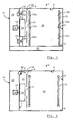
- An example in the Figures 1 and 2 illustrated cooking appliance 1 comprises an interior defined by a rear wall 2, a ceiling 3, a bottom surface 4, a first side wall 5, a front wall 6, a second side wall 7 and a side wall portion 8, the rear wall 2 and the front wall 6 also referred to as side walls can be.
- the interior is at least partially divided by a flow baffle 9 in a cooking chamber 10 and a pressure chamber 11.
- a flow baffle 9 in a cooking chamber 10 and a pressure chamber 11.
- the front wall 6 is a door not shown for loading the cooking chamber 10 with food (not shown) and for removing the same.
- a frame 12 with a plurality of rails 13a-f for insertion of food supports (not shown), on which the food is placed, provided.
- a radial fan 14 which is driven by a motor 16 via a shaft 15.
- the radial fan 14 sucks atmosphere (steam, vapor, air etc.) from the cooking chamber 10 through an opening located in the center of the Strömungsleitblechs 9 17 and blows it off radially.
- atmosphere steam, vapor, air etc.
- the atmosphere is due to this pressure difference through slots 18 between the edge of Strömungsleitblechs 9 and at least one of the rear wall 2, front wall 6, ceiling 3 and bottom surface 4 again led into the cooking chamber 10 ,
- slots 18 it is also possible to provide openings in the flow guide plate 9 in the edge area of the flow guide plate 9.
- the illustrated cooking appliance 1 comprises a microwave heating and another, not shown, means for the treatment of food in the cooking chamber 10, such as a ventilation device, an electric heater, a gas-powered heater, a heat exchange device, a cooling device, a moisture supply device and / or a mecanicsabloom surprise.
- a moisture baffle is preferably located in a floor area 19.
- a moisture supply device may include a steam injector that injects steam into the flow.
- each treatment device At least the regulation or control and the electrical connections of each treatment device are located, as well as the motor 16, in an installation space 20 adjacent to the pressure space 11.
- the installation space 20 is directly via a door (not shown) in an outer side wall 21 accessible from outside the cooking appliance 1 to facilitate maintenance and installation.
- Microwaves are generated in magnetrons 22, 23 of the microwave heating.
- the microwaves generated in the magnetrons 22, 23 are guided to a respective gate 24, 25 in order to be radiated on a direct path into the pressure chamber 11.
- the pressure chamber 11 and the cooking chamber 10 form coupled, substantially cuboid resonators for the radiated microwaves. For this reason, finds a uniform microwave energy distribution in the cooking chamber 10 instead.
- the coupling takes place essentially via the slots 18, which are also provided for circulating the cooking chamber atmosphere.
- openings (not shown) for microwave-permeable openings may be provided in the flow guide plate 9. In order to maintain the pressure difference between the pressure chamber 11 and the cooking chamber 10, these openings are not permeable to air, but filled with dielectric material, for example, quartz glass, borosilicate glass or ceramic.
- the radial fan 14 is at least partially made of a material that reflects microwaves.
- the gates 24,25 are located in the side wall portion 8, which adjacent to the second side wall 7 through which the drive shaft 15 of the radial fan 14 projects, is arranged.
- the radial fan 14 extends in the radial direction at most to the transition from the side wall 7 to the side wall portion 8, so that the gates 24,25 are not shielded by the fan 14.
- rod or slot antennas are provided for the radiation in the pressure chamber 11 rod or slot antennas are provided.
- the radiation characteristic is such that at least one radiation takes place parallel to the side wall part 8.
- the radiated so microwaves therefore reach the radial fan 14 and are swirled by him.
- the side wall portion 8 is at an angle to the side wall 7. Due to this arrangement, the microwaves are already partly reflected into the cooking chamber 10 via the rear wall 2.
- a further homogenization of the microwave energy distribution is achieved in that the gates 24,25 are provided at different heights in the interior of the cooking appliance 1.
- the cooking appliance 1 is designed for large kitchen use, commercially available magnetrons 22, 23, which are designed for use in household microwave appliances, are used for cost reasons. These usually have a nominal power of about 2000 watts of HF.
- the number of magnetrons 22,23 depends on the number of rails 13a-f in the frame 12, that is on the number and dimensions of the accommodatable food supports.
- the first magnetron 22 includes a housing 26 from which an antenna stub 27 protrudes.
- the antenna stub 27 also includes a protective cap 28.
- the magnetron 22 includes a cathode 29 which is heated during operation.
- the cathode 29 is surrounded by an anode 30 with projecting, circumferentially arranged wings 31.
- the magnetron also contains a magnet stack 32.
- the electrons emitted by the cathode 29 are guided around the cathode 29 under the influence of the electric and magnetic fields. The reaction of the fields on the incident on the anode 30 electrons creates an oscillation.
- An inner conductor 33 of the antenna couples the generated microwaves out of the oscillator device and radiates them into the pressure chamber 11.
- the microwaves generated in the magnetron 22 are thus emitted directly into the pressure chamber 11 without the interposition of a waveguide.
- some magnetrons instead of the inner conductor 33 may comprise a waveguide for coupling out the microwaves.
- a cooking appliance 1 for the commercial kitchen use differs from a household microwave.
- the moisture in the cooking chamber 10 and in the pressure chamber 11 can be high and the temperature there can reach values of approximately 400 ° C.
- the magnetrons 22,23 should be protected from this atmosphere.
- a cover in the form of a hood 34 is used for such a protection.
- the hood 34 is made of a dielectric material which is permeable to microwaves. The material also has a low thermal conductivity.
- a hood 34 made of ceramic can be used. Due to the low dielectric constant, glass, for example quartz or borosilicate glass (Pyrex), is also suitable as a manufacturing material.
- the hood 34 surrounds the protruding through the side wall portion 8 antenna stub 27 of the magnetron. To increase the thermal insulation is a gap 35 between the inside of the hood 34 and the antenna stub 37. The gap 35 is in particular filled with air.
- the hood 34 is fastened in the illustrated embodiment via a flange 36 to the side wall part 8.
- the hood 34 fulfills the dual function of the gas-tight sealing of the installation space 20 with respect to the interior atmosphere as well as the thermal insulation of the magnetron antenna stub 27.
- the flange also comprises two flat gaskets 37,38, a stainless steel rotary member 39 and screws 40,41 for fixing the stainless steel rotary member 39 at the cooking chamber side of the side wall part. 8
- the direct magnetron coupling has the advantage that the usual in professional Mikrowellengaréen Modenmischerboxen and paddle wheels outside the Garausninnenraums omitted. This also applies to the necessary for the protection of the magnetron from mismatch waveguides, circulators and directional couplers, which are commonly used. Thus, both costs and space in the installation room 20 are saved.
Landscapes
- Physics & Mathematics (AREA)
- Electromagnetism (AREA)
- Constitution Of High-Frequency Heating (AREA)
- Electric Ovens (AREA)
Priority Applications (1)
| Application Number | Priority Date | Filing Date | Title |
|---|---|---|---|
| EP20080291071 EP2187704B1 (fr) | 2008-11-17 | 2008-11-17 | Appareil de cuisson et procédé de rayonnement de micro-ondes dans la chambre interne d'un appareil de cuisson |
Applications Claiming Priority (1)
| Application Number | Priority Date | Filing Date | Title |
|---|---|---|---|
| EP20080291071 EP2187704B1 (fr) | 2008-11-17 | 2008-11-17 | Appareil de cuisson et procédé de rayonnement de micro-ondes dans la chambre interne d'un appareil de cuisson |
Publications (2)
| Publication Number | Publication Date |
|---|---|
| EP2187704A1 true EP2187704A1 (fr) | 2010-05-19 |
| EP2187704B1 EP2187704B1 (fr) | 2012-06-06 |
Family
ID=40589392
Family Applications (1)
| Application Number | Title | Priority Date | Filing Date |
|---|---|---|---|
| EP20080291071 Active EP2187704B1 (fr) | 2008-11-17 | 2008-11-17 | Appareil de cuisson et procédé de rayonnement de micro-ondes dans la chambre interne d'un appareil de cuisson |
Country Status (1)
| Country | Link |
|---|---|
| EP (1) | EP2187704B1 (fr) |
Cited By (1)
| Publication number | Priority date | Publication date | Assignee | Title |
|---|---|---|---|---|
| DE102017127172A1 (de) | 2017-11-17 | 2019-05-23 | Fricke Und Mallah Microwave Technology Gmbh | Erhitzungshomogener Kombigarofen |
Citations (4)
| Publication number | Priority date | Publication date | Assignee | Title |
|---|---|---|---|---|
| US3532847A (en) * | 1965-06-05 | 1970-10-06 | Herbert August Puschner | Device for heating non-metallic material |
| US4866233A (en) * | 1983-08-10 | 1989-09-12 | Snowdrift Corporation N.V. | System for heating objects with microwaves |
| EP0429822A1 (fr) | 1989-11-29 | 1991-06-05 | ZANUSSI GRANDI IMPIANTI S.p.A. | Four combiné à micro-ondes et a convection forcée |
| US5237141A (en) | 1990-07-17 | 1993-08-17 | Matsushita Electric Industrial Co., Ltd. | High frequency heating apparatus and electromagnetic wave detector for use in high frequency heating apparatus |
-
2008
- 2008-11-17 EP EP20080291071 patent/EP2187704B1/fr active Active
Patent Citations (4)
| Publication number | Priority date | Publication date | Assignee | Title |
|---|---|---|---|---|
| US3532847A (en) * | 1965-06-05 | 1970-10-06 | Herbert August Puschner | Device for heating non-metallic material |
| US4866233A (en) * | 1983-08-10 | 1989-09-12 | Snowdrift Corporation N.V. | System for heating objects with microwaves |
| EP0429822A1 (fr) | 1989-11-29 | 1991-06-05 | ZANUSSI GRANDI IMPIANTI S.p.A. | Four combiné à micro-ondes et a convection forcée |
| US5237141A (en) | 1990-07-17 | 1993-08-17 | Matsushita Electric Industrial Co., Ltd. | High frequency heating apparatus and electromagnetic wave detector for use in high frequency heating apparatus |
Cited By (1)
| Publication number | Priority date | Publication date | Assignee | Title |
|---|---|---|---|---|
| DE102017127172A1 (de) | 2017-11-17 | 2019-05-23 | Fricke Und Mallah Microwave Technology Gmbh | Erhitzungshomogener Kombigarofen |
Also Published As
| Publication number | Publication date |
|---|---|
| EP2187704B1 (fr) | 2012-06-06 |
Similar Documents
| Publication | Publication Date | Title |
|---|---|---|
| DE60308134T2 (de) | Wandmontierter Mikrowellenherd | |
| CN1159545C (zh) | 微波炉中的通风管 | |
| EP3035773B2 (fr) | Generateur de micro-ondes et four a micro-ondes | |
| DE68921050T2 (de) | Mikrowellenheizgerät. | |
| EP1816402B1 (fr) | Four | |
| CH656283A5 (de) | Mikrowellenofen. | |
| DE2921995A1 (de) | Mikrowellenheizeinrichtung | |
| EP2187700B1 (fr) | Appareil de cuisson et procédé d'alimentation en micro-ondes dans la chambre interne d'un appareil de cuisson | |
| DE7739400U1 (de) | Einrichtung zur erhitzung von substanzen mit mikrowellenenergie | |
| EP2187704B1 (fr) | Appareil de cuisson et procédé de rayonnement de micro-ondes dans la chambre interne d'un appareil de cuisson | |
| EP3897074A1 (fr) | Module de chauffage à ondes à haute fréquence | |
| CH637794A5 (en) | Microwave oven | |
| EP2187702A1 (fr) | Appareil de cuisson doté d'un chauffage à micro-ondes | |
| EP2187699B1 (fr) | Appareil de cuisson et son procédé d'alimentation en micro-ondes au sein de l'enceinte de l'appareil de cuisson. | |
| CN106231711A (zh) | 微波炉的天线组件及微波炉 | |
| EP0049817B1 (fr) | Appareil de chauffage à micro-ondes ayant un dispositif d'étanchéité à la porte servant à éviter la fuite de micro-ondes | |
| EP3643141B1 (fr) | Appareil de cuisson à micro-ondes à antenne planaire | |
| EP0003764B1 (fr) | Four de cuisson double, en particulier four de cuisson encastré | |
| DE102006002263A1 (de) | Backofen | |
| DE2921990B2 (de) | Mikrowellenofen | |
| DE1565845B2 (de) | Mikrowellenherd | |
| DE3242638A1 (de) | Wellenleiter fuer hochfrequenzuebertragung | |
| DE7833977U1 (de) | Herd oder ofen fuer verbundbetrieb mit mikrowellenenergie und widerstandsheizung | |
| EP2187703A1 (fr) | Appareil de cuisson doté d'une alimentation à micro-ondes | |
| DE2921994C2 (de) | Mikrowellenofen |
Legal Events
| Date | Code | Title | Description |
|---|---|---|---|
| PUAI | Public reference made under article 153(3) epc to a published international application that has entered the european phase |
Free format text: ORIGINAL CODE: 0009012 |
|
| AK | Designated contracting states |
Kind code of ref document: A1 Designated state(s): AT BE BG CH CY CZ DE DK EE ES FI FR GB GR HR HU IE IS IT LI LT LU LV MC MT NL NO PL PT RO SE SI SK TR |
|
| AX | Request for extension of the european patent |
Extension state: AL BA MK RS |
|
| 17P | Request for examination filed |
Effective date: 20101112 |
|
| AKX | Designation fees paid |
Designated state(s): AT BE BG CH CY CZ DE DK EE ES FI FR GB GR HR HU IE IS IT LI LT LU LV MC MT NL NO PL PT RO SE SI SK TR |
|
| GRAP | Despatch of communication of intention to grant a patent |
Free format text: ORIGINAL CODE: EPIDOSNIGR1 |
|
| GRAS | Grant fee paid |
Free format text: ORIGINAL CODE: EPIDOSNIGR3 |
|
| GRAA | (expected) grant |
Free format text: ORIGINAL CODE: 0009210 |
|
| AK | Designated contracting states |
Kind code of ref document: B1 Designated state(s): AT BE BG CH CY CZ DE DK EE ES FI FR GB GR HR HU IE IS IT LI LT LU LV MC MT NL NO PL PT RO SE SI SK TR |
|
| REG | Reference to a national code |
Ref country code: GB Ref legal event code: FG4D Free format text: NOT ENGLISH |
|
| REG | Reference to a national code |
Ref country code: AT Ref legal event code: REF Ref document number: 561538 Country of ref document: AT Kind code of ref document: T Effective date: 20120615 Ref country code: CH Ref legal event code: EP |
|
| REG | Reference to a national code |
Ref country code: IE Ref legal event code: FG4D Free format text: LANGUAGE OF EP DOCUMENT: GERMAN |
|
| REG | Reference to a national code |
Ref country code: DE Ref legal event code: R096 Ref document number: 502008007374 Country of ref document: DE Effective date: 20120802 |
|
| REG | Reference to a national code |
Ref country code: NL Ref legal event code: VDEP Effective date: 20120606 |
|
| PG25 | Lapsed in a contracting state [announced via postgrant information from national office to epo] |
Ref country code: LT Free format text: LAPSE BECAUSE OF FAILURE TO SUBMIT A TRANSLATION OF THE DESCRIPTION OR TO PAY THE FEE WITHIN THE PRESCRIBED TIME-LIMIT Effective date: 20120606 Ref country code: SE Free format text: LAPSE BECAUSE OF FAILURE TO SUBMIT A TRANSLATION OF THE DESCRIPTION OR TO PAY THE FEE WITHIN THE PRESCRIBED TIME-LIMIT Effective date: 20120606 Ref country code: FI Free format text: LAPSE BECAUSE OF FAILURE TO SUBMIT A TRANSLATION OF THE DESCRIPTION OR TO PAY THE FEE WITHIN THE PRESCRIBED TIME-LIMIT Effective date: 20120606 Ref country code: NO Free format text: LAPSE BECAUSE OF FAILURE TO SUBMIT A TRANSLATION OF THE DESCRIPTION OR TO PAY THE FEE WITHIN THE PRESCRIBED TIME-LIMIT Effective date: 20120906 Ref country code: CY Free format text: LAPSE BECAUSE OF FAILURE TO SUBMIT A TRANSLATION OF THE DESCRIPTION OR TO PAY THE FEE WITHIN THE PRESCRIBED TIME-LIMIT Effective date: 20120606 |
|
| REG | Reference to a national code |
Ref country code: LT Ref legal event code: MG4D Effective date: 20120606 |
|
| PG25 | Lapsed in a contracting state [announced via postgrant information from national office to epo] |
Ref country code: SI Free format text: LAPSE BECAUSE OF FAILURE TO SUBMIT A TRANSLATION OF THE DESCRIPTION OR TO PAY THE FEE WITHIN THE PRESCRIBED TIME-LIMIT Effective date: 20120606 Ref country code: HR Free format text: LAPSE BECAUSE OF FAILURE TO SUBMIT A TRANSLATION OF THE DESCRIPTION OR TO PAY THE FEE WITHIN THE PRESCRIBED TIME-LIMIT Effective date: 20120606 Ref country code: LV Free format text: LAPSE BECAUSE OF FAILURE TO SUBMIT A TRANSLATION OF THE DESCRIPTION OR TO PAY THE FEE WITHIN THE PRESCRIBED TIME-LIMIT Effective date: 20120606 |
|
| PG25 | Lapsed in a contracting state [announced via postgrant information from national office to epo] |
Ref country code: CZ Free format text: LAPSE BECAUSE OF FAILURE TO SUBMIT A TRANSLATION OF THE DESCRIPTION OR TO PAY THE FEE WITHIN THE PRESCRIBED TIME-LIMIT Effective date: 20120606 Ref country code: IS Free format text: LAPSE BECAUSE OF FAILURE TO SUBMIT A TRANSLATION OF THE DESCRIPTION OR TO PAY THE FEE WITHIN THE PRESCRIBED TIME-LIMIT Effective date: 20121006 Ref country code: SK Free format text: LAPSE BECAUSE OF FAILURE TO SUBMIT A TRANSLATION OF THE DESCRIPTION OR TO PAY THE FEE WITHIN THE PRESCRIBED TIME-LIMIT Effective date: 20120606 Ref country code: EE Free format text: LAPSE BECAUSE OF FAILURE TO SUBMIT A TRANSLATION OF THE DESCRIPTION OR TO PAY THE FEE WITHIN THE PRESCRIBED TIME-LIMIT Effective date: 20120606 Ref country code: RO Free format text: LAPSE BECAUSE OF FAILURE TO SUBMIT A TRANSLATION OF THE DESCRIPTION OR TO PAY THE FEE WITHIN THE PRESCRIBED TIME-LIMIT Effective date: 20120606 Ref country code: NL Free format text: LAPSE BECAUSE OF FAILURE TO SUBMIT A TRANSLATION OF THE DESCRIPTION OR TO PAY THE FEE WITHIN THE PRESCRIBED TIME-LIMIT Effective date: 20120606 |
|
| PG25 | Lapsed in a contracting state [announced via postgrant information from national office to epo] |
Ref country code: PT Free format text: LAPSE BECAUSE OF FAILURE TO SUBMIT A TRANSLATION OF THE DESCRIPTION OR TO PAY THE FEE WITHIN THE PRESCRIBED TIME-LIMIT Effective date: 20121008 Ref country code: PL Free format text: LAPSE BECAUSE OF FAILURE TO SUBMIT A TRANSLATION OF THE DESCRIPTION OR TO PAY THE FEE WITHIN THE PRESCRIBED TIME-LIMIT Effective date: 20120606 |
|
| PLBE | No opposition filed within time limit |
Free format text: ORIGINAL CODE: 0009261 |
|
| STAA | Information on the status of an ep patent application or granted ep patent |
Free format text: STATUS: NO OPPOSITION FILED WITHIN TIME LIMIT |
|
| PG25 | Lapsed in a contracting state [announced via postgrant information from national office to epo] |
Ref country code: ES Free format text: LAPSE BECAUSE OF FAILURE TO SUBMIT A TRANSLATION OF THE DESCRIPTION OR TO PAY THE FEE WITHIN THE PRESCRIBED TIME-LIMIT Effective date: 20120917 Ref country code: DK Free format text: LAPSE BECAUSE OF FAILURE TO SUBMIT A TRANSLATION OF THE DESCRIPTION OR TO PAY THE FEE WITHIN THE PRESCRIBED TIME-LIMIT Effective date: 20120606 |
|
| 26N | No opposition filed |
Effective date: 20130307 |
|
| BERE | Be: lapsed |
Owner name: TOPINOX SARL Effective date: 20121130 |
|
| REG | Reference to a national code |
Ref country code: CH Ref legal event code: PL |
|
| REG | Reference to a national code |
Ref country code: DE Ref legal event code: R097 Ref document number: 502008007374 Country of ref document: DE Effective date: 20130307 |
|
| PG25 | Lapsed in a contracting state [announced via postgrant information from national office to epo] |
Ref country code: CH Free format text: LAPSE BECAUSE OF NON-PAYMENT OF DUE FEES Effective date: 20121130 Ref country code: BG Free format text: LAPSE BECAUSE OF FAILURE TO SUBMIT A TRANSLATION OF THE DESCRIPTION OR TO PAY THE FEE WITHIN THE PRESCRIBED TIME-LIMIT Effective date: 20120906 Ref country code: LI Free format text: LAPSE BECAUSE OF NON-PAYMENT OF DUE FEES Effective date: 20121130 |
|
| REG | Reference to a national code |
Ref country code: IE Ref legal event code: MM4A |
|
| PG25 | Lapsed in a contracting state [announced via postgrant information from national office to epo] |
Ref country code: BE Free format text: LAPSE BECAUSE OF NON-PAYMENT OF DUE FEES Effective date: 20121130 |
|
| PG25 | Lapsed in a contracting state [announced via postgrant information from national office to epo] |
Ref country code: IE Free format text: LAPSE BECAUSE OF NON-PAYMENT OF DUE FEES Effective date: 20121117 |
|
| PG25 | Lapsed in a contracting state [announced via postgrant information from national office to epo] |
Ref country code: MT Free format text: LAPSE BECAUSE OF FAILURE TO SUBMIT A TRANSLATION OF THE DESCRIPTION OR TO PAY THE FEE WITHIN THE PRESCRIBED TIME-LIMIT Effective date: 20120606 |
|
| PG25 | Lapsed in a contracting state [announced via postgrant information from national office to epo] |
Ref country code: MC Free format text: LAPSE BECAUSE OF NON-PAYMENT OF DUE FEES Effective date: 20121130 Ref country code: TR Free format text: LAPSE BECAUSE OF FAILURE TO SUBMIT A TRANSLATION OF THE DESCRIPTION OR TO PAY THE FEE WITHIN THE PRESCRIBED TIME-LIMIT Effective date: 20120606 |
|
| PG25 | Lapsed in a contracting state [announced via postgrant information from national office to epo] |
Ref country code: LU Free format text: LAPSE BECAUSE OF NON-PAYMENT OF DUE FEES Effective date: 20121117 |
|
| PG25 | Lapsed in a contracting state [announced via postgrant information from national office to epo] |
Ref country code: HU Free format text: LAPSE BECAUSE OF FAILURE TO SUBMIT A TRANSLATION OF THE DESCRIPTION OR TO PAY THE FEE WITHIN THE PRESCRIBED TIME-LIMIT Effective date: 20081117 |
|
| PG25 | Lapsed in a contracting state [announced via postgrant information from national office to epo] |
Ref country code: GR Free format text: LAPSE BECAUSE OF FAILURE TO SUBMIT A TRANSLATION OF THE DESCRIPTION OR TO PAY THE FEE WITHIN THE PRESCRIBED TIME-LIMIT Effective date: 20120606 |
|
| REG | Reference to a national code |
Ref country code: AT Ref legal event code: MM01 Ref document number: 561538 Country of ref document: AT Kind code of ref document: T Effective date: 20131117 |
|
| PG25 | Lapsed in a contracting state [announced via postgrant information from national office to epo] |
Ref country code: AT Free format text: LAPSE BECAUSE OF NON-PAYMENT OF DUE FEES Effective date: 20131117 |
|
| REG | Reference to a national code |
Ref country code: FR Ref legal event code: PLFP Year of fee payment: 8 |
|
| REG | Reference to a national code |
Ref country code: FR Ref legal event code: PLFP Year of fee payment: 9 |
|
| REG | Reference to a national code |
Ref country code: FR Ref legal event code: PLFP Year of fee payment: 10 |
|
| PGFP | Annual fee paid to national office [announced via postgrant information from national office to epo] |
Ref country code: IT Payment date: 20191120 Year of fee payment: 12 |
|
| PG25 | Lapsed in a contracting state [announced via postgrant information from national office to epo] |
Ref country code: IT Free format text: LAPSE BECAUSE OF NON-PAYMENT OF DUE FEES Effective date: 20201117 |
|
| P01 | Opt-out of the competence of the unified patent court (upc) registered |
Effective date: 20230619 |
|
| PGFP | Annual fee paid to national office [announced via postgrant information from national office to epo] |
Ref country code: GB Payment date: 20231123 Year of fee payment: 16 |
|
| PGFP | Annual fee paid to national office [announced via postgrant information from national office to epo] |
Ref country code: FR Payment date: 20231123 Year of fee payment: 16 Ref country code: DE Payment date: 20231120 Year of fee payment: 16 |