EP2185856B1 - Beleuchtungseinrichtung mit mehreren steuerbaren leuchtdioden - Google Patents
Beleuchtungseinrichtung mit mehreren steuerbaren leuchtdioden Download PDFInfo
- Publication number
- EP2185856B1 EP2185856B1 EP08803116A EP08803116A EP2185856B1 EP 2185856 B1 EP2185856 B1 EP 2185856B1 EP 08803116 A EP08803116 A EP 08803116A EP 08803116 A EP08803116 A EP 08803116A EP 2185856 B1 EP2185856 B1 EP 2185856B1
- Authority
- EP
- European Patent Office
- Prior art keywords
- light
- module
- leds
- lighting
- lighting device
- Prior art date
- Legal status (The legal status is an assumption and is not a legal conclusion. Google has not performed a legal analysis and makes no representation as to the accuracy of the status listed.)
- Active
Links
Images


Classifications
-
- F—MECHANICAL ENGINEERING; LIGHTING; HEATING; WEAPONS; BLASTING
- F21—LIGHTING
- F21K—NON-ELECTRIC LIGHT SOURCES USING LUMINESCENCE; LIGHT SOURCES USING ELECTROCHEMILUMINESCENCE; LIGHT SOURCES USING CHARGES OF COMBUSTIBLE MATERIAL; LIGHT SOURCES USING SEMICONDUCTOR DEVICES AS LIGHT-GENERATING ELEMENTS; LIGHT SOURCES NOT OTHERWISE PROVIDED FOR
- F21K9/00—Light sources using semiconductor devices as light-generating elements, e.g. using light-emitting diodes [LED] or lasers
-
- F—MECHANICAL ENGINEERING; LIGHTING; HEATING; WEAPONS; BLASTING
- F21—LIGHTING
- F21V—FUNCTIONAL FEATURES OR DETAILS OF LIGHTING DEVICES OR SYSTEMS THEREOF; STRUCTURAL COMBINATIONS OF LIGHTING DEVICES WITH OTHER ARTICLES, NOT OTHERWISE PROVIDED FOR
- F21V23/00—Arrangement of electric circuit elements in or on lighting devices
- F21V23/003—Arrangement of electric circuit elements in or on lighting devices the elements being electronics drivers or controllers for operating the light source, e.g. for a LED array
- F21V23/004—Arrangement of electric circuit elements in or on lighting devices the elements being electronics drivers or controllers for operating the light source, e.g. for a LED array arranged on a substrate, e.g. a printed circuit board
- F21V23/005—Arrangement of electric circuit elements in or on lighting devices the elements being electronics drivers or controllers for operating the light source, e.g. for a LED array arranged on a substrate, e.g. a printed circuit board the substrate is supporting also the light source
-
- F—MECHANICAL ENGINEERING; LIGHTING; HEATING; WEAPONS; BLASTING
- F21—LIGHTING
- F21V—FUNCTIONAL FEATURES OR DETAILS OF LIGHTING DEVICES OR SYSTEMS THEREOF; STRUCTURAL COMBINATIONS OF LIGHTING DEVICES WITH OTHER ARTICLES, NOT OTHERWISE PROVIDED FOR
- F21V31/00—Gas-tight or water-tight arrangements
- F21V31/04—Provision of filling media
-
- H—ELECTRICITY
- H05—ELECTRIC TECHNIQUES NOT OTHERWISE PROVIDED FOR
- H05B—ELECTRIC HEATING; ELECTRIC LIGHT SOURCES NOT OTHERWISE PROVIDED FOR; CIRCUIT ARRANGEMENTS FOR ELECTRIC LIGHT SOURCES, IN GENERAL
- H05B45/00—Circuit arrangements for operating light-emitting diodes [LED]
- H05B45/20—Controlling the colour of the light
- H05B45/22—Controlling the colour of the light using optical feedback
-
- H—ELECTRICITY
- H05—ELECTRIC TECHNIQUES NOT OTHERWISE PROVIDED FOR
- H05B—ELECTRIC HEATING; ELECTRIC LIGHT SOURCES NOT OTHERWISE PROVIDED FOR; CIRCUIT ARRANGEMENTS FOR ELECTRIC LIGHT SOURCES, IN GENERAL
- H05B45/00—Circuit arrangements for operating light-emitting diodes [LED]
- H05B45/20—Controlling the colour of the light
- H05B45/28—Controlling the colour of the light using temperature feedback
-
- H—ELECTRICITY
- H05—ELECTRIC TECHNIQUES NOT OTHERWISE PROVIDED FOR
- H05B—ELECTRIC HEATING; ELECTRIC LIGHT SOURCES NOT OTHERWISE PROVIDED FOR; CIRCUIT ARRANGEMENTS FOR ELECTRIC LIGHT SOURCES, IN GENERAL
- H05B45/00—Circuit arrangements for operating light-emitting diodes [LED]
- H05B45/40—Details of LED load circuits
-
- H—ELECTRICITY
- H05—ELECTRIC TECHNIQUES NOT OTHERWISE PROVIDED FOR
- H05K—PRINTED CIRCUITS; CASINGS OR CONSTRUCTIONAL DETAILS OF ELECTRIC APPARATUS; MANUFACTURE OF ASSEMBLAGES OF ELECTRICAL COMPONENTS
- H05K1/00—Printed circuits
- H05K1/02—Details
- H05K1/14—Structural association of two or more printed circuits
- H05K1/141—One or more single auxiliary printed circuits mounted on a main printed circuit, e.g. modules, adapters
-
- H—ELECTRICITY
- H05—ELECTRIC TECHNIQUES NOT OTHERWISE PROVIDED FOR
- H05K—PRINTED CIRCUITS; CASINGS OR CONSTRUCTIONAL DETAILS OF ELECTRIC APPARATUS; MANUFACTURE OF ASSEMBLAGES OF ELECTRICAL COMPONENTS
- H05K1/00—Printed circuits
- H05K1/18—Printed circuits structurally associated with non-printed electric components
- H05K1/181—Printed circuits structurally associated with non-printed electric components associated with surface mounted components
-
- F—MECHANICAL ENGINEERING; LIGHTING; HEATING; WEAPONS; BLASTING
- F21—LIGHTING
- F21V—FUNCTIONAL FEATURES OR DETAILS OF LIGHTING DEVICES OR SYSTEMS THEREOF; STRUCTURAL COMBINATIONS OF LIGHTING DEVICES WITH OTHER ARTICLES, NOT OTHERWISE PROVIDED FOR
- F21V23/00—Arrangement of electric circuit elements in or on lighting devices
- F21V23/04—Arrangement of electric circuit elements in or on lighting devices the elements being switches
- F21V23/0442—Arrangement of electric circuit elements in or on lighting devices the elements being switches activated by means of a sensor, e.g. motion or photodetectors
-
- F—MECHANICAL ENGINEERING; LIGHTING; HEATING; WEAPONS; BLASTING
- F21—LIGHTING
- F21Y—INDEXING SCHEME ASSOCIATED WITH SUBCLASSES F21K, F21L, F21S and F21V, RELATING TO THE FORM OR THE KIND OF THE LIGHT SOURCES OR OF THE COLOUR OF THE LIGHT EMITTED
- F21Y2113/00—Combination of light sources
- F21Y2113/10—Combination of light sources of different colours
- F21Y2113/13—Combination of light sources of different colours comprising an assembly of point-like light sources
-
- F—MECHANICAL ENGINEERING; LIGHTING; HEATING; WEAPONS; BLASTING
- F21—LIGHTING
- F21Y—INDEXING SCHEME ASSOCIATED WITH SUBCLASSES F21K, F21L, F21S and F21V, RELATING TO THE FORM OR THE KIND OF THE LIGHT SOURCES OR OF THE COLOUR OF THE LIGHT EMITTED
- F21Y2115/00—Light-generating elements of semiconductor light sources
-
- H—ELECTRICITY
- H05—ELECTRIC TECHNIQUES NOT OTHERWISE PROVIDED FOR
- H05B—ELECTRIC HEATING; ELECTRIC LIGHT SOURCES NOT OTHERWISE PROVIDED FOR; CIRCUIT ARRANGEMENTS FOR ELECTRIC LIGHT SOURCES, IN GENERAL
- H05B45/00—Circuit arrangements for operating light-emitting diodes [LED]
- H05B45/30—Driver circuits
- H05B45/32—Pulse-control circuits
- H05B45/325—Pulse-width modulation [PWM]
-
- H—ELECTRICITY
- H05—ELECTRIC TECHNIQUES NOT OTHERWISE PROVIDED FOR
- H05K—PRINTED CIRCUITS; CASINGS OR CONSTRUCTIONAL DETAILS OF ELECTRIC APPARATUS; MANUFACTURE OF ASSEMBLAGES OF ELECTRICAL COMPONENTS
- H05K1/00—Printed circuits
- H05K1/02—Details
- H05K1/03—Use of materials for the substrate
- H05K1/0306—Inorganic insulating substrates, e.g. ceramic, glass
-
- H—ELECTRICITY
- H05—ELECTRIC TECHNIQUES NOT OTHERWISE PROVIDED FOR
- H05K—PRINTED CIRCUITS; CASINGS OR CONSTRUCTIONAL DETAILS OF ELECTRIC APPARATUS; MANUFACTURE OF ASSEMBLAGES OF ELECTRICAL COMPONENTS
- H05K1/00—Printed circuits
- H05K1/02—Details
- H05K1/03—Use of materials for the substrate
- H05K1/05—Insulated conductive substrates, e.g. insulated metal substrate
-
- H—ELECTRICITY
- H05—ELECTRIC TECHNIQUES NOT OTHERWISE PROVIDED FOR
- H05K—PRINTED CIRCUITS; CASINGS OR CONSTRUCTIONAL DETAILS OF ELECTRIC APPARATUS; MANUFACTURE OF ASSEMBLAGES OF ELECTRICAL COMPONENTS
- H05K2201/00—Indexing scheme relating to printed circuits covered by H05K1/00
- H05K2201/10—Details of components or other objects attached to or integrated in a printed circuit board
- H05K2201/10007—Types of components
- H05K2201/10106—Light emitting diode [LED]
-
- Y—GENERAL TAGGING OF NEW TECHNOLOGICAL DEVELOPMENTS; GENERAL TAGGING OF CROSS-SECTIONAL TECHNOLOGIES SPANNING OVER SEVERAL SECTIONS OF THE IPC; TECHNICAL SUBJECTS COVERED BY FORMER USPC CROSS-REFERENCE ART COLLECTIONS [XRACs] AND DIGESTS
- Y02—TECHNOLOGIES OR APPLICATIONS FOR MITIGATION OR ADAPTATION AGAINST CLIMATE CHANGE
- Y02P—CLIMATE CHANGE MITIGATION TECHNOLOGIES IN THE PRODUCTION OR PROCESSING OF GOODS
- Y02P70/00—Climate change mitigation technologies in the production process for final industrial or consumer products
- Y02P70/50—Manufacturing or production processes characterised by the final manufactured product
Definitions
- the invention relates to a lighting device according to the preamble of claim 1.
- document DE 203 09 0 33U discloses a lighting module with all the features of a module of the lighting device, the preamble of claim 1.
- Light-emitting diodes, light-emitting diodes or LEDs designated light bulbs offer the possibility to produce flat and over the surface homogeneous light radiating headlamps in larger designs than surface lights with the names "Softlight”, "Filllight” or brighteners in all areas of professional lighting, can be used as portrait lights in the immediate vicinity of a motion picture or video camera, in confined spaces, such as vehicles and staircases, and for the construction of light walls in the event and stage lighting.
- a lighting device with a carrier is known, are provided on the connection points for contacting electronic components and printed conductors, which interconnect the connection points with each other and connect to a power source.
- a control electronics and switching devices for switching the light emitting diode are arranged on the support a light emitting diode.
- the light-emitting diode in particular emits white light and is mechanically on the support fixed and electrically contacted with connection points.
- the control electronics includes a light sensor for measuring the ambient brightness and controlling the brightness of the light emitting diode and has to control the intensity with which the light emitting diode, a pulse width modulation circuit.
- the known lighting device by the integration of a plurality of arranged on the support control electronics on a considerable amount of space, which would result in a compilation of a variety of lighting devices such as a headlight to considerable, in practice unacceptable dimensions and because of the large mutual distance of individual arranged on the support together with the control electronics and switching devices LEDs, the number of light-emitting elements would be too low for a headlight. Therefore, an application of the known illumination device is limited to interior lights of motor vehicles, light spots, reading lamps or the like.
- Lighting headlamps with light-emitting diodes or LEDs which are used for example as a camera attachment light for film and video cameras, have either the color temperature "daylight white” or “warm white”, with a stepless or exact switching on or switching from a warm white to a daylight white color temperature not possible and in both variants, the color reproduction in film and video recordings is unsatisfactory.
- LEDs of different colors with a non-continuous spectral pattern are used in an LED projector for the illumination of film or video recordings, the LEDs achieve the required values for color temperature and color reproduction, but still have incandescent or HMI lamps when used for filming or daylight on a significant color cast. In this case one speaks of an insufficient mixed light capability.
- a lighting device in which a plurality of LED chips, which emit monochromatic light of different color, in recesses a three-dimensional carrier used with rectangular cross-section, electrically connected to tracks and sealed with a transparent plastic.
- a diffuser plate of transparent plastic consisting of microlenses for light control is connected to the three-dimensional support.
- the overall characteristic of the light emitted by the illumination device is determined by the individual light modules arranged in the recesses of the three-dimensional support, that is to say when changing individual modules, the overall characteristic of the illumination device must be redetermined. Since the individual modules of the lighting device are assigned individual properties with regard to the color characteristic and light scattering, the overall characteristic of the light emitted by the lighting device can be considerably changed if individual modules fail.
- Object of the present invention is to provide a lighting device of the type mentioned above, which emits light with adjustable color, brightness and radiation characteristics, is compact, allows autonomous operation and can be configured with similar lighting devices and a lighting device, in particular a headlight or a surface light or light panel, with substantially homogeneous, controllable light output guaranteed.
- the solution according to the invention provides a lighting device which emits light with adjustable color, brightness and radiation characteristics, has a compact design, enables self-sufficient operation and can be configured as desired by its modularity with similar lighting devices, and an illumination device, in particular a headlight or a surface light or light panel, guaranteed with substantially homogeneous, controllable light output. This is done by selecting the light of different wavelength emitting LEDs and their arrangement as well Control an adjustable light mixture with optimal color space and, in the case of white light, with optimal color reproduction possible.
- the illumination device consists essentially of a light module in which both a light source with LEDs emitting several light of different wavelengths and a module electronics for driving the LEDs of the light source are integrated, wherein the module electronics and the LEDs are connected to a module carrier of the light module.
- optics for light mixing and / or beam shaping can be coupled to the lighting module.
- the module electronics is connected to a higher-level control or regulating device, a controllable and controllable light source for a lighting device can be produced, which can be connected to other optical devices for beam shaping.
- the light module can emit a light mixture whose parameters such as light color, color temperature and chromaticity in addition to the brightness of the emitted by the light module Light are adjustable.
- the modular design and the composition of the light module allows the formation of different types and sizes of lighting devices such as a headlight or a surface light.
- the module electronics equipped with a microcontroller make it possible to vary the control program for driving the LEDs or to connect the lighting module with a higher-level, external, i. to connect separate from the light module controller, so that the module electronics of the light module performs the entire control and possibly regulation of the self-sufficient light module and thus relieves the external controller.
- the module electronics preferably control the LEDs as a function of the temperature and / or the power of the lighting module and / or the brightness and / or the color of the light mixture emitted by the lighting module in such a way that the LEDs emitting light of different wavelengths combine the brightness, color and chromaticity of the light mixture is constant, which allows local temperature compensation and a self-sufficient light module without the need or use of an external control device.
- the brightness and the chromaticity of the light mixture emitted by the light module can be adjusted by the module electronics or calibrated via the module electronics.
- the possibility of precise calibration of the light module offers the advantage that the tolerances of the LEDs used can be compensated or a higher acceptance of the LED tolerances, without it becoming necessary to achieve the same behaving light modules, a very large number of LEDs. Obtain and maintain selections with tight tolerances.
- the LEDs arranged on the board of the light source with a small mutual distance and connected via arranged on the board traces and electrical connections of the light source to the module electronics, which can be connected via electrical connections of the light module to the external controller.
- the interface between the light source and the module electronics is designed so that as far as possible all connections of the LEDs used are led to the outside of the light source, where they are connected to a preferably the module carrier forming board of the module electronics become.
- This connection is via solder tails, which are arranged in a standardized grid and / or a connector in the manner of multi-pin headers or by a direct wire or bond connection.
- solder tails which are arranged in a standardized grid and / or a connector in the manner of multi-pin headers or by a direct wire or bond connection.
- the light source can be very small, and thus can be constructed inexpensively and with a high luminance.
- This configuration of the interfaces between the light source and the module electronics of the lighting module ensures that, for example, to provide lighting devices with different color characteristics, light sources with differently composed and formed LEDs can be connected to a standardized module electronics for driving the LEDs and a regulation of the lighting device emitted light mixture is made possible.
- the modular design and the autonomous operation of the lighting modules allows dynamic changes in color or brightness up to the complete switching on or off of certain areas of the luminous area or special effects, for example, for a portrait lighting by switching on a portion of the luminous area, the direction from which the Light is radiated, can be changed, or specifically color fringes are generated.
- This modular variability makes it possible, using similar lighting modules to produce both surface lights with large light-emitting surface and headlights, with which bundled or expanded light is emitted.
- By continuously changing the characteristics of the illumination device it is possible to vary between “spotlight” and “softlight”, for example by operating a few modules in the middle of the high-power lighting device (spotlight) or many low-power lighting modules (softlight).
- the radiating surfaces of the above-mentioned headlights need not be rectangular and planar, but a variety of possible shapes can be formed, which can be realized with the predominantly square lighting modules, such. Light strips and bars, L shapes, rings, etc. Even curved radiating surfaces, which are composed of a number of light modules, can be formed to achieve certain effects. Furthermore, so-called "LED snakes" in the form of movable chains can be formed, which allow any geometric shape of the juxtaposition such as zig-zag shapes, circular or elliptical shapes.
- the board carrying the LEDs of the light source consists of a board made of an electrically insulating, good heat conductive material, preferably of aluminum nitrite or one of a metal core board.
- the light source and the module electronics may be directly connected together, e.g. the light source is soldered or plugged directly onto the module electronics or via a recess in the module electronics. In this case, a flat, space-saving construction is achieved.
- the entire light module can then be e.g. be attached by screws to a larger heat sink or the headlight housing, it is thermally advantageous if the light generating unit is directly coupled to the larger heat sink.
- the module carrier can be formed plate-shaped, a recess for inserting the board formed as a board and / or the base of a module heatsink and for mounting the board and / or the module heatsink Attachment holders and connecting elements for connecting the module carrier with a motherboard.
- the board of the light source is connected to a module heat sink with good thermal conductivity and is preferably arranged on a base of the module heat sink that is elevated relative to a surface of the module heat sink, so that the Board is arranged elevated relative to the surface of the module carrier, while the socket receiving surface of the module heat sink fastening elements for connecting the module heat sink with the module carrier.
- the light source and the module electronics may be mounted on a common carrier component, e.g. be attached to the module heat sink.
- a common carrier component e.g. be attached to the module heat sink.
- This embodiment provides the same good heat dissipation advantages that a safe and simple mechanical connection between the entire light module and a headlight housing or a cooling device on standard fasteners such as screws, pins u. ⁇ . Can be produced and that the board or the module carrier of the module electronics is not mechanically stressed.
- the module heat sink is preferably made of a very good thermal conductivity material such. Copper or aluminum.
- the light generating unit is mounted elevated relative to the module electronics, so that fasteners, such as e.g. Screws or notched nails, and electronic components can also be accommodated on the top of the module electronics, without disturbing the beam path of the LEDs.
- fasteners such as e.g. Screws or notched nails
- electronic components can also be accommodated on the top of the module electronics, without disturbing the beam path of the LEDs.
- a downstream optics can catch in this way all the light rays that are emitted into the half-space and thus be made very effective.
- the module carrier is in particular plate-shaped, so that it simultaneously forms the board of the module electronics.
- it has an outline for a substantially continuous juxtaposition of a plurality of identically designed module carriers and thus lighting modules for a light-emitting surface of a lighting device.
- the module carriers of several lighting modules can be used in recordings of a motherboard containing an external controller.
- the driver circuits are each connected to a pulse width modulated control signals emitting output of the microcontroller and acted upon by a supply voltage.
- the module electronics is supplied with one or more operating voltages and generates, stabilizes and limits the required LED currents themselves.
- the driver circuits have a temperature-compensated constant current source which is connected to a supply voltage associated with the driver circuit and drives an electronic switch connected in series with the LEDs fed by the respective driver circuit in such a way that the LEDs are supplied with constant current.
- a digital, serial interface to the microcontroller essentially allows the control of the color channels, the calibration, the retrieval of status information from the light module, such as the board temperature, and the overloading of the operating program (download).
- the interface to the light module is preferably networkable and designed in the manner of an industrial field bus, so that a larger number of light modules can be operated on a bus.
- the module electronics when connecting a plurality of identically constructed lighting modules of a lighting device, is able to exchange data via a serial interface with an external controller and to control the LEDs via preferably pulse width modulated signals for stepless control of the LEDs.
- the master module or the external controller carries out a periodic query of all board temperatures of the lighting module and outputs a signal representing the highest detected temperature to all lighting modules, which after a synchronization command, a brightness adjustment on the basis of perform the highest detected temperature representing signal.
- composition of the light generating unit of light of different wavelength emitting LEDs can be adjusted without hardware change solely by the control of the LEDs by means of the module electronics, a desired light mixture and optionally compensated or regulated autonomously using a brightness and / or color sensor.
- the LEDs are formed as LED chips, which are contacted in chip-on-board technology with the conductor tracks of the board, preferably by bonding, flip-chip contacting or Leitklebung electrically.
- a further advantageous embodiment of the illumination device according to the invention is characterized in that at least the LEDs arranged on the board of the light source are coated with a translucent potting compound.
- the translucent potting compound serves both as a mechanical protection for the bonding of the LEDs and the interconnects to the grid-shaped connections of the light source as well as protection against contamination of the light source.
- the potting compound be optically active, so that, for example, the refractive index of the potting compound is selectively used to better use a downstream in the direction of radiation optics, d. h., To be able to couple the light emitted from the light source light beams for the downstream optics of the light module better.
- a further embodiment of the light source is characterized in that a preferably made of plastic ring arranged around the LEDs, for optimum light reflection on the inside is white or mirrored and for example via a Adhesive connection is connected to the surface of the board, wherein the ring is in particular made of plastic, and has a defined distance from the outer LEDs and a predetermined height.
- the arrangement of a ring in particular made of plastic around the LEDs of the light source serves as a defined spacer for flanging a downstream optics of the light module and in the embodiment that the interior of the ring is filled with the translucent potting compound, as a limitation of the potting compound and to their easier application the LEDs of the light source.
- the light source of the ring is cylindrical or oval and formed to ensure optimal reflective properties inside white or mirrored.
- An optical system can be coupled to the lighting module or to a plurality of lighting modules combined to form a lighting module group.
- the light source is connected to a primary optics in a first embodiment which concentrates or "collects" the light beams emitted by the LEDs.
- At least parts of the primary optics consist of polymethyl acrylate (PMMA) or polycarbobate (PC). This primary optics can be provided both additionally and alternatively to an optically effective potting compound.
- primary optics e.g. broadly radiating "softlights” which have a homogeneous emission surface, as well as narrowly radiating “spotlights” which illuminate a distant surface homogeneously, as well as hybrid forms of these two types of headlamps are realized with the lighting module according to the invention.
- the primary optics may contain an optical assembly for mixing light and / or color, which generates the desired emission characteristic.
- This module exists preferably of a so-called honeycomb condenser, which mixes and emits the light rays arriving from the first optics by means of a precisely designed arrangement of microlenses.
- the secondary optics consists of a zoom lens, the two mutually in the emission direction of the light module motor, pneumatically or hydraulically adjustable microlens plates for focusing, i. for expanding or combining the light beams emitted by the LEDs.
- a lighting device which in operation largely corresponds, for example, to a conventional studio or film projector, and which has a dynamically variable halfway angle of e.g. about 20 ° - 60 °.
- the primary optics and / or the secondary optics can be flanged to the ring of the light source.
- Tertiary optics refers to commercially available accessories that are intended for shadowing stray light and blurring, such as diffusers, diffusers, wing gates, straightening gratings and holographic scattering films.
- the light source and / or the primary optics and / or the secondary optics can be connected to a device for light extraction, in particular with a light guide or with a mirror or prism system.
- An autonomously designed module electronics which is connected to at least one arranged on the support element sensor, preferably with a brightness, temperature and / or color sensor, allows automatic operation of the lighting module or a composite of several lighting modules lighting device without external control, with the possibility is maintained to keep the predetermined and set light and color characteristics of the lighting module or the lighting device, among other things, regardless of the temperature constant.
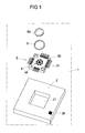
- Fig. 1 shows a schematic exploded view of a lighting module 1, which is used individually or with a plurality of identically or identically constructed lighting modules in a lighting device such as a headlight, a surface light or the like.
- the light module 1 is composed in a basic form of a designed as a printed circuit board module carrier 2 with a module electronics 20 arranged thereon and a light source 3, consisting of a board 30 with a plurality of arranged on the board 30 light emitting diodes (LEDs) 4, also on the board 30 arranged temperature sensor 34 and arranged on the edge of the board 30, as formed Lötfahen contacts 31 which are connected to the LEDs 4 and the module electronics 20.
- LEDs light emitting diodes
- the LEDs 4 are composed of several LEDs that emit light of different wavelengths, ie different color, whereby several LEDs can also emit the same wavelength, ie light of the same color.
- By closely arranging the LEDs 4 on the board 30 is already an adjustable by the selection of the LEDs Light mixture generated from the different colors, which can be optimized by additional measures such as optical light bundling and light mixing and kept constant by other control and regulatory measures regardless of, for example, the temperature in order to set a desired color temperature, brightness and the like.
- the light source 3 is used for space-saving arrangement and extension of the modularity of the light module 1 in a recess 21 of the module carrier 2, so that the configuration of the light source 3 can be independent of the configuration of the module carrier 2 and the module electronics 20, if it is ensured that the interfaces between the light source 3 and the module electronics 20 are designed accordingly.
- the light source 3 and the board 30 according to the in the Fig. 10 to 13 illustrated embodiment, arranged on the base of a heat sink and this are inserted through the recess 21 of the module carrier 2.
- a ring 5 can be connected to the circuit board 30 of the light source 3, which comprises the LEDs 4 and optionally with a preferably optically active, that of the LEDs 4 discharged light rays collecting potting compound 6 is filled.
- the potting compound 6 can cover the LEDs 4 of the light source 3 in a bell-shaped or cylindrical manner, without the LEDs 4 being enclosed by the ring 5.
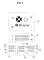
- Fig. 2 shows a schematic representation of a plurality of lighting modules 1.1, 1.2 to 1.N with a coupled to the light modules 1.1, 1.2 to 1.N primary optics 7.1, 7.2 to 7.N and all primary optics 7.1, 7.2 to 7.N associated secondary optics 8 at a Tertiäroptik 9 can be coupled.
- the primary optics 7 essentially serves for bundling the light emitted by the light source 3 of the light module 1 by means of a light bundling device 71 and / or for uniform brightness distribution of the light emitted by the LEDs 4 of the light source 3 by means of a light mixing device 72 and / or color mixing of the light of different wavelength and thus different color emitting LEDs 4 of the light source 3 by means of a color mixing device 73, wherein at least parts of Primary optics 7 made of polymethylmethacrylate (PMMA) or polycarbonate (PC) exist.
- PMMA polymethylmethacrylate
- PC polycarbonate
- the secondary optics 8 and the tertiary optics 9 form an optional and / or movable part, which can be adapted to specific requirements that an extended light module of modular lighting device are provided.
- the secondary optics 8 is used in particular for beam shaping, but is also used for supplementary light and / or color mixing. It consists in a particular embodiment of a zoom optics, the two mutually in the emission direction of the light module 1 motor, pneumatically or hydraulically adjustable microlens plates 81, 82 for focusing, i. for expanding or combining the light beams emitted by the LEDs 4.
- a headlamp which in operation corresponds largely to a conventional studio or film headlamp and which has a dynamically variable halfway angle of e.g. about 20 ° - 60 °.
- the secondary optics 8 can also consist of a condenser lens, in particular of a honeycomb condenser.
- the light module 1 is according to the Fig. 1 and 2 in its basic form from the module carrier 2 with module electronics arranged thereon and the light source 3 arranged on the circuit board 30, and results in a compact, universally usable, microprocessor-controlled lighting device with LEDs or LEDs 4, which has a very good color reproduction and a large adjustable color space.
- the optionally arranged as an extension of the light module 1 to the LEDs 4 of the light source 3, preferably cylindrical or oval ring 5 is connected for example by means of an adhesive connection with the LEDs 4 receiving board 30, preferably consists of plastic and is on the LEDs 4 facing inside white or mirrored to optimally reflect the light rays, and has a defined distance to the outer LEDs 4 and a predetermined height.
- the transparent potting compound 6 serves as protection both for the LEDs 4 mounted on the board 30 and for the LEDs 4 with the grid-shaped contacts 31 formed as soldering lugs Fig. 6 connecting tracks 35 and can about it also serve as an optically functional element for the light mixture, light bundling, light scattering or the like of the light emitted by the LEDs 4 light.
- the potting compound 6 fills the space formed by the cylindrical ring 5 by the potting compound 6 is introduced after the connection of the ring 5 with the board 30 of the light source 3 in the space formed within the ring 5.
- the potting compound 6 can be flush with the upper edge of the ring 5, or designed to perform optical functions convex or concave.
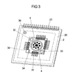
- the inserted into the recess 21 of the module carrier 2 board 30 of the light source 3 is according to Fig. 3 with connecting screws, which are inserted through holes 32, 33 in the corner regions of the board 30, connected to a heat sink that uses 4 different cooling techniques depending on the respective intended or required power of the LEDs 4 and for example as a ventilated heat sink with cooling fins or the like, is designed as a heat pipe or as a liquid-cooled heat sink.
- the connection of the light source 3 with the in Fig. 3 schematically as a dashed frame around the recess 21 shown module electronics 20 via the formed as Lötfahen contacts 31 at the edge of the board 30, which are soldered to the conductor tracks of the module carrier 2.
- the module carrier 2 can also be designed as a ventilated heat sink with cooling fins, as a heat pipe or as a liquid-cooled heat sink.
- the light source 3 or the board 30 can be arranged on the base of a heat sink and this can be inserted through the recess 21 of the module carrier 2, as described below with reference to FIG Fig. 10 to 13 illustrated embodiment is explained.
- a temperature sensor 34 is arranged on the circuit board 30, which detects the board temperature of the board 30 and thus preferably the LEDs 4 bonded to the board 30 and outputs a temperature signal to the module electronics 2.
- the LEDs 401-442 originate from a brightness group, which consists of the uppermost third of all available brightness groups, and are tightly grouped together on the carrier plate 30 for optimal light mixing.
- the LEDs 401-442 of the light source 3 are arranged and selected with respect to their emitted light of different wavelengths so that a variable light mixture is achieved by a separate control of the five and optionally six color groups.
- the in Fig. 5 illustrated circuit diagram of the light source 3 illustrates the serial interconnection of the white light emitting LEDs 401-404 and offset by 180 ° to each other in a rotationally symmetrical arrangement around the white light emitting LEDs 401-404 arranged color LEDs 411-442 and designed as NTC resistor Temperature sensor 34 which is connected to the electrical contacts 34.1 and 34.2 of the grid-shaped arrangement of the contacts formed as Lötfahen 31 of the light source 3.
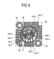
- Fig. 6 shows that to the representations according to the FIGS. 4 and 5 Belonging layout of the connections of the LEDs 401-442 of the light source 3 with the raster-shaped on the edge of the board 30 arranged contacts 31 via tracks 35 and the temperature sensor 34 and illustrates the even with crowded structure of the LEDs 401-442 to achieve an optimal light mixture easily to be laid electrical conductor tracks 35 and the contours of the cylindrical ring 5 of the light source 3 and the diametrically opposed holes 32, 33 for connecting the circuit board 30 of the light source 3 with the module carrier 2 or a heat sink.
- two white light emitting LEDs 401 and 402 or 403 and 404 are connected in series to the contact surfaces 401.1 and 402.2 or 403.1 and 404.2, which are connected to the corresponding contacts 31 on the edge of the board 30 of the light source 3.
- module carrier schematically drawn module electronics 20 has arranged on the double-sided, designed as a printed circuit board module carrier 2 arranged microprocessor circuit which is arranged for example around the light source 3 and the base 161 of the module heat sink 16 receiving recess 21 around and processes the commands received on its serial interface and generates control signals for driving the LEDs 401-442 via the grid-shaped contacts 31, which are connected via the tracks 401.1-442.2 to the individual serially connected LEDs 401-442.
- the actuation of the LEDs 401-442 preferably takes place via precise pulse-width-modulated control signals whose pulse width can be set from 0% to 100% for continuous dimming of the LEDs.
- the double-sided copper-clad double-sided in SMD (Service Mounted Devices) - equipped technology module carrier 2 for example, the outer dimensions 36 x 36 mm with a recess of 14 x 14 mm for receiving the light source 3 and contains at least one contact strip 23 as the outer terminal and the inner terminals formed as soldering surfaces to the contacts 31 of the light source 3.
- the individual, the module electronics 20 containing lighting modules 1 work as bus slaves and start no spontaneous communication.
- an external controller connected to the module electronics 20 of the individual lighting modules 1 via serial interfaces carries out a periodic inquiry of all board temperatures of the lighting modules 1 in the overall system and then sends the highest determined temperature the individual module electronics 20 of the lighting modules 1 of the entire system back.
- all lighting modules 1 perform a brightness adjustment on the basis of this temperature value sent back to the lighting modules 1 in order to compensate for brightness differences between the individual lighting modules 1 that are caused by convection.
- the color signals delivered to the LEDs 4 of the individual lighting modules 1 in one embodiment have a maximum voltage of 9 V at a maximum current of 350 mA.
- the pulse width modulation is performed with a frequency f ⁇ 25 kHz at a 12-bit resolution.
- the effective current regulation takes place with a tolerance of ⁇ I EFF ⁇ + 1% by controlling the maximum current value I MAX to ⁇ 10% and / or balancing the pulse width of the pulse width modulation.
- Fig. 7 shows a functional diagram of the module electronics 20 for driving six LED groups, each with two series-connected, light of the same wavelength emitting LEDs 401, 402; 403, 404; 411, 412; 421, 422; 431, 432; 441, 442 and for controlling the light mixture emitted by the LEDs by a brightness control of the individual LED groups by means of a pulse width modulated control voltage and control of a temperature-stabilized current source for powering the LED groups.
- the module electronics 20 includes a microcontroller 60 which outputs six pulse width modulated control voltages PWM1 to PWM6 to six identically constructed constant current sources 61 to 66.
- the microcontroller 60 is connected via a serial interface SER A and SER B with an external controller and has inputs AIN1 and AIN2, which are connected via amplifiers 37, 38 to a temperature sensor 34 and a brightness or color sensor 36 of the light module.
- the identically structured current sources 61 to 66 are very well temperature-stabilized and contain a temperature-stabilized constant current source 67 which is connected to outputs PWM1 to PWM6 of the pulse width modulated control voltages emitting outputs PWM1 to PWM6 of the microcontroller 60 and via a resistor 69 to a supply voltage U LED1 to U LED6 are connected.
- the temperature-stabilized constant current source 67 has its output connected to the anode of the series-connected LEDs of an LED group, each of which emits light of the same wavelength, and to the control terminal of an electronic switch 68, connected on the one hand to the cathode of the series-connected LEDs and on the other hand to ground potential GND is connected.
- the temperature-stabilized constant current source 67 is characterized by a fast and clean switching with a switching frequency of 20 to 40 kHz. In order to keep the power loss of the light module as low as possible, the different in the manufacturing technology LED chips with up to six different supply voltages U LED1 to LED6 are fed.
- the arrangement of the temperature-stabilized current sources 61-66 on the module carrier of the lighting module improves the modularity of the system and simplifies the power supply.
- the light module only needs five interfaces, ie a connection of the light module via five lines, namely two supply voltages V LED1 and V LED2 , ground potential GND and the serial interfaces SER A and SER B with an external controller 10 ( FIG . Fig. 15 ) for higher-level control and regulation of a plurality of similarly constructed lighting modules.
- Fig. 8 is a plan view of a light source 3 'with an alternative arrangement of eleven LEDs 405 to 443 shown on a board 30 that emit light of different colors.
- the LEDs 405 to 443 are arranged in the center and on two concentric circles around the center and on the two concentric circles at equal angular intervals, so that on the one hand ensures that the LEDs 405 to 443 closely to each other on the board 30 and on the other hand outer circular boundary result, which is optimally suitable for flanging an optic to the light source 3 '.
- white, especially warm white light emitting LED chips 406 to 410 are arranged, while on the inside of the two concentric circles a first, blue light emitting LED chip 433, a yellow or amber light emitting LED Chip 443, a second blue emitting LED chip 434, a red light emitting LED chip 413 and a green light emitting LED chip 423 are arranged.
- Both the LED chips 405 to 443 arranged on the inner circle and on the outer circle of the two concentric circles are arranged at equal angular intervals of 72 ° and the LED chips 413, 423, 433 arranged on the inner of the two concentric circles , 443 and 434 offset by an angle of 36 ° with respect to the arranged on the outer of the two concentric circles LED chips 406-410.
- Fig. 9 shows an exemplary embodiment of a perspective view of a suitable for a juxtaposition of similar lighting modules lighting module 1, which consists of a square, designed as a printed circuit board module carrier 2, a light source 3 or 3 'with a plurality of, in this embodiment, twelve LEDs 4, the pair of light of different wavelengths and thus give off color, a ring 5 and a contact strip 23 is composed.
- lighting devices can also be formed of lighting modules with triangular module carrier 2, which analogous to the above with reference to the Fig. 9 described light module semicircular fastening receptacles which are closed at a juxtaposition of further, similarly trained triangular support plates to a circular shape for receiving fasteners.
- any geometric shapes for a lighting device such as a headlight, light panels, ring lights for camera lenses, light chains, LED Snakes or LED chains with zigzag strung together panels and the like can be generated.
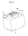
- a light module 1 shown in its individual parts and in the assembled state, which is characterized in addition to optimal heat dissipation by a safe and simple mechanical connection between the light module 1 and a headlight housing or a cooling device, the module support 2 is not mechanically stressed and the light source 3 is arranged so that the beam path of the LEDs 4 of the light source 3 is not disturbed by fasteners on the module carrier 2 or by electronic components of the module electronics 20, which are arranged on the designed as a cuboid metal core board 300 module carrier 2, so that the in the direction of radiation
- the light source 3 downstream optics can capture the emitted light from the LEDs 4 and can make very effective.
- Light source 3 of this light module shown schematically in perspective is composed of twelve LEDs 401-403, 411, 412, 421, 422, 431, 432 and 441, 442 and a temperature sensor 34 which are arranged on the metal core board 300 together with conductor tracks 35. Led from the LEDs 401-403, 411, 412, 421, 422, 431, 432 and 441, 442 and the temperature sensor 34 to the edges of the cuboid metal core board 300, where they are connected via a direct wire or bond connection with the Module electronics are connected. This structure allows the construction of a very small and thus cost-effective light source with high luminance.
- the metal core board 300 is according to Fig. 11 connected to the surface of a base 161 of a module heat sink 16, which has a cuboid or cube shape, consists of a very good heat conducting material such as copper or aluminum and according to Fig. 13 on its underside has a threaded hole 162 through which a safe and simple mechanical connection of the entire lighting module with a headlight housing or a cooling device on standard fasteners, such as screws, pins and the like can be made.
- the module heat sink 16 can be connected via coolant lines to a heat exchanger.
- a liquid cooling of the module heat sink 16 and thus the light module is useful, for example, in the arrangement of a lighting device to a telescope below a studio ceiling and allows for effective cooling, since only the parts are generated which generate heat.
- Another possibility is to connect the module heatsink 16 or the lighting device via coolant lines with an external control and cooling device or to use a trained as a single spot camera light or small array with a heat pipe (heat pipe) and a fan heatsink.
- the over the surface of the module heat sink 16 protruding base 161 has a surface which corresponds approximately to the surface of the metal core board 300. Holes for receiving fastening elements, such as screws 171 or notched nails 172, are embedded in the surface of the module heat sink 16 on the side of the base 161, which allow a secure connection to the module carrier 2 in the form of a printed circuit board Fig.
- the module carrier 2 By the connection of the module carrier 2 with the module heat sink 16 via the fastening elements 171 and 172 it is ensured that the module carrier 2 is not mechanically loaded and that by plugging the module carrier 2 on the base 161 of the module heat sink 16, a flat, space-saving construction is achieved.
- the entire light-emitting module can thus be attached via the arranged at the bottom of the module heat sink 16 threaded bore 162 and a screwed with the threaded hole 162 fastener to a larger heat sink or a spotlight housing, where it is thermally advantageous if the light source 3 directly on the module Heat sink 16 is coupled.
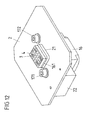
- connection of the module electronics with a in Fig. 15 shown external controller 10 is carried out according to Fig. 12 via a contact plug 22 which is arranged on the underside of the module carrier 2 and according to Fig. 13 has five contacts at a voltage supply of the module electronics with two different supply voltages.
- a connectable to the contact plug 220 contact socket accordingly has five sockets, which are connected to two voltage sources, a ground potential and two contacts of a serial interface to the external controller.
- Fig. 10 to 13 shown light module allows a very simple and space-saving, flat arrangement of several similar lighting modules on the board of an LED panel (motherboard or backplane), which is connected, for example, with a lighting device, such as a headlight.
- a lighting device such as a headlight.
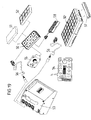
- FIG. 14 to 16 An exemplary embodiment of such a board 18 designed as a motherboard, which accommodates, inter alia, the external controller 10 and further storage, control and interface elements of an LED panel for an LED lighting system is in the Fig. 14 to 16 shown.
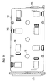
- Fig. 14 shows a plan view of the board 18 of an LED panel, which has, inter alia, an external controller and other storage, control and interface elements.
- the rectangular board 18 eight openings 181 for inserting the module heatsink 25 of the light module 2 and eight sockets 182 for receiving the contact plug 23 of the individual lighting modules 2, each with a different orientation of the openings 181 and sockets 182 for the module heatsink 25 and Contact plug 23 is provided.
- the plan view Fig. 14 omitted on the board 18 on both sides arranged electronic components of the storage and control elements.
- the rectangular board On its narrow sides, the rectangular board has 18 input and output connectors 115, 116, which are aligned perpendicular to the plane of the board 18 and inputs and outputs for a in Fig. 18 form the illustrated LED panel. Centered on the board 18 are arranged spaced from each other fastening magnets 19 for fixing an optical device (primary and secondary optics).
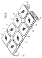
- Fig. 15 and 16 is in an isometric view of the top and bottom of the board 18, the arrangement of the light modules 1 with the module carrier 2, the light source 3 and the LEDs 4, inserted into the openings 181 of the board 18 module heat sink 25 and in the sockets 182 used contact plug 23, and the arrangement of the mounting magnets 19, the unspecified electronic components of the memory and controls of the LED panel and a plurality of input and output connectors 115, 116, 117 shown.
- Fig. 1 to 13 described light module the benefits of an adjustable, precise light source with multiple LEDs and integrated microprocessor circuit, a very large color space and color temperature range of, for example, 2,000 ° K to 25,000 ° K and a very good color reproduction with a color rendering index CRI> 90 between 2200 ° K and 12,000 ° K and a color rendering index CRI> 95 between 3,200 ° K and 6,500 ° K with an LED power of up to 12 W allows.
- a luminous flux up to 300 Im in the setting "white" at 100 ° C junction temperature can be achieved.
- the light module allows up to six independent color channels with a standard configuration in the colors red, green, blue, white and amber and a very high luminance through the circular arrangement of, for example, twelve LED chips with a diameter of 5.6 mm.
- the field of application of the light module can be extended by the coupling of optics, even with a narrow scattering angle, without color divergences occurring.
- the modular design of the lighting unit allows a stringing together of a variety of equally behaving lighting modules and a summary of the control on an external controller with download function for the operating program and the parameters and a data exchange via a serial interface.
- the light mixture emitted by the light source 3 is treated further individually for each lighting module 1 or in a total of a plurality of lighting modules 1 combined to form a lighting device.
- a total system for a lighting device designed as an LED panel, headlight, light chain or the like can be formed from a number of N light modules 1, wherein one of the light modules 1 is designed as a master module and contains the identification and calibration data of the lighting device, while the other lighting modules 1 are designed as slave modules. All lighting modules 1 of the overall system communicate in such an arrangement with an external controller or controller.
- N lighting modules 1 to an overall system will be described below with reference to the in the Fig. 17 and 18 illustrated LED lighting device explained.
- Fig. 17 shows a schematic representation of the circuit structure of an interconnection of N lighting modules 1.1 to 1.N to a lighting device, which is controlled by an external controller 10.
- the lighting modules 1.1 to 1.N each contain a light source 3.1 to 3.N, a module electronics 20.1 to 20.N and an optic, in the exemplary embodiment illustrated here a primary optics 7.1 to 7.N.
- the module electronics 20.1 to 20.N of the individual lighting modules 1.1 to 1.N are connected via a serial interface 14 to the external controller 10 for driving and automatic control of the N lighting modules 1.1 to 1.N, the multiple analog and digital inputs and outputs and a Microprocessor 11 has its own, non-volatile memory 12.
- the external controller 10 receives data and control commands via a control line 15 and outputs corresponding color control signals to the lighting modules 1.1 to 1.N.
- an automatic temperature compensation by means of stored in the non-volatile memory 12 characteristics is performed so that the color and brightness of the lighting modules 1.1 to 1.N remains constant.
- the temperature values emitted by the temperature sensors arranged on the light sources 3.1 to 3.N are also read in and processed by the external controller 10.
- an additional photosensor 13 can be integrated into the external controller 10 for monitoring and, if appropriate, compensation for long-term effects.
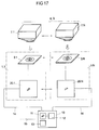
- Fig. 18 shows an isometric view of an LED panel having a rectangular housing frame 11 with closed, designed as a heat sink surface 110 with cooling fins 113 bottom, in which the light modules 1 receiving board 18 according to the Fig. 14 to 16 is used.
- the LED panel has at its narrow sides input connector 115 and output connector 116 for connection to a power supply and control device with an external controller or for connection to the respective LED panel associated with decentralized control element and / or an accumulator for autonomous Power supply of the LED panel.
- the board 18 eight identically formed lighting modules 1 are used and mechanically and electrically connected to the circuit board 18. Between the arranged in two rows and eight columns lighting modules 1 three mounting magnets 19 are arranged, which serve for fixing an attachable to the housing frame 11 optical device, for example in the form of a soft-optics or spot optics.
- a connecting element can be used and positively connected to the LED panel.
- a connecting element is used in particular a connecting pin connected or connectable to a tripod, a rig or other support member.
- the receptacles 111, 112, 114 are T-shaped in the manner of a slotted box profile with and without additional groove, while the connecting pin has a corresponding counter-profile, by attaching the connecting pin from the side of the housing frame 11 in the receptacles 111, 112, 114 can be used and positively engages in recesses.
- primary optics 7.1 to 7.N associated with the lighting modules 1.1 to 1.N can be connected as moving parts light couplings, which consist of a light guide or a mirror or a prism system for light extraction.
- individual secondary optics assigned to each primary optics 7.1 to 7.N or all primary optics 7.1 to 7.N may together be provided with secondary optics for beamforming, which may or may not be focusable by motor, pneumatically or hydraulically.
- a secondary optics for beam shaping serves to variably widen the light emitted by the primary optics 7.1 to 7.N or the light sources 3.1 to 3.N to larger or smaller half-beam angles, with those of the primary optics 7.1 to 7.N and the light sources 3.1 to 3.N emitted light beams by a corresponding lens arrangement are narrow and arbitrarily wide feasible, so that the focus is individually adjustable.
- secondary optics may be optical accessories in the form of tertiary optics for changing the emission angle, for example by mutually displaceable lens plates, or a diaphragm device in the form of winged gates for the lateral limitation of the light emitted by the illumination device, or in the form of irises, scrims, gobos and connect the like.
- lighting modules Due to the modular construction of the lighting device, various combinations of lighting modules are possible, which are equipped either as basic lighting modules in conjunction with a primary optics, a predetermined number of such basic lighting modules are combined with primary optics to a lighting device, optionally with a light coupling, secondary optics or with optical accessories.
- a predetermined number of such basic lighting modules are combined with primary optics to a lighting device, optionally with a light coupling, secondary optics or with optical accessories.
- several light modules can be combined to headlights or area lights that are mechanically and electrically coupled to each other via quick connections, the light-emitting surface of the headlight or the surface light can be designed arbitrarily, for example, to allow circular, square or elongated radiating surfaces.
- modularly arranged lighting modules have joints at certain points, so that either a compact panel with any geometric shape of the light-emitting surface is formed, which is circular, square, rectangular or designed as a light strip, in which several lighting modules are connected in series in a row.
- Fig. 19 shows an overview diagram of the individual functional elements of a modular lighting system with a single LED panel 50, are arranged in the eight light modules 1 with a composed of light of different wavelengths and color emitting LEDs light source.
- the LED panel 50 forms a luminous body, which in addition can be placed on top of the LED panel 50 soft optics 61 or spot optics 52 for additional light mixing of the light of different wavelength and thus color emitting LEDs and a desired beam shaping is expandable.
- the LED panels 50 have lateral electromechanical connectors, via which a plurality of LED panels 50 can be electrically and mechanically connected to an LED panel row. Via additional cross connectors 57, a plurality of LED panel rows can be combined to form an LED panel group 50 'with a matrix-shaped structure.
- a single control element 55 for decentralized control of the relevant LED panel 50 or an LED panel group 50' attachable and allows individual control or setting of light parameters of the light modules of the respective LED panel 50 or the LED panel group 50 '.
- the control element 55 can be disconnected from the LED panel 50 again after the entry of data or adjustment of the parameters.
- a central power control unit 53, 54 serves to supply power to an LED panel 50 or an LED panel group 50 'as well as to input desired values for activation the lighting modules 1 of the individual LED panels 50 and consists of a power supply and docking station 53 and a controller 54 which can be connected to the power supply and docking station 53 or operated via a radio or line connection separately from the power supply and docking station 53 ,
- the power supply and docking station 53 has a plurality of sockets, which establishes an electrical connection for power supply and control of the LED panel 50 or the LED panel group 50 'via connection cable 56.
Landscapes
- Engineering & Computer Science (AREA)
- Microelectronics & Electronic Packaging (AREA)
- General Engineering & Computer Science (AREA)
- Physics & Mathematics (AREA)
- Optics & Photonics (AREA)
- Non-Portable Lighting Devices Or Systems Thereof (AREA)
- Arrangement Of Elements, Cooling, Sealing, Or The Like Of Lighting Devices (AREA)
- Led Devices (AREA)
- Circuit Arrangement For Electric Light Sources In General (AREA)
Applications Claiming Priority (2)
| Application Number | Priority Date | Filing Date | Title |
|---|---|---|---|
| DE102007044567A DE102007044567A1 (de) | 2007-09-07 | 2007-09-07 | Beleuchtungseinrichtung mit mehreren steuerbaren Leuchtdioden |
| PCT/EP2008/060892 WO2009033922A2 (de) | 2007-09-07 | 2008-08-20 | Beleuchtungseinrichtung mit mehreren steuerbaren leuchtdioden |
Publications (2)
| Publication Number | Publication Date |
|---|---|
| EP2185856A2 EP2185856A2 (de) | 2010-05-19 |
| EP2185856B1 true EP2185856B1 (de) | 2011-10-19 |
Family
ID=40328555
Family Applications (1)
| Application Number | Title | Priority Date | Filing Date |
|---|---|---|---|
| EP08803116A Active EP2185856B1 (de) | 2007-09-07 | 2008-08-20 | Beleuchtungseinrichtung mit mehreren steuerbaren leuchtdioden |
Country Status (6)
Families Citing this family (72)
| Publication number | Priority date | Publication date | Assignee | Title |
|---|---|---|---|---|
| US9185123B2 (en) | 2008-02-12 | 2015-11-10 | Finsphere Corporation | System and method for mobile identity protection for online user authentication |
| US8280348B2 (en) | 2007-03-16 | 2012-10-02 | Finsphere Corporation | System and method for identity protection using mobile device signaling network derived location pattern recognition |
| DE102007044566A1 (de) | 2007-09-07 | 2009-03-12 | Arnold & Richter Cine Technik Gmbh & Co. Betriebs Kg | Beleuchtungssystem |
| USD603350S1 (en) | 2008-04-04 | 2009-11-03 | Arnold & Richter Cine Technik Gmbh & Co. Betriebs Kg | Hand held controller for lighting system |
| USD602877S1 (en) | 2008-10-03 | 2009-10-27 | Arnold & Richter Cine Technik Gmbh & Co. Betriebs Kg | Transceiver for lighting system |
| DE102008059468A1 (de) * | 2008-11-28 | 2010-06-24 | Osram Opto Semiconductors Gmbh | Optoelektronische Lampe |
| DE102009031403A1 (de) * | 2009-07-01 | 2011-01-05 | Osram Gesellschaft mit beschränkter Haftung | Leuchtelement, Leuchte und Verfahren zum Betrieb des Leuchtelements |
| DE202009011500U1 (de) | 2009-08-20 | 2010-12-30 | Arnold & Richter Cine Technik Gmbh & Co. Betriebs Kg | Optisches System für eine LED-Leuchte |
| JP2011066133A (ja) * | 2009-09-16 | 2011-03-31 | Koito Mfg Co Ltd | 発光モジュール及び車輌用灯具 |
| US8757838B2 (en) | 2010-01-22 | 2014-06-24 | Koninklijke Philips N.V. | Lighting device comprising a plurality of light emitting tiles |
| DE102010014613A1 (de) * | 2010-04-09 | 2011-10-13 | Ledon Oled Lighting Gmbh & Co.Kg | Flächige Leuchtkörper, Anordnung von flächigen Leuchtkörpern und Verfahren zum Herstellen flächiger Leuchtkörper |
| DE102010014972A1 (de) * | 2010-04-14 | 2011-10-20 | GRAH Automotive d.o.o. | Leuchte mit konstantstrombetriebenen LED-Leuchtmitteln |
| ITVR20100089A1 (it) * | 2010-04-29 | 2011-10-30 | Lubtech S R L | Corpo illuminante a led |
| MX342297B (es) * | 2010-05-04 | 2016-09-23 | Xicato Inc | Conexion electrica flexible de un dispositivo de iluminacion basado en led a un accesorio de luz. |
| DE102010023342A1 (de) | 2010-06-10 | 2011-12-15 | Osram Opto Semiconductors Gmbh | Leuchtdiodenanordnung und Leuchtmittel insbesondere mit solch einer Leuchtdiodenanordnung |
| US9147222B2 (en) | 2010-06-23 | 2015-09-29 | Digimarc Corporation | Detecting encoded signals under adverse lighting conditions using adaptive signal detection |
| EP2405716B1 (de) * | 2010-07-09 | 2017-04-19 | odelo GmbH | Leuchtmittel und Verfahren zu dessen Stromversorgung |
| DE102010044987A1 (de) * | 2010-09-10 | 2012-03-15 | Osram Opto Semiconductors Gmbh | Optoelektronisches Halbleiterbauelement und Verfahren zu dessen Herstellung |
| DE112011103437A5 (de) * | 2010-10-12 | 2013-08-08 | Tridonic Gmbh & Co. Kg | Betriebsgerät zur Ausgabe von Temperatur-Information |
| US10630820B2 (en) | 2011-03-11 | 2020-04-21 | Ilumi Solutions, Inc. | Wireless communication methods |
| US10321541B2 (en) * | 2011-03-11 | 2019-06-11 | Ilumi Solutions, Inc. | LED lighting device |
| DE202011100791U1 (de) * | 2011-05-17 | 2012-08-24 | Christian Braun | Leuchte mit farblich variablem Licht |
| GB201108802D0 (en) * | 2011-05-25 | 2011-07-06 | Benmore Ventures Ltd | Modular lighting systems |
| DE102011111970A1 (de) | 2011-08-31 | 2013-02-28 | Abb Ag | LED-Modul-System mit einem LED-Modul |
| CN103635740B (zh) * | 2011-09-27 | 2016-10-12 | 东芝照明技术株式会社 | 灯装置及照明装置 |
| WO2013060351A1 (de) | 2011-10-24 | 2013-05-02 | Osram Ag | Beleuchtungseinrichtung mit einer optischen anordnung zur farbmischung von lichtquellen |
| US9293447B2 (en) * | 2012-01-19 | 2016-03-22 | Epistar Corporation | LED thermal protection structures |
| CN104365178B (zh) * | 2012-01-20 | 2018-01-12 | 奥斯兰姆施尔凡尼亚公司 | 照明系统 |
| US8888320B2 (en) * | 2012-01-27 | 2014-11-18 | Hubbell Incorporated | Prismatic LED module for luminaire |
| US9192008B2 (en) * | 2012-03-26 | 2015-11-17 | B/E Aerospace, Inc. | Reduced-size modular LED washlight component |
| DE202012003936U1 (de) * | 2012-04-18 | 2013-07-22 | Oase Gmbh | Lichtsystem |
| DE102012013963A1 (de) * | 2012-07-13 | 2014-01-16 | Ambright GmbH | Sensorleuchte |
| CN202931629U (zh) * | 2012-11-09 | 2013-05-08 | 禾财记兴业有限公司 | 具调光功能的led发光模块 |
| DE102012222959B4 (de) * | 2012-12-12 | 2015-04-02 | Semikron Elektronik Gmbh & Co. Kg | Leistungsbauelementeinrichtung |
| US9153171B2 (en) | 2012-12-17 | 2015-10-06 | LuxVue Technology Corporation | Smart pixel lighting and display microcontroller |
| CN104125671A (zh) * | 2013-04-24 | 2014-10-29 | 鸿富锦精密工业(武汉)有限公司 | 照明装置 |
| CH707975A1 (de) | 2013-04-30 | 2014-10-31 | Regent Beleuchtungskörper Ag | Leuchte mit optoelektronischer Einheit. |
| ES2473165B1 (es) * | 2013-10-14 | 2015-06-02 | C. M. Salvi S.L. | "sistema de control de una pluralidad de luminarias de tipo led y luminaria correspondiente" |
| DE202013010390U1 (de) | 2013-11-20 | 2014-01-23 | Berling Living Lights Gmbh | Halbleiterlichtquelle |
| JP5608827B1 (ja) * | 2014-01-27 | 2014-10-15 | ターンオン有限会社 | 多色ペンライト |
| US10194503B2 (en) | 2014-04-02 | 2019-01-29 | Abl Ip Holding Llc | Composite light source systems and methods |
| DE202014102430U1 (de) * | 2014-05-23 | 2015-05-27 | Bernd Mitecki | Leuchtvorrichtung umfassend mindestens eine Halbleiterlichtquelle und Fassadenleuchtvorrichtung mit mindestens eine Halbleiterlichtquelle |
| EP3298323B1 (en) * | 2015-05-19 | 2019-10-02 | Signify Holding B.V. | Lighting device comprising a split lighting engine |
| US10448537B2 (en) * | 2015-06-11 | 2019-10-15 | Toray Industries, Inc. | Power supply device, photochemical reaction device and method in which same is used, and lactam production method |
| KR101608418B1 (ko) | 2015-06-17 | 2016-04-11 | 레이져라이팅(주) | 기능 확장식 엘이디 조명용 제어 기판 및 제어 기판 조립체 |
| DE102015212177A1 (de) * | 2015-06-30 | 2017-01-05 | Osram Gmbh | Schaltungsträger für eine elektronische Schaltung und Verfahren zum Herstellen eines derartigen Schaltungsträgers |
| DE102015212169A1 (de) * | 2015-06-30 | 2017-01-05 | Osram Gmbh | Schaltungsträger für eine elektronische Schaltung und Verfahren zum Herstellen eines derartigen Schaltungsträgers |
| US10339796B2 (en) | 2015-07-07 | 2019-07-02 | Ilumi Sulutions, Inc. | Wireless control device and methods thereof |
| WO2017007926A1 (en) | 2015-07-07 | 2017-01-12 | Ilumi Solutions, Inc. | Wireless communication methods |
| WO2017114428A1 (zh) * | 2015-12-29 | 2017-07-06 | 欧普照明股份有限公司 | 光源模组和照明装置 |
| US20170211790A1 (en) * | 2016-01-25 | 2017-07-27 | Ming-Hui Lin | Light-emitting module and lighting device including the same |
| EP3426976B1 (en) | 2016-03-11 | 2021-02-24 | TE Connectivity Nederland B.V. | Socket assembly, light emitter module, and lighting system |
| DE102016206275B4 (de) * | 2016-04-14 | 2023-07-20 | Volkswagen Aktiengesellschaft | Verfahren zum Betreiben wenigstens einer Beleuchtungsvorrichtung eines stillstehenden Kraftfahrzeugs |
| EP3244125A1 (fr) * | 2016-05-13 | 2017-11-15 | Stephane Bochenek | Dispositif d'éclairage formé à partir d'éléments lumineux et rampe d'éclairage formée par une pluralité de tels dispositifs d'éclairage |
| WO2017200761A1 (en) * | 2016-05-20 | 2017-11-23 | JST Performance, LLC | Method and apparatus for a signal indicator light |
| DE102016221772A1 (de) * | 2016-11-07 | 2018-05-09 | Bayerische Motoren Werke Aktiengesellschaft | Beleuchtungsvorrichtung und Beleuchtungssystem für ein Kraftfahrzeug sowie Verfahren zum Betreiben eines Beleuchtungssystems für ein Kraftfahrzeug |
| DE102016221771A1 (de) | 2016-11-07 | 2018-05-09 | Bayerische Motoren Werke Aktiengesellschaft | Beleuchtungsvorrichtung und Beleuchtungssystem für ein Kraftfahrzeug sowie Verfahren zum Betreiben eines Beleuchtungssystems für ein Kraftfahrzeug |
| KR102618389B1 (ko) * | 2017-11-30 | 2023-12-27 | 엘지디스플레이 주식회사 | 전계 발광 표시장치와 그 구동 방법 |
| JP6469904B1 (ja) * | 2018-01-24 | 2019-02-13 | 村上 治 | Led輝度調節色温度調節を遠隔制御する電気回路及びその制御方法 |
| JP7031547B2 (ja) * | 2018-09-27 | 2022-03-08 | 豊田合成株式会社 | 発光装置 |
| DE102019102124A1 (de) * | 2019-01-29 | 2020-07-30 | Bayerische Motoren Werke Aktiengesellschaft | Beleuchtungsvorrichtung für ein Kraftfahrzeug |
| US11339947B2 (en) * | 2019-03-21 | 2022-05-24 | Panor Corp. | Systems and methods for LED lens heating |
| WO2020247864A1 (en) * | 2019-06-05 | 2020-12-10 | FOHSE Inc. | Led luminaire thermal management system |
| US11716815B2 (en) | 2020-01-24 | 2023-08-01 | Osram Gmbh | LED chip insert, lighting device, lighting module, and method of manufacturing the lighting device |
| JP2023528260A (ja) | 2020-05-18 | 2023-07-04 | ルミレッズ リミテッド ライアビリティ カンパニー | カバーの特徴に基づくエミッタのための駆動電流の適合 |
| DE202020002858U1 (de) | 2020-07-03 | 2020-10-04 | Denis Bronsert | Anordnung zur Ansteuerung von LED's |
| RU2739704C1 (ru) * | 2020-09-29 | 2020-12-28 | Дмитрий Николаевич Карпенко | Устройство и система модульного равномерного освещения |
| FR3116589B1 (fr) * | 2020-11-23 | 2025-08-15 | Airstar Sas | Dispositif d'éclairage |
| US11737181B2 (en) * | 2020-12-23 | 2023-08-22 | Hyundai Mobis Co., Ltd. | Apparatus for controlling lamp and method thereof |
| US11672067B2 (en) * | 2021-01-29 | 2023-06-06 | Snap-On Incorporated | Circuit board with sensor controlled lights and end-to-end connection |
| TWM618996U (zh) * | 2021-06-02 | 2021-11-01 | 品威電子國際股份有限公司 | 發光燈箱 |
| EP4527286A1 (en) | 2023-09-21 | 2025-03-26 | OculoWise | Light source, system of light sources, and device for retinal diagnostic and/or therapy |
Family Cites Families (41)
| Publication number | Priority date | Publication date | Assignee | Title |
|---|---|---|---|---|
| USD264460S (en) | 1979-04-09 | 1982-05-18 | Telefonaktiebolaget L M Ericsson | Protector terminal box |
| USD297527S (en) | 1986-05-29 | 1988-09-06 | Rally Manufacturing, Inc. | Lighted automobile ceiling console containing digital clock, compass and thermometer |
| DE8713155U1 (de) | 1987-09-30 | 1987-12-10 | La Télémécanique Electrique, Nanterre, Hauts-de-Seine | Schalt- und/oder Signalisiergerät |
| USD356567S (en) | 1993-07-22 | 1995-03-21 | Magnadyne Corporation | Input selector switch |
| USD368429S (en) | 1993-08-09 | 1996-04-02 | Serco Mold, Inc. | Electronic equipment container |
| US7014336B1 (en) * | 1999-11-18 | 2006-03-21 | Color Kinetics Incorporated | Systems and methods for generating and modulating illumination conditions |
| TW408497B (en) | 1997-11-25 | 2000-10-11 | Matsushita Electric Works Ltd | LED illuminating apparatus |
| AU140191S (en) | 1999-02-08 | 2000-03-28 | Nokia Mobile Phones Ltd | A battery |
| USD506065S1 (en) | 2000-12-25 | 2005-06-14 | Nintendo Co., Ltd. | Rechargeable battery storage case |
| EP1393599B1 (en) * | 2001-05-30 | 2010-05-05 | Philips Solid-State Lighting Solutions, Inc. | Methods and apparatus for controlling devices in a networked lighting system |
| FR2830314B1 (fr) * | 2001-10-03 | 2004-04-16 | Chanel | Dispositif d'eclairage a illumination variable, notamment pour maquillage ou photographie |
| USD477286S1 (en) | 2002-02-12 | 2003-07-15 | Leviton Manufacturing Co., Inc. | Dual rotary dimmer and fan speed control |
| USD489337S1 (en) | 2002-04-17 | 2004-05-04 | Black & Decker Inc. | Home automation module |
| US6998594B2 (en) * | 2002-06-25 | 2006-02-14 | Koninklijke Philips Electronics N.V. | Method for maintaining light characteristics from a multi-chip LED package |
| JP2004071271A (ja) * | 2002-08-05 | 2004-03-04 | Shigemasa Kitajima | 面発光ユニット |
| US7274302B2 (en) | 2003-05-12 | 2007-09-25 | Usa Signal Technology, Llc | Light emitting diode traffic control device |
| DE20309033U1 (de) * | 2003-06-11 | 2003-12-04 | Dr. Adrian Mahlkow Out E.V. | Modul für variable, langzeitstabile Licht- und Farbwiedergabe |
| JP5017824B2 (ja) | 2004-09-15 | 2012-09-05 | トヨタ自動車株式会社 | 密閉型電池及び組電池 |
| USD516503S1 (en) | 2004-10-20 | 2006-03-07 | Sony Corporation | Battery |
| DE202004016637U1 (de) | 2004-10-27 | 2005-01-05 | Osram Opto Semiconductors Gmbh | Beleuchtungseinrichtung |
| DE102004062990A1 (de) | 2004-12-22 | 2006-07-06 | Patent-Treuhand-Gesellschaft für elektrische Glühlampen mbH | Beleuchtungseinrichtung mit mindestens einer Leuchtdiode und Fahrzeugscheinwerfer |
| US7712948B2 (en) | 2005-02-02 | 2010-05-11 | Koninklijke Philips Electronics N.V. | Light-source module and holder therefor |
| USD548684S1 (en) | 2005-03-18 | 2007-08-14 | Toyota Jidosha Kabushiki Kaisha | Storage battery |
| US7893631B2 (en) | 2005-04-06 | 2011-02-22 | Koninklijke Philips Electronics N.V. | White light luminaire with adjustable correlated colour temperature |
| DE102005022832A1 (de) | 2005-05-11 | 2006-11-16 | Arnold & Richter Cine Technik Gmbh & Co. Betriebs Kg | Scheinwerfer für Film- und Videoaufnahmen |
| USD533846S1 (en) | 2005-05-16 | 2006-12-19 | Microgistix, Inc. | Network connection switch |
| KR100645788B1 (ko) * | 2005-08-26 | 2006-11-14 | 주식회사 파이컴 | 백라이트 장치 |
| JP4829577B2 (ja) * | 2005-09-20 | 2011-12-07 | パナソニック電工株式会社 | 発光装置 |
| DE102005058884A1 (de) | 2005-12-09 | 2007-06-14 | Patent-Treuhand-Gesellschaft für elektrische Glühlampen mbH | Leuchtdiodenmodul, Verfahren zur Herstellung eines Leuchtdiodenmoduls und optische Projektionsvorrichtung |
| DE102005061204A1 (de) | 2005-12-21 | 2007-07-05 | Perkinelmer Elcos Gmbh | Beleuchtungsvorrichtung, Beleuchtungssteuergerät und Beleuchtungssystem |
| USD550613S1 (en) | 2006-01-31 | 2007-09-11 | Kyosho Corporation | Rechargeable battery case |
| US20080297068A1 (en) * | 2007-06-01 | 2008-12-04 | Nexxus Lighting, Inc. | Method and System for Lighting Control |
| USD568240S1 (en) | 2007-07-23 | 2008-05-06 | Christian Haydvogel | Battery pack |
| DE102007044566A1 (de) | 2007-09-07 | 2009-03-12 | Arnold & Richter Cine Technik Gmbh & Co. Betriebs Kg | Beleuchtungssystem |
| USD572192S1 (en) | 2007-10-15 | 2008-07-01 | Zhejiang New Mainland Machinery Co., Ltd. | Control panel for generator |
| AU320450S (en) | 2008-02-01 | 2008-07-25 | Matsushita Electric Ind Co Ltd | Battery for portable computer |
| USD603350S1 (en) | 2008-04-04 | 2009-11-03 | Arnold & Richter Cine Technik Gmbh & Co. Betriebs Kg | Hand held controller for lighting system |
| USD602877S1 (en) | 2008-10-03 | 2009-10-27 | Arnold & Richter Cine Technik Gmbh & Co. Betriebs Kg | Transceiver for lighting system |
| US8508116B2 (en) * | 2010-01-27 | 2013-08-13 | Cree, Inc. | Lighting device with multi-chip light emitters, solid state light emitter support members and lighting elements |
| US8773007B2 (en) * | 2010-02-12 | 2014-07-08 | Cree, Inc. | Lighting devices that comprise one or more solid state light emitters |
| US8569974B2 (en) * | 2010-11-01 | 2013-10-29 | Cree, Inc. | Systems and methods for controlling solid state lighting devices and lighting apparatus incorporating such systems and/or methods |
-
2007
- 2007-09-07 DE DE102007044567A patent/DE102007044567A1/de not_active Withdrawn
-
2008
- 2008-08-20 EP EP08803116A patent/EP2185856B1/de active Active
- 2008-08-20 JP JP2010523469A patent/JP5307817B2/ja active Active
- 2008-08-20 AT AT08803116T patent/ATE529689T1/de active
- 2008-08-20 WO PCT/EP2008/060892 patent/WO2009033922A2/de active Application Filing
- 2008-08-20 US US12/676,879 patent/US8299716B2/en active Active
Also Published As
| Publication number | Publication date |
|---|---|
| WO2009033922A3 (de) | 2009-07-02 |
| JP5307817B2 (ja) | 2013-10-02 |
| US8299716B2 (en) | 2012-10-30 |
| US20100219758A1 (en) | 2010-09-02 |
| DE102007044567A1 (de) | 2009-03-12 |
| JP2010538432A (ja) | 2010-12-09 |
| EP2185856A2 (de) | 2010-05-19 |
| WO2009033922A2 (de) | 2009-03-19 |
| ATE529689T1 (de) | 2011-11-15 |
Similar Documents
| Publication | Publication Date | Title |
|---|---|---|
| EP2185856B1 (de) | Beleuchtungseinrichtung mit mehreren steuerbaren leuchtdioden | |
| EP2198197B1 (de) | Beleuchtungssystem | |
| EP2753863B1 (de) | Beleuchtungsvorrichtung | |
| DE102010008876B4 (de) | Lichtquelle mit Array-LEDs zum direkten Betrieb am Wechselspannungsnetz und Herstellungsverfahren hierfür | |
| EP3534066B1 (de) | Leuchte, gehäusekomponente für eine leuchte, sowie verfahren zur herstellung einer leuchte | |
| DE102020113285A1 (de) | Internet-der-dinge-adaptierbare einbauleuchte | |
| WO2010115801A1 (de) | Integrierte led- und sensorvorrichtung | |
| JP6942257B2 (ja) | 調整可能なライトエンジンを含む照射システム | |
| DE102006037376A1 (de) | Leuchte | |
| DE102016204604A1 (de) | Beleuchtungsmodul, Beleuchtungsvorrichtung mit vergossenem Substrat des Ein-Körper-Typs und Verfahren zur Herstellung des Beleuchtungsmoduls | |
| WO2009109387A1 (de) | Leuchte, insbesondere zur erzielung eines tageslichtähnlichen lichtspektrums | |
| EP2507548B1 (de) | Retrofit led-lampe | |
| DE112009001774B4 (de) | Leuchtmittel mit LED, Notwegbeleuchtung und Verfahren zum gleichmäßigen Ausleuchten einer Fläche | |
| DE102009037919A1 (de) | LED-Modul, Verfahren zu dessen Herstellung und LED-Beleuchtungsvorrichtung | |
| DE102008022834A1 (de) | Beleuchtungseinrichtung | |
| DE112016002776T5 (de) | Low-Profile-Deckenleuchte | |
| DE112015006797B4 (de) | Wandcontroller und leuchte | |
| WO2018104146A1 (de) | Scheinwerfer und basisscheinwerfermodul für einen scheinwerfer | |
| DE102011003418A1 (de) | Lampe, insbesondere Flachlampe, mit zumindest einer Lichtquelle und einem elektronischen Betriebsgerät | |
| DE202016102537U1 (de) | Beleuchtungseinrichtung | |
| DE102010018253A1 (de) | Lichtquellenmodul und Lichtquelle | |
| DE202012012794U1 (de) | Leuchte | |
| DE102012207563A1 (de) | Leuchtvorrichtung mit leuchtmodul und halbleiterlichtquelle | |
| DE102010000738A1 (de) | LED-Lampe mit Stiftsockel für Halogenlampen (Bipin) | |
| DE202010011532U1 (de) | Dioden-Beleuchtungskörper |
Legal Events
| Date | Code | Title | Description |
|---|---|---|---|
| PUAI | Public reference made under article 153(3) epc to a published international application that has entered the european phase |
Free format text: ORIGINAL CODE: 0009012 |
|
| 17P | Request for examination filed |
Effective date: 20100326 |
|
| AK | Designated contracting states |
Kind code of ref document: A2 Designated state(s): AT BE BG CH CY CZ DE DK EE ES FI FR GB GR HR HU IE IS IT LI LT LU LV MC MT NL NO PL PT RO SE SI SK TR |
|
| AX | Request for extension of the european patent |
Extension state: AL BA MK RS |
|
| RIC1 | Information provided on ipc code assigned before grant |
Ipc: H05B 33/08 20060101ALI20100419BHEP Ipc: F21K 99/00 20100101AFI20100419BHEP Ipc: F21Y 101/02 20060101ALI20100419BHEP |
|
| GRAP | Despatch of communication of intention to grant a patent |
Free format text: ORIGINAL CODE: EPIDOSNIGR1 |
|
| GRAS | Grant fee paid |
Free format text: ORIGINAL CODE: EPIDOSNIGR3 |
|
| GRAA | (expected) grant |
Free format text: ORIGINAL CODE: 0009210 |
|
| DAX | Request for extension of the european patent (deleted) | ||
| AK | Designated contracting states |
Kind code of ref document: B1 Designated state(s): AT BE BG CH CY CZ DE DK EE ES FI FR GB GR HR HU IE IS IT LI LT LU LV MC MT NL NO PL PT RO SE SI SK TR |
|
| REG | Reference to a national code |
Ref country code: GB Ref legal event code: FG4D Free format text: NOT ENGLISH |
|
| REG | Reference to a national code |
Ref country code: CH Ref legal event code: EP |
|
| REG | Reference to a national code |
Ref country code: IE Ref legal event code: FG4D |
|
| REG | Reference to a national code |
Ref country code: DE Ref legal event code: R096 Ref document number: 502008005283 Country of ref document: DE Effective date: 20111229 |
|
| REG | Reference to a national code |
Ref country code: NL Ref legal event code: VDEP Effective date: 20111019 |
|
| LTIE | Lt: invalidation of european patent or patent extension |
Effective date: 20111019 |
|
| PG25 | Lapsed in a contracting state [announced via postgrant information from national office to epo] |
Ref country code: LT Free format text: LAPSE BECAUSE OF FAILURE TO SUBMIT A TRANSLATION OF THE DESCRIPTION OR TO PAY THE FEE WITHIN THE PRESCRIBED TIME-LIMIT Effective date: 20111019 Ref country code: IS Free format text: LAPSE BECAUSE OF FAILURE TO SUBMIT A TRANSLATION OF THE DESCRIPTION OR TO PAY THE FEE WITHIN THE PRESCRIBED TIME-LIMIT Effective date: 20120219 Ref country code: NO Free format text: LAPSE BECAUSE OF FAILURE TO SUBMIT A TRANSLATION OF THE DESCRIPTION OR TO PAY THE FEE WITHIN THE PRESCRIBED TIME-LIMIT Effective date: 20120119 |
|
| REG | Reference to a national code |
Ref country code: IE Ref legal event code: FD4D |
|
| PG25 | Lapsed in a contracting state [announced via postgrant information from national office to epo] |
Ref country code: SE Free format text: LAPSE BECAUSE OF FAILURE TO SUBMIT A TRANSLATION OF THE DESCRIPTION OR TO PAY THE FEE WITHIN THE PRESCRIBED TIME-LIMIT Effective date: 20111019 Ref country code: NL Free format text: LAPSE BECAUSE OF FAILURE TO SUBMIT A TRANSLATION OF THE DESCRIPTION OR TO PAY THE FEE WITHIN THE PRESCRIBED TIME-LIMIT Effective date: 20111019 Ref country code: SI Free format text: LAPSE BECAUSE OF FAILURE TO SUBMIT A TRANSLATION OF THE DESCRIPTION OR TO PAY THE FEE WITHIN THE PRESCRIBED TIME-LIMIT Effective date: 20111019 Ref country code: PT Free format text: LAPSE BECAUSE OF FAILURE TO SUBMIT A TRANSLATION OF THE DESCRIPTION OR TO PAY THE FEE WITHIN THE PRESCRIBED TIME-LIMIT Effective date: 20120220 Ref country code: LV Free format text: LAPSE BECAUSE OF FAILURE TO SUBMIT A TRANSLATION OF THE DESCRIPTION OR TO PAY THE FEE WITHIN THE PRESCRIBED TIME-LIMIT Effective date: 20111019 Ref country code: HR Free format text: LAPSE BECAUSE OF FAILURE TO SUBMIT A TRANSLATION OF THE DESCRIPTION OR TO PAY THE FEE WITHIN THE PRESCRIBED TIME-LIMIT Effective date: 20111019 Ref country code: GR Free format text: LAPSE BECAUSE OF FAILURE TO SUBMIT A TRANSLATION OF THE DESCRIPTION OR TO PAY THE FEE WITHIN THE PRESCRIBED TIME-LIMIT Effective date: 20120120 |
|
| PG25 | Lapsed in a contracting state [announced via postgrant information from national office to epo] |
Ref country code: CY Free format text: LAPSE BECAUSE OF FAILURE TO SUBMIT A TRANSLATION OF THE DESCRIPTION OR TO PAY THE FEE WITHIN THE PRESCRIBED TIME-LIMIT Effective date: 20111019 |
|
| PG25 | Lapsed in a contracting state [announced via postgrant information from national office to epo] |
Ref country code: EE Free format text: LAPSE BECAUSE OF FAILURE TO SUBMIT A TRANSLATION OF THE DESCRIPTION OR TO PAY THE FEE WITHIN THE PRESCRIBED TIME-LIMIT Effective date: 20111019 Ref country code: DK Free format text: LAPSE BECAUSE OF FAILURE TO SUBMIT A TRANSLATION OF THE DESCRIPTION OR TO PAY THE FEE WITHIN THE PRESCRIBED TIME-LIMIT Effective date: 20111019 Ref country code: SK Free format text: LAPSE BECAUSE OF FAILURE TO SUBMIT A TRANSLATION OF THE DESCRIPTION OR TO PAY THE FEE WITHIN THE PRESCRIBED TIME-LIMIT Effective date: 20111019 Ref country code: IE Free format text: LAPSE BECAUSE OF FAILURE TO SUBMIT A TRANSLATION OF THE DESCRIPTION OR TO PAY THE FEE WITHIN THE PRESCRIBED TIME-LIMIT Effective date: 20111019 Ref country code: BG Free format text: LAPSE BECAUSE OF FAILURE TO SUBMIT A TRANSLATION OF THE DESCRIPTION OR TO PAY THE FEE WITHIN THE PRESCRIBED TIME-LIMIT Effective date: 20120119 Ref country code: CZ Free format text: LAPSE BECAUSE OF FAILURE TO SUBMIT A TRANSLATION OF THE DESCRIPTION OR TO PAY THE FEE WITHIN THE PRESCRIBED TIME-LIMIT Effective date: 20111019 |
|
| PLBE | No opposition filed within time limit |
Free format text: ORIGINAL CODE: 0009261 |
|
| STAA | Information on the status of an ep patent application or granted ep patent |
Free format text: STATUS: NO OPPOSITION FILED WITHIN TIME LIMIT |
|
| PG25 | Lapsed in a contracting state [announced via postgrant information from national office to epo] |
Ref country code: RO Free format text: LAPSE BECAUSE OF FAILURE TO SUBMIT A TRANSLATION OF THE DESCRIPTION OR TO PAY THE FEE WITHIN THE PRESCRIBED TIME-LIMIT Effective date: 20111019 Ref country code: PL Free format text: LAPSE BECAUSE OF FAILURE TO SUBMIT A TRANSLATION OF THE DESCRIPTION OR TO PAY THE FEE WITHIN THE PRESCRIBED TIME-LIMIT Effective date: 20111019 |
|
| 26N | No opposition filed |
Effective date: 20120720 |
|
| REG | Reference to a national code |
Ref country code: DE Ref legal event code: R097 Ref document number: 502008005283 Country of ref document: DE Effective date: 20120720 |
|
| BERE | Be: lapsed |
Owner name: ARNOLD & RICHTER CINE TECHNIK G.M.B.H. & CO. BETR Effective date: 20120831 |
|
| REG | Reference to a national code |
Ref country code: CH Ref legal event code: PL |
|
| PG25 | Lapsed in a contracting state [announced via postgrant information from national office to epo] |
Ref country code: MC Free format text: LAPSE BECAUSE OF NON-PAYMENT OF DUE FEES Effective date: 20120831 |
|
| PG25 | Lapsed in a contracting state [announced via postgrant information from national office to epo] |
Ref country code: LI Free format text: LAPSE BECAUSE OF NON-PAYMENT OF DUE FEES Effective date: 20120831 Ref country code: CH Free format text: LAPSE BECAUSE OF NON-PAYMENT OF DUE FEES Effective date: 20120831 Ref country code: ES Free format text: LAPSE BECAUSE OF FAILURE TO SUBMIT A TRANSLATION OF THE DESCRIPTION OR TO PAY THE FEE WITHIN THE PRESCRIBED TIME-LIMIT Effective date: 20120130 |
|
| PG25 | Lapsed in a contracting state [announced via postgrant information from national office to epo] |
Ref country code: BE Free format text: LAPSE BECAUSE OF NON-PAYMENT OF DUE FEES Effective date: 20120831 |
|
| PG25 | Lapsed in a contracting state [announced via postgrant information from national office to epo] |
Ref country code: FI Free format text: LAPSE BECAUSE OF FAILURE TO SUBMIT A TRANSLATION OF THE DESCRIPTION OR TO PAY THE FEE WITHIN THE PRESCRIBED TIME-LIMIT Effective date: 20111019 |
|
| PG25 | Lapsed in a contracting state [announced via postgrant information from national office to epo] |
Ref country code: MT Free format text: LAPSE BECAUSE OF FAILURE TO SUBMIT A TRANSLATION OF THE DESCRIPTION OR TO PAY THE FEE WITHIN THE PRESCRIBED TIME-LIMIT Effective date: 20111019 |
|
| PG25 | Lapsed in a contracting state [announced via postgrant information from national office to epo] |
Ref country code: TR Free format text: LAPSE BECAUSE OF FAILURE TO SUBMIT A TRANSLATION OF THE DESCRIPTION OR TO PAY THE FEE WITHIN THE PRESCRIBED TIME-LIMIT Effective date: 20111019 |
|
| PG25 | Lapsed in a contracting state [announced via postgrant information from national office to epo] |
Ref country code: LU Free format text: LAPSE BECAUSE OF NON-PAYMENT OF DUE FEES Effective date: 20120820 |
|
| PG25 | Lapsed in a contracting state [announced via postgrant information from national office to epo] |
Ref country code: HU Free format text: LAPSE BECAUSE OF FAILURE TO SUBMIT A TRANSLATION OF THE DESCRIPTION OR TO PAY THE FEE WITHIN THE PRESCRIBED TIME-LIMIT Effective date: 20080820 |
|
| REG | Reference to a national code |
Ref country code: AT Ref legal event code: MM01 Ref document number: 529689 Country of ref document: AT Kind code of ref document: T Effective date: 20130820 |
|
| PG25 | Lapsed in a contracting state [announced via postgrant information from national office to epo] |
Ref country code: AT Free format text: LAPSE BECAUSE OF NON-PAYMENT OF DUE FEES Effective date: 20130820 |
|
| REG | Reference to a national code |
Ref country code: FR Ref legal event code: PLFP Year of fee payment: 8 |
|
| REG | Reference to a national code |
Ref country code: FR Ref legal event code: PLFP Year of fee payment: 9 |
|
| REG | Reference to a national code |
Ref country code: FR Ref legal event code: PLFP Year of fee payment: 10 |
|
| REG | Reference to a national code |
Ref country code: FR Ref legal event code: PLFP Year of fee payment: 11 |
|
| REG | Reference to a national code |
Ref country code: DE Ref legal event code: R082 Ref document number: 502008005283 Country of ref document: DE Representative=s name: ISARPATENT - PATENT- UND RECHTSANWAELTE BARTH , DE Ref country code: DE Ref legal event code: R082 Ref document number: 502008005283 Country of ref document: DE Representative=s name: ISARPATENT - PATENT- UND RECHTSANWAELTE PARTG , DE |
|
| PGFP | Annual fee paid to national office [announced via postgrant information from national office to epo] |
Ref country code: DE Payment date: 20240819 Year of fee payment: 17 |
|
| PGFP | Annual fee paid to national office [announced via postgrant information from national office to epo] |
Ref country code: GB Payment date: 20240822 Year of fee payment: 17 |
|
| PGFP | Annual fee paid to national office [announced via postgrant information from national office to epo] |
Ref country code: FR Payment date: 20240823 Year of fee payment: 17 |
|
| PGFP | Annual fee paid to national office [announced via postgrant information from national office to epo] |
Ref country code: IT Payment date: 20240830 Year of fee payment: 17 |