EP2185089B1 - Device for fixation of bone fragments at bone fractures - Google Patents
Device for fixation of bone fragments at bone fractures Download PDFInfo
- Publication number
- EP2185089B1 EP2185089B1 EP08779425.1A EP08779425A EP2185089B1 EP 2185089 B1 EP2185089 B1 EP 2185089B1 EP 08779425 A EP08779425 A EP 08779425A EP 2185089 B1 EP2185089 B1 EP 2185089B1
- Authority
- EP
- European Patent Office
- Prior art keywords
- bone
- fixation means
- securing plate
- bone fragment
- fragment
- Prior art date
- Legal status (The legal status is an assumption and is not a legal conclusion. Google has not performed a legal analysis and makes no representation as to the accuracy of the status listed.)
- Active
Links
- 210000000988 bone and bone Anatomy 0.000 title claims description 144
- 239000012634 fragment Substances 0.000 title claims description 78
- 208000010392 Bone Fractures Diseases 0.000 title claims description 15
- 238000005553 drilling Methods 0.000 claims description 9
- 230000006835 compression Effects 0.000 claims description 6
- 238000007906 compression Methods 0.000 claims description 6
- 238000000034 method Methods 0.000 description 6
- 210000000689 upper leg Anatomy 0.000 description 5
- 210000002436 femur neck Anatomy 0.000 description 4
- 238000003780 insertion Methods 0.000 description 2
- 230000037431 insertion Effects 0.000 description 2
- 206010002091 Anaesthesia Diseases 0.000 description 1
- 238000001949 anaesthesia Methods 0.000 description 1
- 230000037005 anaesthesia Effects 0.000 description 1
- 239000000470 constituent Substances 0.000 description 1
- 230000006735 deficit Effects 0.000 description 1
- 230000001419 dependent effect Effects 0.000 description 1
- 230000000694 effects Effects 0.000 description 1
- 230000035876 healing Effects 0.000 description 1
- 210000001624 hip Anatomy 0.000 description 1
- 210000002758 humerus Anatomy 0.000 description 1
- 210000002414 leg Anatomy 0.000 description 1
- 239000000463 material Substances 0.000 description 1
- 238000012544 monitoring process Methods 0.000 description 1
- 238000007747 plating Methods 0.000 description 1
- 239000007787 solid Substances 0.000 description 1
- 238000001356 surgical procedure Methods 0.000 description 1
Images


Classifications
-
- A—HUMAN NECESSITIES
- A61—MEDICAL OR VETERINARY SCIENCE; HYGIENE
- A61B—DIAGNOSIS; SURGERY; IDENTIFICATION
- A61B17/00—Surgical instruments, devices or methods, e.g. tourniquets
- A61B17/56—Surgical instruments or methods for treatment of bones or joints; Devices specially adapted therefor
- A61B17/58—Surgical instruments or methods for treatment of bones or joints; Devices specially adapted therefor for osteosynthesis, e.g. bone plates, screws, setting implements or the like
- A61B17/68—Internal fixation devices, including fasteners and spinal fixators, even if a part thereof projects from the skin
- A61B17/80—Cortical plates, i.e. bone plates; Instruments for holding or positioning cortical plates, or for compressing bones attached to cortical plates
- A61B17/8052—Cortical plates, i.e. bone plates; Instruments for holding or positioning cortical plates, or for compressing bones attached to cortical plates immobilised relative to screws by interlocking form of the heads and plate holes, e.g. conical or threaded
- A61B17/8057—Cortical plates, i.e. bone plates; Instruments for holding or positioning cortical plates, or for compressing bones attached to cortical plates immobilised relative to screws by interlocking form of the heads and plate holes, e.g. conical or threaded the interlocking form comprising a thread
-
- A—HUMAN NECESSITIES
- A61—MEDICAL OR VETERINARY SCIENCE; HYGIENE
- A61B—DIAGNOSIS; SURGERY; IDENTIFICATION
- A61B17/00—Surgical instruments, devices or methods, e.g. tourniquets
- A61B17/16—Bone cutting, breaking or removal means other than saws, e.g. Osteoclasts; Drills or chisels for bones; Trepans
- A61B17/17—Guides or aligning means for drills, mills, pins or wires
- A61B17/1721—Guides or aligning means for drills, mills, pins or wires for applying pins along or parallel to the axis of the femoral neck
-
- A—HUMAN NECESSITIES
- A61—MEDICAL OR VETERINARY SCIENCE; HYGIENE
- A61B—DIAGNOSIS; SURGERY; IDENTIFICATION
- A61B17/00—Surgical instruments, devices or methods, e.g. tourniquets
- A61B17/16—Bone cutting, breaking or removal means other than saws, e.g. Osteoclasts; Drills or chisels for bones; Trepans
- A61B17/17—Guides or aligning means for drills, mills, pins or wires
- A61B17/1728—Guides or aligning means for drills, mills, pins or wires for holes for bone plates or plate screws
-
- A—HUMAN NECESSITIES
- A61—MEDICAL OR VETERINARY SCIENCE; HYGIENE
- A61B—DIAGNOSIS; SURGERY; IDENTIFICATION
- A61B17/00—Surgical instruments, devices or methods, e.g. tourniquets
- A61B17/16—Bone cutting, breaking or removal means other than saws, e.g. Osteoclasts; Drills or chisels for bones; Trepans
- A61B17/17—Guides or aligning means for drills, mills, pins or wires
- A61B17/1739—Guides or aligning means for drills, mills, pins or wires specially adapted for particular parts of the body
- A61B17/1742—Guides or aligning means for drills, mills, pins or wires specially adapted for particular parts of the body for the hip
-
- A—HUMAN NECESSITIES
- A61—MEDICAL OR VETERINARY SCIENCE; HYGIENE
- A61B—DIAGNOSIS; SURGERY; IDENTIFICATION
- A61B17/00—Surgical instruments, devices or methods, e.g. tourniquets
- A61B17/56—Surgical instruments or methods for treatment of bones or joints; Devices specially adapted therefor
- A61B17/58—Surgical instruments or methods for treatment of bones or joints; Devices specially adapted therefor for osteosynthesis, e.g. bone plates, screws, setting implements or the like
- A61B17/68—Internal fixation devices, including fasteners and spinal fixators, even if a part thereof projects from the skin
- A61B17/683—Internal fixation devices, including fasteners and spinal fixators, even if a part thereof projects from the skin comprising bone transfixation elements, e.g. bolt with a distal cooperating element such as a nut
-
- A—HUMAN NECESSITIES
- A61—MEDICAL OR VETERINARY SCIENCE; HYGIENE
- A61B—DIAGNOSIS; SURGERY; IDENTIFICATION
- A61B17/00—Surgical instruments, devices or methods, e.g. tourniquets
- A61B17/56—Surgical instruments or methods for treatment of bones or joints; Devices specially adapted therefor
- A61B17/58—Surgical instruments or methods for treatment of bones or joints; Devices specially adapted therefor for osteosynthesis, e.g. bone plates, screws, setting implements or the like
- A61B17/68—Internal fixation devices, including fasteners and spinal fixators, even if a part thereof projects from the skin
- A61B17/685—Elements to be fitted on the end of screws or wires, e.g. protective caps
-
- A—HUMAN NECESSITIES
- A61—MEDICAL OR VETERINARY SCIENCE; HYGIENE
- A61B—DIAGNOSIS; SURGERY; IDENTIFICATION
- A61B17/00—Surgical instruments, devices or methods, e.g. tourniquets
- A61B17/56—Surgical instruments or methods for treatment of bones or joints; Devices specially adapted therefor
- A61B17/58—Surgical instruments or methods for treatment of bones or joints; Devices specially adapted therefor for osteosynthesis, e.g. bone plates, screws, setting implements or the like
- A61B17/68—Internal fixation devices, including fasteners and spinal fixators, even if a part thereof projects from the skin
- A61B17/74—Devices for the head or neck or trochanter of the femur
- A61B17/742—Devices for the head or neck or trochanter of the femur having one or more longitudinal elements oriented along or parallel to the axis of the neck
- A61B17/746—Devices for the head or neck or trochanter of the femur having one or more longitudinal elements oriented along or parallel to the axis of the neck the longitudinal elements coupled to a plate opposite the femoral head
-
- A—HUMAN NECESSITIES
- A61—MEDICAL OR VETERINARY SCIENCE; HYGIENE
- A61B—DIAGNOSIS; SURGERY; IDENTIFICATION
- A61B17/00—Surgical instruments, devices or methods, e.g. tourniquets
- A61B17/56—Surgical instruments or methods for treatment of bones or joints; Devices specially adapted therefor
- A61B17/58—Surgical instruments or methods for treatment of bones or joints; Devices specially adapted therefor for osteosynthesis, e.g. bone plates, screws, setting implements or the like
- A61B17/68—Internal fixation devices, including fasteners and spinal fixators, even if a part thereof projects from the skin
- A61B17/84—Fasteners therefor or fasteners being internal fixation devices
- A61B17/846—Nails or pins, i.e. anchors without movable parts, holding by friction only, with or without structured surface
-
- A—HUMAN NECESSITIES
- A61—MEDICAL OR VETERINARY SCIENCE; HYGIENE
- A61B—DIAGNOSIS; SURGERY; IDENTIFICATION
- A61B17/00—Surgical instruments, devices or methods, e.g. tourniquets
- A61B17/56—Surgical instruments or methods for treatment of bones or joints; Devices specially adapted therefor
- A61B17/58—Surgical instruments or methods for treatment of bones or joints; Devices specially adapted therefor for osteosynthesis, e.g. bone plates, screws, setting implements or the like
- A61B17/68—Internal fixation devices, including fasteners and spinal fixators, even if a part thereof projects from the skin
- A61B17/84—Fasteners therefor or fasteners being internal fixation devices
- A61B17/86—Pins or screws or threaded wires; nuts therefor
-
- A—HUMAN NECESSITIES
- A61—MEDICAL OR VETERINARY SCIENCE; HYGIENE
- A61B—DIAGNOSIS; SURGERY; IDENTIFICATION
- A61B17/00—Surgical instruments, devices or methods, e.g. tourniquets
- A61B17/56—Surgical instruments or methods for treatment of bones or joints; Devices specially adapted therefor
- A61B17/58—Surgical instruments or methods for treatment of bones or joints; Devices specially adapted therefor for osteosynthesis, e.g. bone plates, screws, setting implements or the like
- A61B17/68—Internal fixation devices, including fasteners and spinal fixators, even if a part thereof projects from the skin
- A61B2017/681—Alignment, compression, or distraction mechanisms
Definitions
- the present invention relates to a device for fixation of bone fragments at bone fractures.
- the device comprises at least two fixation means and a securing plate.
- the bone fragments at the fracture need fixing. This is currently done by using suitable fixation means, e.g. bone nails or bone screws.
- the fixed bone fragments and the fixation means are subject to large forces, particularly to rotational forces downwards and rearwards.
- fixation means alone are often insufficient to counteract these rotational forces and the bone fragments have to be used to help to lock the fracture. If this is not done and the bone fragments are caused to rotate relative to one another by said forces, the result will be shifting of the angular positions of the fixation means to such an extent that they risk substantially crossing one another, thereby keeping the fracture parted and preventing healing.
- US 2007/0055248 discloses a bone plating system comprising a plate and screws.
- the plate resembles the average shape of the outer surface of the proximal femur (hip region).
- Cancellous screws through the plate are used to create compression between bone fragments and "locking" screws to create a stable connection between screw and plate.
- Each screw can accomplish either compression, stable connection with the plate or both.
- Screw holes in the plate can be slotted, thereby allowing for insertion of screws in relatively different positions to each other with regards to the screw entry points within the plate.
- the object of the present invention is accordingly to prevent or counteract this and therefore configure the device in such a way that the fixation means are not allowed to rotate and cross one another.
- the present invention relates to a device for fixation of bone fragments as set out in claim 1.
- Preferred embodiments are set out in the dependent claims.
- fixation means being thus fixed to the inner bone fragment and to the securing plate while the outer bone fragment can move towards the inner bone fragment and, in so doing, be guided by the fixation means is that the bone fragments are kept fixed but compression of the bone fragments is nevertheless allowed, the device and the bone fragments thus being able to absorb the aforesaid rotational forces and control them so that no re-dislocation occurs.
- the fixing of the fixation means in the inner bone fragment and the locking of the fixation means to the securing plate also reduce the risk of screws loosening in cases where the fixation means take the form of bone screws.
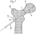
- FIG. 1 depicts upper portions of a femur with a femur neck fracture 1, and an outer bone fragment 2 and an inner bone fragment 3 on their respective sides of the fracture.
- a securing plate 4 which forms part of the device according to the present invention for fixation means in the form of bone screws or bone nails, in the version depicted two substantially parallel bone screws 5, 6 (see Figs.
- a guide wire 7 with a diameter of preferably about 2.4 mm has been drilled through the outer bone fragment 2 and into the inner bone fragment 3 under radioscopy and with guidance by a guide sleeve 8 with an inside diameter of preferably about 2.5 mm.
- the guide wire 7 is intended to guide a drill for drilling a hole for the bone screw 5 in the bone fragments 2, 3.
- the guide sleeve 8 for the guide wire 7 is applied in the securing plate 4, by preferably being screwed firmly in a threaded hole 9 running through the plate, and having for the purpose an externally threaded forward end portion 10 (see Fig. 2 depicting the guide sleeve 8 when it has been unscrewed from the plate 4).
- This externally threaded forward end portion 10 does of course have an outside diameter corresponding to the diameter of the threaded hole 9 in the securing plate 4, i.e. preferably about 9-10 mm.
- a second guide sleeve 11 with an inside diameter of preferably about 6.5 mm and an externally threaded forward portion with the same outside diameter as the first guide sleeve, is applied in, i.e. screwed into, the threaded hole 9 in the securing plate 4 ( Fig. 3 ).
- This guide sleeve 11 is intended to guide a drill 13, which has running through it a duct 12 for the wire guide 7 (see Figs. 5-10 ), for drilling the hole for the bone screw 5 in the bone fragments 2, 3.
- a gauge rod 14 is inserted at the rear of this guide sleeve and through the sleeve towards the bone 2, 3.
- the gauge rod 14 can be used in a conventional manner to indicate how far the drilling should go or how long the bone screw 5 should be for optimum function. In Fig. 4 the gauge rod 14 has been removed.
- the hole for the bone screw 5 can now be drilled. Accordingly, as illustrated in Fig. 5 , the drill 13 provided with the duct 12 is introduced through the guide sleeve 11 towards the bone fragment 2 and the drilling of the hole for the bone screw 5 is commenced, using a suitable drive device 15.
- the drill 13 has an outside diameter of preferably about 6.5 mm and fits exactly in the guide sleeve 11.
- the drill 13 is guided by the guide sleeve 11 to a correct position against the bone fragment 2 and thereafter by the guide wire 7 through the bone fragment 2 and past the fracture 1 into the bone fragment 3.
- Monitoring that the hole for the bone screw 5 is of a correct length is carried out with advantage at the rear of the guide sleeve 11, where the drill 13 or the drive device 15 bears suitable markings 16. This entails the drill 13 being halted about 2 cm from the tip of the guide wire 7, i.e. about 2 cm before reaching the point to which the bone screw 5 is intended to be screwed in.
- a further second guide sleeve 11 is now applied as per Fig. 6 in a second threaded hole 9 running through the plate.
- a guide sleeve 8 for a guide wire 7 may be applied first and the same procedure as before, with the same parts as above, may be carried out.
- guide sleeves of desired kinds 8, 11 may already from the outset be applied in the respective threaded holes 9 in the securing plate 4 to give the surgeon a better grasp for correct control of the guide wire 7 and the respective drills 13, 17.
- the guide sleeve 11 in the version depicted is intended to guide a drill 17 without a duct for the guide wire but with a conical tip (see Fig. 7 ).
- This solid drill 17 is driven in to a desired position for the bone screw 6 by means of the drive device 15.
- the correct length is read with advantage at the rear of the guide sleeve 11, where the drill 17 or the drive device 15 bears suitable markings 16 ( Fig. 7 ).
- the drill 17 and the guide sleeve 11 for it are removed ( Fig. 8 ), leaving a hole 18 for the bone screw 6 in the bone fragments 2, 3, which hole is shorter than the distance to which the bone screw is intended to be screwed in.
- the bone screw 6 can now, by means of a first fixing portion in the form of a threaded forward end portion 19, be screwed in through the free threaded hole 9 in the securing plate 4 (see Fig. 9 ) and into the hole 18 in the bone fragments 2, 3 in order to fix these bone fragments.
- the threaded forward end portion 19 of the bone screw 6 may be somewhat smaller and only be in contact with, i.e. ride on, the threads in the threaded hole 9 in the plate 4.
- the thread on the threaded forward end portion 19 of the bone screw 6 may be about 8 mm, while the thread in the threaded hole 9 in the securing plate 4 may, as previously indicated, be about 9-10 mm.
- the bone screw 6 is screwed in by using a suitable tool, in the version depicted a suitable type of screwdriver 20.
- a suitable tool in the version depicted a suitable type of screwdriver 20.
- the bone screw 6 is screwed in until the second fixing portion in the form of a threaded rear end portion 21 thereof engages in the threaded hole 9 in the securing plate 4 and locks the bone screw to the plate, while at the same time the threaded forward portion 19 of the bone screw is screwed through the outer bone fragment 2 and into the inner bone fragment 3 for engagement therein and locking of the latter bone fragment to the bone screw and the plate, and hence also of the outer bone fragment 2 between the plate and the inner bone fragment.
- the middle portion 22 of the bone screw 6, which is preferably unthreaded, has with advantage an outside diameter corresponding to that of the drill 17, i.e. about 6.5 mm. In Fig. 10 the bone screw 6 is fully screwed in.
- Fig. 11 the drill 13, the guide sleeve 11 for the drill, and the guide wire 7 have been removed.
- the bone screw 5, preferably similar in form to the bone screw 6, is screwed into the threaded hole 9 in the plate 4 freed by the removal of said items and into the hole 23 created by the drill 13 ( Fig. 10 ) in the bone fragments 2, 3 for fixation of the bone fragments.
- the bone screws 5, 6 are also configured, as a result of their smooth middle portion 22, to allow the bone fragments 2, 3 to be compressed so that the outer bone fragment 2 slides inwards away from the securing plate 4 towards the inner bone fragment 3 into which the bone screws are firmly screwed.
- the securing plate 4 will, through being locked to the bone screws 5, 6, move away from its abutment against the outer bone fragment 2 (this is represented schematically in Fig. 12 by the intermediate space 24 between the securing plate and the outer bone fragment), but without affecting the strength of the connection and without any impairment of function.
- Figs. 13 and 14 depict alternative versions of the securing plate 4.
- the securing plate 4 has in these versions three threaded holes 9 for bone screws.
- the threaded holes 9 for the bone screws run substantially parallel with one another so that the bone screws 5, 6 will likewise run substantially parallel with one another.
- Parallel running of the fixation means facilitates in particular the sliding movement of the outer bone fragment 2 along the fixation means (along the middle portion 22 thereof) for compression of the bone fragments.
- the securing plate 4 according to the present invention may be used not only for femur neck ( collum femoris ) fractures but also for, for example, upper arm ( humerus ) fractures.
- the device according to the invention also allows the application of guide sleeves for guidance of drills for drilling holes for the bone screws in the bone fragments, and/or guide sleeves for guidance of guide wires for said drills, in the same holes in the securing plate as are intended for the fixation means. This means that surgical staff need no longer keep count of an unnecessarily large number of different items for performing an operation, operating time becomes shorter and risks and complications for patients are reduced.
- the securing plate 4 may be used for guide sleeves 8 for guide wires and thereafter for guide sleeves 11 for drills or, for example, immediately for guide sleeves 11 for drills.
- the securing plate 4 may of course also be used only for guide sleeves 8 for guide wires, followed by drill guidance solely by guide wire, without special guide sleeves for drills.
- the securing plate 4 may also be used for bone screws of different kinds from the bone screws 5, 6 described above or for other types of fixation means, e.g. bone nails.
- a bone nail may have a sleeve and, disposed therein, a pin arranged for movement in the sleeve so that at least a forward portion of the pin can be driven outwards through at least one side aperture in the sleeve, in which case this forward portion constitutes a first fixing portion in the form of at least one hook which engages in the inner bone fragment, and the respective bone nail has in addition a second fixing portion of the type described above.
- the respective bone nail may also be so configured as to achieve engagement in the central portions of the inner bone fragment.
- the threads therein may be so disposed and/or configured that said result is achieved.
- Having the forward portion of the pin in the respective bone nail pointing towards the centre of the inner bone fragment not only means that the bone nails have a better grip in the inner bone fragment but also counteracts the risk of rotation or other movement of the bone nails.
- Said first and second fixing portions of the fixation means may also be other than threaded portions. The size and choice of material of the constituent items of an operating set may vary as necessary and desired.
Landscapes
- Health & Medical Sciences (AREA)
- Orthopedic Medicine & Surgery (AREA)
- Surgery (AREA)
- Life Sciences & Earth Sciences (AREA)
- Biomedical Technology (AREA)
- Public Health (AREA)
- Veterinary Medicine (AREA)
- Engineering & Computer Science (AREA)
- Nuclear Medicine, Radiotherapy & Molecular Imaging (AREA)
- Heart & Thoracic Surgery (AREA)
- Medical Informatics (AREA)
- Molecular Biology (AREA)
- Animal Behavior & Ethology (AREA)
- General Health & Medical Sciences (AREA)
- Neurology (AREA)
- Dentistry (AREA)
- Oral & Maxillofacial Surgery (AREA)
- Surgical Instruments (AREA)
Applications Claiming Priority (2)
| Application Number | Priority Date | Filing Date | Title |
|---|---|---|---|
| SE0701776A SE533303C2 (sv) | 2007-07-24 | 2007-07-24 | Anordning för fixering av benfragment vid benbrott |
| PCT/SE2008/050848 WO2009014485A1 (en) | 2007-07-24 | 2008-07-08 | Device for fixation of bone fragments at bone fractures |
Publications (3)
| Publication Number | Publication Date |
|---|---|
| EP2185089A1 EP2185089A1 (en) | 2010-05-19 |
| EP2185089A4 EP2185089A4 (en) | 2013-05-15 |
| EP2185089B1 true EP2185089B1 (en) | 2019-03-20 |
Family
ID=40281589
Family Applications (1)
| Application Number | Title | Priority Date | Filing Date |
|---|---|---|---|
| EP08779425.1A Active EP2185089B1 (en) | 2007-07-24 | 2008-07-08 | Device for fixation of bone fragments at bone fractures |
Country Status (6)
| Country | Link |
|---|---|
| US (2) | US9522025B2 (ja) |
| EP (1) | EP2185089B1 (ja) |
| JP (2) | JP5646321B2 (ja) |
| ES (1) | ES2726758T3 (ja) |
| SE (1) | SE533303C2 (ja) |
| WO (1) | WO2009014485A1 (ja) |
Families Citing this family (5)
| Publication number | Priority date | Publication date | Assignee | Title |
|---|---|---|---|---|
| EP2236101B1 (en) * | 2009-04-03 | 2015-07-08 | Stryker Trauma GmbH | Sonic screw |
| JP6270933B2 (ja) * | 2016-07-29 | 2018-01-31 | Kisco株式会社 | 大腿骨骨折用の治療器具及び固定プレート |
| CN109788960B (zh) * | 2016-08-15 | 2022-03-08 | 因奎创新有限责任公司 | 骨融合装置、系统和方法 |
| JP2018015574A (ja) * | 2017-08-23 | 2018-02-01 | Kisco株式会社 | 大腿骨骨折用の治療器具及び固定プレート |
| JP2018134499A (ja) * | 2018-06-04 | 2018-08-30 | スウェマック・イノヴェーション・アーベー | 骨折に際して骨片を固定する装置 |
Family Cites Families (35)
| Publication number | Priority date | Publication date | Assignee | Title |
|---|---|---|---|---|
| US2627855A (en) * | 1950-04-07 | 1953-02-10 | James W Price | Fracture nail and bone plate |
| SU1651778A3 (ru) * | 1986-12-19 | 1991-05-23 | Хута Баильдон, Пшедсембиорство Паньствове (Инопредприятие) | Устройство дл остеосинтеза переломов шейки бедренной кости |
| US4959064A (en) * | 1988-10-07 | 1990-09-25 | Boehringer Mannheim Corporation | Dynamic tension bone screw |
| JP3532622B2 (ja) * | 1993-03-28 | 2004-05-31 | ゴットフリード イェチエル | 経皮連結用の外科手術器具 |
| IL105183A (en) * | 1993-03-28 | 1996-07-23 | Yehiel Gotfried | Surgical device for connection of fractured bones |
| FR2711505B1 (fr) * | 1993-10-25 | 1995-12-29 | Tornier Sa | Dispositif de synthèse des fractures de l'extrémité supérieure du fémur. |
| JP3077049B2 (ja) * | 1994-11-01 | 2000-08-14 | 有限会社エーアンドエフ | 大腿骨頭回転骨切術及び大腿骨頸部骨折の治療用の内固定部材 |
| JP3949725B2 (ja) * | 1996-07-17 | 2007-07-25 | オーソーペディック デザインズ,インコーポレイティド | 外科用留め具組立体 |
| JPH10277052A (ja) * | 1997-04-02 | 1998-10-20 | For S Medical:Kk | 骨接合用スクリュー |
| DE19750493A1 (de) * | 1997-11-14 | 1999-06-02 | Medos Medizintechnik Gmbh | Implantat zur Stabilisierung einer Fraktur und Schraube zur Verwendung in der Chirurgie |
| US6019762A (en) * | 1998-04-30 | 2000-02-01 | Orthodyne, Inc. | Adjustable length orthopedic fixation device |
| EP1296603B1 (en) * | 2000-05-31 | 2006-05-17 | Vese, Silvana | Device for fixing a bone plate |
| JP3342472B2 (ja) * | 2000-07-21 | 2002-11-11 | 不二夫 川上 | 大腿骨頚部骨折骨接合手術用多孔状ガイド |
| US6306140B1 (en) | 2001-01-17 | 2001-10-23 | Synthes (Usa) | Bone screw |
| DE10129490A1 (de) | 2001-06-21 | 2003-01-02 | Helmut Mueckter | Implantierbare Schraube zur Stabilisierung einer Gelenkverbindung oder eines Knochenbruches |
| US20090131990A1 (en) | 2001-10-18 | 2009-05-21 | Kishore Tipirneni | Bone screw system and method |
| US20090254129A1 (en) | 2007-04-30 | 2009-10-08 | Kishore Tipirneni | Bone screw system and method for the fixation of bone fractures |
| US6736819B2 (en) | 2001-10-18 | 2004-05-18 | Kishore Tipirneni | System and method for fixation of bone fractures |
| JP4072750B2 (ja) * | 2002-01-18 | 2008-04-09 | 陽男 網代 | プロモータ具 |
| US7780710B2 (en) * | 2004-01-23 | 2010-08-24 | Depuy Products, Inc. | System for stabilization of fractures of convex articular bone surfaces including subchondral support structure |
| JP3722438B2 (ja) * | 2002-09-09 | 2005-11-30 | 株式会社フォーエスメディカル | 大腿骨頸部骨折治療用の内固定部材 |
| SE521951C2 (sv) * | 2002-12-04 | 2003-12-23 | Henrik Hansson | Anordning vid fixeringsorgan för fixering av benfragment vid benbrott |
| US7070601B2 (en) * | 2003-01-16 | 2006-07-04 | Triage Medical, Inc. | Locking plate for bone anchors |
| US7118572B2 (en) * | 2003-02-03 | 2006-10-10 | Orthopedic Designs, Inc. | Femoral neck compression screw system with ortho-biologic material delivery capability |
| US7135023B2 (en) | 2003-07-07 | 2006-11-14 | Watkins William T | Compression bone screw device |
| AU2005208810A1 (en) | 2004-01-23 | 2005-08-11 | Hand Innovations, Llc | System for stabilization of fractures of convex articular bone surfaces including subchondral support structure |
| US8172886B2 (en) | 2004-12-14 | 2012-05-08 | Depuy Products, Inc. | Bone plate with pre-assembled drill guide tips |
| US8197523B2 (en) | 2005-02-15 | 2012-06-12 | Apex Biomedical Company, Llc | Bone screw for positive locking but flexible engagement to a bone |
| US8740955B2 (en) | 2005-02-15 | 2014-06-03 | Zimmer, Inc. | Bone screw with multiple thread profiles for far cortical locking and flexible engagement to a bone |
| US20070055248A1 (en) * | 2005-07-29 | 2007-03-08 | Zlowodzki Michal P | Bone plating system for treatment of hip fractures |
| US8740903B2 (en) | 2006-02-09 | 2014-06-03 | DePuy Synthes Products, LLC | Method and apparatus for bone fracture fixation |
| US8398690B2 (en) | 2007-02-07 | 2013-03-19 | Apex Biomedical Company, Llc | Rotationally asymmetric bone screw |
| US20080275508A1 (en) * | 2007-05-04 | 2008-11-06 | Haidukewych George J | Bone end (epiphysis) fracture fixation device and method of use |
| US9615865B2 (en) | 2007-05-04 | 2017-04-11 | George J. Haidukewych | Bone end (epiphysis) fracture fixation device and method of use |
| US8551143B2 (en) * | 2011-10-11 | 2013-10-08 | Brent Lane Norris | Low profile periarticular tension band plating system with soft tissue neutralization cable tunnel/channel |
-
2007
- 2007-07-24 SE SE0701776A patent/SE533303C2/sv unknown
-
2008
- 2008-07-08 JP JP2010518147A patent/JP5646321B2/ja active Active
- 2008-07-08 WO PCT/SE2008/050848 patent/WO2009014485A1/en active Application Filing
- 2008-07-08 ES ES08779425T patent/ES2726758T3/es active Active
- 2008-07-08 US US12/670,156 patent/US9522025B2/en active Active
- 2008-07-08 EP EP08779425.1A patent/EP2185089B1/en active Active
-
2014
- 2014-07-04 JP JP2014138655A patent/JP6072732B2/ja active Active
-
2015
- 2015-05-19 US US14/715,825 patent/US9358052B2/en active Active
Non-Patent Citations (1)
| Title |
|---|
| None * |
Also Published As
| Publication number | Publication date |
|---|---|
| JP2014208282A (ja) | 2014-11-06 |
| WO2009014485A1 (en) | 2009-01-29 |
| US9358052B2 (en) | 2016-06-07 |
| US20150250511A1 (en) | 2015-09-10 |
| JP6072732B2 (ja) | 2017-02-01 |
| JP5646321B2 (ja) | 2014-12-24 |
| EP2185089A4 (en) | 2013-05-15 |
| EP2185089A1 (en) | 2010-05-19 |
| US20100211074A1 (en) | 2010-08-19 |
| ES2726758T3 (es) | 2019-10-09 |
| WO2009014485A9 (en) | 2009-09-03 |
| JP2010534107A (ja) | 2010-11-04 |
| SE0701776L (sv) | 2009-01-25 |
| SE533303C2 (sv) | 2010-08-17 |
| US9522025B2 (en) | 2016-12-20 |
Similar Documents
| Publication | Publication Date | Title |
|---|---|---|
| US9649118B2 (en) | Jig with guide adapted to lock relative to both of threaded holes and non-threaded slots in a bone plate | |
| US10111650B2 (en) | Pedicle mountable retractor system | |
| US7758582B2 (en) | Device and methods for placing external fixation elements | |
| US7004943B2 (en) | Devices, systems, and methods for placing and positioning fixation elements in external fixation systems | |
| EP1878394B1 (en) | Orthopaedic fixation plate having threaded guides | |
| US8696706B2 (en) | Percutaneous locking bone fixation system | |
| EP2575645B1 (en) | Surgical guide device | |
| US9358052B2 (en) | Method for fixation of bone fragments at bone fractures | |
| US20080119856A1 (en) | Intramedullary nail system and method for fixation of a fractured bone | |
| US20110137356A1 (en) | Bone compression device and methods | |
| US20220192723A1 (en) | Bone fracture fixation device with transverse set screw and aiming guide | |
| EP3466357B1 (en) | Systems intramedullary nail implantation | |
| EP2271274B1 (en) | Device for fixation of bone fragments at bone fractures | |
| US5152766A (en) | Femoral wire guide instrument | |
| US9642657B2 (en) | Device for fixation of bone fragments at bone fractures | |
| JP2011515186A5 (ja) | ||
| AU5198500A (en) | Inramedullary nail, in particular, intramedullary nail for the tibia | |
| WO2005082263A1 (en) | Device for fixation of femur fractures | |
| JP2020036996A (ja) | 骨折に際して骨片を固定する装置 | |
| RU70785U1 (ru) | Устройство для остеосинтеза шеечных, вертельных и подвертельных переломов бедренной кости | |
| CN107184248B (zh) | 植入体插入装置 | |
| WO2023086579A1 (en) | Interlocking screws for orthopedic surgery | |
| CA1177351A (en) | Surgical guide pin-external sleeve combination |
Legal Events
| Date | Code | Title | Description |
|---|---|---|---|
| PUAI | Public reference made under article 153(3) epc to a published international application that has entered the european phase |
Free format text: ORIGINAL CODE: 0009012 |
|
| 17P | Request for examination filed |
Effective date: 20100218 |
|
| AK | Designated contracting states |
Kind code of ref document: A1 Designated state(s): AT BE BG CH CY CZ DE DK EE ES FI FR GB GR HR HU IE IS IT LI LT LU LV MC MT NL NO PL PT RO SE SI SK TR |
|
| AX | Request for extension of the european patent |
Extension state: AL BA MK RS |
|
| DAX | Request for extension of the european patent (deleted) | ||
| A4 | Supplementary search report drawn up and despatched |
Effective date: 20130417 |
|
| RIC1 | Information provided on ipc code assigned before grant |
Ipc: A61B 17/68 20060101AFI20130411BHEP Ipc: A61B 17/74 20060101ALI20130411BHEP |
|
| STAA | Information on the status of an ep patent application or granted ep patent |
Free format text: STATUS: EXAMINATION IS IN PROGRESS |
|
| 17Q | First examination report despatched |
Effective date: 20161117 |
|
| GRAP | Despatch of communication of intention to grant a patent |
Free format text: ORIGINAL CODE: EPIDOSNIGR1 |
|
| STAA | Information on the status of an ep patent application or granted ep patent |
Free format text: STATUS: GRANT OF PATENT IS INTENDED |
|
| INTG | Intention to grant announced |
Effective date: 20181011 |
|
| GRAS | Grant fee paid |
Free format text: ORIGINAL CODE: EPIDOSNIGR3 |
|
| GRAA | (expected) grant |
Free format text: ORIGINAL CODE: 0009210 |
|
| STAA | Information on the status of an ep patent application or granted ep patent |
Free format text: STATUS: THE PATENT HAS BEEN GRANTED |
|
| AK | Designated contracting states |
Kind code of ref document: B1 Designated state(s): AT BE BG CH CY CZ DE DK EE ES FI FR GB GR HR HU IE IS IT LI LT LU LV MC MT NL NO PL PT RO SE SI SK TR |
|
| REG | Reference to a national code |
Ref country code: GB Ref legal event code: FG4D |
|
| REG | Reference to a national code |
Ref country code: CH Ref legal event code: EP |
|
| REG | Reference to a national code |
Ref country code: DE Ref legal event code: R096 Ref document number: 602008059433 Country of ref document: DE |
|
| REG | Reference to a national code |
Ref country code: AT Ref legal event code: REF Ref document number: 1109678 Country of ref document: AT Kind code of ref document: T Effective date: 20190415 |
|
| REG | Reference to a national code |
Ref country code: IE Ref legal event code: FG4D |
|
| REG | Reference to a national code |
Ref country code: NL Ref legal event code: FP |
|
| PG25 | Lapsed in a contracting state [announced via postgrant information from national office to epo] |
Ref country code: FI Free format text: LAPSE BECAUSE OF FAILURE TO SUBMIT A TRANSLATION OF THE DESCRIPTION OR TO PAY THE FEE WITHIN THE PRESCRIBED TIME-LIMIT Effective date: 20190320 Ref country code: SE Free format text: LAPSE BECAUSE OF FAILURE TO SUBMIT A TRANSLATION OF THE DESCRIPTION OR TO PAY THE FEE WITHIN THE PRESCRIBED TIME-LIMIT Effective date: 20190320 Ref country code: LT Free format text: LAPSE BECAUSE OF FAILURE TO SUBMIT A TRANSLATION OF THE DESCRIPTION OR TO PAY THE FEE WITHIN THE PRESCRIBED TIME-LIMIT Effective date: 20190320 Ref country code: NO Free format text: LAPSE BECAUSE OF FAILURE TO SUBMIT A TRANSLATION OF THE DESCRIPTION OR TO PAY THE FEE WITHIN THE PRESCRIBED TIME-LIMIT Effective date: 20190620 |
|
| REG | Reference to a national code |
Ref country code: LT Ref legal event code: MG4D |
|
| PG25 | Lapsed in a contracting state [announced via postgrant information from national office to epo] |
Ref country code: LV Free format text: LAPSE BECAUSE OF FAILURE TO SUBMIT A TRANSLATION OF THE DESCRIPTION OR TO PAY THE FEE WITHIN THE PRESCRIBED TIME-LIMIT Effective date: 20190320 Ref country code: HR Free format text: LAPSE BECAUSE OF FAILURE TO SUBMIT A TRANSLATION OF THE DESCRIPTION OR TO PAY THE FEE WITHIN THE PRESCRIBED TIME-LIMIT Effective date: 20190320 Ref country code: GR Free format text: LAPSE BECAUSE OF FAILURE TO SUBMIT A TRANSLATION OF THE DESCRIPTION OR TO PAY THE FEE WITHIN THE PRESCRIBED TIME-LIMIT Effective date: 20190621 Ref country code: BG Free format text: LAPSE BECAUSE OF FAILURE TO SUBMIT A TRANSLATION OF THE DESCRIPTION OR TO PAY THE FEE WITHIN THE PRESCRIBED TIME-LIMIT Effective date: 20190620 |
|
| REG | Reference to a national code |
Ref country code: AT Ref legal event code: MK05 Ref document number: 1109678 Country of ref document: AT Kind code of ref document: T Effective date: 20190320 |
|
| REG | Reference to a national code |
Ref country code: ES Ref legal event code: FG2A Ref document number: 2726758 Country of ref document: ES Kind code of ref document: T3 Effective date: 20191009 |
|
| PG25 | Lapsed in a contracting state [announced via postgrant information from national office to epo] |
Ref country code: EE Free format text: LAPSE BECAUSE OF FAILURE TO SUBMIT A TRANSLATION OF THE DESCRIPTION OR TO PAY THE FEE WITHIN THE PRESCRIBED TIME-LIMIT Effective date: 20190320 Ref country code: RO Free format text: LAPSE BECAUSE OF FAILURE TO SUBMIT A TRANSLATION OF THE DESCRIPTION OR TO PAY THE FEE WITHIN THE PRESCRIBED TIME-LIMIT Effective date: 20190320 Ref country code: CZ Free format text: LAPSE BECAUSE OF FAILURE TO SUBMIT A TRANSLATION OF THE DESCRIPTION OR TO PAY THE FEE WITHIN THE PRESCRIBED TIME-LIMIT Effective date: 20190320 Ref country code: PT Free format text: LAPSE BECAUSE OF FAILURE TO SUBMIT A TRANSLATION OF THE DESCRIPTION OR TO PAY THE FEE WITHIN THE PRESCRIBED TIME-LIMIT Effective date: 20190720 Ref country code: SK Free format text: LAPSE BECAUSE OF FAILURE TO SUBMIT A TRANSLATION OF THE DESCRIPTION OR TO PAY THE FEE WITHIN THE PRESCRIBED TIME-LIMIT Effective date: 20190320 |
|
| PG25 | Lapsed in a contracting state [announced via postgrant information from national office to epo] |
Ref country code: PL Free format text: LAPSE BECAUSE OF FAILURE TO SUBMIT A TRANSLATION OF THE DESCRIPTION OR TO PAY THE FEE WITHIN THE PRESCRIBED TIME-LIMIT Effective date: 20190320 |
|
| PG25 | Lapsed in a contracting state [announced via postgrant information from national office to epo] |
Ref country code: AT Free format text: LAPSE BECAUSE OF FAILURE TO SUBMIT A TRANSLATION OF THE DESCRIPTION OR TO PAY THE FEE WITHIN THE PRESCRIBED TIME-LIMIT Effective date: 20190320 Ref country code: IS Free format text: LAPSE BECAUSE OF FAILURE TO SUBMIT A TRANSLATION OF THE DESCRIPTION OR TO PAY THE FEE WITHIN THE PRESCRIBED TIME-LIMIT Effective date: 20190720 |
|
| REG | Reference to a national code |
Ref country code: DE Ref legal event code: R097 Ref document number: 602008059433 Country of ref document: DE |
|
| PLBE | No opposition filed within time limit |
Free format text: ORIGINAL CODE: 0009261 |
|
| STAA | Information on the status of an ep patent application or granted ep patent |
Free format text: STATUS: NO OPPOSITION FILED WITHIN TIME LIMIT |
|
| PG25 | Lapsed in a contracting state [announced via postgrant information from national office to epo] |
Ref country code: DK Free format text: LAPSE BECAUSE OF FAILURE TO SUBMIT A TRANSLATION OF THE DESCRIPTION OR TO PAY THE FEE WITHIN THE PRESCRIBED TIME-LIMIT Effective date: 20190320 |
|
| 26N | No opposition filed |
Effective date: 20200102 |
|
| PG25 | Lapsed in a contracting state [announced via postgrant information from national office to epo] |
Ref country code: SI Free format text: LAPSE BECAUSE OF FAILURE TO SUBMIT A TRANSLATION OF THE DESCRIPTION OR TO PAY THE FEE WITHIN THE PRESCRIBED TIME-LIMIT Effective date: 20190320 Ref country code: MC Free format text: LAPSE BECAUSE OF FAILURE TO SUBMIT A TRANSLATION OF THE DESCRIPTION OR TO PAY THE FEE WITHIN THE PRESCRIBED TIME-LIMIT Effective date: 20190320 |
|
| REG | Reference to a national code |
Ref country code: CH Ref legal event code: PL |
|
| PG25 | Lapsed in a contracting state [announced via postgrant information from national office to epo] |
Ref country code: TR Free format text: LAPSE BECAUSE OF FAILURE TO SUBMIT A TRANSLATION OF THE DESCRIPTION OR TO PAY THE FEE WITHIN THE PRESCRIBED TIME-LIMIT Effective date: 20190320 |
|
| REG | Reference to a national code |
Ref country code: BE Ref legal event code: MM Effective date: 20190731 |
|
| PG25 | Lapsed in a contracting state [announced via postgrant information from national office to epo] |
Ref country code: LU Free format text: LAPSE BECAUSE OF NON-PAYMENT OF DUE FEES Effective date: 20190708 Ref country code: BE Free format text: LAPSE BECAUSE OF NON-PAYMENT OF DUE FEES Effective date: 20190731 Ref country code: CH Free format text: LAPSE BECAUSE OF NON-PAYMENT OF DUE FEES Effective date: 20190731 Ref country code: LI Free format text: LAPSE BECAUSE OF NON-PAYMENT OF DUE FEES Effective date: 20190731 |
|
| PG25 | Lapsed in a contracting state [announced via postgrant information from national office to epo] |
Ref country code: FR Free format text: LAPSE BECAUSE OF NON-PAYMENT OF DUE FEES Effective date: 20190731 |
|
| PG25 | Lapsed in a contracting state [announced via postgrant information from national office to epo] |
Ref country code: IE Free format text: LAPSE BECAUSE OF NON-PAYMENT OF DUE FEES Effective date: 20190708 |
|
| PG25 | Lapsed in a contracting state [announced via postgrant information from national office to epo] |
Ref country code: CY Free format text: LAPSE BECAUSE OF FAILURE TO SUBMIT A TRANSLATION OF THE DESCRIPTION OR TO PAY THE FEE WITHIN THE PRESCRIBED TIME-LIMIT Effective date: 20190320 |
|
| PG25 | Lapsed in a contracting state [announced via postgrant information from national office to epo] |
Ref country code: MT Free format text: LAPSE BECAUSE OF FAILURE TO SUBMIT A TRANSLATION OF THE DESCRIPTION OR TO PAY THE FEE WITHIN THE PRESCRIBED TIME-LIMIT Effective date: 20190320 Ref country code: HU Free format text: LAPSE BECAUSE OF FAILURE TO SUBMIT A TRANSLATION OF THE DESCRIPTION OR TO PAY THE FEE WITHIN THE PRESCRIBED TIME-LIMIT; INVALID AB INITIO Effective date: 20080708 |
|
| PGFP | Annual fee paid to national office [announced via postgrant information from national office to epo] |
Ref country code: NL Payment date: 20230705 Year of fee payment: 16 |
|
| PGFP | Annual fee paid to national office [announced via postgrant information from national office to epo] |
Ref country code: IT Payment date: 20230710 Year of fee payment: 16 Ref country code: GB Payment date: 20230710 Year of fee payment: 16 |
|
| PGFP | Annual fee paid to national office [announced via postgrant information from national office to epo] |
Ref country code: DE Payment date: 20230705 Year of fee payment: 16 |
|
| PGFP | Annual fee paid to national office [announced via postgrant information from national office to epo] |
Ref country code: ES Payment date: 20231018 Year of fee payment: 16 |