EP2181920B1 - Hydraulische Steuerung für ein Schiffsgetriebe - Google Patents
Hydraulische Steuerung für ein Schiffsgetriebe Download PDFInfo
- Publication number
- EP2181920B1 EP2181920B1 EP09174111.6A EP09174111A EP2181920B1 EP 2181920 B1 EP2181920 B1 EP 2181920B1 EP 09174111 A EP09174111 A EP 09174111A EP 2181920 B1 EP2181920 B1 EP 2181920B1
- Authority
- EP
- European Patent Office
- Prior art keywords
- tool
- emergency
- hydraulic control
- pilot valve
- control arrangement
- Prior art date
- Legal status (The legal status is an assumption and is not a legal conclusion. Google has not performed a legal analysis and makes no representation as to the accuracy of the status listed.)
- Active
Links
Images
Classifications
-
- F—MECHANICAL ENGINEERING; LIGHTING; HEATING; WEAPONS; BLASTING
- F16—ENGINEERING ELEMENTS AND UNITS; GENERAL MEASURES FOR PRODUCING AND MAINTAINING EFFECTIVE FUNCTIONING OF MACHINES OR INSTALLATIONS; THERMAL INSULATION IN GENERAL
- F16K—VALVES; TAPS; COCKS; ACTUATING-FLOATS; DEVICES FOR VENTING OR AERATING
- F16K35/00—Means to prevent accidental or unauthorised actuation
- F16K35/06—Means to prevent accidental or unauthorised actuation using a removable actuating or locking member, e.g. a key
Definitions
- the present invention relates to a hydraulic control for a marine gear according to the closer defined in the preamble of claim 1. Art.
- Hydraulic controls for marine gearboxes are known.
- the hydraulic controls include valves that are electrically actuated during normal operation. These include, among other things, the pilot valves.
- the pilot valves In the case of a power failure, so in an emergency, it must still be possible to control the marine gearbox. Therefore, a manual mechanical emergency operation is required.
- the emergency operation by means of locking bolts, bayonet locks, locking screws or the like.
- Electrically actuated control valves with emergency operation are, for example EP-A-1 426 622 or off DE-U-200 23 901 known.
- the present invention is based on the object to propose a hydraulic control for a marine gear of the type described above, in which an unconscious manual emergency operation is not possible and which is also characterized by a user-friendly handling. This object is achieved by the features of claim 1. Further advantageous embodiments will become apparent from the dependent claims and the drawings.
- a hydraulic control or control device for a marine gear with at least one electrically operated pilot valve which comprises at least one emergency operating device for manually actuating the pilot valve, wherein the emergency operating device is actuated only with a tool.
- the tool may be used by an operator to deliberately actuate the emergency operator.
- the unconditional use of the tool prevents unintentional actuation of the emergency operating device by an operator.
- an actuating screw is used on the pilot valve as an emergency control device. This has the advantage that the emergency operation is activated until the operating screw is removed by the operator again.
- the tool for actuating the pilot valve can be arranged in the immediate vicinity of the pilot valve to be actuated.
- the tool is thus housed in an easily accessible location in close proximity to the valves, so that in an emergency, a quick operation of the pilot valve can be done by an operator.
- the emergency operation can also be easily understood and visualized.
- an additional plate can be attached to the pilot valve or the like and the emergency tool can be designated accordingly.
- the tool may be attached to the housing of the controller.
- other storage locations of the tool are conceivable.
- the tool is releasably secured in a threaded hole or the like of the housing of the controller.
- the tool In order to avoid loosening or loss of the tool, such as by vibrations during operation, the tool should be secured in a corresponding manner.
- Possible securing means are e.g. Spring washers against loosening the screw connection or a coupling of the tool with the control housing, e.g. by means of a chain.
- the tool may comprise a grip area, to which e.g. an elongated profile element or the like is provided with an external thread.
- the external thread serves to fasten in a corresponding internal thread in the threaded bore of the housing of the controller.
- an external polygon or the like can be provided on the profile element, in particular at its free end. With the external polygon of the tool, e.g. the actuating screw of the emergency operating device are actuated when it has a corresponding with the outer polygon socket. There are also other positive connections between the tool and the actuating screw possible.
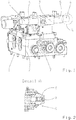
- FIG. 1 is exemplified a possible embodiment of a hydraulic control 1 for a marine gearbox shown.
- the controller 1 comprises a housing 2, on which a pilot valve 3 is arranged.
- the pilot valve 3 is electrically actuated by corresponding switching magnets 4 and 5 in normal operation.
- an emergency control device 6 is provided for the manual actuation of the pilot control valve 3.
- the emergency operating device 6 can be actuated with at least one tool 7. In this way, an unintentional operation is avoided because the operator always performs only a conscious operation due to the use of the tool 7.
- the actuating device 6 comprises an actuating screw 8.
- the actuating screw 8 is positively connected via a polygon socket 9 for actuation with the tool 7.
- the tool 7 is designed with a grip region 10 to which an elongated profile element 11 is fastened, at the free end of which an external polygon 12 is arranged.
- an operator with the outer polygon 12 engage in the polygon socket 9 of the actuating screw 8 and turn the actuating screw 8, so that the emergency operation is activated.
- the emergency control device is active until the actuating screw 8 is rotated back again by the operator.
- a hexagon are provided as outer polygon 12 and as polygon socket 9, respectively.
- the tool 7 is mounted in the immediate vicinity of the operated pilot valve 3 to the housing 2 of the controller.
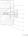
- the housing 2 has a threaded bore 13 into which the tool 7 can be screwed.
- the elongate profile element 11 of the tool 7 has an external thread which corresponds to the internal thread of the threaded bore 13.
- a backup of the tool 7 against loosening can be done for example by means of spring washers or a Spira-Lock thread and a polyamide stain coating.
Landscapes
- Engineering & Computer Science (AREA)
- General Engineering & Computer Science (AREA)
- Mechanical Engineering (AREA)
- Gear-Shifting Mechanisms (AREA)
- Fluid-Pressure Circuits (AREA)
Description
- Die vorliegende Erfindung betrifft eine hydraulische Steuerung für ein Schiffsgetriebe gemäß der im Oberbegriff des Patentanspruches 1 näher definierten Art.
- Hydraulische Steuerungen für Schiffsgetriebe sind bekannt. Üblicherweise umfassen die hydraulischen Steuerungen Ventile, die im Normalbetrieb elektrisch betätigt werden. Zu diesen zählen unter anderem auch die Vorsteuerventile. Im Fall eines Stromausfalles, also in einem Notfall, muss es dennoch möglich sein, das Schiffsgetriebe anzusteuern. Deshalb ist eine manuelle mechanische Notbetätigung erforderlich. Beispielsweise kann die Notbetätigung mittels Rastbolzen, Bajonettverschlüssen, Rastschrauben oder dergleichen erfolgen. Jedoch besteht bei dieser Art der Betätigung die Gefahr, dass eine unbewusste, ungewollte Betätigung durch den Bediener erfolgt, welches unbedingt zu vermeiden ist.
- Elektrisch betätigte Steuerventile mit Notbetätigungseinrichtung sind beispielsweise aus
EP-A-1 426 622 oder ausDE-U-200 23 901 bekannt. Der vorliegenden Erfindung liegt die Aufgabe zu Grunde, eine hydraulische Steuerung für ein Schiffsgetriebe der eingangs beschriebenen Gattung vorzuschlagen, bei der eine unbewusste manuelle Notbetätigung nicht möglich ist und die sich darüberhinaus durch eine bedienerfreundliche Handhabung auszeichnet. Diese Aufgabe wird erfindungsgemäß durch die Merkmale des Patentanspruches 1 gelöst. Weitere vorteilhafte Ausgestaltungen ergeben sich aus den Unteransprüchen und den Zeichnungen. - Die der Erfindung zu Grunde liegende Aufgabe wird durch eine hydraulische Steuerung bzw. Steuereinrichtung für ein Schiffsgetriebe mit zumindest einem elektrisch betätigten Vorsteuerventil gelöst, welches zumindest eine Notbetätigungseinrichtung zum manuellen Betätigen des Vorsteuerventils umfasst, wobei die Notbetätigungseinrichtung nur mit einem Werkzeug betätigbar ist.
- Beispielsweise bei einem Stromausfall kann so das Werkzeug von einem Bediener verwendet werden, um die Notbetätigungseinrichtung bewusst zu betätigen. Durch die unbedingte Verwendung des Werkzeuges wird ein unbeabsichtigtes Betätigen der Notbetätigungseinrichtung durch einen Bediener verhindert. Erfindungsgemäss wird eine Betätigungsschraube an dem Vorsteuerventil als Notbetätigungseinrichtung verwendet. Dies hat den Vorteil, dass die Notbetätigung solange aktiviert ist, bis die Betätigungsschraube von dem Bediener wieder entfernt wird.
- Mit besonderem Vorteil kann das Werkzeug zum Betätigen des Vorsteuerventils in unmittelbarer Nähe des zu betätigenden Vorsteuerventils angeordnet werden. Das Werkzeug ist somit an einer gut zugänglichen Stelle in unmittelbarer Nähe zu den Ventilen untergebracht, so dass im Notfall eine schnelle Bedienung des Vorsteuerventils durch einen Bediener erfolgen kann. Die Notbetätigung kann zum Beispiel auch einfach verständlich und bildlich dargestellt werden. Beispielsweise kann zu diesem Zweck ein zusätzliches Schild am Vorsteuerventil oder dergleichen angebracht werden und das Notwerkzeug entsprechend bezeichnet werden. Vorzugsweise kann das Werkzeug an dem Gehäuse der Steuerung befestigt sein. Es sind jedoch auch andere Lagerorte des Werkzeuges denkbar.
- Im Rahmen einer vorteilhaften Weiterbildung der Erfindung kann vorgesehen sein, dass das Werkzeug in einer Gewindebohrung oder dergleichen des Gehäuses der Steuerung lösbar befestigt ist. Durch diese Art der Befestigung werden einerseits eine bauraumsparende Unterbringung des Werkzeuges und andererseits eine schnelle Entnahme des Werkzeuges sichergestellt.
- Um ein Lösen bzw. einen Verlust des Werkzeuges, wie beispielsweise durch Schwingungen im Betrieb, zu vermeiden, sollte das Werkzeug in entsprechender Weise gesichert sein. Mögliche Sicherungsmittel sind z.B. Federringe gegen das Lösen der Schraubverbindung oder eine Koppelung des Werkzeuges mit dem Steuerungsgehäuse, z.B. mittels einer Kette.
- Vorzugsweise kann das Werkzeug einen Griffbereich umfassen, an dem z.B. ein längliches Profilelement oder dergleichen mit einem Außengewinde vorgesehen ist. Das Außengewinde dient dabei zum Befestigen in einem korrespondierenden Innengewinde in der Gewindebohrung des Gehäuses der Steuerung. Ferner kann an dem Profilelement insbesondere an seinem freien Ende ein Aussenmehrkant oder dergleichen vorgesehen sein. Mit dem Aussenmehrkant des Werkzeuges kann z.B. die Betätigungsschraube der Notbetätigungseinrichtung betätigt werden, wenn diese einen mit dem Aussenmehrkant korrespondierenden Innenmehrkant aufweist. Es sind auch andere formschlüssige Verbindungen zwischen dem Werkzeug und der Betätigungsschraube möglich.
- Im Weiteren wird die vorgeschlagene Erfindung anhand der Zeichnungen näher erläutert. Es zeigen:
-
Fig. 1 eine perspektivische Ansicht einer möglichen Ausführungsform einer erfindungsgemäßen hydraulischen Steuerung für ein Schiffsgetriebe; -
Fig. 2 eine vergrößerte Detailansicht gemäßFigur 1 ; und -
Fig. 3 eine geschnittene Teilansicht gemäßFigur 1 . - In
Figur 1 ist exemplarisch ein mögliches Ausführungsbeispiel für eine hydraulische Steuerung 1 für ein Schiffsgetriebe dargestellt. Die Steuerung 1 umfasst ein Gehäuse 2, auf dem ein Vorsteuerventil 3 angeordnet ist. Das Vorsteuerventil 3 wird im Normalbetrieb elektrisch durch entsprechende Schaltmagnete 4 und 5 betätigt. Um auch bei einem Stromausfall eine Betätigung des Vorsteuerventils 3 sicherzustellen, ist eine Notbetätigungseinrichtung 6 zum manuellen Betätigen des Vorsteuerventils 3 vorgesehen. - Erfindungsgemäß kann die Notbetätigungseinrichtung 6 mit zumindest einem Werkzeug 7 betätigt werden. Auf diese Weise wird eine unbeabsichtigte Betätigung vermieden, da der Bediener aufgrund der Benutzung des Werkzeuges 7 immer nur eine bewusste Betätigung durchführt.
- Wie insbesondere aus
Figur 2 ersichtlich ist, umfasst die Betätigungseinrichtung 6 eine Betätigungsschraube 8. Die Betätigungsschraube 8 ist über einen Innenmehrkant 9 zur Betätigung mit dem Werkzeug 7 formschlüssig verbindbar. Dazu ist das Werkzeug 7 mit einem Griffbereich 10 ausgeführt, an dem ein längliches Profilelement 11 befestigt ist, an dessen freien Ende ein Aussenmehrkant 12 angeordnet ist. Auf diese Weise kann ein Bediener mit dem Aussenmehrkant 12 in den Innenmehrkant 9 der Betätigungsschraube 8 eingreifen und die Betätigungsschraube 8 drehen, so dass die Notbetätigung aktiviert wird. Die Notbetätigungseinrichtung ist solange aktiv, bis die Betätigungsschraube 8 wieder von dem Bediener zurückgedreht wird. Vorzugsweise sind als Aussenmehrkant 12 und als Innenmehrkant 9 jeweils ein Sechskant vorgesehen. - Das Werkzeug 7 ist in unmittelbarer Nähe des zu betätigenden Vorsteuerventils 3 an dem Gehäuse 2 der Steuerung befestigt. Dazu weist das Gehäuse 2 eine Gewindebohrung 13 auf, in die das Werkzeug 7 einschraubbar ist. Das längliche Profilelement 11 des Werkzeuges 7 weist ein Außengewinde auf, welches mit dem Innengewinde der Gewindebohrung 13 korrespondiert. Auf diese Weise wird das Werkzeug 7 für die Notbetätigung bauraumsparend und in der Nähe des zu betätigenden Vorsteuerventils 3 gelagert, wie dies auch aus
Figur 1 ersichtlich ist. Eine Sicherung des Werkzeugs 7 gegen Losdrehen kann z.B. mittels Federringen oder einem Spira-Lock-Gewinde und einer Polyamid-Fleckbeschichtung erfolgen. -
- 1
- Steuerung
- 2
- Gehäuse
- 3
- Vorsteuerventil
- 4
- Schaltmagnet
- 5
- Schaltmagnet
- 6
- Notbetätigungseinrichtung
- 7
- Werkzeug
- 8
- Betätigungsschraube
- 9
- Innenmehrkant
- 10
- Griffbereich
- 11
- Profilelement
- 12
- Aussenmehrkant
- 13
- Gewindebohrung
Claims (6)
- Hydraulische Steuerung (1) für ein Schiffsgetriebe mit zumindest einem elektrisch betätigten Vorsteuerventil (3), welches eine Notbetätigungseinrichtung (6) zum manuellen Betätigen des Vorsteuerventils (3) umfasst, wobei die Notbetätigungseinrichtung (6) nur mit einem Werkzeug (7) betätigbar ist, dadurch gekennzeichnet, dass als Notbetätigungseinrichtung (6) eine Betätigungsschraube (8) an dem Vorsteuerventil (3) vorgesehen ist.
- Hydraulische Steuerungsanordnung mit einer hydraulischen Steuerung nach Anspruch 1 und mit einem Werkzeug zum Betätigen der Notbetägigungseinrichtung, dadurch gekennzeichnet, dass das Werkzeug (7) in unmittelbarer Nähe des zu betätigenden Vorsteuerventils (3) angeordnet ist.
- Hydraulische Steuerungsanordnung nach Anspruch 2, dadurch gek ennzeichnet, dass das Werkzeug (7) an dem Gehäuse (2) der Steuerung (1) befestigt ist.
- Hydraulische Steuerungsanordnung nach Anspruch 3, dadurch gek ennzeichnet, dass das Werkzeug (7) in einer Gewindebohrung (13) des Gehäuses (2) der Steuerung (1) lösbar befestigt ist.
- Hydraulische Steuerungsanordnung nach einem der Ansprüche 2 bis 4, dadurch gekennzeichnet, dass das Werkzeug (7) einen Griffbereich (10) umfasst, an dem ein Profilelement (11) mit einem Außengewinde vorgesehen ist, an dessen freien Ende ein Aussenmehrkant (12) angeordnet ist.
- Hydraulische Steuerungsanordnung nach Anspruch 5, dadurch gek ennzeichnet, dass die Betätigungsschraube (8) einen mit dem Aussenmehrkant (12) korrespondierenden Innenmehrkant (9) aufweist.
Applications Claiming Priority (1)
| Application Number | Priority Date | Filing Date | Title |
|---|---|---|---|
| DE102008043273A DE102008043273A1 (de) | 2008-10-29 | 2008-10-29 | Hydraulische Steuerung |
Publications (3)
| Publication Number | Publication Date |
|---|---|
| EP2181920A2 EP2181920A2 (de) | 2010-05-05 |
| EP2181920A3 EP2181920A3 (de) | 2014-03-26 |
| EP2181920B1 true EP2181920B1 (de) | 2018-04-04 |
Family
ID=41668472
Family Applications (1)
| Application Number | Title | Priority Date | Filing Date |
|---|---|---|---|
| EP09174111.6A Active EP2181920B1 (de) | 2008-10-29 | 2009-10-27 | Hydraulische Steuerung für ein Schiffsgetriebe |
Country Status (2)
| Country | Link |
|---|---|
| EP (1) | EP2181920B1 (de) |
| DE (1) | DE102008043273A1 (de) |
Family Cites Families (7)
| Publication number | Priority date | Publication date | Assignee | Title |
|---|---|---|---|---|
| US3957077A (en) * | 1975-05-12 | 1976-05-18 | The Dow Chemical Company | Valve and means for operating the valve |
| DE8813111U1 (de) * | 1988-10-19 | 1989-01-19 | Mannesmann Rexroth GmbH, 8770 Lohr | Vorsteuerventil |
| DE4009978A1 (de) * | 1989-04-04 | 1990-10-11 | Hoerbiger Hydraulik | Einrichtung zum betaetigen eines hydraulischen oder pneumatischen steuerventils |
| DE4110810A1 (de) * | 1991-01-26 | 1992-07-30 | Bosch Gmbh Robert | Pneumatische tuerbetaetigungsanlage fuer fahrzeuge |
| DE20023901U1 (de) * | 2000-06-30 | 2007-06-06 | Bosch Rexroth Aktiengesellschaft | Hydraulisches Ventil |
| DE10255454A1 (de) * | 2002-11-28 | 2004-06-09 | Tries Gmbh + Co. Kg | Steuerventil |
| DE102005005927A1 (de) * | 2005-02-09 | 2006-08-17 | Bosch Rexroth Aktiengesellschaft | Hydraulische Steueranordnung |
-
2008
- 2008-10-29 DE DE102008043273A patent/DE102008043273A1/de not_active Withdrawn
-
2009
- 2009-10-27 EP EP09174111.6A patent/EP2181920B1/de active Active
Non-Patent Citations (1)
| Title |
|---|
| None * |
Also Published As
| Publication number | Publication date |
|---|---|
| EP2181920A3 (de) | 2014-03-26 |
| EP2181920A2 (de) | 2010-05-05 |
| DE102008043273A1 (de) | 2010-05-06 |
Similar Documents
| Publication | Publication Date | Title |
|---|---|---|
| EP2028094B1 (de) | Betätigungsarmatur | |
| WO2004072496A1 (de) | Schraube mit integriertem schraubendreher | |
| DE102019111185A1 (de) | Spannvorrichtung für eine Schraubverbindung | |
| DE112013004907B4 (de) | Motorisierungseinheit für einen manuellen Tisch und manueller Tisch mit einer Motorisierungseinheit | |
| DE102013107096A1 (de) | Spannvorrichtung zum Dehnen eines Gewindebolzens | |
| EP3032093A1 (de) | Befestigungsvorrichtung zur befestigung eines rotorblattes an einer rotornabe einer windkraftanlage | |
| EP2896484A1 (de) | Auslösendes Drehmomentwerkzeug mit Stellvorrichtung | |
| DE102010008747A1 (de) | Vorrichtung zur Getriebenotentriegelung am Automatikgetriebe | |
| WO2017050725A1 (de) | Vorrichtung zur drehmomentbegrenzung | |
| EP2181920B1 (de) | Hydraulische Steuerung für ein Schiffsgetriebe | |
| EP3372343B1 (de) | Anordnung aus einem reaktionsmomente ableitenden stützarm und einem drehschrauber | |
| DE202010000021U1 (de) | Vorrichtung zur Montage und Demontage einer Fahrradkette | |
| EP0139808B1 (de) | Drehgriffarmatur zur Fernbetätigung von zwei oder mehreren Ablaufventilen in Spültischen, Waschtischen oder dergleichen | |
| DE202008014393U1 (de) | Hydraulische Steuerung | |
| WO2010063053A1 (de) | Vorrichtung zum auswechselbaren aufnehmen von werkzeugen | |
| DE19502855C2 (de) | Mundstück für ein Setzwerkzeug für Blindnietmuttern | |
| EP2704273A1 (de) | Befehls- und Meldegerät zur montage in eine Montagebohrung einer Montageplatte | |
| DE112018001786T5 (de) | Angetriebenes Werkzeug | |
| DE102010009070B4 (de) | Verbindungsanordnung zur Verbindung zweier Bauteile zur Verbindung eines Filtergehäuses mit einem Deckel sowie Vorrichtung mit der Verbindungsanordnung | |
| EP2039948A1 (de) | Montagehilfsmittel für Elektrodenstrang-Montage | |
| EP2236843B1 (de) | Anordnung, bestehend aus einer Schraube sowie einer an der Schraube befestigten Verliersicherung | |
| DE202004004530U1 (de) | Druckluftschraubervorrichtung | |
| DE102024100627A1 (de) | Spanneinrichtung für eine Sägekette eines Gartengeräts | |
| DE29918566U1 (de) | Sicherheitsverriegelung am Betätigungshebel für Betätigungseinrichtungen mit Federrückstellung | |
| DE102022120206A1 (de) | Einbaugarnitur mit Betätigungssicherung und Betätigungssicherung |
Legal Events
| Date | Code | Title | Description |
|---|---|---|---|
| PUAI | Public reference made under article 153(3) epc to a published international application that has entered the european phase |
Free format text: ORIGINAL CODE: 0009012 |
|
| AK | Designated contracting states |
Kind code of ref document: A2 Designated state(s): AT BE BG CH CY CZ DE DK EE ES FI FR GB GR HR HU IE IS IT LI LT LU LV MC MK MT NL NO PL PT RO SE SI SK SM TR |
|
| AX | Request for extension of the european patent |
Extension state: AL BA RS |
|
| PUAL | Search report despatched |
Free format text: ORIGINAL CODE: 0009013 |
|
| AK | Designated contracting states |
Kind code of ref document: A3 Designated state(s): AT BE BG CH CY CZ DE DK EE ES FI FR GB GR HR HU IE IS IT LI LT LU LV MC MK MT NL NO PL PT RO SE SI SK SM TR |
|
| AX | Request for extension of the european patent |
Extension state: AL BA RS |
|
| RIC1 | Information provided on ipc code assigned before grant |
Ipc: B63H 23/02 20060101AFI20140220BHEP Ipc: F16K 35/06 20060101ALI20140220BHEP |
|
| 17P | Request for examination filed |
Effective date: 20140516 |
|
| GRAP | Despatch of communication of intention to grant a patent |
Free format text: ORIGINAL CODE: EPIDOSNIGR1 |
|
| INTG | Intention to grant announced |
Effective date: 20171114 |
|
| RIN1 | Information on inventor provided before grant (corrected) |
Inventor name: STAMML, MICHAEL Inventor name: ROWE, GERALD Inventor name: SAGAWE, JOACHIM |
|
| GRAS | Grant fee paid |
Free format text: ORIGINAL CODE: EPIDOSNIGR3 |
|
| GRAA | (expected) grant |
Free format text: ORIGINAL CODE: 0009210 |
|
| AK | Designated contracting states |
Kind code of ref document: B1 Designated state(s): AT BE BG CH CY CZ DE DK EE ES FI FR GB GR HR HU IE IS IT LI LT LU LV MC MK MT NL NO PL PT RO SE SI SK SM TR |
|
| REG | Reference to a national code |
Ref country code: GB Ref legal event code: FG4D Free format text: NOT ENGLISH |
|
| REG | Reference to a national code |
Ref country code: CH Ref legal event code: EP |
|
| REG | Reference to a national code |
Ref country code: AT Ref legal event code: REF Ref document number: 985311 Country of ref document: AT Kind code of ref document: T Effective date: 20180415 |
|
| REG | Reference to a national code |
Ref country code: DE Ref legal event code: R096 Ref document number: 502009014863 Country of ref document: DE |
|
| REG | Reference to a national code |
Ref country code: IE Ref legal event code: FG4D Free format text: LANGUAGE OF EP DOCUMENT: GERMAN |
|
| REG | Reference to a national code |
Ref country code: NL Ref legal event code: MP Effective date: 20180404 |
|
| REG | Reference to a national code |
Ref country code: LT Ref legal event code: MG4D |
|
| REG | Reference to a national code |
Ref country code: FR Ref legal event code: PLFP Year of fee payment: 10 |
|
| PG25 | Lapsed in a contracting state [announced via postgrant information from national office to epo] |
Ref country code: NL Free format text: LAPSE BECAUSE OF FAILURE TO SUBMIT A TRANSLATION OF THE DESCRIPTION OR TO PAY THE FEE WITHIN THE PRESCRIBED TIME-LIMIT Effective date: 20180404 |
|
| PG25 | Lapsed in a contracting state [announced via postgrant information from national office to epo] |
Ref country code: ES Free format text: LAPSE BECAUSE OF FAILURE TO SUBMIT A TRANSLATION OF THE DESCRIPTION OR TO PAY THE FEE WITHIN THE PRESCRIBED TIME-LIMIT Effective date: 20180404 Ref country code: PL Free format text: LAPSE BECAUSE OF FAILURE TO SUBMIT A TRANSLATION OF THE DESCRIPTION OR TO PAY THE FEE WITHIN THE PRESCRIBED TIME-LIMIT Effective date: 20180404 Ref country code: NO Free format text: LAPSE BECAUSE OF FAILURE TO SUBMIT A TRANSLATION OF THE DESCRIPTION OR TO PAY THE FEE WITHIN THE PRESCRIBED TIME-LIMIT Effective date: 20180704 Ref country code: SE Free format text: LAPSE BECAUSE OF FAILURE TO SUBMIT A TRANSLATION OF THE DESCRIPTION OR TO PAY THE FEE WITHIN THE PRESCRIBED TIME-LIMIT Effective date: 20180404 Ref country code: BG Free format text: LAPSE BECAUSE OF FAILURE TO SUBMIT A TRANSLATION OF THE DESCRIPTION OR TO PAY THE FEE WITHIN THE PRESCRIBED TIME-LIMIT Effective date: 20180704 Ref country code: FI Free format text: LAPSE BECAUSE OF FAILURE TO SUBMIT A TRANSLATION OF THE DESCRIPTION OR TO PAY THE FEE WITHIN THE PRESCRIBED TIME-LIMIT Effective date: 20180404 Ref country code: LT Free format text: LAPSE BECAUSE OF FAILURE TO SUBMIT A TRANSLATION OF THE DESCRIPTION OR TO PAY THE FEE WITHIN THE PRESCRIBED TIME-LIMIT Effective date: 20180404 |
|
| PG25 | Lapsed in a contracting state [announced via postgrant information from national office to epo] |
Ref country code: GR Free format text: LAPSE BECAUSE OF FAILURE TO SUBMIT A TRANSLATION OF THE DESCRIPTION OR TO PAY THE FEE WITHIN THE PRESCRIBED TIME-LIMIT Effective date: 20180705 Ref country code: LV Free format text: LAPSE BECAUSE OF FAILURE TO SUBMIT A TRANSLATION OF THE DESCRIPTION OR TO PAY THE FEE WITHIN THE PRESCRIBED TIME-LIMIT Effective date: 20180404 Ref country code: HR Free format text: LAPSE BECAUSE OF FAILURE TO SUBMIT A TRANSLATION OF THE DESCRIPTION OR TO PAY THE FEE WITHIN THE PRESCRIBED TIME-LIMIT Effective date: 20180404 |
|
| PG25 | Lapsed in a contracting state [announced via postgrant information from national office to epo] |
Ref country code: PT Free format text: LAPSE BECAUSE OF FAILURE TO SUBMIT A TRANSLATION OF THE DESCRIPTION OR TO PAY THE FEE WITHIN THE PRESCRIBED TIME-LIMIT Effective date: 20180806 |
|
| REG | Reference to a national code |
Ref country code: DE Ref legal event code: R097 Ref document number: 502009014863 Country of ref document: DE |
|
| PG25 | Lapsed in a contracting state [announced via postgrant information from national office to epo] |
Ref country code: RO Free format text: LAPSE BECAUSE OF FAILURE TO SUBMIT A TRANSLATION OF THE DESCRIPTION OR TO PAY THE FEE WITHIN THE PRESCRIBED TIME-LIMIT Effective date: 20180404 Ref country code: CZ Free format text: LAPSE BECAUSE OF FAILURE TO SUBMIT A TRANSLATION OF THE DESCRIPTION OR TO PAY THE FEE WITHIN THE PRESCRIBED TIME-LIMIT Effective date: 20180404 Ref country code: DK Free format text: LAPSE BECAUSE OF FAILURE TO SUBMIT A TRANSLATION OF THE DESCRIPTION OR TO PAY THE FEE WITHIN THE PRESCRIBED TIME-LIMIT Effective date: 20180404 Ref country code: EE Free format text: LAPSE BECAUSE OF FAILURE TO SUBMIT A TRANSLATION OF THE DESCRIPTION OR TO PAY THE FEE WITHIN THE PRESCRIBED TIME-LIMIT Effective date: 20180404 Ref country code: SK Free format text: LAPSE BECAUSE OF FAILURE TO SUBMIT A TRANSLATION OF THE DESCRIPTION OR TO PAY THE FEE WITHIN THE PRESCRIBED TIME-LIMIT Effective date: 20180404 |
|
| PLBE | No opposition filed within time limit |
Free format text: ORIGINAL CODE: 0009261 |
|
| STAA | Information on the status of an ep patent application or granted ep patent |
Free format text: STATUS: NO OPPOSITION FILED WITHIN TIME LIMIT |
|
| PG25 | Lapsed in a contracting state [announced via postgrant information from national office to epo] |
Ref country code: SM Free format text: LAPSE BECAUSE OF FAILURE TO SUBMIT A TRANSLATION OF THE DESCRIPTION OR TO PAY THE FEE WITHIN THE PRESCRIBED TIME-LIMIT Effective date: 20180404 |
|
| 26N | No opposition filed |
Effective date: 20190107 |
|
| PG25 | Lapsed in a contracting state [announced via postgrant information from national office to epo] |
Ref country code: SI Free format text: LAPSE BECAUSE OF FAILURE TO SUBMIT A TRANSLATION OF THE DESCRIPTION OR TO PAY THE FEE WITHIN THE PRESCRIBED TIME-LIMIT Effective date: 20180404 |
|
| REG | Reference to a national code |
Ref country code: CH Ref legal event code: PL |
|
| PG25 | Lapsed in a contracting state [announced via postgrant information from national office to epo] |
Ref country code: LU Free format text: LAPSE BECAUSE OF NON-PAYMENT OF DUE FEES Effective date: 20181027 Ref country code: MC Free format text: LAPSE BECAUSE OF FAILURE TO SUBMIT A TRANSLATION OF THE DESCRIPTION OR TO PAY THE FEE WITHIN THE PRESCRIBED TIME-LIMIT Effective date: 20180404 |
|
| REG | Reference to a national code |
Ref country code: IE Ref legal event code: MM4A |
|
| PG25 | Lapsed in a contracting state [announced via postgrant information from national office to epo] |
Ref country code: CH Free format text: LAPSE BECAUSE OF NON-PAYMENT OF DUE FEES Effective date: 20181031 Ref country code: LI Free format text: LAPSE BECAUSE OF NON-PAYMENT OF DUE FEES Effective date: 20181031 |
|
| PG25 | Lapsed in a contracting state [announced via postgrant information from national office to epo] |
Ref country code: IE Free format text: LAPSE BECAUSE OF NON-PAYMENT OF DUE FEES Effective date: 20181027 |
|
| REG | Reference to a national code |
Ref country code: AT Ref legal event code: MM01 Ref document number: 985311 Country of ref document: AT Kind code of ref document: T Effective date: 20181027 |
|
| PG25 | Lapsed in a contracting state [announced via postgrant information from national office to epo] |
Ref country code: AT Free format text: LAPSE BECAUSE OF NON-PAYMENT OF DUE FEES Effective date: 20181027 Ref country code: MT Free format text: LAPSE BECAUSE OF FAILURE TO SUBMIT A TRANSLATION OF THE DESCRIPTION OR TO PAY THE FEE WITHIN THE PRESCRIBED TIME-LIMIT Effective date: 20180404 |
|
| PG25 | Lapsed in a contracting state [announced via postgrant information from national office to epo] |
Ref country code: TR Free format text: LAPSE BECAUSE OF FAILURE TO SUBMIT A TRANSLATION OF THE DESCRIPTION OR TO PAY THE FEE WITHIN THE PRESCRIBED TIME-LIMIT Effective date: 20180404 |
|
| PG25 | Lapsed in a contracting state [announced via postgrant information from national office to epo] |
Ref country code: HU Free format text: LAPSE BECAUSE OF FAILURE TO SUBMIT A TRANSLATION OF THE DESCRIPTION OR TO PAY THE FEE WITHIN THE PRESCRIBED TIME-LIMIT; INVALID AB INITIO Effective date: 20091027 Ref country code: CY Free format text: LAPSE BECAUSE OF FAILURE TO SUBMIT A TRANSLATION OF THE DESCRIPTION OR TO PAY THE FEE WITHIN THE PRESCRIBED TIME-LIMIT Effective date: 20180404 Ref country code: MK Free format text: LAPSE BECAUSE OF NON-PAYMENT OF DUE FEES Effective date: 20180404 |
|
| PG25 | Lapsed in a contracting state [announced via postgrant information from national office to epo] |
Ref country code: IS Free format text: LAPSE BECAUSE OF FAILURE TO SUBMIT A TRANSLATION OF THE DESCRIPTION OR TO PAY THE FEE WITHIN THE PRESCRIBED TIME-LIMIT Effective date: 20180804 |
|
| P01 | Opt-out of the competence of the unified patent court (upc) registered |
Effective date: 20230528 |
|
| PGFP | Annual fee paid to national office [announced via postgrant information from national office to epo] |
Ref country code: IT Payment date: 20230913 Year of fee payment: 15 Ref country code: GB Payment date: 20230907 Year of fee payment: 15 |
|
| PGFP | Annual fee paid to national office [announced via postgrant information from national office to epo] |
Ref country code: FR Payment date: 20230911 Year of fee payment: 15 |
|
| GBPC | Gb: european patent ceased through non-payment of renewal fee |
Effective date: 20241027 |
|
| PG25 | Lapsed in a contracting state [announced via postgrant information from national office to epo] |
Ref country code: GB Free format text: LAPSE BECAUSE OF NON-PAYMENT OF DUE FEES Effective date: 20241027 |
|
| PG25 | Lapsed in a contracting state [announced via postgrant information from national office to epo] |
Ref country code: FR Free format text: LAPSE BECAUSE OF NON-PAYMENT OF DUE FEES Effective date: 20241031 |
|
| PG25 | Lapsed in a contracting state [announced via postgrant information from national office to epo] |
Ref country code: IT Free format text: LAPSE BECAUSE OF NON-PAYMENT OF DUE FEES Effective date: 20241027 |
|
| PGFP | Annual fee paid to national office [announced via postgrant information from national office to epo] |
Ref country code: BE Payment date: 20250917 Year of fee payment: 17 |
|
| PGFP | Annual fee paid to national office [announced via postgrant information from national office to epo] |
Ref country code: DE Payment date: 20250902 Year of fee payment: 17 |