EP1426622A2 - Steuerventil - Google Patents
Steuerventil Download PDFInfo
- Publication number
- EP1426622A2 EP1426622A2 EP03024674A EP03024674A EP1426622A2 EP 1426622 A2 EP1426622 A2 EP 1426622A2 EP 03024674 A EP03024674 A EP 03024674A EP 03024674 A EP03024674 A EP 03024674A EP 1426622 A2 EP1426622 A2 EP 1426622A2
- Authority
- EP
- European Patent Office
- Prior art keywords
- control valve
- control
- piston
- valve according
- pilot piston
- Prior art date
- Legal status (The legal status is an assumption and is not a legal conclusion. Google has not performed a legal analysis and makes no representation as to the accuracy of the status listed.)
- Granted
Links
Images
Classifications
-
- F—MECHANICAL ENGINEERING; LIGHTING; HEATING; WEAPONS; BLASTING
- F16—ENGINEERING ELEMENTS AND UNITS; GENERAL MEASURES FOR PRODUCING AND MAINTAINING EFFECTIVE FUNCTIONING OF MACHINES OR INSTALLATIONS; THERMAL INSULATION IN GENERAL
- F16K—VALVES; TAPS; COCKS; ACTUATING-FLOATS; DEVICES FOR VENTING OR AERATING
- F16K11/00—Multiple-way valves, e.g. mixing valves; Pipe fittings incorporating such valves
- F16K11/02—Multiple-way valves, e.g. mixing valves; Pipe fittings incorporating such valves with all movable sealing faces moving as one unit
- F16K11/06—Multiple-way valves, e.g. mixing valves; Pipe fittings incorporating such valves with all movable sealing faces moving as one unit comprising only sliding valves, i.e. sliding closure elements
- F16K11/065—Multiple-way valves, e.g. mixing valves; Pipe fittings incorporating such valves with all movable sealing faces moving as one unit comprising only sliding valves, i.e. sliding closure elements with linearly sliding closure members
- F16K11/07—Multiple-way valves, e.g. mixing valves; Pipe fittings incorporating such valves with all movable sealing faces moving as one unit comprising only sliding valves, i.e. sliding closure elements with linearly sliding closure members with cylindrical slides
-
- F—MECHANICAL ENGINEERING; LIGHTING; HEATING; WEAPONS; BLASTING
- F15—FLUID-PRESSURE ACTUATORS; HYDRAULICS OR PNEUMATICS IN GENERAL
- F15B—SYSTEMS ACTING BY MEANS OF FLUIDS IN GENERAL; FLUID-PRESSURE ACTUATORS, e.g. SERVOMOTORS; DETAILS OF FLUID-PRESSURE SYSTEMS, NOT OTHERWISE PROVIDED FOR
- F15B13/00—Details of servomotor systems ; Valves for servomotor systems
- F15B13/02—Fluid distribution or supply devices characterised by their adaptation to the control of servomotors
- F15B13/04—Fluid distribution or supply devices characterised by their adaptation to the control of servomotors for use with a single servomotor
- F15B13/0401—Valve members; Fluid interconnections therefor
- F15B13/0402—Valve members; Fluid interconnections therefor for linearly sliding valves, e.g. spool valves
- F15B13/0403—Valve members; Fluid interconnections therefor for linearly sliding valves, e.g. spool valves a secondary valve member sliding within the main spool, e.g. for regeneration flow
-
- F—MECHANICAL ENGINEERING; LIGHTING; HEATING; WEAPONS; BLASTING
- F15—FLUID-PRESSURE ACTUATORS; HYDRAULICS OR PNEUMATICS IN GENERAL
- F15B—SYSTEMS ACTING BY MEANS OF FLUIDS IN GENERAL; FLUID-PRESSURE ACTUATORS, e.g. SERVOMOTORS; DETAILS OF FLUID-PRESSURE SYSTEMS, NOT OTHERWISE PROVIDED FOR
- F15B13/00—Details of servomotor systems ; Valves for servomotor systems
- F15B13/02—Fluid distribution or supply devices characterised by their adaptation to the control of servomotors
- F15B13/04—Fluid distribution or supply devices characterised by their adaptation to the control of servomotors for use with a single servomotor
- F15B13/042—Fluid distribution or supply devices characterised by their adaptation to the control of servomotors for use with a single servomotor operated by fluid pressure
- F15B13/043—Fluid distribution or supply devices characterised by their adaptation to the control of servomotors for use with a single servomotor operated by fluid pressure with electrically-controlled pilot valves
- F15B13/0435—Fluid distribution or supply devices characterised by their adaptation to the control of servomotors for use with a single servomotor operated by fluid pressure with electrically-controlled pilot valves the pilot valves being sliding valves
-
- F—MECHANICAL ENGINEERING; LIGHTING; HEATING; WEAPONS; BLASTING
- F16—ENGINEERING ELEMENTS AND UNITS; GENERAL MEASURES FOR PRODUCING AND MAINTAINING EFFECTIVE FUNCTIONING OF MACHINES OR INSTALLATIONS; THERMAL INSULATION IN GENERAL
- F16K—VALVES; TAPS; COCKS; ACTUATING-FLOATS; DEVICES FOR VENTING OR AERATING
- F16K31/00—Actuating devices; Operating means; Releasing devices
- F16K31/02—Actuating devices; Operating means; Releasing devices electric; magnetic
- F16K31/04—Actuating devices; Operating means; Releasing devices electric; magnetic using a motor
Definitions
- the invention relates to a control valve according to the preamble of claim 1.
- Control valves are in hydraulic or pneumatic Systems for controlling drive units and / or Control elements used.
- servo valves are commercially available used where an electrically controllable Pilot valve is used to make a main control valve actuate.
- the working pressure of the pilot valve is here usually lower than the high working pressure of the Main control valve, so here elements for Pressure reduction for the pilot valve are required.
- an arrangement has already become known which is a pilot valve inside the main control valve is arranged. This is realized by the piston of the pilot valve together with the corresponding Fluid chambers for actuating the pilot valve inside a valve piston of the main control valve can be arranged.
- the known commercially available device is included an electric motor or a so-called torque motor provided the one via an intermediate gear and a spindle Control rod that moves with the pilot piston connected is.
- This version has the advantage that both valves, the Pilot valve and the main control valve with the same Working pressure, but it is due to the elaborate mechanical structure between electric motor and Pilot spool comparatively expensive and above also prone to wear and failure.
- the object of the invention is compared to this state of the Technology to propose a control valve that without Pressure reduction for the pilot valve can work with little effort to make and moreover little is prone to wear and failure.
- This task is based on a device according to the Preamble of claim 1 by its characterizing Features solved.
- Control valve characterized in that as a drive unit so-called linear motor is provided.
- a linear motor can be realized, for example, by using an anchor a permanent magnet inside a coil axially is slidably arranged.
- By suitable control of the This armature is coiled by the appropriate magnetic field brought a defined position.
- Such a device which works on the so-called "voice coil” principle, can work without contact and therefore extremely wear-resistant.
- Such a linear motor is preferred in the axial Extension of the pilot piston arranged. hereby results in a compact, space-saving unit that it enables both the linear motor and the Pilot spool along the same geometric axis to arrange slidably.
- the Linear motor mechanically directly with the pilot piston coupled. Especially when armature and pilot spool slidable along a common geometric axis such a direct mechanical coupling is special easy to implement.
- the anchor in the form of a control rod is preferred trained that carries a permanent magnet.
- the control rod should consist of one non-magnetic material, so that due to the defined magnetic field of the permanent magnet the position the armature by controlling the control coil accordingly can be set reliably.
- Such a control rod can be axial aligned arrangement with the pilot piston directly with be connected to it.
- Emergency actuation with the help of an emergency actuation element intended.
- Such an emergency actuation makes sense in order to In the event of a failure of the electrical control, for example as a result of a power failure or Defect the system controlled by the control valve to keep it functional at least to a limited extent.
- Such an emergency actuation element can, for example, directly attack the pilot spool and serve the Manually move the pilot piston.
- a Emergency actuator on the pilot spool opposite side of the linear motor arranged.
- This Arrangement offers the advantage of good accessibility from outside and also leaves the linear motor opposite end of the pilot piston for the Arrangement of further valve components free.
- the Anchor designed and arranged so that it is directly connected to the emergency operating element is displaceable.
- a correspondingly long version of the control rod be realized on which the permanent magnet is arranged is that this is inside the control coil that Control rod, however, from the front of the control coil is accessible.
- the latter embodiment offers the advantage that the emergency actuation element to be actuated from outside can be arranged at a distance from the magnet armature or the control rod during normal operation.
- the seal of the externally accessible emergency actuating element against the housing wall of the control valve is thus static in normal operation.
- a static seal is always less complex and easier to keep permanently sealed compared to a dynamic seal that would be required if the emergency actuating element penetrating the wall carried out every movement of the control piston in normal operation.
- an emergency manual actuating element is also provided on the side of the pilot piston opposite the linear motor. This is particularly advantageous if the first-mentioned manual override element is spaced from the pilot piston and is therefore provided mechanically decoupled from it in normal operation.
- the function of the emergency manual control if it is carried out from one side in each case by pressing the respective manual manual control element onto the control rod or the pilot piston. This can be done mechanically with the aid of an auxiliary tool that can be inserted into the valve housing.
- a Position or displacement sensor provided for the pilot spool.
- a sensor for example on the linear motor arranged opposite end of the pilot piston become. This is an exact setting of the Pilot spool position possible by capturing and to Feedback is used. With the help of a control loop the pilot spool can then be moved to the desired position be regulated. In addition, with the help of a such a sensor system detects a defective control valve and appearing by an incorrect position of the pilot piston results.
- An arrangement according to the invention is so easy realize that the pilot valve or the Pilot piston the full working pressure of the hydraulic system or machine switches and thus to control the Main control valve uses. As already mentioned at the beginning, this eliminates the need for pressure reduction and accordingly the effort required for this.
- the zero or neutral position of the main spool will preferably set via spring elements.
- the spring elements can be fixed the zero position can also be dimensioned stronger. This will zero the position without pressurizing the Main control piston ingested quickly and reliably.
- stronger springs for the zero point setting allows larger spring tolerances be, which further reduces the effort.
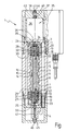
- the only figure shows a control valve according to the invention in Longitudinal section.
- the control valve 1 comprises a valve housing 2, the with a first and a second shield 3 on both sides, 4 is provided.
- valve housing 1 Inside the valve housing 1 are not detailed fluid lines shown provided to the fluid, for example, hydraulic oil to the function corresponding areas on the pilot piston and the Main control piston to feed or discharge.
- the external connections are also not shown.
- a pilot piston 5 is axially centered inside one Main control piston 6 is arranged axially displaceable.
- annular fluid chambers 7 are arranged which Ring projections 8 or in between Cross-sectional tapering 9 of the main control piston 6 depending on the axial position of the main control piston 6 with each other connected or disconnected from each other.
- the supply line or derivation to the fluid chambers 7 is not described in detail shown holes in the valve housing 2 accomplished.
- the main control piston 6 has two end faces Control chambers 10, 11 by pressurizing using the corresponding fluids, e.g. Hydraulic oil in the axial direction controlled sliding.
- corresponding fluids e.g. Hydraulic oil in the axial direction controlled sliding.
- the centering of the main spool is over two Spring elements, for example spiral springs 12, 13 in the Control chambers 10, 11 accomplished.
- the pressurization the control chambers 10, 11 is about the position of the Pilot piston 5 made.
- the pilot piston 5 has an area in the middle compared to the inner diameter of the main control piston 6 reduced diameter, so that between the Pilot piston 5 and the main control piston 6 along the A fluid connection 14 to the outer circumference of the pilot piston 5 the end regions of the pilot piston 5 on both sides pressurized fluid, such as hydraulic oil results.
- the inflow results from holes 15 in the Main control piston 6, which is connected to the pressure-side fluid supply 16 of the control valve is connected.
- the fluid connection 14 is in the end regions with two channels 17, 18 arranged within the pilot piston 5 connected, which in turn each have a connection opening 19, 20 on the outer circumference of the pilot piston 5.
- the area corresponds to the outer circumference of the pilot piston 5 Inner circumference of the main control piston 6.
- the connection openings 19, 20 are one Connection opening 21, 22 in the main control piston 6 opposite or the connection openings 19, 20 are as in illustrated example through the inner wall of the Main control piston 6 closed.
- connection openings 21, 22 in the corresponding position of the pilot piston 5 a Connection between the fluid supply 16 via the bore 15 and the fluid connection 14 to the control chambers 10, 11 are manufactured.
- the main control piston 6 is in its end regions form-fitting to end sleeves 23, 24.
- the in axial Extension to the main control piston 6 cavities inside the end sleeves 23, 24 serve to collect any leak oil. In a way, they form leakage oil chambers 25, 26, in a manner not shown with a Fluid supply, e.g. are connected to a hydraulic oil tank. Consequently, the leak oil chambers 25, 26 are always depressurized.
- the pilot piston 5 has channels 27, 28 on the end face, the on the outer circumference of the pilot piston 5 with Connection openings 29, 30 are connected. Channels 27, 28 are on the end face via a side channel 33 or Axial bore 34 connected to the leak oil chambers 25, 26. ever according to the position of the pilot piston 5 Connection openings 29, 30 in front of connection openings 31, 32, which in turn are connected to the control chambers 10, 11, or the connection openings 29, 30 are as in illustrated case through the inner wall of the Main control piston 6 closed.
- the linear motor 35 includes a control coil 36 within which one is not closer shown magnet armature is arranged axially displaceable.
- the magnet armature includes one from the control coil 36 in FIG drawn illustration of hidden permanent magnet, the a control rod 37 is attached.
- the control rod 37 is provided with a central through hole 38 and over one inserted into the pilot piston 5 at the end Coupling sleeve 39 is tension and pressure resistant with the pilot piston 5 connected.
- the control rod 37 sits just like that Leakage oil chamber 26 to the opposite side of the Control coil 36 continues where it with its through hole 38 in the end region 40 of the leak oil chamber 26 opens.
- the other Leakage oil chamber 25 is on the side channel 33 with the associated leakage oil chamber 25 in connection.
- the valve In the position shown, the valve is in its neutral position.
- the pilot piston is in a position in of all connection openings 19, 20 and 29, 30 through the Inner wall of the main control piston 6 are closed. This means due to the following It also works that the pressure in both control chambers 10, 11 is balanced, so that the main control piston 6 due to the coil springs 12, 13 in its central position is held.
- the pilot piston with the help of the linear motor 36 For example, moved away from the linear motor 36, the Control chamber 11 via the connection opening 20 with pressure applied.
- the control chamber 10 via the connection opening 29 and the Connection opening 31 with the unpressurized leak oil chamber 25 connected. This causes the main spool 6 from Linear motor 36 is moved away.
- the desired one Control function of the valve via the ring projections 8 and Cross-sectional tapers 9 and the various Fluid chambers 7 made by different fluid chambers 7 connected or separated from each other.
- the main control piston 6 can move in a defined position of the pilot piston 5 until the Connection opening 20 again through the inner wall of the Main control piston 6 is closed and at the same time the Outflow from the control chamber 10 via the connection opening 29 is also prevented by the connection opening 29 in turn through the inner wall of the main control piston 6 is closed.
- Position sensor 41 On the side opposite the linear motor 35 is a Position sensor 41 attached, the details of which are not is shown in more detail.
- the specific design of the Displacement transducer is for use in the invention of of minor importance. Basically, all types are used by displacement sensors 41 which have the corresponding Have dimensions and parameters.
- the leak oil chamber 26 is closed with a sealing element 43 is closed.
- the sealing element 43 can be axial Direction can be arranged. Over a Access opening 44 allows the sealing element 43 to the inside be pushed in until it strikes the control rod 37. For this purpose, there is only a corresponding rod-shaped one Auxiliary tool (not shown in detail) required. By pressing in the control rod 37, a Emergency manual operation of the control valve according to the invention in a Direction are triggered.
- a comparable sealing element 45 On the opposite side is a comparable sealing element 45, which has an access opening 46 is accessible.
- the sealing element 45 On the opposite side is a comparable sealing element 45, which has an access opening 46 is accessible.
- the control valve according to the invention allows switching the full hydraulic working pressure on the control chambers 10 and 11 and thus on the main control piston 6 using the Pilot piston 5. This gives a short response time of the main control piston 6 guaranteed. Beyond that a reliable and stable clamping of the Main control piston 6 in the desired position realizable.
- Linear motor for example according to the so-called “Voice coil” principle, as described in the exemplary embodiment.
- the magnet armature with control rod 37 can be almost contactless and thus guided within the control coil 36 without wear become.
- arrangement of the Linear motor 35 in axial extension to the pilot piston 5 a very simple and fail-safe Connection possibility between the magnet armature or the Control rod 37 and the pilot piston 5.
Landscapes
- Engineering & Computer Science (AREA)
- General Engineering & Computer Science (AREA)
- Mechanical Engineering (AREA)
- Physics & Mathematics (AREA)
- Fluid Mechanics (AREA)
- Servomotors (AREA)
- Valve Device For Special Equipments (AREA)
- Fluid-Driven Valves (AREA)
- Lift Valve (AREA)
- Magnetically Actuated Valves (AREA)
- Actuator (AREA)
Abstract
Description
In einer besonderen Ausführung wird auf der dem Linearmotor gegenüberliegenden Seite des Vorsteuerkolbens ebenfalls ein Nothandbetätigungselement vorgesehen. Dies ist insbesondere dann von Vorteil, wenn das erstgenannte Nothandbetätigungselement vom Vorsteuerkolben beabstandet und somit von diesem im Normalbetrieb mechanisch entkoppelt vorgesehen wird. In diesem Fall genügt es für die Funktion der Nothandbetätigung, wenn diese jeweils von einer Seite her durch Drücken mittels dem jeweiligen Nothandbetätigungselement auf die Steuerstange bzw. den Vorsteuerkolben erfolgt. Dies kann mechanisch mit Hilfe eines in das Ventilgehäuse einführbaren Hilfswerkzeugs vorgenommen werden.
- 1
- Steuerventil
- 2
- Ventilgehäuse
- 3
- Abschirmung
- 4
- Abschirmung
- 5
- Vorsteuerkolben
- 6
- Hauptsteuerkolben
- 7
- Fluidkammern
- 8
- Ringvorsprung
- 9
- Querschnittsverjüngung
- 10
- Steuerkammer
- 11
- Steuerkammer
- 12
- Spiralfeder
- 13
- Spiralfeder
- 14
- Fluidverbindung
- 15
- Bohrung
- 16
- Fluidzufuhr
- 17
- Kanal
- 18
- Kanal
- 19
- Anschlussöffnung
- 20
- Anschlussöffnung
- 21
- Verbindungsöffnung
- 22
- Verbindungsöffnung
- 23
- Abschlusshülse
- 24
- Abschlusshülse
- 25
- Leckölkammer
- 26
- Leckölkammer
- 27
- Kanal
- 28
- Kanal
- 29
- Anschlussöffnung
- 30
- Anschlussöffnung
- 31
- Verbindungsöffnung
- 32 33
- Seitenkanal
- 34
- Axialbohrung
- 35
- Linearmotor
- 36
- Steuerspule
- 37
- Steuerstange
- 38
- Durchgangsbohrung
- 39
- Kupplungshülse
- 40
- Endbereich
- 41
- Wegsensor
- 42
- Abschlusskappe
- 43
- Dichtelement
- 44
- Zugangsöffnung
- 45
- Dichtelement
- 46
- Zugangsöffnung
Claims (16)
- Steuerventil für fluidgesteuerte Maschinen oder Anlagen, beispielsweise hydraulische oder pneumatische Maschinen oder Anlagen, mit einem Vorsteuerkolben, der in einem Hauptsteuerkolben verschiebbar angeordnet ist, und mit einer Antriebseinheit zum gesteuerten Antrieb des Vorsteuerkolbens, dadurch gekennzeichnet, dass die Antriebseinheit einen Linearmotor (35) umfasst.
- Steuerventil nach Anspruch 1, dadurch gekennzeichnet, dass der Linearmotor (35) eine Steuerspule (36) mit einem axial verschiebbaren Magnetanker umfasst.
- Steuerventil nach einem der vorgenannten Ansprüche, dadurch gekennzeichnet, dass der Magnetanker berührungslos in der Steuerspule (36) gelagert ist.
- Steuerventil nach einem der vorgenannten Ansprüche, dadurch gekennzeichnet, dass der Linearmotor in axialer Verlängerung zum Vorsteuerkolben (5) angeordnet ist.
- Steuerventil nach einem der vorgenannten Ansprüche, dadurch gekennzeichnet, dass der Linearmotor starr mit dem Vorsteuerkolben (5) gekoppelt ist.
- Steuerventil nach einem der vorgenannten Ansprüche, dadurch gekennzeichnet, dass ein Notbetätigungselement vorgesehen ist.
- Steuerventil nach einem der vorgenannten Ansprüche, dadurch gekennzeichnet, dass der Linearmotor (35) eine Steuerstange (37) mit daran befestigtem Permanentmagneten umfasst.
- Steuerventil nach einem der vorgenannten Ansprüche, dadurch gekennzeichnet, dass das Notbetätigungselement auf der dem Vorsteuerkolben (5) gegenüberliegenden Seite des Linearmotors (35) angeordnet ist.
- Steuerventil nach einem der vorgenannten Ansprüche, dadurch gekennzeichnet, dass das Notbetätigungselement (43) in Normalbetrieb vom Magnetanker losgelöst und bei der Notbetätigung mit dem Magnetanker kraftschlüssig verbindbar ist.
- Steuerventil nach einem der vorgenannten Ansprüche, dadurch gekennzeichnet, dass ein Notbetätigungselement auf der dem Linearmotor (35) gegenüberliegenden Seite des Vorsteuerkolbens (5) vorgesehen ist.
- Steuerventil nach einem der vorgenannten Ansprüche, dadurch gekennzeichnet, dass das auf der dem Linearmotor (35) gegenüberliegenden Seite des Steuerkolbens (5) liegende Notbetätigungselement im Normalbetrieb vom Vorsteuerkolben (5) losgelöst und bei der Notbetätigung mit dem Vorsteuerkolben (5) kraftschlüssig verbindbar ist.
- Steuerventil nach einem der vorgenannten Ansprüche, dadurch gekennzeichnet, dass ein Positions- oder Wegsensor (41) für den Vorsteuerkolben (5) vorgesehen ist.
- Steuerventil nach einem der vorgenannten Ansprüche, dadurch gekennzeichnet, dass eine Lageregelung des Vorsteuerkolbens (5) mittels des Signals des Positions- oder Wegesensors (41) vorgesehen ist.
- Steuerventil nach einem der vorgenannten Ansprüche, dadurch gekennzeichnet, dass der Hauptsteuerkolben (6) durch Positionierung des Vorsteuerkolbens (5) mit dem zu schaltenden bzw. zu steuernden Arbeitsdruck ohne Druckreduzierung beaufschlagbar ist.
- Steuerventil nach einem der vorgenannten Ansprüche, dadurch gekennzeichnet, dass eine über Federelemente (12, 13) einstellbare Neutralposition des Hauptsteuerkolbens (6) vorgesehen ist.
- Hydraulik- und/oder Pneumatikanlage bzw. -maschine, dadurch gekennzeichnet, dass ein Steuerventil nach einem der vorgenannten Ansprüche vorgesehen ist.
Applications Claiming Priority (2)
| Application Number | Priority Date | Filing Date | Title |
|---|---|---|---|
| DE10255454 | 2002-11-28 | ||
| DE10255454A DE10255454A1 (de) | 2002-11-28 | 2002-11-28 | Steuerventil |
Publications (3)
| Publication Number | Publication Date |
|---|---|
| EP1426622A2 true EP1426622A2 (de) | 2004-06-09 |
| EP1426622A3 EP1426622A3 (de) | 2005-03-16 |
| EP1426622B1 EP1426622B1 (de) | 2008-10-01 |
Family
ID=32308787
Family Applications (1)
| Application Number | Title | Priority Date | Filing Date |
|---|---|---|---|
| EP03024674A Expired - Lifetime EP1426622B1 (de) | 2002-11-28 | 2003-10-28 | Steuerventil |
Country Status (4)
| Country | Link |
|---|---|
| EP (1) | EP1426622B1 (de) |
| AT (1) | ATE409812T1 (de) |
| DE (2) | DE10255454A1 (de) |
| ES (1) | ES2316686T3 (de) |
Cited By (3)
| Publication number | Priority date | Publication date | Assignee | Title |
|---|---|---|---|---|
| WO2010084043A1 (de) * | 2009-01-23 | 2010-07-29 | Voith Patent Gmbh | Hydraulische antriebsvorrichtung mit zwei druckräumen und verfahren zum betreiben einer hydraulischen antriebsvorrichtung mit zwei druckräumen |
| EP2181920A3 (de) * | 2008-10-29 | 2014-03-26 | ZF Friedrichshafen AG | Hydraulische Steuerung für ein Schiffsgetriebe |
| WO2016058694A1 (de) * | 2014-10-15 | 2016-04-21 | Liebherr Machines Bulle Sa | Selbstregelndes servoventil |
Family Cites Families (6)
| Publication number | Priority date | Publication date | Assignee | Title |
|---|---|---|---|---|
| DE3641023A1 (de) * | 1986-12-01 | 1988-06-16 | Mainz Gmbh Feinmech Werke | Einstufiges elektrohydraulisches servoventil |
| US4741364A (en) * | 1987-06-12 | 1988-05-03 | Deere & Company | Pilot-operated valve with load pressure feedback |
| US5343752A (en) * | 1992-04-20 | 1994-09-06 | Team Corporation | High frequency vibration test fixture with hydraulic servo valve and piston actuator |
| US5730174A (en) * | 1996-07-01 | 1998-03-24 | Lubriquip, Inc. | Solenoid valve cartridge for lubrication divider valves |
| DE19632368A1 (de) * | 1996-08-10 | 1998-02-12 | Bosch Gmbh Robert | Elektrohydraulisches Regelwegeventil |
| DE19646611C1 (de) * | 1996-11-12 | 1998-05-28 | Dbt Gmbh | Elektro-hydraulisches Steuerventil |
-
2002
- 2002-11-28 DE DE10255454A patent/DE10255454A1/de not_active Withdrawn
-
2003
- 2003-10-28 DE DE50310569T patent/DE50310569D1/de not_active Expired - Lifetime
- 2003-10-28 ES ES03024674T patent/ES2316686T3/es not_active Expired - Lifetime
- 2003-10-28 EP EP03024674A patent/EP1426622B1/de not_active Expired - Lifetime
- 2003-10-28 AT AT03024674T patent/ATE409812T1/de active
Cited By (4)
| Publication number | Priority date | Publication date | Assignee | Title |
|---|---|---|---|---|
| EP2181920A3 (de) * | 2008-10-29 | 2014-03-26 | ZF Friedrichshafen AG | Hydraulische Steuerung für ein Schiffsgetriebe |
| WO2010084043A1 (de) * | 2009-01-23 | 2010-07-29 | Voith Patent Gmbh | Hydraulische antriebsvorrichtung mit zwei druckräumen und verfahren zum betreiben einer hydraulischen antriebsvorrichtung mit zwei druckräumen |
| US9121419B2 (en) | 2009-01-23 | 2015-09-01 | Voith Patent Gmbh | Hydraulic drive device having two pressure chambers and method for operating a hydraulic drive device having two pressure chambers |
| WO2016058694A1 (de) * | 2014-10-15 | 2016-04-21 | Liebherr Machines Bulle Sa | Selbstregelndes servoventil |
Also Published As
| Publication number | Publication date |
|---|---|
| DE50310569D1 (de) | 2008-11-13 |
| ATE409812T1 (de) | 2008-10-15 |
| EP1426622A3 (de) | 2005-03-16 |
| ES2316686T3 (es) | 2009-04-16 |
| DE10255454A1 (de) | 2004-06-09 |
| EP1426622B1 (de) | 2008-10-01 |
Similar Documents
| Publication | Publication Date | Title |
|---|---|---|
| EP2526325B1 (de) | Ventilvorrichtung | |
| EP0628731B1 (de) | Vorgesteuertes Servoventil | |
| DE2725740C2 (de) | Steuerventilanordnung für eine druckmittelbetriebene Stellvorrichtung | |
| EP3073126B1 (de) | Ventilvorrichtung | |
| DE69325669T2 (de) | Linearmotor für ein ventil | |
| DE3340001A1 (de) | Vierwegeventil mit innerem pilotventil | |
| EP2209998A1 (de) | Vorgesteuerter wegeschieber, insbesondere zur steuerung eines stellzylinders einer turbomaschine | |
| DE102011116393B3 (de) | Vorsteuerstufe eines proportional gesteuerten Hydraulikventils | |
| DE102016109865A1 (de) | Elektromagnetische Ventilvorrichtung und System | |
| DE4108158A1 (de) | Linear-antriebsvorrichtung | |
| DE3329734C2 (de) | ||
| EP2577122B1 (de) | Mehrwegeventil und verfahren zu dessen betreiben | |
| DE3836453A1 (de) | Ventilanordnung zur steuerung und ueberwachung des arbeitsdruckes eines hydraulischen verbrauchers | |
| DE102010014069A1 (de) | Magnetbetätigtes Mehrwegehydraulikventil | |
| EP1426622B1 (de) | Steuerventil | |
| WO2002077506A1 (de) | Elektromagnet zum antrieb eines hydraulischen ventils | |
| DE69601157T2 (de) | Druckreduzierventil | |
| DE1088303B (de) | Steuervorrichtung mit einem Steuerschieber und einem ihm zugeordneten Hilfsschieber | |
| EP1630439A1 (de) | Vorrichtung zum wahlweisen Aus- bzw. Einrücken einer Reibkupplung für Kraftfahrzeuge | |
| EP3384164B1 (de) | Überwachungseinrichtung für werkzeugrevolver | |
| DE20116920U1 (de) | Sitzventil für den Differentialzylinder eines elektrischen Trennschalters | |
| DE102005052692B3 (de) | Elektrohydraulische Überwachungseinrichtung | |
| DE19757157A1 (de) | Hydraulischer Linearantrieb | |
| DE102022111232A1 (de) | Verriegelungseinheit mit zweiteiligem Mittelstück | |
| CH660411A5 (de) | Magnetbetaetigtes mehrwegesteuerventil. |
Legal Events
| Date | Code | Title | Description |
|---|---|---|---|
| PUAI | Public reference made under article 153(3) epc to a published international application that has entered the european phase |
Free format text: ORIGINAL CODE: 0009012 |
|
| AK | Designated contracting states |
Kind code of ref document: A2 Designated state(s): AT BE BG CH CY CZ DE DK EE ES FI FR GB GR HU IE IT LI LU MC NL PT RO SE SI SK TR |
|
| AX | Request for extension of the european patent |
Extension state: AL LT LV MK |
|
| PUAL | Search report despatched |
Free format text: ORIGINAL CODE: 0009013 |
|
| AK | Designated contracting states |
Kind code of ref document: A3 Designated state(s): AT BE BG CH CY CZ DE DK EE ES FI FR GB GR HU IE IT LI LU MC NL PT RO SE SI SK TR |
|
| AX | Request for extension of the european patent |
Extension state: AL LT LV MK |
|
| 17P | Request for examination filed |
Effective date: 20050525 |
|
| AKX | Designation fees paid |
Designated state(s): AT BE BG CH CY CZ DE DK EE ES FI FR GB GR HU IE IT LI LU MC NL PT RO SE SI SK TR |
|
| GRAP | Despatch of communication of intention to grant a patent |
Free format text: ORIGINAL CODE: EPIDOSNIGR1 |
|
| GRAS | Grant fee paid |
Free format text: ORIGINAL CODE: EPIDOSNIGR3 |
|
| GRAA | (expected) grant |
Free format text: ORIGINAL CODE: 0009210 |
|
| AK | Designated contracting states |
Kind code of ref document: B1 Designated state(s): AT BE BG CH CY CZ DE DK EE ES FI FR GB GR HU IE IT LI LU MC NL PT RO SE SI SK TR |
|
| REG | Reference to a national code |
Ref country code: GB Ref legal event code: FG4D Free format text: NOT ENGLISH |
|
| REG | Reference to a national code |
Ref country code: CH Ref legal event code: EP |
|
| REG | Reference to a national code |
Ref country code: IE Ref legal event code: FG4D Free format text: LANGUAGE OF EP DOCUMENT: GERMAN |
|
| REF | Corresponds to: |
Ref document number: 50310569 Country of ref document: DE Date of ref document: 20081113 Kind code of ref document: P |
|
| REG | Reference to a national code |
Ref country code: SE Ref legal event code: TRGR |
|
| REG | Reference to a national code |
Ref country code: CH Ref legal event code: NV Representative=s name: KELLER & PARTNER PATENTANWAELTE AG |
|
| PG25 | Lapsed in a contracting state [announced via postgrant information from national office to epo] |
Ref country code: SI Free format text: LAPSE BECAUSE OF FAILURE TO SUBMIT A TRANSLATION OF THE DESCRIPTION OR TO PAY THE FEE WITHIN THE PRESCRIBED TIME-LIMIT Effective date: 20081001 |
|
| REG | Reference to a national code |
Ref country code: ES Ref legal event code: FG2A Ref document number: 2316686 Country of ref document: ES Kind code of ref document: T3 |
|
| REG | Reference to a national code |
Ref country code: IE Ref legal event code: FD4D |
|
| BERE | Be: lapsed |
Owner name: TRIES G.M.B.H. + CO. KG Effective date: 20081031 |
|
| PG25 | Lapsed in a contracting state [announced via postgrant information from national office to epo] |
Ref country code: BG Free format text: LAPSE BECAUSE OF FAILURE TO SUBMIT A TRANSLATION OF THE DESCRIPTION OR TO PAY THE FEE WITHIN THE PRESCRIBED TIME-LIMIT Effective date: 20090101 |
|
| PG25 | Lapsed in a contracting state [announced via postgrant information from national office to epo] |
Ref country code: FI Free format text: LAPSE BECAUSE OF FAILURE TO SUBMIT A TRANSLATION OF THE DESCRIPTION OR TO PAY THE FEE WITHIN THE PRESCRIBED TIME-LIMIT Effective date: 20081001 Ref country code: MC Free format text: LAPSE BECAUSE OF NON-PAYMENT OF DUE FEES Effective date: 20081031 Ref country code: PT Free format text: LAPSE BECAUSE OF FAILURE TO SUBMIT A TRANSLATION OF THE DESCRIPTION OR TO PAY THE FEE WITHIN THE PRESCRIBED TIME-LIMIT Effective date: 20090302 |
|
| PG25 | Lapsed in a contracting state [announced via postgrant information from national office to epo] |
Ref country code: RO Free format text: LAPSE BECAUSE OF FAILURE TO SUBMIT A TRANSLATION OF THE DESCRIPTION OR TO PAY THE FEE WITHIN THE PRESCRIBED TIME-LIMIT Effective date: 20081001 Ref country code: IE Free format text: LAPSE BECAUSE OF FAILURE TO SUBMIT A TRANSLATION OF THE DESCRIPTION OR TO PAY THE FEE WITHIN THE PRESCRIBED TIME-LIMIT Effective date: 20081001 Ref country code: EE Free format text: LAPSE BECAUSE OF FAILURE TO SUBMIT A TRANSLATION OF THE DESCRIPTION OR TO PAY THE FEE WITHIN THE PRESCRIBED TIME-LIMIT Effective date: 20081001 Ref country code: DK Free format text: LAPSE BECAUSE OF FAILURE TO SUBMIT A TRANSLATION OF THE DESCRIPTION OR TO PAY THE FEE WITHIN THE PRESCRIBED TIME-LIMIT Effective date: 20081001 |
|
| PLBE | No opposition filed within time limit |
Free format text: ORIGINAL CODE: 0009261 |
|
| STAA | Information on the status of an ep patent application or granted ep patent |
Free format text: STATUS: NO OPPOSITION FILED WITHIN TIME LIMIT |
|
| 26N | No opposition filed |
Effective date: 20090702 |
|
| PG25 | Lapsed in a contracting state [announced via postgrant information from national office to epo] |
Ref country code: SK Free format text: LAPSE BECAUSE OF FAILURE TO SUBMIT A TRANSLATION OF THE DESCRIPTION OR TO PAY THE FEE WITHIN THE PRESCRIBED TIME-LIMIT Effective date: 20081001 Ref country code: BE Free format text: LAPSE BECAUSE OF NON-PAYMENT OF DUE FEES Effective date: 20081031 |
|
| PG25 | Lapsed in a contracting state [announced via postgrant information from national office to epo] |
Ref country code: LU Free format text: LAPSE BECAUSE OF NON-PAYMENT OF DUE FEES Effective date: 20081028 Ref country code: CY Free format text: LAPSE BECAUSE OF FAILURE TO SUBMIT A TRANSLATION OF THE DESCRIPTION OR TO PAY THE FEE WITHIN THE PRESCRIBED TIME-LIMIT Effective date: 20081001 Ref country code: HU Free format text: LAPSE BECAUSE OF FAILURE TO SUBMIT A TRANSLATION OF THE DESCRIPTION OR TO PAY THE FEE WITHIN THE PRESCRIBED TIME-LIMIT Effective date: 20090402 |
|
| PG25 | Lapsed in a contracting state [announced via postgrant information from national office to epo] |
Ref country code: TR Free format text: LAPSE BECAUSE OF FAILURE TO SUBMIT A TRANSLATION OF THE DESCRIPTION OR TO PAY THE FEE WITHIN THE PRESCRIBED TIME-LIMIT Effective date: 20081001 |
|
| PG25 | Lapsed in a contracting state [announced via postgrant information from national office to epo] |
Ref country code: GR Free format text: LAPSE BECAUSE OF FAILURE TO SUBMIT A TRANSLATION OF THE DESCRIPTION OR TO PAY THE FEE WITHIN THE PRESCRIBED TIME-LIMIT Effective date: 20090102 |
|
| PGFP | Annual fee paid to national office [announced via postgrant information from national office to epo] |
Ref country code: GB Payment date: 20141021 Year of fee payment: 12 Ref country code: CZ Payment date: 20141023 Year of fee payment: 12 Ref country code: FR Payment date: 20141022 Year of fee payment: 12 Ref country code: DE Payment date: 20141114 Year of fee payment: 12 Ref country code: SE Payment date: 20141021 Year of fee payment: 12 Ref country code: CH Payment date: 20141021 Year of fee payment: 12 Ref country code: ES Payment date: 20141020 Year of fee payment: 12 |
|
| PGFP | Annual fee paid to national office [announced via postgrant information from national office to epo] |
Ref country code: AT Payment date: 20141014 Year of fee payment: 12 Ref country code: NL Payment date: 20141021 Year of fee payment: 12 |
|
| PGFP | Annual fee paid to national office [announced via postgrant information from national office to epo] |
Ref country code: IT Payment date: 20141028 Year of fee payment: 12 |
|
| REG | Reference to a national code |
Ref country code: CH Ref legal event code: PCAR Free format text: NEW ADDRESS: EIGERSTRASSE 2 POSTFACH, 3000 BERN 14 (CH) |
|
| REG | Reference to a national code |
Ref country code: DE Ref legal event code: R119 Ref document number: 50310569 Country of ref document: DE |
|
| REG | Reference to a national code |
Ref country code: SE Ref legal event code: EUG Ref country code: CH Ref legal event code: PL |
|
| REG | Reference to a national code |
Ref country code: AT Ref legal event code: MM01 Ref document number: 409812 Country of ref document: AT Kind code of ref document: T Effective date: 20151028 |
|
| GBPC | Gb: european patent ceased through non-payment of renewal fee |
Effective date: 20151028 |
|
| REG | Reference to a national code |
Ref country code: NL Ref legal event code: MM Effective date: 20151101 |
|
| PG25 | Lapsed in a contracting state [announced via postgrant information from national office to epo] |
Ref country code: LI Free format text: LAPSE BECAUSE OF NON-PAYMENT OF DUE FEES Effective date: 20151031 Ref country code: CZ Free format text: LAPSE BECAUSE OF NON-PAYMENT OF DUE FEES Effective date: 20151028 Ref country code: GB Free format text: LAPSE BECAUSE OF NON-PAYMENT OF DUE FEES Effective date: 20151028 Ref country code: CH Free format text: LAPSE BECAUSE OF NON-PAYMENT OF DUE FEES Effective date: 20151031 Ref country code: IT Free format text: LAPSE BECAUSE OF NON-PAYMENT OF DUE FEES Effective date: 20151028 Ref country code: DE Free format text: LAPSE BECAUSE OF NON-PAYMENT OF DUE FEES Effective date: 20160503 |
|
| REG | Reference to a national code |
Ref country code: FR Ref legal event code: ST Effective date: 20160630 |
|
| PG25 | Lapsed in a contracting state [announced via postgrant information from national office to epo] |
Ref country code: NL Free format text: LAPSE BECAUSE OF NON-PAYMENT OF DUE FEES Effective date: 20151101 Ref country code: FR Free format text: LAPSE BECAUSE OF NON-PAYMENT OF DUE FEES Effective date: 20151102 Ref country code: SE Free format text: LAPSE BECAUSE OF NON-PAYMENT OF DUE FEES Effective date: 20151029 Ref country code: AT Free format text: LAPSE BECAUSE OF NON-PAYMENT OF DUE FEES Effective date: 20151028 |
|
| REG | Reference to a national code |
Ref country code: ES Ref legal event code: FD2A Effective date: 20161125 |
|
| PG25 | Lapsed in a contracting state [announced via postgrant information from national office to epo] |
Ref country code: ES Free format text: LAPSE BECAUSE OF NON-PAYMENT OF DUE FEES Effective date: 20151029 |