EP1630439A1 - Vorrichtung zum wahlweisen Aus- bzw. Einrücken einer Reibkupplung für Kraftfahrzeuge - Google Patents
Vorrichtung zum wahlweisen Aus- bzw. Einrücken einer Reibkupplung für Kraftfahrzeuge Download PDFInfo
- Publication number
- EP1630439A1 EP1630439A1 EP05018227A EP05018227A EP1630439A1 EP 1630439 A1 EP1630439 A1 EP 1630439A1 EP 05018227 A EP05018227 A EP 05018227A EP 05018227 A EP05018227 A EP 05018227A EP 1630439 A1 EP1630439 A1 EP 1630439A1
- Authority
- EP
- European Patent Office
- Prior art keywords
- annular piston
- piston
- active surface
- housing
- control
- Prior art date
- Legal status (The legal status is an assumption and is not a legal conclusion. Google has not performed a legal analysis and makes no representation as to the accuracy of the status listed.)
- Granted
Links
Images


Classifications
-
- F—MECHANICAL ENGINEERING; LIGHTING; HEATING; WEAPONS; BLASTING
- F16—ENGINEERING ELEMENTS AND UNITS; GENERAL MEASURES FOR PRODUCING AND MAINTAINING EFFECTIVE FUNCTIONING OF MACHINES OR INSTALLATIONS; THERMAL INSULATION IN GENERAL
- F16D—COUPLINGS FOR TRANSMITTING ROTATION; CLUTCHES; BRAKES
- F16D25/00—Fluid-actuated clutches
- F16D25/08—Fluid-actuated clutches with fluid-actuated member not rotating with a clutching member
- F16D25/082—Fluid-actuated clutches with fluid-actuated member not rotating with a clutching member the line of action of the fluid-actuated members co-inciding with the axis of rotation
- F16D25/083—Actuators therefor
Definitions
- the invention relates to a device for selectively disengaging or engaging a friction clutch for motor vehicles, with a perforated for the passage of a shaft housing in which a hydraulically loadable annular piston with a first effective surface is slidably and sealingly mounted, which actuates a release bearing of the friction clutch.
- a device of the type described above is known from DE 102 22 730 A1.
- the device is used for selectively engaging or disengaging a friction clutch for motor vehicles, wherein the disengagement is associated with the active actuation.
- the actuator is sometimes referred to as a central release.
- the device has a stationary to be arranged housing, in which an annular piston is slidably and sealingly guided, which is hydraulically acted upon.
- the hydraulic actuation is generated for example by a master cylinder, which is actuated by the foot.
- the design of the ring piston is conditioned by the application.
- the coupling has at this point a shaft which passes through the device and thus extends through the annular piston.
- a release bearing of the friction clutch is actuated.
- This release bearing is designed in the manner of a ball bearing to separate the rotating elements of the clutch from the non-rotating elements of the device and the ring piston. Between the annular piston and the release bearing a plurality of transmission elements are provided.
- the device also has a preload spring, which has the task to ensure the system of the annular piston relative to the release bearing even when no hydraulic actuation takes place.
- an amplifier for hydraulic control lines of motor vehicles which is used in particular in conjunction with a brake or a clutch.
- the amplifier has a housing which has a connection for a hydraulic control line which is connected to a foot-operated master cylinder.
- a working piston is slidably and sealingly mounted, which is associated with an annular booster piston, which can be additionally acted upon via a pneumatic compressed air source with auxiliary or servo pressure.
- a control valve is housed in the housing of the amplifier.
- the control valve has a spring-mounted double valve body, which cooperates with a control piston, which is also in communication with the hydraulic control line and can be controlled via this.
- a control piston which is also in communication with the hydraulic control line and can be controlled via this.
- an auxiliary or servo force is added to the hydraulically transmitted foot force. Both forces act via a working piston on a hydraulic medium, which in turn is assigned to a slave cylinder or connected to such.
- the invention has for its object to provide a device of the type described above, which requires only a comparatively low actuation force with a simple structure.
- the invention is based on the idea to integrate the known device and the well-known amplifier into a single unit and additionally form and adapt the individual elements so that not only results in a simple structure with the elimination of connecting lines, but also a comparatively low actuation force sufficient to be able to operate a friction clutch properly and with a comparatively long service life. In this case, the wear occurring in such a coupling and also the required movement path is taken into account or bridged.
- the integration of the two devices results in a new unit comprising a comparatively lower number of individual elements.
- the ring piston of the device also takes over the function of the booster piston of the amplifier.
- the first active surface on the annular piston is designed as a circular ring surface and is acted upon only by the hydraulically transmitted by a master cylinder pressure corresponding to the applied foot force.
- the burden of the associated seal is reduced because a smaller foot force is sufficient for the operation.
- the second active surface is formed as a circular ring surface.
- the associated seals are loaded only by the servo pressure of the pneumatic reinforcement, but not by a pressure resulting from the sum of the hydraulic and pneumatic forces.
- the two active surfaces can be realized on a common annular piston. But it is also possible to provide in addition to the annular piston with the first active surface a separate annular piston, which then carries the second active surface. Also in this subdivision of the ring piston in two structural units, both units act directly mechanically on the release bearing. The addition of the forces thus takes place in the mechanical part of the device.
- the housing expediently has a cylindrical annular extension which separates the two active surfaces on the annular piston or pistons.
- the ring extension provides a corresponding stroke available, which allows to bridge the required actuation paths and the wear occurring in the friction clutch.
- the annular extension simultaneously forms two raceways for seals or allows the accommodation of a seal which separates the pneumatic reinforcing member from the hydraulic actuator.
- the annular piston may have an axially extending recess in which a preload spring is arranged. As a rule, a single preload spring is sufficient. But it can also be provided several preload springs.
- the first, hydraulically acted upon active surface is arranged at a smaller radius than the second, pneumatically acted upon effective surface. This makes it easier to make the second effective area structurally large. In principle, however, the reverse arrangement is possible.
- the control valve may comprise a spring-mounted double valve body and a stepped control piston.
- the double valve body may be hollow. In this case, there is a simple possibility of venting the booster chamber at the second effective area through the double valve body.
- the double valve body can also be designed as a closed valve plate. In this case, the gain chamber is vented through the already hollow extension of the control piston.
- On the stepped control piston expedient two seals against pneumatic pressure are provided to shut off the pneumatic side with respect to the hydraulic actuation with increased security.
- the control piston may have a plurality of diameters arranged on different diameters for the optional arrangement of seals to change the transmission ratio. For a simple adaptation to structural conditions is possible.
- the control piston may have a hollow extension for actuating the double valve body, which serves for venting.
- the annular piston or the separate annular piston can also be sealingly guided via a membrane clamped on the edge side in the housing. This possibility is independent of whether a common annular piston is provided or an annular piston and a separate additional annular piston.
- the release bearing should be supported directly on the ring piston. This results in the addition of the forces in the mechanical part. In addition, this results in a short length. Of course, an interposition of shims does not hurt. A hydraulic transmission line with all its disadvantages is avoided in any case.
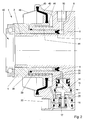
- the device 1 shown in Fig. 1 comprises a housing 2, which has coaxial with a longitudinal axis 3 has a recess 4, by the design of a shaft of a clutch (not shown) protrudes or in any case can protrude.
- annular piston 5 is slidably and sealingly mounted.
- the annular piston 5 has a first active surface 6, which is designed as an annular surface and is sealed or determined by a lip seal 7. It is understood that other sealing structures could be provided with which the active surface 6 is formed.
- the first active surface 6 closes off an actuating space 8, to which a hydraulic actuating line 9 is brought via a connection 10.
- a hydraulic transmission line not shown, is connected, which starts from a master cylinder, which is foot-operated, for example, to finally disengage the friction clutch when actuated.
- a control line 11 leads to a control chamber 12.
- the control chamber 12 is part of a multi-stepped bore 13 in the housing 2, which serves to accommodate a control piston 14 of a control valve 15.
- To the control valve 15 further includes a housing fixedly arranged and sealed insert body 16 in which a double valve body 17 is suspended suspended on a spring 18.
- the control piston 14 is stepped and has a hydraulic seal 19 which limits the control chamber 12. On the same diameter is a pneumatic Seal 20. On a comparatively larger diameter, a pneumatic seal 21 is provided. The seals 20 and 21 are housed in corresponding grooves 22 in the control piston 14. Furthermore, the control piston 14 has a hollow extension 23, which is configured to actuate the double valve body 17. The extension 23 has a protruding edge 24. The double valve body 17 carries a valve plate 25 made of elastic material. The edge 24 forms with the valve plate 25 an outlet valve 24, 25. The insert body 16 has a protruding edge 26, which forms an inlet valve 25, 26 together with the valve plate 25.
- the double valve body 17 has a seal 27 which, together with the inlet valve 25, 26 defines a reservoir 28 by the spring 18 is housed.
- the storage space 28 is connected via a line 29 and a port 30 and a not shown there connected line with a reservoir for compressed air (not shown) in constant communication. This compressed air is used as a servo force.
- an inflow chamber 31 Between the stepped control piston 14 and the insert body 16 is an inflow chamber 31, in which a return spring 32 is housed for the control piston 14.
- the inflow chamber 31 is constantly connected to a boosting space 34 via a pneumatic line 33.
- the common annular piston 5 has a second active surface 35 whose size is determined by two seals 36 and 37.
- the active surface 35 like the first active surface 6, is designed as an annular surface, but is preferably arranged on the outside, so that it is structurally easy to form a relatively large second active surface 35, which ultimately determines the reinforcement. It is understood that the second active surface 35 is pneumatically acted upon.
- the common annular piston 5 with the two active surfaces 6 and 35 has an axially extending recess 38 in which a preload spring 29 is housed, which is supported on the one hand on the annular piston 5 and on the other hand on the housing 2.
- the annular piston 5 acts directly on a designed as a ball bearing release bearing 40 of the friction clutch.
- the rotating elements of the friction clutch are separated from the non-rotating elements, in particular the annular piston 5.
- the housing 2 has an annular extension 41, which protrudes axially into a corresponding and relatively long annular groove 42 in the common annular piston 5. This design is aimed at providing a relatively large stroke, which is required once to bridge the required for the engagement and disengagement of the clutch game and on the other to bridge the resulting wear on the friction clutch.
- the annular extension 41 also forms running surfaces for the lip seal 7 and the seal 36.
- a hydraulic pressure in the operating space 8 is ultimately passed hydraulically via a foot-operated master cylinder.
- the annular piston 5 is in any case due to the action of the preload spring 39 to the release bearing 20 at.
- the control line 11 In the operating chamber 8 and thus acting on the first active surface 6 of the annular piston 5 results from the hydraulic pressure, a corresponding actuation force.
- hydraulically transmitted pressure via the control line 11 also enters the control chamber 12, so that the control piston 14 is displaced so that first the exhaust valve 24, 25 closes and opens the inlet valve 25, 26 in the sequence.
- the actuating force due to the hydraulic actuating pressure on the active surface 6 and the boosting force due to the pneumatic servo pressure on the second active surface 35 add up in the common annular piston, so that the release bearing 40 is acted upon in accordance with this total mechanical force.
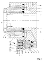
- FIG. 2 a second embodiment of the device 1 is shown. This embodiment is similar in many respects to the embodiment of FIG. 1, so that reference may be made thereto.
- the common annular piston 5 also has here the two active surfaces 6 and 35.
- the one seal 36 which seals the reinforcing space 34, is arranged here on the inside of the annular extension 41.
- the common annular piston 5 is externally sealed by means of a membrane 43, which is clamped sealingly on the one hand in an edge 44 on the annular piston 5 and on the other hand on an edge 45 of the housing 2.
- a housing cover 46 serves for the protected movement of the diaphragm 43 upon initiation of the servo pressure in the amplification space 34.
- the control valve 15 is basically designed in accordance with the embodiment of FIG. It is only housed with its axis rotated by 90 ° in the housing 2.
- the function and operation of the device according to FIG. 2 is analogous to the function and operation of the device according to FIG. 1.
- the illustrated in Fig. 3 further embodiment of the device 1 has the peculiarity that the annular piston 5 is formed divided or the internally disposed annular piston 5 is assigned a separate annular piston 47.
- the ring piston 5 carries the first active surface 6.
- the separate annular piston 47 carries the second active surface 35.
- the preload spring 39 acts on the separate annular piston 47.
- a separate preload spring 48 is provided for the annular piston 5, a separate preload spring 48 is provided.
- the control piston 14 of the control valve 15 is designed here somewhat differently.
- the Grooves 22 are used to selectively insert the seal 21 to change the gear ratio in adaptation to the specific conditions of a vehicle. The same applies to the hydraulic side.
- There are two optional usable grooves for the seal 19 here.
- the hollow extension 23 ends here between the seals 19 and 21, ie directly between the pneumatic and the hydraulic side.
- Fig. 4 illustrates a construction in which a common annular piston 5 is provided.
- the first active surface 6 is provided at a greater radius to the longitudinal axis 3 than the second active surface 35. This makes it clear that the arrangement of the two active surfaces 6 and 35 can also be realized in reverse.
- the control valve 15 is formed and arranged as already shown in FIG. 2.
- FIG. 5 is largely consistent with the embodiment of FIG.
- the double valve body 17 is formed here only as a continuous valve plate.
- the venting of the gain chamber 34 takes place here with an open outlet valve 24, 25 via a housing side provided vent opening 49 through the hollow extension 23 therethrough and thus between the seals 20 and 21st
- the embodiment of the device 1 shown in FIG. 6 is based on a two-part piston construction with an annular piston 5 and a separate annular piston 47.
- the separate annular piston 47 carries the second active surface 35 following the amplification space 34.
- a solenoid valve 50 is provided Parallel to the control valve 15, a solenoid valve 50 is provided. From the line 29 leading to the storage space 28, a line 51 branches off, which ends in front of the inlet seat of the solenoid valve 50.
- the solenoid valve 50 has its own vent 52. From the solenoid valve 50, a line 53 leads to a shuttle valve 54 and a line 55 to a blocking chamber 56.
- the blocking chamber 56 is provided with a brake lip 57, with which the annular piston 5 is then held when via the solenoid valve 50th arbitrarily the friction clutch should be disengaged.
- the shuttle valve 54 with its cantilevered valve body allows either the control of the boosting chamber 34 as a result of hydraulic actuation by introducing hydraulic pressure at the terminal 10 or arbitrarily as a result of an electrical signal to the solenoid valve 50. In this electrical actuation while missing from the hydraulic pressure on the Piston 5 provided force. Via the line 55, the blocking chamber 56 of the annular piston 5 is held, so that only the full supply pressure acts on the separate annular piston 5, which is thus used to disengage the friction clutch.
Abstract
Description
- Die Erfindung betrifft eine Vorrichtung zum wahlweisen Aus- bzw. Einrücken einer Reibkupplung für Kraftfahrzeuge, mit einem für den Durchtritt einer Welle durchbrochenen Gehäuse, in dem ein hydraulisch beaufschlagbarer Ringkolben mit einer ersten Wirkfläche gleitend und dichtend gelagert ist, der ein Ausrücklager der Reibkupplung betätigt.
- Eine Vorrichtung der eingangs beschriebenen Art ist aus der DE 102 22 730 A1 bekannt. Die Vorrichtung dient zum wahlweisen Aus- bzw. Einrücken einer Reibkupplung für Kraftfahrzeuge, wobei das Ausrücken der aktiven Betätigung zugeordnet ist. Das Betätigungsorgan wird manchmal auch als Zentralausrücker bezeichnet. Die Vorrichtung weist ein ortsfest anzuordnendes Gehäuse auf, in welchem ein Ringkolben verschiebbar und dichtend geführt ist, der hydraulisch beaufschlagbar ist. Die hydraulische Beaufschlagung wird beispielsweise durch einen Geberzylinder erzeugt, der mit dem Fuß betätigt wird. Die Bauart des Ringkolbens ist durch die Anwendung bedingt. Die Kupplung besitzt an dieser Stelle eine Welle, die die Vorrichtung durchsetzt und damit auch durch den Ringkolben hindurchreicht. Über den Ringkolben wird ein Ausrücklager der Reibkupplung betätigt. Dieses Ausrücklager ist nach Art eines Kugellagers ausgebildet, um die drehenden Elemente der Kupplung von den nicht drehenden Elementen der Vorrichtung und des Ringkolbens zu trennen. Zwischen dem Ringkolben und dem Ausrücklager sind mehrere Übertragungselemente vorgesehen. Die Vorrichtung weist auch eine Vorlastfeder auf, die die Aufgabe hat, die Anlage des Ringkolbens relativ zu dem Ausrücklager auch dann sicherzustellen, wenn keine hydraulische Beaufschlagung erfolgt.
- Da der Ringkolben der bekannten Vorrichtung hydraulisch über den fußkraftbetätigten Geberzylinder beaufschlagt wird, sind die dabei aufbringbaren Kräfte und erzeugbaren Drücke in dem hydraulischen Übertragungsmedium begrenzt. Es sind relativ hohe Betätigungskräfte erforderlich, um die Kupplung auszurücken. In dem hydraulischen Betätigungsmedium werden Drücke in der Größenordnung von 50-60 bar erzeugt. Die Dichtungen der Vorrichtung werden notwendigerweise immer mit diesen hohen Drücken beaufschlagt, so dass die Lebensdauer der Vorrichtung begrenzt ist. Bei einem Defekt an den Dichtungen besteht die Gefahr des Lufteintritts in das System, mit allen denkbaren nachteiligen Folgen bei einer hydraulischen Betätigung.
- Andererseits ist aus der DE 43 39 449 A1 ein Verstärker für hydraulische Steuerleitungen an Kraftfahrzeugen bekannt, der insbesondere in Verbindung mit einer Bremse oder auch einer Kupplung eingesetzt wird. Der Verstärker weist ein Gehäuse auf, welches einen Anschluss für eine hydraulische Steuerleitung besitzt, die an einen fußbetätigten Geberzylinder angeschlossen ist. In dem Gehäuse des Verstärkers ist ein Arbeitskolben gleitend und dichtend gelagert, dem ein kreisringförmiger Verstärkerkolben zugeordnet ist, der über eine pneumatische Druckluftquelle mit Hilfs- oder Servodruck zusätzlich beaufschlagt werden kann. Für die Steuerung des Hilfs- oder Servodrucks ist ein Steuerventil im Gehäuse des Verstärkers untergebracht. Das Steuerventil besitzt einen federnd aufgehängten Doppelventilkörper, der mit einem Steuerkolben zusammenarbeitet, der ebenfalls mit der hydraulischen Steuerleitung in Verbindung steht und über diese angesteuert werden kann. Damit wird der hydraulisch übertragenen Fußkraft eine Hilfs- oder Servokraft hinzugefügt. Beide Kräfte wirken über einen Arbeitskolben auf ein hydraulisches Medium, welches dann wiederum einem Nehmerzylinder zugeordnet bzw. an einen solchen angeschlossen ist.
- Der Erfindung liegt die Aufgabe zugrunde, eine Vorrichtung der eingangs beschriebenen Art zu schaffen, die bei einfachem Aufbau nur eine vergleichsweise niedrige Betätigungskraft erfordert.
- Die Aufgabe der Erfindung wird erfindungsgemäß mit den Merkmalen des unabhängigen Patentanspruchs 1 gelöst.
- Zwar ist es denkbar, den aus der DE-OS 43 39 449 A1 bekannten Verstärker der aus der DE 102 22 730 A1 bekannten Vorrichtung vorzuordnen. Dabei entsteht jedoch ein relativ komplizierter Aufbau mit einer Mehrzahl von Verbindungsleitungen und entsprechenden Leitungsanschlüssen. Gleichwohl werden die hydraulischen Dichtungen des Verstärkerkolbens des Verstärkers und des hydraulischen Nehmerzylinders in der Vorrichtung relativ hoch belastet, so dass die eingangs beschriebenen Nachteile nicht beseitigt werden.
- Der Erfindung liegt der Gedanke zugrunde, die bekannte Vorrichtung und den ebenfalls bekannten Verstärker zu einer Einheit zu integrieren und dabei zusätzlich die einzelnen Elemente so auszubilden und anzupassen, dass sich nicht nur ein einfacher Aufbau unter Wegfall von Verbindungsleitungen ergibt, sondern auch eine vergleichsweise niedrige Betätigungskraft ausreicht, um eine Reibkupplung ordnungsgemäß und mit vergleichsweise großer Lebensdauer betätigen zu können. Dabei wird der in einer solchen Kupplung auftretende Verschleiß und auch der erforderliche Bewegungsweg berücksichtigt bzw. überbrückt. Bei der Integration der beiden Vorrichtungen entsteht eine neue Einheit, die eine vergleichsweise niedrigere Anzahl von Einzelelementen umfasst. So übernimmt der Ringkolben der Vorrichtung auch die Funktion des Verstärkerkolbens des Verstärkers. Weiter kommt ein hydraulischer Arbeitsraum des Verstärkers auf der Ausgangsseite sowie die hydraulische Übertragung der verstärkten Kraft in Fortfall, weil die sich addierenden Kräfte ausgangsseitig von dem Ringkolben direkt mechanisch auf das Ausrücklager übertragen werden. Damit entfallen auch solche Dichtungen, die im Stand der Technik relativ hoch belastet sind und die Ursache für eine niedrige Lebensdauer darstellen. Die verbleibenden Dichtungen sind vergleichsweise niedriger belastet, so dass die Lebensdauer erhöht ist. Auch die Betriebssicherheit ist damit verbessert. Die neue Vorrichtung gestattet auch eine Notbetätigung für den Fall, dass der pneumatische Hilfs- oder Servodruck nicht zur Verfügung steht bzw. ausfällt. In diesem Falle muss zwar eine erhöhte Fußkraft angewendet werden. Eine Betätigung, d. h. ein Ausrücken der Reibkupplung ist aber dennoch möglich.
- Die erste Wirkfläche an dem Ringkolben ist als Kreisringfläche ausgebildet und wird nur von dem hydraulisch von einem Geberzylinder übertragenen Druck entsprechend der ausgeübten Fußkraft beaufschlagt. Die Belastung der zugehörigen Dichtung ist reduziert, weil eine kleinere Fußkraft für die Betätigung ausreicht. Auch die zweite Wirkfläche ist als Kreisringfläche ausgebildet. Die zugehörigen Dichtungen werden nur von dem Servodruck der pneumatischen Verstärkung, nicht aber von einem Druck resultierend aus der Summe der hydraulischen und pneumatischen Kräfte belastet. Die beiden Wirkflächen können an einem gemeinsamen Ringkolben verwirklicht sein. Es ist aber auch möglich, zusätzlich zum Ringkolben mit der ersten Wirkfläche einen gesonderten Ringkolben vorzusehen, der dann die zweite Wirkfläche trägt. Auch bei dieser Unterteilung des Ringkolbens in zwei konstruktive Einheiten wirken beide Einheiten direkt mechanisch auf das Ausrücklager ein. Die Addition der Kräfte erfolgt damit im mechanischen Teil der Vorrichtung.
- Das Gehäuse weist zweckmäßig einen zylindrischen Ringfortsatz auf, der die beiden Wirkflächen an dem oder den Ringkolben voneinander trennt. Der Ringfortsatz stellt einen entsprechenden Hub zur Verfügung, der es erlaubt, die erforderlichen Betätigungswege und den auftretenden Verschleiß in der Reibkupplung zu überbrücken. Der Ringfortsatz bildet gleichzeitig zwei Laufflächen für Dichtungen oder ermöglicht die Unterbringung einer Dichtung, die den pneumatischen Verstärkungsteil von dem hydraulischen Betätigungsteil trennt.
- Der Ringkolben kann eine sich axial erstreckende Ausnehmung aufweisen, in der eine Vorlastfeder angeordnet ist. In der Regel genügt eine einzige Vorlastfeder. Es können aber auch mehrere Vorlastfedern vorgesehen sein.
- Die erste, hydraulisch beaufschlagbare Wirkfläche ist auf kleinerem Radius als die zweite, pneumatisch beaufschlagbare Wirkfläche angeordnet. Dies vereinfacht es, die zweite Wirkfläche konstruktiv groß zu gestalten. Grundsätzlich ist aber auch die umgekehrte Anordnung möglich.
- Das Steuerventil kann einen federnd aufgehängten Doppelventilkörper und einen gestuften Steuerkolben aufweisen. Der Doppelventilkörper kann hohl ausgebildet sein. In diesem Falle ergibt sich eine einfache Möglichkeit, der Entlüftung des Verstärkerraums an der zweiten Wirkfläche durch den Doppelventilkörper hindurch. Der Doppelventilkörper kann aber auch als geschlossene Ventilplatte ausgebildet sein. In diesem Falle wird der Verstärkungsraum durch den ohnehin hohlen Fortsatz des Steuerkolbens entlüftet. An dem gestuften Steuerkolben sind zweckmäßig zwei Dichtungen gegen pneumatischen Druck vorgesehen, um die pneumatische Seite gegenüber der hydraulischen Betätigung mit erhöhter Sicherheit abzusperren.
- Der Steuerkolben kann zur Änderung des Übersetzungsverhältnisses mehrere auf unterschiedlichen Durchmessern angeordnete Nuten für die wahlweise Anordnung von Dichtungen aufweisen. Damit ist eine einfache Anpassung an bauliche Gegebenheiten möglich.
- Der Steuerkolben kann zur Betätigung des Doppelventilkörpers einen hohlen Fortsatz aufweisen, der der Entlüftung dient.
- Der Ringkolben oder der gesonderte Ringkolben kann auch über eine randseitig im Gehäuse eingespannte Membran dichtend geführt sein. Diese Möglichkeit ist unabhängig davon, ob ein gemeinsamer Ringkolben vorgesehen ist oder ein Ringkolben und eine gesonderter zusätzlicher Ringkolben.
- Das Ausrücklager sollte unmittelbar auf dem Ringkolben abgestützt sein. Dies ergibt die Addition der Kräfte im mechanischen Teil. Außerdem resultiert hieraus eine kurze Baulänge. Natürlich schadet eine Zwischenschaltung von Beilagescheiben nicht. Eine hydraulische Übertragungsstrecke mit all ihren Nachteilen wird aber auf jeden Fall vermieden.
- Im Folgenden wird die Erfindung anhand in den Figuren dargestellter bevorzugter Ausführungsbeispiele weiter erläutert und beschrieben.
- Fig. 1
- zeigt einen Schnitt durch eine erste Ausführungsform der Vorrichtung,
- Fig. 2
- zeigt einen Schnitte durch eine zweite Ausführungsform der Vorrichtung,
- Fig. 3
- zeigt einen Schnitt durch eine dritte Ausführungsform der Vorrichtung,
- Fig. 4
- zeigt einen Schnitt durch eine vierte Ausführungsform der Vorrichtung,
- Fig. 5
- zeigt einen Schnitt durch eine fünfte Ausführungsform der Vorrichtung, und
- Fig. 6
- zeigt einen Schnitt durch eine sechste Ausführungsform der Vorrichtung.
- Die in Fig. 1 dargestellte Vorrichtung 1 weist ein Gehäuse 2 auf, welches koaxial zu einer Längsachse 3 eine Ausnehmung 4 besitzt, durch die bauartbedingt eine Welle einer Kupplung (nicht dargestellt) hindurchragt oder jedenfalls hindurchragen kann.
- In dem Gehäuse 2 ist ein Ringkolben 5 gleitend und dichtend gelagert. Der Ringkolben 5 weist eine erste Wirkfläche 6 auf, die als Kreisringfläche ausgebildet ist und von einer Lippendichtung 7 abgedichtet bzw. bestimmt wird. Es versteht sich, dass auch andere Dichtungskonstruktionen vorgesehen sein könnten, mit denen die Wirkfläche 6 gebildet wird. Die erste Wirkfläche 6 schließt einen Betätigungsraum 8 ab, zu dem eine hydraulische Betätigungsleitung 9 über einen Anschluss 10 herangeführt ist. Am Anschluss 10 ist eine nicht dargestellte hydraulische Übertragungsleitung angeschlossen, die von einem Geberzylinder ausgeht, der beispielsweise fußbetätigt ist, um letztlich bei Betätigung die Reibkupplung auszurücken.
- Von dem Betätigungsraum 8 führt eine Steuerleitung 11 zu einer Steuerkammer 12. Die Steuerkammer 12 ist Bestandteil einer mehrfach gestuften Bohrung 13 im Gehäuse 2, die zur Unterbringung eines Steuerkolbens 14 eines Steuerventils 15 dient. Zu dem Steuerventil 15 gehört weiterhin ein Gehäuse fest angeordneter und abgedichteter Einsatzkörper 16, in dem ein Doppelventilkörper 17 auf einer Feder 18 aufgehängt abgestützt ist.
- Der Steuerkolben 14 ist gestuft ausgebildet und weist eine hydraulische Dichtung 19 auf, die die Steuerkammer 12 begrenzt. Auf gleichem Durchmesser befindet sich eine pneumatische Dichtung 20. Auf vergleichsweise größerem Durchmesser ist eine pneumatische Dichtung 21 vorgesehen. Die Dichtungen 20 und 21 sind in entsprechenden Nuten 22 im Steuerkolben 14 untergebracht. Weiterhin weist der Steuerkolben 14 einen hohlen Fortsatz 23 auf, der zur Betätigung des Doppelventilkörpers 17 ausgestaltet ist. Der Fortsatz 23 weist einen vorstehenden Rand 24 auf. Der Doppelventilkörper 17 trägt eine Ventilplatte 25 aus elastischem Material. Der Rand 24 bildet mit der Ventilplatte 25 ein Auslassventil 24, 25. Der Einsatzkörper 16 weist einen vorspringen Rand 26 auf, der zusammen mit der Ventilplatte 25 ein Einlassventil 25, 26 bildet. Weiter besitzt der Doppelventilkörper 17 eine Dichtung 27, die zusammen mit dem Einlassventil 25, 26 einen Vorratsraum 28 begrenzt, indem die Feder 18 untergebracht ist. Der Vorratsraum 28 steht über eine Leitung 29 und einen Anschluss 30 sowie eine nicht dargestellt dort angeschlossene Leitung mit einem Vorratsbehälter für Druckluft (nicht dargestellt) in ständiger Verbindung. Diese Druckluft wird als Servokraft genutzt.
- Zwischen dem gestuften Steuerkolben 14 und dem Einsatzkörper 16 befindet sich eine Einströmkammer 31, in der eine Rückführfeder 32 für den Steuerkolben 14 untergebracht ist. Die Einströmkammer 31 ist über eine pneumatische Leitung 33 ständig mit einem Verstärkungsraum 34 verbunden.
- Der gemeinsame Ringkolben 5 weist eine zweite Wirkfläche 35 auf, deren Größe durch zwei Dichtungen 36 und 37 bestimmt wird. Die Wirkfläche 35 ist ebenso wie die erste Wirkfläche 6 als Kreisringfläche ausgebildet, jedoch vorzugsweise außen angeordnet, so dass sich konstruktiv einfach eine relativ große zweite Wirkfläche 35 ausbilden lässt, die letztlich die Verstärkung bestimmt. Es versteht sich, dass die zweite Wirkfläche 35 pneumatisch beaufschlagt wird.
- Der gemeinsame Ringkolben 5 mit den beiden Wirkflächen 6 und 35 weist eine sich axial erstreckende Ausnehmung 38 auf, in der eine Vorlastfeder 29 untergebracht ist, die sich einerseits am Ringkolben 5 und andererseits am Gehäuse 2 abstützt. Es ist erkennbar, dass der Ringkolben 5 unmittelbar auf ein als Kugellager ausgebildetes Ausrücklager 40 der Reibkupplung einwirkt. Auf diese Weise werden die sich drehenden Elemente der Reibkupplung von den sich nicht drehenden Elementen, insbesondere dem Ringkolben 5 getrennt. Durch diese konstruktive Ausbildung und Anordnung des Ringkolbens 5 relativ zum Ausrücklager 40 addieren sich die über die erste Wirkfläche 6 hydraulisch aufgebrachte Kraft und die über die Wirkfläche 35 im Betätigungsfall aufgebrachte pneumatische Zusatzkraft im mechanischen Teil. Damit wird vorteilhaft auf die Weiterleitung eines hydraulischen Druckes, der der Addition der Kräfte entspricht, verzichtet.
- Das Gehäuse 2 weißt einen Ringfortsatz 41 auf, der axial in eine entsprechende und relativ lang gestaltete Ringnut 42 im gemeinsamen Ringkolben 5 einragt. Diese Gestaltung zielt auf die Bereitstellung eines relativ großen Hubes ab, der erforderlich ist, um einmal das zum Ein- und Ausrücken der Kupplung erforderliche Spiel und zum anderen den an der Reibkupplung entstehenden Verschleiß zu überbrücken. Der Ringfortsatz 41 bildet weiterhin Laufflächen für die Lippendichtung 7 und die Dichtung 36.
- Zur Betätigung der Reibkupplung, also zum Ausrücken, wird auf hydraulischem Wege über einen fußbetätigten Geberzylinder letztlich ein hydraulischer Druck in den Betätigungsraum 8 geleitet. Der Ringkolben 5 liegt in Folge der Einwirkung der Vorlastfeder 39 ohnehin an dem Ausrücklager 20 an. Im Betätigungsraum 8 und damit auf die erste Wirkfläche 6 des Ringkolbens 5 einwirkend ergibt sich aus dem hydraulischen Druck eine entsprechende Betätigungskraft. Gleichzeitig gelangt hydraulisch übertragener Druck über die Steuerleitung 11 auch in die Steuerkammer 12, so dass der Steuerkolben 14 so verschoben wird, dass zunächst das Auslassventil 24, 25 schließt und in der Folge das Einlassventil 25, 26 öffnet. Der im Vorratsraum 28 anstehende pneumatische Hilfsdruck gelangt damit über das geöffnete Einlassventil 25, 26 in die Einströmkammer 31 und von dort über die Leitung 33 in den Verstärkungsraum 34, so dass damit die zweite Wirkfläche 35 beaufschlagt wird. In der Folge wird die Kupplung ausgerückt und der dazu erforderliche Hub zurückgelegt. Durch die Durchmesserdifferenz zwischen den Dichtungen 21 und 19 am Steuerkolben 14 ist ein Übersetzungsverhältnis zwischen dem hydraulischen Betätigungsdruck und dem pneumatischen Servodruck festgelegt. Entsprechend erfolgt eine Auswiegung am Steuerkolben 14, in den auch die Vorspannkraft der Rückführfeder 32 eingeht. Es stellt sich dann eine Abschlussstellung am Steuerventil 15 ein, bei dem sowohl das Einlassventil 25, 26 wie auch das Auslassventil 24, 25 geschlossen sind.
- Die Betätigungskraft in Folge des hydraulischen Betätigungsdruckes auf der Wirkfläche 6 und die Verstärkungskraft aufgrund des pneumatischen Servodruckes auf der zweiten Wirkfläche 35 addieren sich im gemeinsamen Ringkolben, so dass mit dieser mechanisch agierten Gesamtkraft das Ausrücklager 40 entsprechend beaufschlagt wird.
- Zur Beendigung des Auskuppelvorgangs und damit zum Einrücken der Reibkupplung wird die hydraulische Betätigungskraft weggenommen, so dass die erste Wirkfläche 6 entsprechend entlastet wird. Gleichzeitig damit wird auch der Steuerkolben 14 in der Steuerkammer 12 entlastet, so dass die in der Einströmkammer 31 wirksame Druckkraft den Steuerkolben 14 in seine Ausgangslage zurückschiebt. Damit entfernt sich auch der hohle Fortsatz 23 von der Ventilplatte 25 und das Auslassventil 24, 25 wird geöffnet. Durch den hohlen Doppelventilkörper 17 wird damit der Verstärkungsraum 34 an die Atmosphäre angeschlossen, also entlüftet. Gleichzeitig erfolgt durch den hohlen Fortsatz 23 und eine zwischen den Dichtungen 20 und 21 endende Verbindungsleitung auch eine Entlüftung dieses eingeschlossenen Raumes zwischen den Dichtungen 20 und 21.
- In Fig. 2 ist eine zweite Ausführungsform der Vorrichtung 1 dargestellt. Diese Ausführungsform ist in weiten Bereichen ähnlich ausgebildet wie die Ausführungsform der Fig. 1, so dass hierauf verwiesen werden kann. Der gemeinsame Ringkolben 5 besitzt auch hier die beiden Wirkflächen 6 und 35. Die eine Dichtung 36, die den Verstärkungsraum 34 abdichtet, ist hier innen an dem Ringfortsatz 41 angeordnet.
- Der gemeinsame Ringkolben 5 ist außen mit Hilfe einer Membran 43 abgedichtet, die einerseits in einem Rand 44 am Ringkolben 5 und andererseits an einem Rand 45 des Gehäuses 2 dichtend eingespannt ist. Ein Gehäusedeckel 46 dient der geschützten Bewegung der Membran 43 bei Einleitung des Servodruckes in den Verstärkungsraum 34.
- Das Steuerventil 15 ist hier grundsätzlich übereinstimmend zu der Ausführungsform der Fig. 1 ausgebildet. Es ist lediglich mit seiner Achse um 90° gedreht im Gehäuse 2 untergebracht.
- Die Funktion und Arbeitsweise der Vorrichtung gemäß Fig. 2 verläuft analog der Funktion und Arbeitsweise der Vorrichtung gemäß Fig. 1.
- Die in Fig. 3 dargestellte weitere Ausführungsform der Vorrichtung 1 weist die Besonderheit auf, dass der Ringkolben 5 geteilt ausgebildet ist bzw. dem innen angeordneten Ringkolben 5 ein gesonderter Ringkolben 47 zugeordnet ist. Der Ringkolben 5 trägt die erste Wirkfläche 6. Der gesonderte Ringkolben 47 trägt die zweite Wirkfläche 35. Die Vorlastfeder 39 wirkt auf den gesonderten Ringkolben 47. Für den Ringkolben 5 ist eine gesonderte Vorlastfeder 48 vorgesehen. Der Steuerkolben 14 des Steuerventils 15 ist hier etwas anders gestaltet. Die Nuten 22 dienen dem wahlweisen Einsetzen der Dichtung 21 zur Veränderung des Übersetzungsverhältnisses in Anpassung an die speziellen Gegebenheiten eines Fahrzeuges. Gleiches gilt auch für die hydraulische Seite. Es sind hier zwei wahlweise nutzbare Nuten für die Dichtung 19 vorgesehen. Der hohle Fortsatz 23 endet hier zwischen den Dichtungen 19 und 21, also unmittelbar zwischen der pneumatischen und der hydraulischen Seite.
- Fig. 4 verdeutlicht eine Konstruktion, bei der ein gemeinsamer Ringkolben 5 vorgesehen ist. Im Unterschied zur Ausführungsform der Fig. 1 ist hier die erste Wirkfläche 6 auf größerem Radius zu der Längsachse 3 vorgesehen als die zweite Wirkfläche 35. Damit wird verdeutlicht, dass die Anordnung der beiden Wirkflächen 6 und 35 auch umgekehrt verwirklicht sein kann. Das Steuerventil 15 ist so ausgebildet und angeordnet, wie dies bereits Fig. 2 zeigt.
- Die Ausführungsform der Fig. 5 stimmt in weiten Teilen mit der Ausführungsform gemäß Fig. 4 überein. Der Doppelventilkörper 17 ist hier lediglich als durchgehende Ventilplatte ausgebildet. Die Entlüftung des Verstärkungsraumes 34 erfolgt hier bei geöffnetem Auslassventil 24, 25 über eine gehäuseseitig vorgesehene Entlüftungsöffnung 49 durch den hohlen Fortsatz 23 hindurch und damit zwischen den Dichtungen 20 und 21.
- Es versteht sich, dass bei allen Ausführungsformen eine Notbetätigung möglich ist, wenn die pneumatische Hilfskraft ausgefallen ist. In diesem Falle kann das Ausrücken der Reibkupplung nur auf hydraulischem Wege erfolgen, d.h. der Ausrückvorgang erfordert eine erhöhte Fußkraft, die allein über die erste Wirkfläche 6 einwirkt.
- Die in Fig. 6 dargestellte Ausführungsform der Vorrichtung 1 baut auf einer zweiteiligen Kolbenkonstruktion mit einem Ringkolben 5 und einem gesonderten Ringkolben 47 auf. Der gesonderte Ringkolben 47 trägt die zweite Wirkfläche 35 im Anschluss an den Verstärkungsraum 34. Parallel zu dem Steuerventil 15 ist ein Magnetventil 50 vorgesehen. Von der Leitung 29, die zum Vorratsraum 28 führt, zweigt eine Leitung 51 ab, die vor dem Einlasssitz des Magnetventils 50 endet. Das Magnetventil 50 weist eine eigene Entlüftungsöffnung 52 auf. Vom Magnetventil 50 führt eine Leitung 53 zu einem Wechselventil 54 und eine Leitung 55 zu einer Blockierkammer 56. Die Blockierkammer 56 ist mit einer Bremslippe 57 versehen, mit der der Ringkolben 5 dann festgehalten wird, wenn über das Magnetventil 50 willkürlich die Reibkupplung ausgekuppelt werden soll. Das Wechselventil 54 mit seinem fliegend gelagerten Ventilkörper gestattet entweder die Ansteuerung des Verstärkungsraums 34 in Folge hydraulischer Betätigung durch Einleitung hydraulischen Druckes am Anschluss 10 oder willkürlich in Folge eines elektrischen Signals auf das Magnetventil 50. Bei dieser elektrischen Betätigung fehlt zwar die vom hydraulischen Druck auf den Kolben 5 bereitgestellte Kraft. Über die Leitung 55 wird die Blockierkammer 56 der Ringkolben 5 festgehalten, so dass auf den gesonderten Ringkolben 5 somit nur noch der volle Vorratsdruck einwirkt, der so zum Ausrücken der Reibkupplung genutzt wird.
-
- 1
- Vorrichtung
- 2
- Gehäuse
- 3
- Längsachse
- 4
- Ausnehmung
- 5
- Ringkolben
- 6
- Wirkfläche
- 7
- Lippendichtung
- 8
- Betätigungsraum
- 9
- Betätigungsleitung
- 10
- Anschluss
- 11
- Steuerleitung
- 12
- Steuerkammer
- 13
- Bohrung
- 14
- Steuerkolben
- 15
- Steuerventil
- 16
- Einsatzkörper
- 17
- Doppelventilkörper
- 18
- Feder
- 19
- Dichtung
- 20
- Dichtung
- 21
- Dichtung
- 22
- Nut
- 23
- Fortsatz
- 24
- Rand
- 25
- Ventilplatte
- 26
- Rand
- 27
- Dichtung
- 28
- Vorratsraum
- 29
- Leitung
- 30
- Anschluss
- 31
- Einströmkammer
- 32
- Rückführfeder
- 33
- Leitung
- 34
- Verstärkungsraum
- 35
- Wirkfläche
- 36
- Dichtung
- 37
- Dichtung
- 38
- Ausnehmung
- 39
- Vorlastfeder
- 40
- Ausrücklager
- 41
- Ringfortsatz
- 42
- Ringnut
- 43
- Membran
- 44
- Rand
- 45
- Rand
- 46
- Gehäusedeckel
- 47
- Ringkolben
- 48
- Vorlastfeder
- 49
- Entlüftungsöffnung
- 50
- Magnetventil
- 51
- Leitung
- 52
- Entlüftungsöffnung
- 53
- Leitung
- 54
- Wechselventil
- 55
- Leitung
- 56
- Blockierkammer
- 57
- Bremslippe
Claims (10)
- Vorrichtung zum wahlweisen Aus- bzw. Einrücken einer Reibkupplung für Kraftfahrzeuge, mit einem für den Durchtritt einer Welle durchbrochenen Gehäuse (2), in dem ein hydraulisch beaufschlagbarer Ringkolben (5) mit einer ersten Wirkfläche (6) gleitend und dichtend gelagert ist, der ein Ausrücklager (40) der Reibkupplung betätigt, dadurch gekennzeichnet, dass am Ringkolben (5) oder an einem gesonderten Ringkolben (47) eine zweite Wirkfläche (35) vorgesehen ist, die mit einem pneumatischen Hilfs- oder Servodruck beaufschlagbar ist, und dass im Gehäuse (2) der Vorrichtung (1) ein Steuerventil (15) für die Beaufschlagung der zweiten Wirkfläche (35) mit dem Hilfs- oder Servodruck angeordnet ist, welches über eine Steuerleitung (11) mit der ersten Wirkfläche (6) des hydraulisch beaufschlagten Ringkolbens (5) verbunden ist.
- Vorrichtung nach Anspruch 1, dadurch gekennzeichnet, dass auch die zweite Wirkfläche (35) als Kreisringfläche ausgebildet ist.
- Vorrichtung nach Anspruch 1 und 2, dadurch gekennzeichnet, dass das Gehäuse (2) einen zylindrischen Ringfortsatz (41) aufweist, der die beiden Wirkflächen (6, 35) an dem oder den Ringkolben (5; 47) voneinander trennt.
- Vorrichtung nach mindestens einem der Ansprüche 1 bis 3, dadurch gekennzeichnet, dass der Ringkolben (5) eine sich axial erstreckende Ausnehmung (38) aufweist, in der eine Vorlastfeder (39) angeordnet ist.
- Vorrichtung nach mindestens einem der Ansprüche 1 bis 4, dadurch gekennzeichnet, dass die erste, hydraulisch beaufschlagbare Wirkfläche (6) auf kleinerem Radius als die zweite, pneumatisch beaufschlagbare Wirkfläche (35) angeordnet ist.
- Vorrichtung nach mindestens einem der Ansprüche 1 bis 5, dadurch gekennzeichnet, dass das Steuerventil (15) einen federnd aufgehängten Doppelventilkörper (17) und einen gestuften Steuerkolben (14) aufweist.
- Vorrichtung nach mindestens einem der Ansprüche 1 bis 6, dadurch gekennzeichnet, dass der Steuerkolben (14) zur Änderung des Übersetzungsverhältnisses mehrere auf unterschiedlichen Durchmessern angeordnete Nuten (22) für die wahlweise Anordnung von Dichtungen (19; 21) aufweist.
- Vorrichtung nach mindestens einem der Ansprüche 1 bis 7, dadurch gekennzeichnet, dass der Steuerkolben (14) zur Betätigung des Doppelventilkörpers (17) einen hohlen Fortsatz (23) aufweist.
- Vorrichtung nach mindestens einem der Ansprüche 1 bis 8, dadurch gekennzeichnet, dass der Ringkolben (5) oder der gesonderte Ringkolben (47) über eine randseitig im Gehäuse (2) eingespannte Membran (43) dichtend geführt ist.
- Vorrichtung nach mindestens einem der Ansprüche 1 bis 9, dadurch gekennzeichnet, dass das Ausrücklager (40) unmittelbar auf dem Ringkolben (5; 47) abgestützt ist.
Applications Claiming Priority (1)
| Application Number | Priority Date | Filing Date | Title |
|---|---|---|---|
| DE102004041776A DE102004041776B4 (de) | 2004-08-28 | 2004-08-28 | Vorrichtung zum wahlweisen Aus- bzw. Einrücken einer Reibkupplung für Kraftfahrzeuge |
Publications (2)
| Publication Number | Publication Date |
|---|---|
| EP1630439A1 true EP1630439A1 (de) | 2006-03-01 |
| EP1630439B1 EP1630439B1 (de) | 2007-10-03 |
Family
ID=35295759
Family Applications (1)
| Application Number | Title | Priority Date | Filing Date |
|---|---|---|---|
| EP05018227A Not-in-force EP1630439B1 (de) | 2004-08-28 | 2005-08-23 | Vorrichtung zum wahlweisen Aus- bzw. Einrücken einer Reibkupplung für Kraftfahrzeuge |
Country Status (3)
| Country | Link |
|---|---|
| EP (1) | EP1630439B1 (de) |
| AT (1) | ATE374893T1 (de) |
| DE (2) | DE102004041776B4 (de) |
Cited By (4)
| Publication number | Priority date | Publication date | Assignee | Title |
|---|---|---|---|---|
| EP2048399A1 (de) * | 2007-10-11 | 2009-04-15 | LuK Lamellen und Kupplungsbau Beteiligungs KG | Kupplungsnehmerzylinder |
| EP2053260A2 (de) * | 2007-10-25 | 2009-04-29 | KNORR-BREMSE Systeme für Nutzfahrzeuge GmbH | Kupplungskraftverstärker |
| EP2053261A2 (de) * | 2007-10-25 | 2009-04-29 | KNORR-BREMSE Systeme für Nutzfahrzeuge GmbH | Kupplungskraftverstärker |
| WO2017129217A1 (de) * | 2016-01-26 | 2017-08-03 | Fte Automotive Gmbh | Aktuator, insbesondere nehmerzylinder, für eine vorrichtung zur kupplungsbetätigung in einem kraftfahrzeug |
Families Citing this family (4)
| Publication number | Priority date | Publication date | Assignee | Title |
|---|---|---|---|---|
| DE102014102880B4 (de) * | 2014-03-05 | 2015-10-08 | Knorr-Bremse Systeme für Nutzfahrzeuge GmbH | Kupplungskraftverstärker mit im Bereich der Kolbenstange angeordneten speziellen dynamischen Dichtungsmitteln |
| DE102016000707A1 (de) | 2016-01-26 | 2017-07-27 | Fte Automotive Gmbh | Vorrichtung zur Betätigung einer Kupplung |
| DE102019105968B4 (de) * | 2019-03-08 | 2020-10-15 | Knorr-Bremse Systeme für Nutzfahrzeuge GmbH | Druckmittelbetriebener Kupplungsaktuator |
| DE102022209485A1 (de) | 2022-09-12 | 2024-03-14 | Zf Friedrichshafen Ag | Zentralausrücker |
Citations (3)
| Publication number | Priority date | Publication date | Assignee | Title |
|---|---|---|---|---|
| FR2604228A1 (fr) * | 1986-09-19 | 1988-03-25 | Renault Vehicules Ind | Dispositif d'embrayage avec crabotage. |
| DE3842722C1 (en) * | 1988-12-19 | 1990-06-13 | Bayerische Motoren Werke Ag, 8000 Muenchen, De | Actuating device for a friction clutch arranged in the drive train of a motor vehicle |
| US5806648A (en) * | 1995-09-19 | 1998-09-15 | Valeo | Fluid pressure ram provided with a sliding intermediate chamber |
Family Cites Families (7)
| Publication number | Priority date | Publication date | Assignee | Title |
|---|---|---|---|---|
| DE3709166C1 (de) * | 1987-03-20 | 1988-09-22 | Knorr Bremse Ag | Hydropneumatischer Kupplungsverstaerker fuer Kraftfahrzeuge |
| DE4339449C2 (de) * | 1993-11-19 | 1998-03-26 | Grau Gmbh | Verstärker für hydraulische Steuerleitungen an Kraftfahrzeugen |
| FR2738884B1 (fr) * | 1995-09-19 | 1997-10-24 | Valeo | Verin a deux chambres de commande et butee de debrayage munie d'un tel verin |
| ES2150832B1 (es) * | 1996-06-12 | 2001-06-16 | Fichtel & Sachs Ag | Dispositivo de maniobra para la maniobra, en particular maniobra neumatica, de un embrague de friccion. |
| DE19714226A1 (de) * | 1997-04-07 | 1998-10-08 | Mannesmann Sachs Ag | Betätigungseinrichtung für die Betätigung, insbesondere pneumatische Betätigung einer Reibungskupplung |
| DE19945806A1 (de) * | 1998-11-19 | 2000-05-25 | Mannesmann Sachs Ag | Betätigungseinrichtung |
| DE10222730A1 (de) * | 2002-05-23 | 2003-12-11 | Fte Automotive Gmbh | Vorrichtung zum wahlweise Aus-bzw. Einrücken einer Reibkupplung für Kraftfahrzeuge |
-
2004
- 2004-08-28 DE DE102004041776A patent/DE102004041776B4/de not_active Expired - Fee Related
-
2005
- 2005-08-23 DE DE502005001602T patent/DE502005001602D1/de active Active
- 2005-08-23 EP EP05018227A patent/EP1630439B1/de not_active Not-in-force
- 2005-08-23 AT AT05018227T patent/ATE374893T1/de not_active IP Right Cessation
Patent Citations (3)
| Publication number | Priority date | Publication date | Assignee | Title |
|---|---|---|---|---|
| FR2604228A1 (fr) * | 1986-09-19 | 1988-03-25 | Renault Vehicules Ind | Dispositif d'embrayage avec crabotage. |
| DE3842722C1 (en) * | 1988-12-19 | 1990-06-13 | Bayerische Motoren Werke Ag, 8000 Muenchen, De | Actuating device for a friction clutch arranged in the drive train of a motor vehicle |
| US5806648A (en) * | 1995-09-19 | 1998-09-15 | Valeo | Fluid pressure ram provided with a sliding intermediate chamber |
Cited By (7)
| Publication number | Priority date | Publication date | Assignee | Title |
|---|---|---|---|---|
| EP2048399A1 (de) * | 2007-10-11 | 2009-04-15 | LuK Lamellen und Kupplungsbau Beteiligungs KG | Kupplungsnehmerzylinder |
| EP2053260A2 (de) * | 2007-10-25 | 2009-04-29 | KNORR-BREMSE Systeme für Nutzfahrzeuge GmbH | Kupplungskraftverstärker |
| EP2053261A2 (de) * | 2007-10-25 | 2009-04-29 | KNORR-BREMSE Systeme für Nutzfahrzeuge GmbH | Kupplungskraftverstärker |
| EP2053260A3 (de) * | 2007-10-25 | 2010-10-06 | KNORR-BREMSE Systeme für Nutzfahrzeuge GmbH | Kupplungskraftverstärker |
| EP2053261A3 (de) * | 2007-10-25 | 2010-10-06 | KNORR-BREMSE Systeme für Nutzfahrzeuge GmbH | Kupplungskraftverstärker |
| WO2017129217A1 (de) * | 2016-01-26 | 2017-08-03 | Fte Automotive Gmbh | Aktuator, insbesondere nehmerzylinder, für eine vorrichtung zur kupplungsbetätigung in einem kraftfahrzeug |
| US10774882B2 (en) | 2016-01-26 | 2020-09-15 | Fte Automotive Gmbh | Actuator, in particular slave cylinder, for a device for a clutch actuation in a motor vehicle |
Also Published As
| Publication number | Publication date |
|---|---|
| ATE374893T1 (de) | 2007-10-15 |
| DE102004041776A1 (de) | 2006-03-09 |
| DE502005001602D1 (de) | 2007-11-15 |
| EP1630439B1 (de) | 2007-10-03 |
| DE102004041776B4 (de) | 2009-01-29 |
Similar Documents
| Publication | Publication Date | Title |
|---|---|---|
| EP1630439B1 (de) | Vorrichtung zum wahlweisen Aus- bzw. Einrücken einer Reibkupplung für Kraftfahrzeuge | |
| DE102007053765B4 (de) | Manuell betätigbares Ventil für eine Bremsanlage eines Anhängers | |
| DE102010037349B4 (de) | Parkventil für einen Nutzfahrzeug-Anhänger | |
| EP2359040B1 (de) | Ventil und montageverfahren | |
| EP1794045B1 (de) | Bremszylinder für fahrzeugbremsen | |
| EP2812218B1 (de) | Verfahren zum betrieb eines kombinierten betriebs- und feststellbremszylinders | |
| EP2238004A2 (de) | Parkbremse | |
| EP2812219B1 (de) | Kombinierter betriebs- und feststellbremszylinder mit durch den betriebsbremsdruck gesteuertem feststellbremskolben | |
| EP3228512B1 (de) | Park-löse-ventil für ein anhängefahrzeug | |
| DE102008044819A1 (de) | Hydraulisches Element | |
| DE202018001859U1 (de) | Bremssystem eines Zugfahrzeugs | |
| DE19918070B4 (de) | Druckregelvorrichtung für elektro-pneumatische Bremsanlagen von Fahrzeugen, insbesondere Nutzfahrzeugen | |
| DE102016217381A1 (de) | Fluidanordnung zum fluidischen Betätigen von Kraftfahrzeugkomponenten | |
| DE102016008215A1 (de) | Park-Löse-Ventil für ein Anhängefahrzeug | |
| EP3429898B1 (de) | Park-löse-ventil für ein anhängefahrzeug | |
| DE102009049246A1 (de) | Kupplungspedalkraftunterstützungseinrichtung | |
| EP1597126B1 (de) | Bremssystem | |
| DE102018002488B4 (de) | Bremssystem eines Fahrzeugzuges | |
| DE102006015850A1 (de) | Vorrichtung zur Bremsbestätigung eines Kraftfahrzeuges | |
| DE102005052692B3 (de) | Elektrohydraulische Überwachungseinrichtung | |
| DE102009021893A1 (de) | Dämpfungsfilter | |
| DE102009058404A1 (de) | Schaltungsanordnung zur Ansteuerung eines doppelt wirkenden Verbrauchers | |
| EP0422345B1 (de) | Umschaltventil für Fahrzeuge | |
| DE10325875A1 (de) | Bremssystem | |
| DE102009012952A1 (de) | Ventilbaugruppe |
Legal Events
| Date | Code | Title | Description |
|---|---|---|---|
| PUAI | Public reference made under article 153(3) epc to a published international application that has entered the european phase |
Free format text: ORIGINAL CODE: 0009012 |
|
| AK | Designated contracting states |
Kind code of ref document: A1 Designated state(s): AT BE BG CH CY CZ DE DK EE ES FI FR GB GR HU IE IS IT LI LT LU LV MC NL PL PT RO SE SI SK TR |
|
| AX | Request for extension of the european patent |
Extension state: AL BA HR MK YU |
|
| 17P | Request for examination filed |
Effective date: 20060318 |
|
| AKX | Designation fees paid |
Designated state(s): AT BE BG CH CY CZ DE DK EE ES FI FR GB GR HU IE IS IT LI LT LU LV MC NL PL PT RO SE SI SK TR |
|
| GRAP | Despatch of communication of intention to grant a patent |
Free format text: ORIGINAL CODE: EPIDOSNIGR1 |
|
| GRAS | Grant fee paid |
Free format text: ORIGINAL CODE: EPIDOSNIGR3 |
|
| GRAA | (expected) grant |
Free format text: ORIGINAL CODE: 0009210 |
|
| AK | Designated contracting states |
Kind code of ref document: B1 Designated state(s): AT BE BG CH CY CZ DE DK EE ES FI FR GB GR HU IE IS IT LI LT LU LV MC NL PL PT RO SE SI SK TR |
|
| REG | Reference to a national code |
Ref country code: GB Ref legal event code: FG4D Free format text: NOT ENGLISH |
|
| GBT | Gb: translation of ep patent filed (gb section 77(6)(a)/1977) |
Effective date: 20071003 |
|
| REG | Reference to a national code |
Ref country code: CH Ref legal event code: EP |
|
| REG | Reference to a national code |
Ref country code: IE Ref legal event code: FG4D Free format text: LANGUAGE OF EP DOCUMENT: GERMAN |
|
| REF | Corresponds to: |
Ref document number: 502005001602 Country of ref document: DE Date of ref document: 20071115 Kind code of ref document: P |
|
| NLV1 | Nl: lapsed or annulled due to failure to fulfill the requirements of art. 29p and 29m of the patents act | ||
| PG25 | Lapsed in a contracting state [announced via postgrant information from national office to epo] |
Ref country code: ES Free format text: LAPSE BECAUSE OF FAILURE TO SUBMIT A TRANSLATION OF THE DESCRIPTION OR TO PAY THE FEE WITHIN THE PRESCRIBED TIME-LIMIT Effective date: 20080114 Ref country code: NL Free format text: LAPSE BECAUSE OF FAILURE TO SUBMIT A TRANSLATION OF THE DESCRIPTION OR TO PAY THE FEE WITHIN THE PRESCRIBED TIME-LIMIT Effective date: 20071003 Ref country code: SE Free format text: LAPSE BECAUSE OF FAILURE TO SUBMIT A TRANSLATION OF THE DESCRIPTION OR TO PAY THE FEE WITHIN THE PRESCRIBED TIME-LIMIT Effective date: 20080103 |
|
| PG25 | Lapsed in a contracting state [announced via postgrant information from national office to epo] |
Ref country code: BG Free format text: LAPSE BECAUSE OF FAILURE TO SUBMIT A TRANSLATION OF THE DESCRIPTION OR TO PAY THE FEE WITHIN THE PRESCRIBED TIME-LIMIT Effective date: 20080103 Ref country code: IS Free format text: LAPSE BECAUSE OF FAILURE TO SUBMIT A TRANSLATION OF THE DESCRIPTION OR TO PAY THE FEE WITHIN THE PRESCRIBED TIME-LIMIT Effective date: 20080203 Ref country code: LT Free format text: LAPSE BECAUSE OF FAILURE TO SUBMIT A TRANSLATION OF THE DESCRIPTION OR TO PAY THE FEE WITHIN THE PRESCRIBED TIME-LIMIT Effective date: 20071003 Ref country code: PT Free format text: LAPSE BECAUSE OF FAILURE TO SUBMIT A TRANSLATION OF THE DESCRIPTION OR TO PAY THE FEE WITHIN THE PRESCRIBED TIME-LIMIT Effective date: 20080303 Ref country code: LV Free format text: LAPSE BECAUSE OF FAILURE TO SUBMIT A TRANSLATION OF THE DESCRIPTION OR TO PAY THE FEE WITHIN THE PRESCRIBED TIME-LIMIT Effective date: 20071003 Ref country code: PL Free format text: LAPSE BECAUSE OF FAILURE TO SUBMIT A TRANSLATION OF THE DESCRIPTION OR TO PAY THE FEE WITHIN THE PRESCRIBED TIME-LIMIT Effective date: 20071003 |
|
| REG | Reference to a national code |
Ref country code: IE Ref legal event code: FD4D |
|
| EN | Fr: translation not filed | ||
| PG25 | Lapsed in a contracting state [announced via postgrant information from national office to epo] |
Ref country code: DK Free format text: LAPSE BECAUSE OF FAILURE TO SUBMIT A TRANSLATION OF THE DESCRIPTION OR TO PAY THE FEE WITHIN THE PRESCRIBED TIME-LIMIT Effective date: 20071003 Ref country code: CZ Free format text: LAPSE BECAUSE OF FAILURE TO SUBMIT A TRANSLATION OF THE DESCRIPTION OR TO PAY THE FEE WITHIN THE PRESCRIBED TIME-LIMIT Effective date: 20071003 |
|
| PLBE | No opposition filed within time limit |
Free format text: ORIGINAL CODE: 0009261 |
|
| STAA | Information on the status of an ep patent application or granted ep patent |
Free format text: STATUS: NO OPPOSITION FILED WITHIN TIME LIMIT |
|
| PG25 | Lapsed in a contracting state [announced via postgrant information from national office to epo] |
Ref country code: RO Free format text: LAPSE BECAUSE OF FAILURE TO SUBMIT A TRANSLATION OF THE DESCRIPTION OR TO PAY THE FEE WITHIN THE PRESCRIBED TIME-LIMIT Effective date: 20071003 Ref country code: SK Free format text: LAPSE BECAUSE OF FAILURE TO SUBMIT A TRANSLATION OF THE DESCRIPTION OR TO PAY THE FEE WITHIN THE PRESCRIBED TIME-LIMIT Effective date: 20071003 |
|
| 26N | No opposition filed |
Effective date: 20080704 |
|
| PG25 | Lapsed in a contracting state [announced via postgrant information from national office to epo] |
Ref country code: FR Free format text: LAPSE BECAUSE OF FAILURE TO SUBMIT A TRANSLATION OF THE DESCRIPTION OR TO PAY THE FEE WITHIN THE PRESCRIBED TIME-LIMIT Effective date: 20080718 Ref country code: IE Free format text: LAPSE BECAUSE OF FAILURE TO SUBMIT A TRANSLATION OF THE DESCRIPTION OR TO PAY THE FEE WITHIN THE PRESCRIBED TIME-LIMIT Effective date: 20071003 |
|
| PG25 | Lapsed in a contracting state [announced via postgrant information from national office to epo] |
Ref country code: GR Free format text: LAPSE BECAUSE OF FAILURE TO SUBMIT A TRANSLATION OF THE DESCRIPTION OR TO PAY THE FEE WITHIN THE PRESCRIBED TIME-LIMIT Effective date: 20080104 |
|
| PG25 | Lapsed in a contracting state [announced via postgrant information from national office to epo] |
Ref country code: MC Free format text: LAPSE BECAUSE OF NON-PAYMENT OF DUE FEES Effective date: 20080831 |
|
| PG25 | Lapsed in a contracting state [announced via postgrant information from national office to epo] |
Ref country code: EE Free format text: LAPSE BECAUSE OF FAILURE TO SUBMIT A TRANSLATION OF THE DESCRIPTION OR TO PAY THE FEE WITHIN THE PRESCRIBED TIME-LIMIT Effective date: 20071003 |
|
| PG25 | Lapsed in a contracting state [announced via postgrant information from national office to epo] |
Ref country code: SI Free format text: LAPSE BECAUSE OF FAILURE TO SUBMIT A TRANSLATION OF THE DESCRIPTION OR TO PAY THE FEE WITHIN THE PRESCRIBED TIME-LIMIT Effective date: 20071003 |
|
| PG25 | Lapsed in a contracting state [announced via postgrant information from national office to epo] |
Ref country code: BE Free format text: LAPSE BECAUSE OF NON-PAYMENT OF DUE FEES Effective date: 20080831 Ref country code: CY Free format text: LAPSE BECAUSE OF FAILURE TO SUBMIT A TRANSLATION OF THE DESCRIPTION OR TO PAY THE FEE WITHIN THE PRESCRIBED TIME-LIMIT Effective date: 20071003 |
|
| PG25 | Lapsed in a contracting state [announced via postgrant information from national office to epo] |
Ref country code: AT Free format text: LAPSE BECAUSE OF NON-PAYMENT OF DUE FEES Effective date: 20080823 |
|
| PG25 | Lapsed in a contracting state [announced via postgrant information from national office to epo] |
Ref country code: FI Free format text: LAPSE BECAUSE OF FAILURE TO SUBMIT A TRANSLATION OF THE DESCRIPTION OR TO PAY THE FEE WITHIN THE PRESCRIBED TIME-LIMIT Effective date: 20071003 |
|
| REG | Reference to a national code |
Ref country code: CH Ref legal event code: PL |
|
| PG25 | Lapsed in a contracting state [announced via postgrant information from national office to epo] |
Ref country code: CH Free format text: LAPSE BECAUSE OF NON-PAYMENT OF DUE FEES Effective date: 20090831 Ref country code: LI Free format text: LAPSE BECAUSE OF NON-PAYMENT OF DUE FEES Effective date: 20090831 |
|
| PG25 | Lapsed in a contracting state [announced via postgrant information from national office to epo] |
Ref country code: LU Free format text: LAPSE BECAUSE OF NON-PAYMENT OF DUE FEES Effective date: 20080823 Ref country code: HU Free format text: LAPSE BECAUSE OF FAILURE TO SUBMIT A TRANSLATION OF THE DESCRIPTION OR TO PAY THE FEE WITHIN THE PRESCRIBED TIME-LIMIT Effective date: 20080404 |
|
| PG25 | Lapsed in a contracting state [announced via postgrant information from national office to epo] |
Ref country code: TR Free format text: LAPSE BECAUSE OF FAILURE TO SUBMIT A TRANSLATION OF THE DESCRIPTION OR TO PAY THE FEE WITHIN THE PRESCRIBED TIME-LIMIT Effective date: 20071003 |
|
| PGFP | Annual fee paid to national office [announced via postgrant information from national office to epo] |
Ref country code: DE Payment date: 20100831 Year of fee payment: 6 |
|
| PGFP | Annual fee paid to national office [announced via postgrant information from national office to epo] |
Ref country code: GB Payment date: 20100823 Year of fee payment: 6 |
|
| PG25 | Lapsed in a contracting state [announced via postgrant information from national office to epo] |
Ref country code: IT Free format text: LAPSE BECAUSE OF NON-PAYMENT OF DUE FEES Effective date: 20080831 |
|
| GBPC | Gb: european patent ceased through non-payment of renewal fee |
Effective date: 20110823 |
|
| REG | Reference to a national code |
Ref country code: DE Ref legal event code: R119 Ref document number: 502005001602 Country of ref document: DE Effective date: 20120301 |
|
| PG25 | Lapsed in a contracting state [announced via postgrant information from national office to epo] |
Ref country code: GB Free format text: LAPSE BECAUSE OF NON-PAYMENT OF DUE FEES Effective date: 20110823 |
|
| PG25 | Lapsed in a contracting state [announced via postgrant information from national office to epo] |
Ref country code: DE Free format text: LAPSE BECAUSE OF NON-PAYMENT OF DUE FEES Effective date: 20120301 |