EP2181770B1 - Zentrifuge - Google Patents
Zentrifuge Download PDFInfo
- Publication number
- EP2181770B1 EP2181770B1 EP09173004.4A EP09173004A EP2181770B1 EP 2181770 B1 EP2181770 B1 EP 2181770B1 EP 09173004 A EP09173004 A EP 09173004A EP 2181770 B1 EP2181770 B1 EP 2181770B1
- Authority
- EP
- European Patent Office
- Prior art keywords
- centrifuge
- accordance
- bearing
- drive
- rotary drive
- Prior art date
- Legal status (The legal status is an assumption and is not a legal conclusion. Google has not performed a legal analysis and makes no representation as to the accuracy of the status listed.)
- Not-in-force
Links
- 239000002826 coolant Substances 0.000 claims description 12
- 238000001816 cooling Methods 0.000 claims description 11
- 238000005538 encapsulation Methods 0.000 claims description 10
- 239000000203 mixture Substances 0.000 claims description 5
- 239000011261 inert gas Substances 0.000 claims description 4
- 239000007787 solid Substances 0.000 claims description 4
- 239000007791 liquid phase Substances 0.000 claims description 3
- 239000000565 sealant Substances 0.000 claims description 3
- XLYOFNOQVPJJNP-UHFFFAOYSA-N water Substances O XLYOFNOQVPJJNP-UHFFFAOYSA-N 0.000 claims description 3
- 238000007789 sealing Methods 0.000 claims description 2
- 230000036316 preload Effects 0.000 claims 2
- 230000007613 environmental effect Effects 0.000 claims 1
- 238000010276 construction Methods 0.000 description 3
- 239000002904 solvent Substances 0.000 description 3
- IJGRMHOSHXDMSA-UHFFFAOYSA-N Atomic nitrogen Chemical compound N#N IJGRMHOSHXDMSA-UHFFFAOYSA-N 0.000 description 2
- 238000005452 bending Methods 0.000 description 2
- 238000001035 drying Methods 0.000 description 2
- 238000004880 explosion Methods 0.000 description 2
- 239000002360 explosive Substances 0.000 description 2
- 238000012423 maintenance Methods 0.000 description 2
- 239000000825 pharmaceutical preparation Substances 0.000 description 2
- 229940127557 pharmaceutical product Drugs 0.000 description 2
- 239000000126 substance Substances 0.000 description 2
- QVGXLLKOCUKJST-UHFFFAOYSA-N atomic oxygen Chemical compound [O] QVGXLLKOCUKJST-UHFFFAOYSA-N 0.000 description 1
- 230000003749 cleanliness Effects 0.000 description 1
- 238000011109 contamination Methods 0.000 description 1
- 238000013016 damping Methods 0.000 description 1
- 238000007791 dehumidification Methods 0.000 description 1
- 230000001419 dependent effect Effects 0.000 description 1
- 230000000694 effects Effects 0.000 description 1
- 239000007789 gas Substances 0.000 description 1
- 239000008246 gaseous mixture Substances 0.000 description 1
- 230000005484 gravity Effects 0.000 description 1
- 239000007788 liquid Substances 0.000 description 1
- 239000000314 lubricant Substances 0.000 description 1
- 239000000463 material Substances 0.000 description 1
- 238000000034 method Methods 0.000 description 1
- 229910052757 nitrogen Inorganic materials 0.000 description 1
- 229910052756 noble gas Inorganic materials 0.000 description 1
- 239000001301 oxygen Substances 0.000 description 1
- 229910052760 oxygen Inorganic materials 0.000 description 1
Images


Classifications
-
- B—PERFORMING OPERATIONS; TRANSPORTING
- B04—CENTRIFUGAL APPARATUS OR MACHINES FOR CARRYING-OUT PHYSICAL OR CHEMICAL PROCESSES
- B04B—CENTRIFUGES
- B04B9/00—Drives specially designed for centrifuges; Arrangement or disposition of transmission gearing; Suspending or balancing rotary bowls
- B04B9/02—Electric motor drives
- B04B9/04—Direct drive
-
- B—PERFORMING OPERATIONS; TRANSPORTING
- B04—CENTRIFUGAL APPARATUS OR MACHINES FOR CARRYING-OUT PHYSICAL OR CHEMICAL PROCESSES
- B04B—CENTRIFUGES
- B04B9/00—Drives specially designed for centrifuges; Arrangement or disposition of transmission gearing; Suspending or balancing rotary bowls
- B04B9/12—Suspending rotary bowls ; Bearings; Packings for bearings
Definitions
- the invention relates to a centrifuge according to the preamble of independent claim 1.
- a centrifuge is made, for example EP-A-1849524 known.
- centrifuges for drying wet substances or moist substance mixtures centrifuges in various embodiments are widely used and are used in a variety of fields.
- discontinuously operating centrifuges such as peeler centrifuges
- continuously operating pusher centrifuges are advantageously used.
- Peel centrifuges in particular horizontal peeler centrifuges are driven by a rotary drive, usually by an electric motor, for example, via a toothed belt with a drive shaft Centrifuge centrifuge drum is connected and so the centrifuge drum is set in rapid rotation.
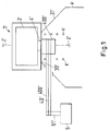
- the centrifuge 1 ' comprises a centrifuge drum 3' which has a drive shaft 4 'lying in a rotation axis 2' of the centrifuge drum 3 ', a drive belt 40' non-rotatably connecting the drive shaft 4 'to a drive axle 51' of an electric rotary drive 5 ', so that in the operating state the centrifuge drum 3 'is set in rapid rotation by the electric rotary drive 5' via the drive shaft 51 ', the drive belt 40' and finally via the drive shaft 4 '.
- the dehumidified solid cake K ' is thereby discharged through an opening 30' of the centrifuge drum 3 'downwards through an ejection hopper 31' from the centrifuge drum 3 ', wherein in particular in high-purity products, e.g. for pharmaceutical products, the discharge funnel 31 'leads directly into a clean room R'.
- the drive shaft 4 ' to which the drive belt 40' engages, is arranged concentrically in the discharge funnel 31 'and the drive belt 40' and the drive shaft 4 'are encapsulated in a housing 400' as a rule, so that the interior of the centrifuge drum 3 ' and the clean room R 'are securely sealed against all components of the drive system.
- the entire construction of centrifuge and electric rotary drive occupies a considerable space.
- the drive shaft is under a considerable tensile or bending load.
- the drive shaft of the centrifuge drum must be stored in a complex storage device with multiple axially offset bearings, usually at least three bearings are provided in a known storage device, which are arranged at a great axial distance from each other, so that under strong tensile or Bending load standing drive shaft can be stored safely.
- the bearings are large in size, have a high weight and are complicated in construction.
- the correct tension of the drive belt is difficult to adjust, and must be corrected after a certain number of operating hours.
- the drive belt develops a high level of noise during operation, which is not only unpleasant, but also questionable for reasons of safety at work, since the operating personnel are exposed to high noise levels, which can lead to permanent damage to health.
- the object of the invention is therefore to propose an improved centrifuge which largely avoids the disadvantages known from the prior art.
- the invention thus relates to a centrifuge for separating a mixture into a solids cake and into a liquid phase, comprising a rotatable about a rotation axis centrifuge drum, wherein the centrifuge drum is rotatably connected via a lying in the axis of rotation drive shaft with an electric rotary drive for rotational drive of the centrifuge drum.
- a central drive shaft of the electric rotary drive is connected in a rotationally fixed manner axially aligned with the drive shaft of the centrifuge drum.
- the rotary electric drive is encapsulated by an encapsulation, so that within the enclosure an atmosphere of inert gas can be produced.
- the drive shaft is preferably mounted in first bearing devices and a second bearing device of a bearing device, wherein the first bearing device is arranged offset in relation to the second bearing device in the axial direction along the axis of rotation.
- the first bearing device and / or the second bearing device is a tapered roller bearing.
- the bearing device may comprise in a conventional manner, a biasing means for biasing the first bearing means and / or the second bearing means, wherein the biasing means is preferably formed by a spring.
- a cooling device For cooling the rotary drive and / or for cooling the storage device, a cooling device can be provided very advantageously, wherein the cooling device for exchanging coolant preferably comprises a coolant supply and a coolant discharge and the coolant is often water in practice.
- the storage device and / or the cooling device is also provided within the enclosure.
- a sealant for example in the form of a seal for sealing the rotary drive with respect to a product space and / or an ambient atmosphere, is preferably provided on the encapsulation so that, for example, no highly explosive solvent can penetrate into the encapsulation.
- the centrifuge is a discontinuous centrifuge, preferably the centrifuge is a peeler centrifuge, in particular a vertical and / or a horizontal peeler centrifuge.
- Fig. 1 shows a schematic representation of a known from the prior art horizontal peeler centrifuge with laterally mounted electric rotary drive. There Fig. 1 has already been discussed in detail at the beginning, a further discussion of this state of the art is unnecessary at this point.
- Fig. 2 is schematically sketched a horizontal peeler centrifuge according to the present invention, wherein Fig. 3 a little more detailed the bearing device of the Fig. 2 shows. It goes without saying that the invention is not based on peeler centrifuges or even on horizontal peeler centrifuges Fig. 2 respectively. Fig. 3 is limited. Rather, an electric drive according to the present invention can also be advantageously used in other types of centrifuge, which are all well known to the person skilled in the art.
- the inventive centrifuge 1 for separating a mixture into a solid cake and into a liquid phase, comprises a rotatable about a rotation axis 2 centrifuge drum 3, the centrifuge drum 3 is connected via a lying in the rotation axis 2 drive shaft 4 with an electric rotary drive 5 for rotational drive of the centrifuge drum 3 directly rotatably connected ,
- a central drive shaft 51 of the electric rotary drive 5 is axially connected in a rotationally fixed manner to the drive shaft 4 of the centrifuge drum 3.
- the electric rotary drive 5 which may be, for example, a commercially available electric motor 5 for driving a machine tool, such as for driving a lathe, is connected with its drive shaft 51 directly and axially aligned with the drive shaft 4 of the centrifuge drum 3.
- the bearing device 8 with first bearing means 81 and second bearing means 82 which are designed here as tapered roller bearings 81, 82, in which the drive shaft 4 of the centrifuge drum 3 is mounted, together with the electric rotary drive 5 in an encapsulation 6 is encapsulated such that the interior the encapsulation 6, so in particular the electric rotary drive 5 and the bearing device 8 are securely sealed against the external environment.
- the interior of the enclosure 6 is flooded with an inert gas 7, for example with nitrogen 7 or a noble gas 7, so that any risk of explosion, for example by sparking in the electric rotary drive. 5 is excluded.
- the inert gas 7 is introduced via the schematically indicated by the arrow 7 feed into the enclosure 6.
- a cooling device 9 is provided, in which water is supplied in the encapsulation 6 via the coolant supply 91 and coolant via the coolant discharge 92 in the present example as a coolant is dissipated.
- connection 11 can be seen, can be added to the other operating materials, such as lubricant and / or discharged, and an electrical connection 12 via the electric rotary drive 5 electrical energy can be supplied or via the example, electrical control signals or also sensor signals of all kinds can be exchanged.
- Fig. 3 is the storage facility according to Fig. 2 shown in more detail.
- the drum hub 300 via which the drive shaft 4 in a conventional manner rotatably connected to the centrifuge drum 3 and the two tapered roller bearings 81, 82, in which the drive shaft 4 is securely stored. Since no tensile forces acting on the drive shaft 4 by a drive belt, the two tapered roller bearings 81, 82 are arranged in a relatively small distance in the axial direction along the axis of rotation 2 to each other, whereby the bearing device is less expensive, more compact and thus lighter, cheaper and less susceptible to interference, as the storage devices known from the prior art.
- Fig. 3 is the interior of the enclosure 6 while sealed with special seals 10 safe to the outside.
- the advantage of the present invention are obvious: the fact that no tensile forces act on the storage of the centrifuge drum, a small bearing clearance can be achieved through the use of tapered roller bearings, resulting in a very compact design of the bearing device.
- the drive shaft of the engine is only torsioned.
- the assembly and disassembly of the drive and bearing device is considerably simplified and the maintenance intervals are significantly greater, since the loads on drive and storage are significantly reduced.
- the machine dimensions are significantly reduced and a low center of gravity of the centrifuge is achieved, which is also symmetrical in the machine axis, resulting in a significantly better running behavior and less vibration in the operating condition.
- the drive noise is drastically reduced and the risk of accidents is significantly reduced, because all moving parts of the centrifuge are completely and safely encapsulated. Since no drive belt must be brought to the drive shaft, the centrifuge drum can be performed with symmetrical spokes, which also increases the smoothness significantly.
Landscapes
- Centrifugal Separators (AREA)
Description
- Die Erfindung betrifft eine Zentrifuge gemäss dem Oberbegriff des unabhängigen Anspruchs 1. Eine solche Zentrifuge ist beispielsweise aus
EP-A-1849524 bekannt. - Zur Trocknung feuchter Substanzen oder feuchter Substanzgemische sind Zentrifugen in den verschiedensten Ausführungsformen weit verbreitet und werden auf den verschiedensten Gebieten eingesetzt. So kommen beispielsweise zur Trocknung hochreiner pharmazeutischer Produkte diskontinuierlich arbeitende Zentrifugen, wie Schälzentrifugen, bevorzugt zum Einsatz, während insbesondere dann, wenn kontinuierlich grosse Mengen eines fest-flüssig Gemischs getrennt werden sollen, kontinuierlich arbeitende Schubzentrifugen vorteilhaft eingesetzt werden. Dabei kommen je nach Anforderung ein- oder mehrstufige Schubzentrifugen, sowie sogenannte Doppelschubzentrifugen zum Einsatz.
- Schälzentrifugen, insbesondere horizontale Schälzentrifugen werden von einem Drehantrieb, meist von einem Elektromotor angetrieben, der zum Beispiel über einen Zahnriemen mit einer Antriebswelle der Zentrifugentrommel der Zentrifuge verbunden ist und so die Zentrifugentrommel in schnelle Rotation versetzt.
- In
Fig. 1 ist eine solche bekannte Anordnung stark schematisch dargestellt. Die Zentrifuge 1' umfasst eine Zentrifugentrommel 3', die über eine in einer Drehachse 2' der Zentrifugentrommel 3' liegenden Antriebswelle 4' verfügt, wobei ein Antriebsriemen 40' die Antriebswelle 4' mit einer Antriebsachse 51' eines elektrischen Drehantriebs 5' drehfest verbindet, so dass im Betriebszustand die Zentrifugentrommel 3' vom elektrischen Drehantrieb 5' über die Antriebsachse 51', den Antriebsriemen 40' und schliesslich über die Antriebswelle 4' in schnelle Rotation versetzt wird. - Der entfeuchtete Feststoffkuchen K' wird dabei durch eine Öffnung 30' der Zentrifugentrommel 3' darstellungsgemäss nach unten durch einen Auswurftrichter 31' aus der Zentrifugentrommel 3' ausgebracht, wobei insbesondere bei hochreinen Produkten, z.B. bei pharmazeutischen Produkten, der Auswurftrichter 31' direkt in einen Reinraum R' führt.
- Die Antriebswelle 4', an die der Antriebsriemen 40' angreift, ist dabei konzentrisch im Auswurftrichter 31' angeordnet und der Antriebsriemen 40' und die Antriebswelle 4' sind dabei in Regel in einem Gehäuse 400' gekapselt, so dass das Innere der Zentrifugentrommel 3' und der Reinraum R' sicher gegen alle Komponenten des Antriebssystems abgedichtet sind.
- Diese vom Aufbau her recht komplizierte Lösung war bisher notwendig, da, neben anderen dem Fachmann wohl bekannten Gründen, der elektrische Drehantrieb 5' möglichst von aus der Zentrifugentrommel austretenden Gasen isoliert werden musste. Bei einer ganzen Reihe von Produktklassen bzw. Entfeuchtungsprozessen werden in der Zentrifugentrommel 3' Lösungsmittel verwendet, bzw. das zu entfeuchtende Produkt enthält solche Lösungsmittel, die zusammen mit Luftsauerstoff hochexplosive gasförmige Gemische bilden können, die z.B. durch Funkenschlag im elektrischen Drehantrieb 5' zur Explosion gebracht werden könnten.
- Daher war es, neben Gründen der Sauberkeit, der Hygiene usw., bei den bekannten Zentrifugen bisher zwingend notwendig, den elektrischen Drehantrieb 5' derart entfernt von der Zentrifugentrommel 3' zu platzieren und von deren Innerem zu isolieren, dass sowohl Kontaminationen durch den elektrischen Drehantrieb 5' als auch jegliche Explosionsgefahr ausgeschlossen waren.
- Diese Sicherheit wurde jedoch mit einer ganzen Reihe gravierender Nachteile erkauft.
- So nimmt der gesamte Aufbau aus Zentrifuge und elektrischem Drehantrieb einen beachtlichen Raum ein. Durch den unter erheblicher Vorspannung stehenden Antriebsriemen steht die Antriebswelle unter einer erheblichen Zug- bzw. Biegebelastung. Um diese auszugleichen muss die Antriebswelle der Zentrifugentrommel in einer aufwendigen Lagervorrichtung mit mehreren axial versetzten Lagern gelagert werden, wobei in der Regel mindestens drei Lager in einer bekannten Lagervorrichtung vorgesehen sind, die in grossem axialen Abstand voneinander angeordnet werden, damit die unter starker Zug- bzw. Biegebelastung stehende Antriebswelle sicher gelagert werden kann. Dadurch werden die Lager gross in den Abmessungen, haben ein hohes Gewicht und sind kompliziert im Aufbau. Ausserdem ist die korrekte Spannung des Antriebsriemens schwierig einzustellen, und muss nach einer gewissen Zahl von Betriebsstunden nachkorrigiert werden.
- Insgesamt ist die Konstruktion aus Antriebsaufbau mit Motorplatte, Antriebsriemen, Riemenscheiben, Schutzblechen usw. sehr aufwändig und insgesamt ungünstig, da der Schwerpunkt des Gesamtsystems ausserhalb der Maschinenachse liegt, was sich ausserordentlich negativ auf die Dämpfung des gesamten Systems auswirkt.
- Nicht zuletzt entwickelt der Antriebsriemen im Betrieb einen hohen Geräuschpegel, was nicht nur unangenehm, sondern auch aus Gründen der Arbeitssicherheit bedenklich ist, da das Bedienpersonal hohen Geräuschbelastungen ausgesetzt ist, die auf Dauer zu gesundheitlichen Schäden führen können.
- Die Aufgabe der Erfindung ist es daher, eine verbesserte Zentrifuge vorzuschlagen, die die aus dem Stand der Technik bekannten Nachteile weitgehend vermeidet.
- Die diese Aufgabe lösenden Gegenstände der Erfindung sind durch die Merkmale des unabhängigen Anspruchs 1 gekennzeichnet.
- Die abhängigen Ansprüche beziehen sich auf besonders vorteilhafte Ausführungsformen der Erfindung.
- Die Erfindung betrifft somit eine Zentrifuge zur Trennung eines Gemischs in einen Feststoffkuchen und in eine Flüssigphase, umfassend eine um eine Drehachse rotierbare Zentrifugentrommel, wobei die Zentrifugentrommel über eine in der Drehachse liegende Antriebswelle mit einem elektrischen Drehantrieb zum rotatorischen Antrieb der Zentrifugentrommel drehfest verbunden ist. Erfindungsgemäss ist eine zentrale Antriebsachse des elektrischen Drehantriebs axial fluchtend mit der Antriebswelle der Zentrifugentrommel drehfest verbunden.
- In einem für die Praxis besonders wichtigen Ausführungsbeispiel ist der elektrische Drehantrieb durch eine Kapselung gekapselt, so dass innerhalb der Kapselung eine Atmosphäre aus Inertgas herstellbar ist.
- Dabei ist die Antriebswelle bevorzugt in ersten Lagereinrichtungen und einer zweiten Lagereinrichtung einer Lagervorrichtung gelagert, wobei die erste Lagereinrichtung in Bezug auf die zweite Lagereinrichtung in axialer Richtung entlang der Drehachse versetzt angeordnet ist. Im Speziellen ist die erste Lagereinrichtung und / oder die zweite Lagereinrichtung ein Kegelrollenlager.
- Um eine höhere Laufruhe der Zentrifugentrommel zu erreichen und den Verschleiss in den Lagern zu minimieren, kann die Lagervorrichtung in an sich bekannter Weise eine Vorspanneinrichtung zur Vorspannung der ersten Lagereinrichtung und / oder der zweiten Lagereinrichtung umfassen, wobei die Vorspanneinrichtung bevorzugt durch eine Feder gebildet ist.
- Zur Kühlung des Drehantriebs und / oder zur Kühlung der Lagervorrichtung kann sehr vorteilhaft eine Kühleinrichtung vorgesehen sein, wobei die Kühleinrichtung zum Austausch von Kühlmittel bevorzugt eine Kühlmittelzuführung und eine Kühlmittelableitung umfasst und das Kühlmittel in der Praxis häufig Wasser ist.
- Im Speziellen ist die Lagervorrichtung und / oder die Kühleinrichtung ebenfalls innerhalb der Kapselung vorgesehen.
- In einem für die Praxis wichtigen Ausführungsbeispiel ist bevorzugt an der Kapselung ein Dichtmittel, zum Beispiel in Form einer Dichtung zur Abdichtung des Drehantriebs gegenüber einem Produktraum und / oder gegenüber einer Umgebungsatmosphäre vorgesehen, so dass zum Beispiel kein hochexplosives Lösungsmittel in die Kapselung eindringen kann.
- Im Speziellen ist die Zentrifuge eine diskontinuierlich arbeitende Zentrifuge, bevorzugt ist die Zentrifuge eine Schälzentrifuge, insbesondere eine vertikale und / oder eine horizontale Schälzentrifuge.
- Die Erfindung wird im Folgenden an Hand der schematischen Zeichnung näher erläutert. Es zeigen:
- Fig. 1
- schematisch eine aus dem Stand der Technik bekannte Zentrifuge;
- Fig. 2
- eine erfindungsgemässe Schälzentrifuge;
- Fig. 3
- Lagervorrichtung mit Antriebswelle einer erfindungsgemässen Schälzentrifuge;
-
Fig. 1 zeigt in schematischer Darstellung eine aus dem Stand der Technik bekannte horizontale Schälzentrifuge mit seitlich angebautem elektrischem Drehantrieb. DaFig. 1 bereits eingangs ausführlich besprochen wurde, erübrigt sich an dieser Stelle eine weitere Diskussion dieses Stands der Technik. - In
Fig. 2 ist schematisch eine horizontale Schälzentrifuge gemäss der vorliegenden Erfindung skizziert, wobeiFig. 3 etwas detaillierter die Lagervorrichtung derFig. 2 zeigt. Dabei versteht sich von selbst, dass die Erfindung nicht auf Schälzentrifugen oder gar auf horizontale Schälzentrifugen gemässFig. 2 bzw.Fig. 3 beschränkt ist. Vielmehr kann ein elektrischer Antrieb gemäss der vorliegenden Erfindung auch bei anderen Zentrifugentypen, die dem Fachmann sämtlich wohl bekannt sind, vorteilhaft zum Einsatz kommen. - Zur besseren Unterscheidung der vorliegenden Erfindung von den aus dem Stand der Technik bekannten Zentrifugen gemäss
Fig. 1 , tragen Bezugszeichen der in denFig. 2 undFig. 3 dargestellten Merkmale erfindungsgemässer Zentrifugen kein Hochkomma, während die Bezugszeichen derFig. 1 , die sich auf den Stand der Technik bezieht, mit Hochkomma versehen sind. - Die erfindungsgemässe Zentrifuge 1 gemäss
Fig. 1 zur Trennung eines Gemischs in einen Feststoffkuchen und in eine Flüssigphase, umfasst eine um eine Drehachse 2 rotierbare Zentrifugentrommel 3, wobei die Zentrifugentrommel 3 über eine in der Drehachse 2 liegende Antriebswelle 4 mit einem elektrischen Drehantrieb 5 zum rotatorischen Antrieb der Zentrifugentrommel 3 unmittelbar drehfest verbunden ist. Gemäss der vorliegenden Erfindung ist eine zentrale Antriebsachse 51 des elektrischen Drehantriebs 5 axial fluchtend mit der Antriebswelle 4 der Zentrifugentrommel 3 drehfest verbunden. - Das heisst, der elektrische Drehantrieb 5, der zum Beispiel ein handelsüblicher Elektromotor 5 zum Antrieb einer Werkzeugmaschine, wie zum Beispiel zum Antrieb einer Drehbank sein kann, ist mit seiner Antriebsachse 51 direkt und axial fluchtend mit der Antriebswelle 4 der Zentrifugentrommel 3 verbunden.
- Dass ist dadurch möglich, dass im speziellen Beispiel der
Fig. 2 die Lagervorrichtung 8 mit erster Lagereinrichtung 81 und zweiter Lagereinrichtung 82, die hier als Kegelrollenlager 81, 82 ausgebildet sind, in welchen die Antriebswelle 4 der Zentrifugentrommel 3 gelagert ist, zusammen mit dem elektrischen Drehantrieb 5 in einer Kapselung 6 derart gekapselt ist, dass das Innere der Kapselung 6, also insbesondere der elektrische Drehantrieb 5 und die Lagervorrichtung 8 sicher gegen die äussere Umgebung abgedichtet sind. - Das Innere der Kapselung 6 ist mit einem Inertgas 7, zum Beispiel mit Stickstoff 7 oder einem Edelgas 7 geflutet, so dass jegliche Explosionsgefahr, zum Beispiel durch Funkenbildung im elektrischen Drehantrieb 5 ausgeschlossen ist. Das Inertgas 7 wird dabei über die schematisch mit dem Pfeil 7 bezeichnete Zuführung in die Kapselung 6 eingeführt.
- Da sich im Betriebszustand erhebliche Mengen von Wärme im elektrischen Drehantrieb 5 bzw. in der Lagervorrichtung 8 bilden können, ist eine Kühleinrichtung 9 vorgesehen, bei der im vorliegenden Beispiel als Kühlmittel Wasser in die Kapselung 6 über die Kühlmittelzuführung 91 zugeführt und über die Kühlmittelableitung 92 wieder abgeführt wird.
- Des weiteren ist eine Verbindung 11 zu erkennen, über die weitere Betriebsstoffe, wie zum Beispiel Schmiermittel zu- und / oder abgeführt werden kann, und eine elektrische Verbindung 12 über die dem elektrischen Drehantrieb 5 elektrische Energie zuführbar ist oder über die zum Beispiel elektrische Steuersignale oder auch Sensorsignale aller Art ausgetauscht werden können.
- In
Fig. 3 ist die Lagereinrichtung gemässFig. 2 noch etwas detaillierter dargestellt. Deutlich zu erkennen ist die Trommelnabe 300 über die die Antriebswelle 4 in an sich bekannter Weise drehfest mit der Zentrifugentrommel 3 verbunden ist und die beiden Kegelrollenlager 81, 82, in denen die Antriebswelle 4 sicher gelagertes ist. Da keine Zugkräfte durch einen Antriebsriemen auf die Antriebswelle 4 wirken, sind die beiden Kegelrollenlager 81, 82 in verhältnismässig kleinem Abstand in axialer Richtung entlang der Drehachse 2 zueinander angeordnet, wodurch die Lagervorrichtung weniger aufwändig, kompakter und damit leichter, billiger und weniger störanfällig ist, als die aus dem Stand der Technik bekannten Lagervorrichtungen. - In
Fig. 3 ist das Innere der Kapselung 6 dabei mit speziellen Dichtungen 10 sicher nach aussen abgedichtet. - Zusammenfassend liegen die Vorteil der vorliegenden Erfindung klar auf der Hand: Dadurch, dass keine Zugkräfte auf die Lagerung der Zentrifugentrommel wirken, kann ein kleiner Lagerabstand durch den Einsatz von Kegelrollenlagern erreicht werden, was zu einer sehr kompakten Ausführung der Lagervorrichtung führt. Die Antriebswelle des Motors ist nur noch torsionsbelastet. Die Montage und Demontage von Antrieb und Lagervorrichtung ist erheblich vereinfacht und die Wartungsintervalle sind deutlich grösser, da die Belastungen auf Antrieb und Lagerung wesentlich reduziert sind. Die Maschinenabmessungen insgesamt sind deutlich verkleinert und es wird ein tiefer Schwerpunkt der Zentrifuge insgesamt erreicht, der zudem symmetrisch in der Maschinenachse liegt, was zu einem deutlich besseren Laufverhalten und weniger Vibrationen im Betriebszustand führt. Die Antriebsgeräusche sind drastisch reduziert und die Unfallgefahr ist deutlich herabgesetzt, weil alle sich bewegenden Teile der Zentrifuge vollständig und sicher gekapselt sind. Da kein Antriebsriemen an die Antriebswelle herangeführt werden muss, kann die Zentrifugentrommel mit symmetrischen Speichen ausgeführt werden, was ebenfalls die Laufruhe deutlich erhöht.
- Insgesamt wird Platz und Gewicht durch die kompaktere Bauweise eingespart und durch den Einsatz der erfindunsgemässen Zentrifuge können die Betriebskosten, insbesondere die Energiekosten und die Wartungskosten signifikant gesenkt werden.
Claims (12)
- Zentrifuge zur Trennung eines Gemischs in einen Feststoffkuchen und in eine Flüssigphase, umfassend eine um eine Drehachse (2) rotierbare Zentrifugentrommel (3), wobei die Zentrifugentrommel (3) über eine in der Drehachse (2) liegende Antriebswelle (4) mit einem elektrischen Drehantrieb (5) zum rotatorischen Antrieb der Zentrifugentrommel (3) drehfest verbunden ist, und eine zentrale Antriebsachse (51) des elektrischen Drehantriebs (5) axial fluchtend mit der Antriebswelle (4) der Zentrifugentrommel (3) drehfest verbunden ist, dadurch gekennzeichnet, dass die Antriebswelle (4) in ersten Lagereinrichtungen (81) und einer zweiten Lagereinrichtung (82) einer Lagervorrichtung (8) gelagert ist, und die erste Lagereinrichtung (81) in Bezug auf die zweite Lagereinrichtung (82) in axialer Richtung entlang der Drehachse (2) versetzt angeordnet ist, und die erste Lagereinrichtung (81) und / oder die zweite Lagereinrichtung (82) ein Kegelrollenlager (81, 82) ist.
- Zentrifuge nach Anspruch 1, wobei der elektrische Drehantrieb (5) durch eine Kapselung (6) gekapselt ist, so dass innerhalb der Kapselung (6) eine Atmosphäre aus Innertgas (7) herstellbar ist.
- Zentrifuge nach einem der Ansprüche 1 oder 2, wobei die Lagervorrichtung (8) eine Vorspanneinrichtung zur Vorspannung der erste Lagereinrichtung (81) und / oder der zweiten Lagereinrichtung (82) umfasst.
- Zentrifuge nach Anspruch 3, wobei die Vorspanneinrichtung durch eine Feder gebildet ist.
- Zentrifuge nach einem der vorangehenden Ansprüche, wobei zur Kühlung des Drehantriebs (5) und / oder zur Kühlung der Lagervorrichtung (8) eine Kühleinrichtung (9) vorgesehen ist.
- Zentrifuge nach Anspruch 5, wobei die Kühleinrichtung (9) zum Austausch von Kühlmittel eine Kühlmittelzuführung (91) und eine Kühlmittelableitung (92) umfasst.
- Zentrifuge nach einem der Ansprüche 5 oder 6, wobei das Kühlmittel Wasser ist.
- Zentrifuge nach einem der vorangehenden Ansprüche, wobei die Lagervorrichtung (8) und / oder die Kühleinrichtung (9) innerhalb der Kapselung (6) vorgesehen ist.
- Zentrifuge nach einem der vorangehenden Ansprüche, wobei ein Dichtmittel (10) zur Abdichtung des Drehantriebs (5) gegenüber einem Produktraum und / oder gegenüber einer Umgebungsatmosphäre vorgesehen ist.
- Zentrifuge nach Anspruch 9, wobei das Dichtmittel (10) an der Kapselung (6) vorgesehen ist.
- Zentrifuge nach einem der vorangehenden Ansprüche, wobei die Zentrifuge eine diskontinuierlich arbeitende Zentrifuge ist.
- Zentrifuge nach einem der vorangehenden Ansprüche, wobei die Zentrifuge eine Schälzentrifuge, insbesondere eine horizontale Schälzentrifuge ist.
Priority Applications (1)
| Application Number | Priority Date | Filing Date | Title |
|---|---|---|---|
| EP09173004.4A EP2181770B1 (de) | 2008-10-30 | 2009-10-14 | Zentrifuge |
Applications Claiming Priority (2)
| Application Number | Priority Date | Filing Date | Title |
|---|---|---|---|
| EP08167973 | 2008-10-30 | ||
| EP09173004.4A EP2181770B1 (de) | 2008-10-30 | 2009-10-14 | Zentrifuge |
Publications (2)
| Publication Number | Publication Date |
|---|---|
| EP2181770A1 EP2181770A1 (de) | 2010-05-05 |
| EP2181770B1 true EP2181770B1 (de) | 2016-10-05 |
Family
ID=40394175
Family Applications (1)
| Application Number | Title | Priority Date | Filing Date |
|---|---|---|---|
| EP09173004.4A Not-in-force EP2181770B1 (de) | 2008-10-30 | 2009-10-14 | Zentrifuge |
Country Status (2)
| Country | Link |
|---|---|
| EP (1) | EP2181770B1 (de) |
| ES (1) | ES2601604T3 (de) |
Families Citing this family (2)
| Publication number | Priority date | Publication date | Assignee | Title |
|---|---|---|---|---|
| DE102013105006A1 (de) * | 2012-05-22 | 2013-11-28 | Gea Mechanical Equipment Gmbh | Antriebsvorrichtung für eine Separatoranordnung |
| DE102014018058A1 (de) * | 2014-12-05 | 2016-06-09 | Guntram Krettek | Zentrifuge mit temperiertem Lager |
Family Cites Families (8)
| Publication number | Priority date | Publication date | Assignee | Title |
|---|---|---|---|---|
| GB308033A (en) * | 1928-02-06 | 1929-03-21 | Broadbent & Sons Ltd Thomas | An improvement in or relating to centrifugal machines |
| US3539096A (en) * | 1967-04-27 | 1970-11-10 | Dow Oliver Inc | Hy-g centrifuge |
| US3604769A (en) * | 1968-09-23 | 1971-09-14 | Cryogenic Technology Inc | Temperature-controlled spindle for centrifuges and similar apparatus |
| US4205779A (en) * | 1979-03-14 | 1980-06-03 | Beckman Instruments, Inc. | Pressure bypass ports for an ultracentrifuge drive system in a vacuum environment |
| US4234123A (en) * | 1979-07-05 | 1980-11-18 | Force Control Industries, Inc. | Centrifuge drive system |
| DE3343938A1 (de) * | 1983-12-05 | 1985-06-13 | Krauss-Maffei AG, 8000 München | Lagerabdichtung fuer eine zentrifuge |
| US5004540A (en) * | 1989-12-01 | 1991-04-02 | Ketema Process Equipment Division | Invertible filter-type centrifuge with improved bearing and seal assembly |
| ES2594184T3 (es) * | 2006-04-25 | 2016-12-16 | Ferrum Ag | Disposición de junta de estanqueidad para una centrífuga |
-
2009
- 2009-10-14 EP EP09173004.4A patent/EP2181770B1/de not_active Not-in-force
- 2009-10-14 ES ES09173004.4T patent/ES2601604T3/es active Active
Also Published As
| Publication number | Publication date |
|---|---|
| EP2181770A1 (de) | 2010-05-05 |
| ES2601604T3 (es) | 2017-02-15 |
Similar Documents
| Publication | Publication Date | Title |
|---|---|---|
| EP0936948B1 (de) | Stülpfilterzentrifuge | |
| EP1603679A1 (de) | Stülpfilterzentrifuge | |
| EP3608025A1 (de) | Vorrichtung zum kühlen und mahlen von aufbereitungsgut | |
| DE102011079555B4 (de) | Antriebsanordnung für eine Vertikal-Rollenmühle | |
| EP2181770A1 (de) | Zentrifuge | |
| DE102010031252A1 (de) | Substratbehandlungseinrichtung | |
| DE102015013141B4 (de) | Antriebseinheit für ein Flurförderfahrzeug | |
| DE3545828A1 (de) | Verfahren und einrichtung zum betrieb einer mahlanlage | |
| DE102010031259B4 (de) | Stützeinrichtung für eine Magnetronanordnung mit einem rotierenden Target | |
| DE3703984A1 (de) | Einrichtung zur zerstoerung von halogenierten aromaten, wie chlorierte dibenzodioxine, chlorierte dibenzofurane oder dgl., in flugaschen aus abfallverbrennungsanlagen | |
| EP0734987A2 (de) | Antrieb für ein Falzmesser in einer Falztrommel | |
| DE2630206A1 (de) | Radantrieb fuer flurfoerderfahrzeuge | |
| EP3271076B1 (de) | Zerkleinerungsvorrichtung | |
| DE2105507A1 (de) | Selbsttätige Unwuchtausgleichsvor richtung | |
| DE112022002181T5 (de) | Batterieförderband | |
| DE3430508C2 (de) | ||
| EP1852189A2 (de) | Anlagenkonzept für Mühlen und Sichter mit Magnetlagerspindelantrieb | |
| EP0129038A1 (de) | Lageranordnung für Lager zum Betrieb unter Wasser und in schlammartigen Medien | |
| DE102013105006A1 (de) | Antriebsvorrichtung für eine Separatoranordnung | |
| EP0038909A1 (de) | Windsichter | |
| EP0313756B1 (de) | Reaktor zum Behandeln von Schüttgütern oder dergleichen | |
| DD161249A3 (de) | Siebgranulator zur selektiven zerkleinerung | |
| EP0517178A1 (de) | Konus-Trocker oder -Mischer mit Schwenkarmgetriebe und Dichtungsanordnung | |
| DE2655266A1 (de) | Kolloidmuehle, insbesondere fuer den laborbedarf | |
| CH641536A5 (en) | Safety detent coupling featuring angularly accurate reengagement after 360 DEG |
Legal Events
| Date | Code | Title | Description |
|---|---|---|---|
| PUAI | Public reference made under article 153(3) epc to a published international application that has entered the european phase |
Free format text: ORIGINAL CODE: 0009012 |
|
| AK | Designated contracting states |
Kind code of ref document: A1 Designated state(s): AT BE BG CH CY CZ DE DK EE ES FI FR GB GR HR HU IE IS IT LI LT LU LV MC MK MT NL NO PL PT RO SE SI SK SM TR |
|
| AX | Request for extension of the european patent |
Extension state: AL BA RS |
|
| 17P | Request for examination filed |
Effective date: 20101105 |
|
| 17Q | First examination report despatched |
Effective date: 20101207 |
|
| GRAP | Despatch of communication of intention to grant a patent |
Free format text: ORIGINAL CODE: EPIDOSNIGR1 |
|
| INTG | Intention to grant announced |
Effective date: 20160429 |
|
| GRAS | Grant fee paid |
Free format text: ORIGINAL CODE: EPIDOSNIGR3 |
|
| GRAA | (expected) grant |
Free format text: ORIGINAL CODE: 0009210 |
|
| AK | Designated contracting states |
Kind code of ref document: B1 Designated state(s): AT BE BG CH CY CZ DE DK EE ES FI FR GB GR HR HU IE IS IT LI LT LU LV MC MK MT NL NO PL PT RO SE SI SK SM TR |
|
| REG | Reference to a national code |
Ref country code: GB Ref legal event code: FG4D Free format text: NOT ENGLISH |
|
| REG | Reference to a national code |
Ref country code: CH Ref legal event code: EP Ref country code: CH Ref legal event code: PK Free format text: BERICHTIGUNG INHABER Ref country code: CH Ref legal event code: NV Representative=s name: INTELLECTUAL PROPERTY SERVICES GMBH, CH |
|
| REG | Reference to a national code |
Ref country code: AT Ref legal event code: REF Ref document number: 834157 Country of ref document: AT Kind code of ref document: T Effective date: 20161015 |
|
| REG | Reference to a national code |
Ref country code: FR Ref legal event code: PLFP Year of fee payment: 8 |
|
| REG | Reference to a national code |
Ref country code: IE Ref legal event code: FG4D Free format text: LANGUAGE OF EP DOCUMENT: GERMAN |
|
| REG | Reference to a national code |
Ref country code: DE Ref legal event code: R096 Ref document number: 502009013163 Country of ref document: DE |
|
| REG | Reference to a national code |
Ref country code: NL Ref legal event code: MP Effective date: 20161005 |
|
| REG | Reference to a national code |
Ref country code: LT Ref legal event code: MG4D |
|
| REG | Reference to a national code |
Ref country code: ES Ref legal event code: FG2A Ref document number: 2601604 Country of ref document: ES Kind code of ref document: T3 Effective date: 20170215 |
|
| PG25 | Lapsed in a contracting state [announced via postgrant information from national office to epo] |
Ref country code: BE Free format text: LAPSE BECAUSE OF NON-PAYMENT OF DUE FEES Effective date: 20161031 Ref country code: LV Free format text: LAPSE BECAUSE OF FAILURE TO SUBMIT A TRANSLATION OF THE DESCRIPTION OR TO PAY THE FEE WITHIN THE PRESCRIBED TIME-LIMIT Effective date: 20161005 |
|
| PG25 | Lapsed in a contracting state [announced via postgrant information from national office to epo] |
Ref country code: GR Free format text: LAPSE BECAUSE OF FAILURE TO SUBMIT A TRANSLATION OF THE DESCRIPTION OR TO PAY THE FEE WITHIN THE PRESCRIBED TIME-LIMIT Effective date: 20170106 Ref country code: LT Free format text: LAPSE BECAUSE OF FAILURE TO SUBMIT A TRANSLATION OF THE DESCRIPTION OR TO PAY THE FEE WITHIN THE PRESCRIBED TIME-LIMIT Effective date: 20161005 Ref country code: NO Free format text: LAPSE BECAUSE OF FAILURE TO SUBMIT A TRANSLATION OF THE DESCRIPTION OR TO PAY THE FEE WITHIN THE PRESCRIBED TIME-LIMIT Effective date: 20170105 Ref country code: SE Free format text: LAPSE BECAUSE OF FAILURE TO SUBMIT A TRANSLATION OF THE DESCRIPTION OR TO PAY THE FEE WITHIN THE PRESCRIBED TIME-LIMIT Effective date: 20161005 |
|
| PG25 | Lapsed in a contracting state [announced via postgrant information from national office to epo] |
Ref country code: PL Free format text: LAPSE BECAUSE OF FAILURE TO SUBMIT A TRANSLATION OF THE DESCRIPTION OR TO PAY THE FEE WITHIN THE PRESCRIBED TIME-LIMIT Effective date: 20161005 Ref country code: PT Free format text: LAPSE BECAUSE OF FAILURE TO SUBMIT A TRANSLATION OF THE DESCRIPTION OR TO PAY THE FEE WITHIN THE PRESCRIBED TIME-LIMIT Effective date: 20170206 Ref country code: NL Free format text: LAPSE BECAUSE OF FAILURE TO SUBMIT A TRANSLATION OF THE DESCRIPTION OR TO PAY THE FEE WITHIN THE PRESCRIBED TIME-LIMIT Effective date: 20161005 Ref country code: FI Free format text: LAPSE BECAUSE OF FAILURE TO SUBMIT A TRANSLATION OF THE DESCRIPTION OR TO PAY THE FEE WITHIN THE PRESCRIBED TIME-LIMIT Effective date: 20161005 Ref country code: HR Free format text: LAPSE BECAUSE OF FAILURE TO SUBMIT A TRANSLATION OF THE DESCRIPTION OR TO PAY THE FEE WITHIN THE PRESCRIBED TIME-LIMIT Effective date: 20161005 Ref country code: IS Free format text: LAPSE BECAUSE OF FAILURE TO SUBMIT A TRANSLATION OF THE DESCRIPTION OR TO PAY THE FEE WITHIN THE PRESCRIBED TIME-LIMIT Effective date: 20170205 |
|
| REG | Reference to a national code |
Ref country code: DE Ref legal event code: R097 Ref document number: 502009013163 Country of ref document: DE |
|
| REG | Reference to a national code |
Ref country code: IE Ref legal event code: MM4A |
|
| PG25 | Lapsed in a contracting state [announced via postgrant information from national office to epo] |
Ref country code: RO Free format text: LAPSE BECAUSE OF FAILURE TO SUBMIT A TRANSLATION OF THE DESCRIPTION OR TO PAY THE FEE WITHIN THE PRESCRIBED TIME-LIMIT Effective date: 20161005 Ref country code: EE Free format text: LAPSE BECAUSE OF FAILURE TO SUBMIT A TRANSLATION OF THE DESCRIPTION OR TO PAY THE FEE WITHIN THE PRESCRIBED TIME-LIMIT Effective date: 20161005 Ref country code: DK Free format text: LAPSE BECAUSE OF FAILURE TO SUBMIT A TRANSLATION OF THE DESCRIPTION OR TO PAY THE FEE WITHIN THE PRESCRIBED TIME-LIMIT Effective date: 20161005 Ref country code: SK Free format text: LAPSE BECAUSE OF FAILURE TO SUBMIT A TRANSLATION OF THE DESCRIPTION OR TO PAY THE FEE WITHIN THE PRESCRIBED TIME-LIMIT Effective date: 20161005 Ref country code: CZ Free format text: LAPSE BECAUSE OF FAILURE TO SUBMIT A TRANSLATION OF THE DESCRIPTION OR TO PAY THE FEE WITHIN THE PRESCRIBED TIME-LIMIT Effective date: 20161005 Ref country code: MC Free format text: LAPSE BECAUSE OF FAILURE TO SUBMIT A TRANSLATION OF THE DESCRIPTION OR TO PAY THE FEE WITHIN THE PRESCRIBED TIME-LIMIT Effective date: 20161005 |
|
| PLBE | No opposition filed within time limit |
Free format text: ORIGINAL CODE: 0009261 |
|
| STAA | Information on the status of an ep patent application or granted ep patent |
Free format text: STATUS: NO OPPOSITION FILED WITHIN TIME LIMIT |
|
| PG25 | Lapsed in a contracting state [announced via postgrant information from national office to epo] |
Ref country code: SM Free format text: LAPSE BECAUSE OF FAILURE TO SUBMIT A TRANSLATION OF THE DESCRIPTION OR TO PAY THE FEE WITHIN THE PRESCRIBED TIME-LIMIT Effective date: 20161005 Ref country code: LU Free format text: LAPSE BECAUSE OF NON-PAYMENT OF DUE FEES Effective date: 20161014 Ref country code: BG Free format text: LAPSE BECAUSE OF FAILURE TO SUBMIT A TRANSLATION OF THE DESCRIPTION OR TO PAY THE FEE WITHIN THE PRESCRIBED TIME-LIMIT Effective date: 20170105 |
|
| 26N | No opposition filed |
Effective date: 20170706 |
|
| REG | Reference to a national code |
Ref country code: FR Ref legal event code: PLFP Year of fee payment: 9 |
|
| PG25 | Lapsed in a contracting state [announced via postgrant information from national office to epo] |
Ref country code: IE Free format text: LAPSE BECAUSE OF NON-PAYMENT OF DUE FEES Effective date: 20161014 Ref country code: SI Free format text: LAPSE BECAUSE OF FAILURE TO SUBMIT A TRANSLATION OF THE DESCRIPTION OR TO PAY THE FEE WITHIN THE PRESCRIBED TIME-LIMIT Effective date: 20161005 |
|
| REG | Reference to a national code |
Ref country code: BE Ref legal event code: MM Effective date: 20161031 |
|
| REG | Reference to a national code |
Ref country code: AT Ref legal event code: MM01 Ref document number: 834157 Country of ref document: AT Kind code of ref document: T Effective date: 20161014 |
|
| PG25 | Lapsed in a contracting state [announced via postgrant information from national office to epo] |
Ref country code: AT Free format text: LAPSE BECAUSE OF NON-PAYMENT OF DUE FEES Effective date: 20161014 |
|
| PG25 | Lapsed in a contracting state [announced via postgrant information from national office to epo] |
Ref country code: CY Free format text: LAPSE BECAUSE OF FAILURE TO SUBMIT A TRANSLATION OF THE DESCRIPTION OR TO PAY THE FEE WITHIN THE PRESCRIBED TIME-LIMIT Effective date: 20161005 Ref country code: HU Free format text: LAPSE BECAUSE OF FAILURE TO SUBMIT A TRANSLATION OF THE DESCRIPTION OR TO PAY THE FEE WITHIN THE PRESCRIBED TIME-LIMIT; INVALID AB INITIO Effective date: 20091014 |
|
| PG25 | Lapsed in a contracting state [announced via postgrant information from national office to epo] |
Ref country code: MT Free format text: LAPSE BECAUSE OF FAILURE TO SUBMIT A TRANSLATION OF THE DESCRIPTION OR TO PAY THE FEE WITHIN THE PRESCRIBED TIME-LIMIT Effective date: 20161005 Ref country code: TR Free format text: LAPSE BECAUSE OF FAILURE TO SUBMIT A TRANSLATION OF THE DESCRIPTION OR TO PAY THE FEE WITHIN THE PRESCRIBED TIME-LIMIT Effective date: 20161005 Ref country code: MK Free format text: LAPSE BECAUSE OF FAILURE TO SUBMIT A TRANSLATION OF THE DESCRIPTION OR TO PAY THE FEE WITHIN THE PRESCRIBED TIME-LIMIT Effective date: 20161005 |
|
| REG | Reference to a national code |
Ref country code: FR Ref legal event code: PLFP Year of fee payment: 10 |
|
| PGFP | Annual fee paid to national office [announced via postgrant information from national office to epo] |
Ref country code: DE Payment date: 20181019 Year of fee payment: 10 |
|
| PGFP | Annual fee paid to national office [announced via postgrant information from national office to epo] |
Ref country code: CH Payment date: 20181019 Year of fee payment: 10 Ref country code: FR Payment date: 20181023 Year of fee payment: 10 Ref country code: GB Payment date: 20181019 Year of fee payment: 10 Ref country code: ES Payment date: 20181123 Year of fee payment: 10 Ref country code: IT Payment date: 20181024 Year of fee payment: 10 |
|
| REG | Reference to a national code |
Ref country code: DE Ref legal event code: R119 Ref document number: 502009013163 Country of ref document: DE |
|
| REG | Reference to a national code |
Ref country code: CH Ref legal event code: PL |
|
| PG25 | Lapsed in a contracting state [announced via postgrant information from national office to epo] |
Ref country code: LI Free format text: LAPSE BECAUSE OF NON-PAYMENT OF DUE FEES Effective date: 20191031 Ref country code: CH Free format text: LAPSE BECAUSE OF NON-PAYMENT OF DUE FEES Effective date: 20191031 Ref country code: DE Free format text: LAPSE BECAUSE OF NON-PAYMENT OF DUE FEES Effective date: 20200501 |
|
| GBPC | Gb: european patent ceased through non-payment of renewal fee |
Effective date: 20191014 |
|
| PG25 | Lapsed in a contracting state [announced via postgrant information from national office to epo] |
Ref country code: IT Free format text: LAPSE BECAUSE OF NON-PAYMENT OF DUE FEES Effective date: 20191014 Ref country code: FR Free format text: LAPSE BECAUSE OF NON-PAYMENT OF DUE FEES Effective date: 20191031 Ref country code: GB Free format text: LAPSE BECAUSE OF NON-PAYMENT OF DUE FEES Effective date: 20191014 |
|
| REG | Reference to a national code |
Ref country code: ES Ref legal event code: FD2A Effective date: 20210302 |
|
| PG25 | Lapsed in a contracting state [announced via postgrant information from national office to epo] |
Ref country code: ES Free format text: LAPSE BECAUSE OF NON-PAYMENT OF DUE FEES Effective date: 20191015 |